KR100561332B1 - Unmanned surveillance system and control method - Google Patents
Unmanned surveillance system and control methodDownload PDFInfo
- Publication number
- KR100561332B1 KR100561332B1KR1020030062282AKR20030062282AKR100561332B1KR 100561332 B1KR100561332 B1KR 100561332B1KR 1020030062282 AKR1020030062282 AKR 1020030062282AKR 20030062282 AKR20030062282 AKR 20030062282AKR 100561332 B1KR100561332 B1KR 100561332B1
- Authority
- KR
- South Korea
- Prior art keywords
- camera
- monitoring
- absolute position
- motor
- event
- Prior art date
- Legal status (The legal status is an assumption and is not a legal conclusion. Google has not performed a legal analysis and makes no representation as to the accuracy of the status listed.)
- Expired - Fee Related
Links
Images


Classifications
- G—PHYSICS
- G08—SIGNALLING
- G08B—SIGNALLING OR CALLING SYSTEMS; ORDER TELEGRAPHS; ALARM SYSTEMS
- G08B13/00—Burglar, theft or intruder alarms
- G08B13/18—Actuation by interference with heat, light, or radiation of shorter wavelength; Actuation by intruding sources of heat, light, or radiation of shorter wavelength
- G08B13/189—Actuation by interference with heat, light, or radiation of shorter wavelength; Actuation by intruding sources of heat, light, or radiation of shorter wavelength using passive radiation detection systems
- G08B13/194—Actuation by interference with heat, light, or radiation of shorter wavelength; Actuation by intruding sources of heat, light, or radiation of shorter wavelength using passive radiation detection systems using image scanning and comparing systems
- G08B13/196—Actuation by interference with heat, light, or radiation of shorter wavelength; Actuation by intruding sources of heat, light, or radiation of shorter wavelength using passive radiation detection systems using image scanning and comparing systems using television cameras
- G08B13/19602—Image analysis to detect motion of the intruder, e.g. by frame subtraction
- G08B13/19604—Image analysis to detect motion of the intruder, e.g. by frame subtraction involving reference image or background adaptation with time to compensate for changing conditions, e.g. reference image update on detection of light level change
- H—ELECTRICITY
- H04—ELECTRIC COMMUNICATION TECHNIQUE
- H04N—PICTORIAL COMMUNICATION, e.g. TELEVISION
- H04N23/00—Cameras or camera modules comprising electronic image sensors; Control thereof
- H04N23/50—Constructional details
- H04N23/51—Housings
- H—ELECTRICITY
- H04—ELECTRIC COMMUNICATION TECHNIQUE
- H04N—PICTORIAL COMMUNICATION, e.g. TELEVISION
- H04N23/00—Cameras or camera modules comprising electronic image sensors; Control thereof
- H04N23/60—Control of cameras or camera modules
- H04N23/66—Remote control of cameras or camera parts, e.g. by remote control devices
- H04N23/661—Transmitting camera control signals through networks, e.g. control via the Internet
Landscapes
- Engineering & Computer Science (AREA)
- Multimedia (AREA)
- Signal Processing (AREA)
- Computer Vision & Pattern Recognition (AREA)
- Physics & Mathematics (AREA)
- General Physics & Mathematics (AREA)
- Alarm Systems (AREA)
- Closed-Circuit Television Systems (AREA)
Abstract
Translated fromKoreanDescription
Translated fromKorean도 1은 본 발명에 따른 무인 감시 시스템의 개략적 구성도,1 is a schematic configuration diagram of an unmanned surveillance system according to the present invention,
도 2는 도 1의 서버컴퓨터에 표시되는 서버용 디스플레이 창의 화면,2 is a screen of a display window for a server displayed on the server computer of FIG.
도 3은 도 1의 서버컴퓨터의 블록구성도,3 is a block diagram of the server computer of FIG.
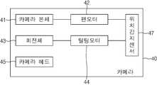
도 4는 도 1의 카메라의 사시도,4 is a perspective view of the camera of FIG. 1, FIG.
도 5는 도 4의 카메라의 블럭구성도,5 is a block diagram of the camera of FIG. 4;
도 6은 도 1의 이벤트감지그룹의 블록구성도,6 is a block diagram of an event detection group of FIG. 1;
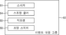
도 7은 도 1의 이벤트대응그룹의 블록구성도,7 is a block diagram of an event response group of FIG. 1;
도 8은 도 1의 클라이언트컴퓨터에 표시되는 클라이언트용 디스플레이 창의 화면,8 is a screen of a display window for a client displayed on the client computer of FIG.
도 9는 본 발명에 따른 무인 감시 시스템의 카메라 작동 제어과정을 도시한 흐름도,9 is a flowchart illustrating a camera operation control process of the unmanned surveillance system according to the present invention;
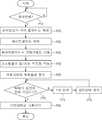
도 10은 본 발명에 따른 무인 감시 시스템의 이벤트 발생시 대응과정을 도시한 흐름도,10 is a flowchart illustrating a response process when an event occurs in the unmanned surveillance system according to the present invention;
도 11은 본 발명의 다른 실시예에 따라 DVR을 설치한 무인 감시 시스템의 개략적 구성도,11 is a schematic configuration diagram of an unmanned surveillance system equipped with a DVR according to another embodiment of the present invention;
도 12는 도 11의 DVR에 표시되는 DVR용 디스플레이 창의 화면이다.12 is a screen of a display window for a DVR displayed on the DVR of FIG.
* 도면의 주요 부분에 대한 부호의 설명* Explanation of symbols for the main parts of the drawings
10 : 서버컴퓨터 11 : 데이터베이스10: server computer 11: database
13 : 클라이언트컴퓨터 15 : 제어그룹13: Client Computer 15: Control Group
16 : 통신모듈 17 : 모션 트랙킹부16: communication module 17: motion tracking unit
18 : 콘트롤러 19 : 직선보간부18: controller 19: linear interpolation unit
20 : 서버용 디스플레이 창 21 : 감지모드버튼20: Display window for server 21: Detect mode button
22 : 순찰모드버튼 23 : 녹화모드버튼22: patrol mode button 23: recording mode button
24 : 센서모드버튼 25 : 상황바아24: sensor mode button 25: status bar
27 : 줌버튼 29 : 카메라선택용 펼침메뉴27: Zoom Button 29: Camera Selection Open Menu
31 : 서버온버튼 32 : 감시설정버튼31: Server On Button 32: Monitoring Setting Button
33 : 모션버튼 35 : 셋업버튼33: Motion button 35: Setup button
40 : 카메라 41 : 카메라본체40: camera 41: camera body
42 : 팬모터 43 : 회전체42: fan motor 43: rotating body
44 : 틸팅모터 45 : 카메라헤드44: tilting motor 45: camera head
47 : 위치감지부 50 : 이벤트감지그룹47: location detection unit 50: event detection group
51 : 인체감지센서 52 : 화재감지센서51: human body detection sensor 52: fire detection sensor
53 : 도어개폐감지센서 54 : 창문개폐감지센서53: door opening and closing detection sensor 54: window opening and closing detection sensor
55 : 조명감지센서 60 : 이벤트대응그룹55: light detection sensor 60: event response group
61 : 스피커 62 : 도어잠금장치61: speaker 62: door lock
63 : 창문잠금장치 64 : 스프링클러63: window lock 64: sprinkler
65 : 덕트팬 66 : 조명스위치65: duct fan 66: light switch
70 : I/O 모듈70: I / O module
본 발명은, 무인 감시 시스템 및 그 제어방법에 관한 것으로서, 보다 상세하게는, 촬영이 필요한 다수의 감시지점을 미리 설정하고, 카메라의 절대위치를 파악하여 카메라가 감시지점을 정확히 향하고 있는지를 판단한 다음, 판단결과에 따라 카메라의 작동을 제어하여 카메라가 정확하게 감시지점을 촬영할 수 있도록 함으로써, 감시지점을 정확하고 효율적으로 감시할 수 있도록 하는 무인 감시 시스템 및 그 제어방법에 관한 것이다.The present invention relates to an unmanned surveillance system and a control method thereof, and more particularly, to set a plurality of surveillance points to be photographed in advance, determine the absolute position of the camera, and then determine whether the camera is directed to the surveillance point. In addition, the present invention relates to an unmanned surveillance system and a control method of controlling an operation of a camera according to a determination result so that the camera can accurately capture a monitoring point, thereby accurately and efficiently monitoring the monitoring point.
예전에는 사회적, 국제적으로 많은 행사를 유치하는 건물이나 시설, 중요 물건을 보관하는 은행과 같은 시설, 테러의 우려가 있는 국방상 중요한 건물이나 시설 등에 무인 감시 시스템에 설치되었으나, 최근에는 아파트, 공항, 일반 매장, 학교/학원, 소규모 사업장, 병원, 주차장 등 다양한 곳에서 도난이나 테러의 우려가 있는 장소에 보안이나 방범의 목적으로 설치되고 있다.In the past, it has been installed in unmanned surveillance systems in buildings and facilities that attract many social and international events, facilities such as banks that store important objects, and important buildings and facilities that are important for terrorism. It is installed for security and crime prevention in places where there is a risk of theft or terrorism in various places such as stores, schools / schools, small businesses, hospitals and parking lots.
이러한 무인 감시 시스템에서 채용되는 가장 일반적이고 보편적인 시스템은, CCTV 카메라를 이용한 것이나, 최근에는 CCTV카메라를 대신하여 USB카메라, 웹카메라 등도 사용되고 있다.The most common and common systems employed in such unmanned surveillance systems are CCTV cameras, but recently, USB cameras and web cameras have been used in place of CCTV cameras.
일반적으로 무인 감시 시스템에서 사용되는 카메라는, 본 발명의 도 3 및 도 4를 참조하여 살펴보면, 벽면에 고정되는 카메라본체와, 벽면에 수직하는 회전축을 중심으로 회전하는 회전체와, 회전체에 설치되어 벽면에 평행한 회전축을 중심으로 일정 범위 각도내에서 회동하는 카메라헤드를 갖는다.In general, the camera used in the unmanned surveillance system, referring to Figures 3 and 4 of the present invention, the camera body fixed to the wall, the rotating body rotating around the axis of rotation perpendicular to the wall, and installed in the rotating body And a camera head that rotates within a range of angles about an axis of rotation parallel to the wall.
카메라본체와 회전체 내에는 각각 회전체와 카메라헤드를 구동하기 위한 팬모터와 틸팅모터, 및 팬모터와 틸팅모터의 회전에 따라 카메라헤드의 위치를 감지하는 위치감지부가 설치되어 있다.The camera body and the rotating body are provided with a pan motor and a tilting motor for driving the rotating body and the camera head, and a position sensing unit for detecting the position of the camera head according to the rotation of the pan motor and the tilting motor.
이러한 무인감시시스템의 카메라는 통상적으로 감지구역의 모서리 공간에 설치되기 때문에 팬모터와 틸팅모터는 일정 각도 범위내에서 회동가능하게 제작되며, 감시구역이 넓은 경우에는 복수의 카메라를 설치하여 감시구역을 촬영하게 된다.Since the camera of such unmanned surveillance system is usually installed in the corner space of the detection zone, the fan motor and the tilting motor can be rotated within a certain angle range, and if the surveillance zone is large, a plurality of cameras can be installed to monitor the surveillance zone. I will shoot.
감시구역의 촬영시, 카메라헤드는 일정한 방향성을 가지고 회동되어 감시구역을 연속적으로 촬영하게 되며, 위치감지부는 팬모터와 틸팅모터의 회전정도에 따라 카메라헤드의 위치를 판단하게 된다. 즉, 위치감지부는 팬모터와 틸팅모터가 몇 도를 회전하였는지, 내지는 동작시작후 시간이 얼마나 지났는지에 따라, 카메라헤드가 임의의 위치에 도달하였다고 추정한다. 따라서 종래에는 위치감지부를 통해 카메라헤드의 상대적 위치를 판단할 수 있을 뿐이며, 카메라헤드가 향하고 있는 실제 위치인 절대위치는 파악할 수가 없었다.When shooting the surveillance zone, the camera head is rotated with a certain direction to shoot the surveillance zone continuously, the position detection unit determines the position of the camera head according to the degree of rotation of the pan motor and the tilting motor. That is, the position detecting unit estimates that the camera head has reached an arbitrary position depending on how many degrees the fan motor and the tilting motor have rotated, or how much time has passed since the start of operation. Therefore, in the related art, only the relative position of the camera head can be determined through the position detecting unit, and the absolute position, which is the actual position of the camera head, cannot be determined.
한편, 종래의 카메라는 지정된 감시구역 내의 모든 영역에서 동일한 속도와 시간으로 회동하면서 감시구역을 촬영하고 있다. 그러나 일반적으로 카메라가 설치된 감시구역내에서도 특히 관심을 두고 감시해야 하는 감시지점, 예를 들면, 금 고, 서류함, 도어 등 다수의 감시지점이 존재하며, 이러한 감시지점을 감시하기 위해 무인 감시 시스템을 설치했을 확률이 크다. 그러나 종래의 카메라에서처럼 감시구역을 연속적으로 촬영할 경우에는 감시구역내의 모든 감시지점에서 카메라의 촬영시간이 동일하므로, 특정위치에서 일정 시간동안 머물면서 집중적인 녹화를 하거나 특정위치는 감시횟수를 늘기거나 하는 한 단계 진보된 보안 및 방범을 수행할 수 없다. 따라서 감시지점의 보안 및 방범이 상대적으로 소홀해진다는 문제점이 있다.On the other hand, the conventional camera photographs the surveillance zone while rotating at the same speed and time in all the regions within the designated surveillance zone. In general, however, there are a number of monitoring spots that must be monitored with particular interest in the surveillance zones where cameras are installed, such as safes, filing cabinets and doors. It is likely that you would. However, when shooting surveillance zones continuously, as in conventional cameras, the camera's shooting time is the same at all surveillance points within the surveillance zone. You can't perform one level of advanced security and security. Therefore, there is a problem that the security and security of the monitoring point is relatively neglected.
한편, 종래 무인 감시 시스템은 감시구역을 CCTV 카메라로 촬영하여 화면을 녹화하여 두거나, 상황실 등에서 근무자가 이를 원격 감시하는 방법이 대부분이다. 즉, 종래의 무인 감시 시스템은, 근무자의 육안을 통해서만 침입자의 발생여부를 감지할 수 있으므로, 근무자가 자리를 이탈하거나, 방심하는 순간에 침입이 발생하면 즉각적인 조처가 불가능하다. 이에 따라, 대부분의 카메라 녹화 시스템은 사후 원인규명 차원에서 다루어지는 경우가 많다. 즉, 사고가 발생한 이후에 침입자를 발본색출하기 위해 녹화된 화상을 재생하게 되는 경우가 대부분이다.On the other hand, in the conventional unmanned surveillance system, the surveillance zone is recorded with a CCTV camera to record the screen, or the worker in the situation room, such as most of the remote monitoring method. In other words, the conventional unmanned surveillance system can detect whether the intruder is generated only through the naked eye of the worker, so if the worker leaves the room or the intrusion occurs at the moment of being alert, no immediate action is possible. Accordingly, most camera recording systems are often dealt with in terms of post cause identification. That is, in most cases, the recorded image is reproduced in order to detect and extract an intruder after an accident occurs.
이렇듯 종래 보안 및 방범 기술로 채용되는 가장 일반적이고 보편적인 카메라 녹화 시스템은 침입자에게 침입에 대한 곤란성을 제공하기는 하지만 근본적인 침입 방지를 수행하지 못하며, 침입자가 발생하여도 이를 추적하지 못할 뿐만 아니라, 침입에 따른 위험행동이 이루어지더라도 즉각적인 대처를 수행하지 못하는 단점이 있다.As such, the most common and common camera recording systems employed by conventional security and security technologies provide intruders with difficulty in intrusion, but do not perform fundamental intrusion prevention, and do not track intrusions as they occur. Even if the risk action is taken, there is a drawback that it is not possible to take immediate action.
한편, 근래에는 원격지에서도 감시구역을 실시간으로 감시할 수 있도록, 감 시구역에 설치한 카메라에서 촬영된 영상을 네트워크를 통해 원격지로 전송하여 영상을 감시할 수 있도록 하는 시스템이 사용되고 있다. 그러나 이러한 방법도 감시구역에서 비상상황이 발생하더라도 단순히 감시구역에 관한 영상정보만을 고객 및 중앙관제센터로 전송해 주는 기능만을 수행하므로, 관리자가 비상상황에 대한 신속한 대응을 할 수 없다는 문제점이 여전히 존재한다. 또한, 비상상황이 발생된 감시구역이 영상정보를 제대로 확보할 수 없을 만큼 어두운 경우에는 조명을 계속 켜 두거나 또는 어두운 상태의 영상정보를 확보해야만 하므로, 에너지 낭비 또는 정확한 상황분석을 어렵게 하는 문제점도 있었다.On the other hand, in recent years, in order to monitor the monitoring area in real time even in the remote area, a system for monitoring the image by transmitting the image taken by the camera installed in the monitoring area to the remote place through the network has been used. However, even in the case of an emergency in the monitoring area, this method only transmits the video information of the monitoring area to the customer and the central control center. Therefore, there is still a problem that the administrator cannot respond to the emergency quickly. do. In addition, when the surveillance zone where the emergency situation is dark enough to not properly secure the image information, it is necessary to keep the lighting on or secure the image information in the dark state, which also makes it difficult to waste energy or to accurately analyze the situation. .
따라서 본 발명의 목적은, 특별한 감시가 요구되는 다수의 감시지점을 미리 설정하고, 카메라의 절대위치를 파악하여 카메라의 구동을 제어함으로써, 감시지점의 정확한 촬영이 가능하도록 하는 무인 감시 시스템 및 그 제어방법을 제공하는 것이다.Accordingly, an object of the present invention is to set up a plurality of monitoring points that require special monitoring in advance, and to control the driving of the camera by grasping the absolute position of the camera, thereby enabling an unattended monitoring system and control thereof. To provide a way.
본 발명의 다른 목적은, 감시구역내에서 발생하는 이벤트를 실시간으로 감지하고 이에 대응함으로써, 원격지에서 이벤트를 보다 효과적이고 신속하게 해소할 수 있도록 하는 무인 감시 시스템 및 그 제어방법을 제공하는 것이다.It is another object of the present invention to provide an unmanned monitoring system and a control method thereof, by detecting an event occurring in a monitoring area in real time and responding to the event in real time to more effectively and quickly resolve the event at a remote location.
상기 목적은, 본 발명에 따라, 감지구역내의 벽면에 고정되는 카메라본체와, 상기 카메라본체에 회전가능하게 결합되어 상기 벽면에 수직하는 회전축을 중심으로 회전하는 회전체와, 상기 회전체의 일측에 설치되어 상기 벽면과 수평을 이루는 회전축을 중심으로 회전하는 카메라헤드를 갖는 카메라와; 상기 카메라에서 촬영된 영상을 제공받는 서버컴퓨터를 포함하는 무인 감시 시스템에 있어서, 상기 카메라는, 상기 카메라본체내에 설치되며 상기 회전체를 구동시키기 위한 팬모터와, 상기 회전체내에 설치되며 상기 카메라를 구동시키기 위한 틸팅모터와, 상기 팬모터와 틸팅모터의 절대위치를 감지하기 위한 위치감지부를 더 포함하며; 상기 서버컴퓨터는, 감시가 요구되는 복수의 감시지점에 대한 절대위치 정보가 저장되어 있는 메모리와, 상기 위치감지부로부터의 감지결과에 따라 상기 카메라헤드가 상기 감시지점에 도달하도록 상기 팬모터와 틸팅모터를 제어하는 콘트롤러를 포함하는 것을 특징으로 하는 무인 감시 시스템에 의해 달성된다.The object is, according to the present invention, a camera body fixed to the wall surface in the detection zone, a rotating body rotatably coupled to the camera body to rotate about a rotation axis perpendicular to the wall surface, and on one side of the rotating body A camera having a camera head installed to rotate about a rotation axis parallel to the wall surface; In the unmanned surveillance system including a server computer for receiving the image taken by the camera, the camera is installed in the camera body and a fan motor for driving the rotating body, and installed in the rotating body and the camera A tilting motor for driving, and a position sensing unit for sensing an absolute position of the fan motor and the tilting motor; The server computer may include a memory in which absolute position information of a plurality of monitoring points requiring monitoring is stored, and the fan motor and tilting so that the camera head reaches the monitoring points according to a detection result from the position detecting unit. It is achieved by an unmanned monitoring system comprising a controller for controlling the motor.
여기서, 상기 위치감지부는, 상기 팬모터와 틸팅모터의 절대위치에 대한 전압을 감지하는 포텐시오미터인 것이 바람직하다.Here, the position detecting unit, it is preferable that the potentiometer for sensing the voltage for the absolute position of the fan motor and the tilting motor.
상기 감시지점에 화재, 침입 등의 이벤트가 발생되었음을 감지하는 이벤트감지그룹과; 상기 감시지점의 스프링클러, 조명, 스피커, 도어, 창문 등 상기 이벤트를 해소할 수 있는 이벤트대응그룹을 포함함으로써, 원격지에서 이벤트를 해소할 수 있다.An event detection group detecting that an event such as a fire or an intrusion has occurred at the monitoring point; By including an event response group that can resolve the event, such as sprinklers, lights, speakers, doors, windows of the monitoring point, it is possible to resolve the event at a remote location.
상기 이벤트감지그룹은, 상기 감시구역에 침입한 침입자를 감지하기 위한 인체감지센서와; 열 또는 가스의 감지를 이용하여 화재를 감지하기 위한 화재감지센서와; 상기 감시구역의 도어 또는 창문의 개폐여부를 감지하기 위한 도어개폐감지센서 또는 창문개폐감지센서와; 상기 카메라가 촬영하는 감시지점의 조명 온오프 여부를 감지하기 위한 조명감지센서 중 적어도 하나를 사용할 수 있다.The event detection group includes a human body sensor for detecting an intruder entering the surveillance zone; A fire detection sensor for detecting a fire by using heat or gas detection; A door opening / closing sensor or a window opening / closing sensor for detecting whether the door or window of the monitoring zone is opened or closed; At least one of the light detection sensors for detecting whether the illumination point of the monitoring point photographed by the camera may be used.
상기 콘트롤러는, 클라이언트의 유무선 단말기와 통신가능한 통신모듈을 더 포함하며; 상기 콘트롤러는 이벤트의 발생시 상기 통신모듈을 통해 상기 클라이언트에게 연락하는 것이 바람직하다.The controller further comprises a communication module capable of communicating with the wired and wireless terminal of the client; Preferably, the controller contacts the client through the communication module when an event occurs.
한편, 상기 목적은, 본 발명의 다른 분야에 따르면, 감시구역내의 벽면에 고정되는 카메라본체와, 상기 카메라본체에 회전가능하게 결합되어 상기 벽면에 수직하는 회전축을 중심으로 회전하는 회전체와, 상기 회전체의 일측에 설치되어 상기 벽면과 수평을 이루는 회전축을 중심으로 회전하는 카메라헤드를 갖는 카메라와; 상기 카메라에서 촬영된 영상을 제공받는 서버컴퓨터를 포함하는 무인 감시 시스템의 제어방법에 있어서, 상기 감시구역내에서 특별한 감시를 요하는 복수의 감시지점을 지정하여 각 감시지점에 대한 절대위치 정보를 저장하는 감시지점 지정단계와; 상기 카메라헤드의 구동시, 상기 카메라헤드가 촬영하는 영역의 절대위치를 감지하는 절대위치 감지단계와; 상기 카메라헤드의 절대위치와, 상기 미리 지정된 감시지점에 대한 절대위치를 비교하여 상기 카메라헤드가 상기 감시지점 중 어느 것을 촬영하고 있는지 여부를 판단하는 위치판단 단계와; 상기 카메라헤드의 절대위치와, 상기 미리 지정된 감시지점에 대한 절대위치가 일정 오차범위 이상일 경우, 상기 카메라헤드를 구동하기 위한 모터를 작동시켜 상기 카메라헤드를 상기 감시지점으로 이동시키는 위치보정단계를 포함하는 것을 특징으로 하는 무인 감시 시스템의 제어방법에 의해서도 달성될 수 있다.On the other hand, the object is, according to another field of the present invention, a camera body fixed to the wall surface in the surveillance zone, and a rotatable body rotatably coupled to the camera body to rotate around the axis of rotation perpendicular to the wall, and A camera installed at one side of the rotating body and having a camera head rotating about a rotation axis parallel to the wall surface; A control method of an unmanned surveillance system including a server computer receiving an image captured by the camera, the method comprising: designating a plurality of surveillance points requiring special surveillance in the surveillance zone to store absolute position information of each surveillance point. A monitoring point designating step; An absolute position sensing step of sensing an absolute position of an area photographed by the camera head when the camera head is driven; A position determining step of determining whether the camera head is photographing the monitoring point by comparing an absolute position of the camera head with an absolute position with respect to the predetermined monitoring point; And a position correction step of moving the camera head to the monitoring point by operating a motor for driving the camera head when the absolute position of the camera head and the absolute position with respect to the predetermined monitoring point are above a predetermined error range. It can also be achieved by a control method of an unmanned surveillance system characterized in that.
이하에서는 첨부도면을 참조하여 본 발명에 대해 상세히 설명한다.Hereinafter, the present invention will be described in detail with reference to the accompanying drawings.
본 무인 감시 시스템은, 감시구역에서 특별한 감시가 요구되는 다수의 감시 지점을 설정하고, 감시지점에 정확히 카메라헤드가 배치되도록 카메라의 모터를 제어함으로써, 감시지점에 대해 정확한 촬영이 이루어져 감시지점의 보안 및 방범 효과를 향상시킬 수 있도록 한다. 또한, 외부로부터의 침입, 화재 등의 이벤트가 발생하였을 경우, 감시구역내에 설치된 경보장치, 소화기장치 등을 원격조정으로 작동시킬 수 있도록 함으로써, 원격지에서 침입, 화재 등의 이벤트를 해소할 수 있도록 한다.This unmanned surveillance system sets up a number of surveillance points that require special surveillance in the surveillance area, and controls the camera's motor so that the camera head is placed exactly at the surveillance point, so that accurate monitoring of the surveillance point is achieved. And to improve the security effect. In addition, when an event such as an invasion or fire from the outside occurs, an alarm device, a fire extinguisher device, etc. installed in the monitoring area can be operated by remote control, so that an event such as an intrusion or fire can be eliminated remotely. .
본 무인 감시 시스템은, 도 1에 도시된 바와 같이, 감시구역에 설치되어 감시구역을 촬영하는 복수의 카메라(40)와, 각 카메라(40)에 연결되어 각 카메라(40)로부터 촬영된 영상을 저장 및 표시하는 서버컴퓨터(10)와, 서버컴퓨터(10)와 통신가능하게 원격지에 설치되어 각 카메라(40)에서 촬영중이거나 촬영된 영상을 표시할 수 있는 클라이언트컴퓨터(13)를 갖는다. 여기서, 카메라(40)에는, 감시구역 내에 설치되며 감시구역내의 침입, 화재 등의 이벤트를 감지하는 이벤트감지그룹(50)과, 감시구역 내에 설치되어 이벤트를 해소하는 이벤트대응그룹(60)이 연결되어 있으며, 이벤트감지그룹(50) 및 이벤트대응그룹(60)과 카메라(40) 사이에는 I/O모듈(70)이 설치되어 이벤트감지그룹(50)으로부터 수신된 정보를 카메라(40)로 제공하고, 카메라(40)를 통해 전달된 명령을 이벤트대응그룹(60)으로 제공한다.As shown in FIG. 1, the unmanned surveillance system includes a plurality of
여기서, 서버컴퓨터(10)와 클라이언트컴퓨터(13)에는 각각 서버용 프로그램과, 클라이언트용 프로그램이 설치되며, 서버용 프로그램은 네트워크를 통해 접속된 원격지의 클라이언트컴퓨터(13)에서 카메라를 제어하고 모니터링 할 수 있도록 서비스를 제공하고, 클라이언트용 프로그램은 클라이언트컴퓨터(13)가 원격지에서 서버컴퓨터(10)에 접속할 수 있도록 한다.Here, a server program and a client program are installed in the
서버컴퓨터(10)에 서버용 프로그램을 설치하면, 도 2에 도시된 바와 같은, 서버용 디스플레이 창이 디스플레이된다. 서버용 디스플레이 창에는, 그 중앙영역에 카메라로 촬영된 화면이 디스플레이되는 디스플레이부(30)가 형성되어 있고, 디스플레이부(30)의 상부와 하부에는 각각 다양한 기능의 선택을 위한 버튼들이 마련되어 있다.When the server program is installed in the
먼저, 창의 상부에는 감지모드버튼(21), 순찰모드버튼(22), 녹화모드버튼(23), 센서모드버튼(24) 등의 기능버튼이 형성되어 있다. 감지모드버튼(21)은 감시지점의 움직임을 감지하여 클라이언트에게 소리, 녹음, 녹화, 알람, 메일 등을 이용하여 알려주는 기능을 선택하는 버튼이며, 순찰모드버튼(22)은 클라이언트가 미리 지정한 순서에 따라 감시지점을 순차적으로 촬영하도록 카메라를 작동시키는 버튼이고, 녹화모드버튼(23)은 현재 영상을 녹화하고자 할 때 선택하는 버튼이고, 마지막으로 센서모드버튼(24)은 이벤트감지그룹에 의해 감지된 결과에 따라 미리 설정된 이벤트대응그룹(60)이 동작하도록 선택하는 버튼이다. 여기서, 감시지점은 금고, 쇼윈도, 도어, 창문 등과 같이 특별한 감시를 요하는 영역을 지칭하며, 이러한 감시지점은 클라이언트에 의해 미리 지정될 수 있으며, 클라이언트의 지정에 따라, 감시지점에 대한 정보, 예를 들면, 감시지점의 명칭, 촬영시 조명의 턴온여부, 감시지점의 절대위치 등이 후술할 데이터베이스에 저장된다.First, function buttons such as a
이러한 기능버튼의 하부에는 상황바아(25)가 형성되어 있으며, 상황바아(25) 에는 감지모드, 순찰모드, 녹화모드, 센서모드의 작동시 각각 색이 진해지거나 불이 켜지는 감지모드아이콘, 순찰모드아이콘, 녹화모드아이콘, 센서모드아이콘과 함께, 클라이언트컴퓨터(13)의 서버컴퓨터(10) 접속여부를 표시하는 접속아이콘과, 감지모드 설정시 움직임이 감지됨을 표시하는 경고아이콘이 각각 형성되어 있다.A
디스플레이부(30)의 하부에는, 서버용 프로그램을 동작시켜 디스플레이부에 촬영중인 영상을 표시하고 원격지의 클라이언트컴퓨터(13)에 촬영된 영상을 전송하기 위한 서버온버튼(31)과, 감시위치, 순찰패턴, 이벤트감지그룹의 작동을 설정하기 위한 감시설정버튼(32)과, 카메라의 기능과 이벤트대응그룹의 작동 여부를 설정하기 위한 모션버튼(33)과, 감시지점, 화질, 감지감도 등을 설정하기 위한 셋업버튼(35)과, 이미지를 확대 및 축소하기 위한 줌버튼(2)과 함께, 카메라가 여러 대 설치된 경우 카메라를 선택하기 위한 카메라선택용 펼침메뉴(29)가 형성되어 있다.In the lower part of the
이러한 서버용 프로그램이 설치된 서버컴퓨터(10)는, 카메라(40)를 통해 I/O 모듈(70)과 연결되어 카메라(40)의 작동상태와 이벤트감지그룹(50)으로부터 감지된 이벤트에 대한 정보를 제공받으며, 제공받은 정보에 따라 카메라(40) 및 이벤트대응그룹(60)의 작동을 제어하게 된다. 이를 위해, 서버컴퓨터(10)에는, 컴퓨터내에 각종 정보를 저장하기 위한 데이터베이스(11)와, 카메라(40)와 이벤트감지그룹(50)으로부터 제공된 정보에 대응하여 적절한 제어를 수행하기 위한 제어그룹(15)이 마련되어 있다.The
제어그룹(15)은, 두 위치를 지나는 함수를 직선의 방정식으로 산출하여 카메라(40)가 두 위치를 연결하는 직선을 따라 이동할 수 있도록 하는 직선보간부(19) 와, 감시구역내에서 움직임이 감지되면 움직임에 따라 카메라헤드(45)를 회동시키기 위한 모션 트랙킹부(17)와, 보안 및 방범을 의뢰한 클라이언트의 유무선 단말기와 연결하기 위한 통신모듈(16)과, 카메라(40)로부터 제공된 영상정보와 이벤트감지그룹(50)로부터의 이벤트감지에 따라 통신모듈(16)을 통해 클라이언트에게 정보를 제공하고 카메라(40)와 이벤트감지그룹(50)으로부터 제공된 정보에 대응하여 적절한 제어를 수행하기 위한 콘트롤러(18)를 포함한다.The
여기서, 통신모듈(16)은, 공중 회선이나 ISDN(Integrated Service Digital Network) 회선을 경유하여 다이얼 업 접속을 행하는 경우에는, PPP(point-to-point protocol) 프로토콜을 지원하고, PHS(Personal Handyphone System)의 PIAFS(PHS Internet Access Forum Standard)를 사용하는 경우에는, PIAFS I/F와 그 드라이버를 지원하며, 구내 LAN(Local Area Network)에 연결하는 경우에는, Ethernet(이더넷) I/F와 그 드라이버를 지원한다. 그 밖에 상술한 TCP/IP(Transmission Control Protocol/Internet Protocol), UDP(User Datagram Protocol), IP, FTP(File Transfer Protocol)나 RS-162C I/F를 지원할 수 있다.Here, the
한편, 감시구역의 촬영을 위한 카메라(40)는 CCTV 카메라, USB카메라, 네트워크에 연결된 웹카메라 등 다양한 종류의 카메라(40)로 구성될 수 있다. 일반적인 CCTV 카메라 또는 USB카메라는 선의 길이에 제한이 있으므로 동일건물 또는 동일지역 내에 설치되며, 웹카메라는 인터넷을 통해 동영상을 전달하게 되므로 설치거리의 제한이 없다. 카메라(40)는 CCD 또는 CMOS 타입으로 형성될 수 있으며, 카메라(40)에서 촬상된 영상은 카메라(40)의 타입에 따라 USB 방식, NTSC 방식, PAL 방식 중 하나의 방식으로 저장 및 전송된다.On the other hand, the
이러한 카메라(40)는, 도 4 및 도 5에 도시된 바와 같이, 벽면에 고정되는 카메라본체(41)와, 벽면에 수직하는 회전축을 중심으로 회전가능하도록 카메라본체(41)에 결합되는 회전체(43)와, 회전체(43)에 설치되어 벽면에 평행한 회전축을 중심으로 일정 범위 각도내에서 회동하는 카메라헤드(45)를 포함한다. 그리고 카메라본체(41)내에는 회전체(43)를 구동시키기 위한 팬모터(42)가 설치되어 있고, 회전체(43) 내에는 카메라헤드(45)를 구동시키기 위한 틸팅모터(44)가 설치되어 있으며, 이와 함께, 팬모터(42)와 틸팅모터(44)의 절대위치를 감지하기 위한 위치감지부(47)가 장착되어 있다.4 and 5, the
카메라(40)는 감지구역내에 하나 또는 복수개가 설치되며, 팬모터(42)는 보통 300도에서 320도의 회전각 범위내에서 회전가능하도록 설계되고, 틸팅모터(44)는 70도에서 120도의 범위내에서 회동가능하도록 설계된다.One or
여기서, 팬모터(42)와 틸팅모터(44)는 다양한 형태의 DC모터를 사용하며, 팬모터(42)와 틸팅모터(44)에는 모터의 속도를 가감하기 위한 가감속기가 설치되어 상황에 따라 팬모터(42)와 틸팅모터(44)의 가속 또는 감속함으로써 속도를 조절할 수 있다. 또한, 팬모터(42)와 틸팅모터(44)로 스텝모터를 사용하거나 인버터 등을 적용함으로써, 속도를 다단계 또는 연속적으로 조절할 수도 있다.Here, the
한편, 팬모터(42)와 틸팅모터(44)의 절대위치인 각도를 감지하는 위치감지부(47)는, 가변저항의 일종으로 아날로그 방식의 절대위치 측정 센서인 포텐시오미터(47)를 사용하며, 포텐시오미터(47)는 팬모터(42)와 틸팅모터(44)의 각 도를 전압의 크기로서 기억한다. 이러한 포텐시오미터(47)로부터 감지된 전압은 팬모터(42)와 틸팅모터(44)의 각도로 변환되어 콘트롤러(18)로 제공되며, 콘트롤러(18)는 메모리(22)에 저장된 감시지점에서의 팬모터(42) 및 틸팅모터(44)의 각도와, 현재 카메라(40)가 정지된 위치에서의 팬모터(42) 및 틸팅모터(44)의 각도를 비교함으로써, 카메라헤드(45)가 어떤 감시지점을 향하고 있는지를 파악할 수 있을 뿐만 아니라, 팬모터(42)와 틸팅모터(44)의 각도로 카메라헤드(45)가 얼마나 정확하게 감시지점을 향하고 있는지 알 수 있다.On the other hand, the
이러한 카메라헤드(45)는, 클라이언트가 순찰모드버튼을 이용하여 설정한 감시지점의 순찰순서에 따라 감시지점을 순차적으로 감시하게 되며, 이 때, 클라이언트의 선택에 따라, 각 감시지점에서 소정 시간 동안 머물면서 촬영을 할 수도 있고, 특정 감시지점에 대해서는 타 영역에 비해 감시 횟수를 증가시켜 여러 번 촬영할 수도 있다. 감시지점을 제외한 감시구역에서는 종래와 마찬가지로 연속적으로 카메라(40)를 이동시키면서 촬영할 수도 있다.The
한편, 감지구역내에 설치된 이벤트감지그룹(50)은, 도 6에 도시된 바와 같이, 침입 여부를 판단하는 인체감지센서(51)와, 화재를 감지하는 화재감지센서(52)와, 도어 및 창문의 개폐를 감지하는 도어개폐감지센서(53) 및 창문개폐감지센서(54)와, 조명의 온오프를 감지하는 조명감지센서(55) 등 감지구역내에서 발생할 수 있는 다양한 이벤트를 감지하는 다양한 형태의 센서를 포함한다.On the other hand, the
인체감지센서(51)는, 인체의 체온에 의해 형성되는 적외선을 감지하기 위한 적외선센서(51a)로 마련할 수도 있고, 출입이 허가된 출입인에게 배부된 출입증에 서 발생하는 RF주파수신호를 감지하는 RF감지센서(51b)로 마련할 수도 있다. 적외선센서(51a)는, 주로 감시구역의 출입이 통제되는 야간이나 특정한 통제시간에 사용할 수 있으며, 출입여부의 통지가 없는 상태에서 인체가 감지될 경우에는 외부인의 침입이 발생한 것으로 판단할 수 있다. 이에 반해, RF감지센서(51b)를 사용하는 경우는 주간과 야간에 무관하게 사용될 수 있으며, 인체로부터 RF주파수신호가 발생되지 않는 경우, 즉 출입증이 없는 자는 칩입자로 판단할 수 있다. 이러한 적외선센서(51a)와 RF감지센서(51b) 이외에 침입을 감지할 수 있는 다양한 형태의 센서를 사용할 수 있음은 물론이다.The human
한편, 화재감지센서(52)는, 화재 발생시 열을 감지하는 열감지센서(52a)와, 화재로 인해 발생하는 가스를 감지하는 가스감지센서(52b) 중 어느 하나로 마련될 수 있다. 또한, 도어개폐감지센서(53) 및 창문개폐감지센서(54)는 도어와 도어프레임, 창문과 창문프레임에 각각 부착되어 상호 접촉 및 이격을 감지하는 마그네틱 센서로 형성되어 도어와 창문의 개폐여부를 판단한다.On the other hand, the
이러한 이벤트감지그룹(50)에 의해 감지된 이벤트를 해소하기 위해 서버컴퓨터(10)로부터의 명령에 의해 작동되는 이벤트대응그룹(60)은, 도 7에 도시된 바와 같이, 서버컴퓨터(10)를 통해 실시간으로 제공된 경고음 또는 경고메시지 등의 출력을 위한 스피커(61)와, 방화수의 분사를 위한 스프링클러(64)와, 연기의 배출을 위한 덕트팬(65), 및 조명의 턴온을 위한 조명스위치(66) 등을 포함한다. 이러한 이벤트대응그룹(60)은, 각각의 이벤트의 발생시 단독으로 혹은 다른 장치와 함께 작동하여 이벤트를 해소하게 된다.The
일예로, 인체감지센서(51)를 통해 인체가 감지되고, 도어개폐감지센서(53)를 통해 도어의 잠금해제가 감지되면, 콘트롤러(18)에서는 도어를 통해 침입자가 발생하였다고 판단한다. 이에, 콘트롤러(18)는 스피커(61)를 통해 경고음 또는 경고메시지를 출력하도록 제어신호를 발생시키게 된다. 다른 예로, 감시구역이 원래 어둡거나 야간인 경우, 콘트롤러(18)는 포텐시오미터(47)에 의해 감지된 카메라(40)의 절대위치인 감시지점에 대한 정보와, 메모리(22)로부터 감시지점에 대한 정보를 인출하여 해당 감시지점에서 조명을 턴온시켜야 하는지 판단한다. 판단 결과, 해당 감시지점에서 조명의 턴온이 요구되는 경우, 콘트롤러(18)는 조명스위치(66)를 턴온시켜 조명이 켜지도록 함으로써 카메라(40)를 통한 촬영이 용이하도록 한다.For example, when the human body is detected through the
이러한 서버컴퓨터(10)에 접속가능한 클라이언트컴퓨터(13)는, 유무선 단말기, PDA, 휴대폰 등 네트워크를 통해 접속이 가능한 대부분의 통신수단을 지칭한다. 클라이언트컴퓨터(13)에는 서버컴퓨터(10)와는 별도로 클라이언트용 프로그램이 설치되며, 클라이언트용 프로그램이 설치되면, 도 8에 도시된 바와 같은 프로그램 창이 디스플레이된다. 클라이언트용 프로그램의 창은, 서버용 프로그램의 창에서 제공하고 있는 내용과 거의 동일하나, 서버용 프로그램에서 제공하는 서버온버튼(31) 대신 서버와의 연결을 선택하기 위한 서버연결버튼(34)이 형성되어 있고, 서버용 프로그램에서 제공하고 있는 셋업버튼이 클라이언트용 프로그램에는 존재하지 않는다. 이러한 차이점 중 가장 중요한 것은, 클라이언트용 프로그램 창에는 멀티뷰아이콘(37)이 형성되어 있다는 것이다. 멀티뷰아이콘(37)을 선택할 경우, 클라이언트컴퓨터(13)의 창이 복수개로 분할되어 복수개의 활성창(39)을 형성하며, 이 때, 클라이언트컴퓨터(13)는 여러 대의 서버컴퓨터(10)에 연결되어 각 서버컴퓨터(10)로부터 제공된 복수의 영상을 각 활성창(39)에 표시할 수 있다. 한편, 한대의 서버컴퓨터(10)에 여러 대의 카메라가 연결된 경우에도 각 카메라(40)로부터 촬영된 영상이 각 활성창(39)에 표시되도록 설정할 수도 있음은 물론이다.The
이러한 구성에 의한 무인 감시 시스템의 기본적인 작동과정을 도 9를 참조하여 상세히 설명하도록 한다.The basic operation of the unmanned monitoring system by such a configuration will be described in detail with reference to FIG. 9.
전원이 인가되어 무인 감시시스템이 작동되면(S10), 팬모터(42)와 틸팅모터(44)가 작동되어 클라이언트가 미리 설정한 순서에 따라 카메라헤드(45)가 다수의 감시지점을 순차적으로 회동하며 촬영하게 된다(S20,S30). 이 때, 포텐시오미터(47)에 의해 팬모터(42)와 틸팅모터(44)의 절대위치인 각도가 감지되어 콘트롤러(18)로 제공되며(S40), 콘트롤러(18)에서는 포텐시오미터(47)에서 감지된 전압에 따른 각도와 데이터베이스에 저장된 감시지점에서의 팬모터(42)와 틸팅모터(44)의 각도를 비교함으로써, 카메라헤드(45)가 정확하게 감시지점을 촬영하고 있는지 여부를 판단하게 된다(S50). 이 때, 카메라헤드(45)가 정확하게 감시지점을 촬영하고 있지 아니한 경우, 콘트롤러(18)는 팬모터(42)와 틸팅모터(44)를 작동시켜 카메라헤드(45)가 감시지점을 향하도록 제어한 다음(S55), 카메라헤드(45)의 위치가 보정되면 촬영을 하도록 한다.When the power is applied and the unmanned surveillance system is operated (S10), the
카메라헤드(45)가 정확하게 감지지점을 향해 있는 경우에는 바로 감시지점을 촬영하도록 하며(S60), 이렇게 촬영된 영상은 서버컴퓨터(10)에 제공되어 서버컴퓨터(10)의 프로그램 창을 통해 디스플레이된다(S70,S80). 서버컴퓨터(10)에서는 촬 영중 클라이언트가 녹화모드버튼(23)을 선택한 경우 촬영된 영상을 데이터베이스(11)에 저장하며, 이벤트 발생시에도 클라이언트가 이벤트에 대한 영상의 저장을 원한 경우에만 이벤트가 발생한 감시지점의 영상을 데이터베이스(11)에 저장하게 된다. 이렇게 감시구역을 촬영하던 중, 클라이언트컴퓨터(13)가 서버컴퓨터(10)에 연결되면, 촬영된 영상이 서버컴퓨터(10)로부터 클라이언트컴퓨터(13)로 제공된다(S90,S100).When the
한편, 감시구역에 이벤트가 발생한 경우 본 무인 감시 시스템에 의한 대응과정을, 도 10을 참조하여 살펴보면 다음과 같다.On the other hand, when the event occurs in the monitoring area look at the response process by the unmanned monitoring system, referring to Figure 10 as follows.
감시구역내에 설치된 인체감지센서(51), 화재감지센서(52), 도어/창문개폐감지센서(54), 조명감지센서(55)로부터 이벤트가 발생되었음이 감지되면, 감지된 이벤트에 대한 정보가 서버컴퓨터(10)로 제공되고, 콘트롤러(18)는 이벤트에 대응하는 조치를 취하게 된다.When an event has been detected from the
예를 들어, 화재감지센서(52)에 의해 화재의 발생이 감지되면(P10), 감지결과가 서버컴퓨터(10)로 제공되고(P20), 콘트롤러(18)는 화재가 발생한 감시지점을 판단한다(P30). 일반적으로 화재감지센서(52)는 감시구역 곳곳에 다수개가 설치되며, 각 화재감지센서(52)의 화재감지 여부와 열 또는 가스의 정도여부에 따라 화재 발생 감시지점을 파악할 수 있다. 화재 발생 감시지점이 파악되면, 콘트롤러(18)는 해당 감시지점을 촬영할 수 있도록 팬모터(42)와 틸팅모터(44)를 작동시켜 카메라헤드(45)가 해당 감시지점을 향하도록 한다(P40). 이 때, 콘트롤러(18)는 직선보간부(19)를 작동시켜 현재 카메라헤드(45)의 위치와 화재 발생 감시지점의 위치 간을 연결하는 직선의 방정식을 구함으로써, 카메라헤드(45)가 직선보간에 의해 결정된 직선을 따라 화재 발생 감시지점으로 이동할 수 있도록 하며, 이 때, 가감속장치를 작동시켜 카메라헤드(45)의 이동속도를 고속으로 제어할 수 있다. 이렇게 카메라헤드(45)를 이동시킴과 동시에, 콘트롤러(18)에서는 스프링클러(64) 및/또는 덕트팬(65)을 작동시킨다. 이 때, 열감지센서(52a)로부터 열기가 감지된 경우에는 스프링클러(64)를 작동시켜 화재를 진화하고, 가스감지센서(52b)로부터 가스가 감지된 경우에는 덕트팬(65)을 작동시켜 가스를 배출한다. 만약, 열감지센서(52a)와 가스감지센서(52b)로부터 열기와 가스가 모두 감지된 경우에는, 스프링클러(64)와 덕트팬(65)을 모두 작동시킨다(P50). 한편, 콘트롤러(18)는 통신모듈(16)을 통해 해당 감시구역의 클라이언트에게 유무선 단말기로 연락하여 화재가 발생하였음을 통지하게 된다(P60).For example, when the occurrence of a fire is detected by the fire detection sensor 52 (P10), the detection result is provided to the server computer 10 (P20), the
이러한 일차적 대응이 완료된 후, 콘트롤러(18)는 화재감지센서(52)로부터의 감지결과에 따라 화재가 완전히 진화되었는지를 판단하고(P70), 화재의 진화가 완료되어 이벤트가 종료된 것으로 판단되면, 팬모터(42)와 틸팅모터(44)를 작동시켜 이벤트 발생이전의 상태로 되돌아가서 다시 각 감시지점을 순차적으로 촬영하도록 한다(P80). 그러나 화재의 진화가 완전하다고 판단될 경우, 통신모듈(16)을 이용하여 119 등에 연락하고(P73), 감시상태를 유지한다(P75).After the first response is completed, the
한편, 이벤트가 발생한 감시지점, 발생일자 및 시각, 이벤트 내용, 이벤트에 대한 영상에 대한 정보는 서버컴퓨터(10)의 이벤트 DB(17)에 저장되며, 이벤트 DB(17)에 저장된 정보는 통계화하여 보다 효율적인 무인 감시 시스템의 자료로 사 용된다.On the other hand, the information about the monitoring point, the date and time of occurrence of the event, the content of the event, the image of the event is stored in the
이러한 본 무인 감시 시스템은 DVR(Digital Video Recoder)의 활용이 가능하며, 이러한 DVR을 장착한 경우 무인 감시 시스템에 대해 간단히 설명한다.This unmanned surveillance system can utilize the DVR (Digital Video Recorder), and if such a DVR is equipped with a brief description of the unmanned surveillance system.
DVR은 촬영된 영상 데이터를 디지털 데이터로 변환한 다음, 동영상 압축 표준규격에 따라 압축하여 하드 디스크 등에 저장하며, 녹화 및 재생시의 촬영된 영상의 화질 변화가 없고, 저장 매체의 관리가 용이하다는 장점이 있다.The DVR converts the recorded video data into digital data, compresses it according to the video compression standard, and stores it on the hard disk.It has no advantage in changing the image quality of the recorded video during recording and playback, and it is easy to manage the storage media. have.
이러한 DVR을 이용한 무인 감시 시스템은, 도 11에 도시된 바와 같이, 복수의 카메라(140)와, 각 카메라(140)에 연결되어 있는 DVR(110)과, 네트워크를 통해 DVR(110)과 연결되는 원격지에 설치된 클라이언트컴퓨터(113)를 포함한다. 여기서, DVR(110)과 클라이언트컴퓨터(113)에는 각각 DVR용 서버 프로그램과, DVR용 클라이언트 프로그램이 설치된다.As shown in FIG. 11, the unmanned surveillance system using the DVR includes a plurality of
DVR(110)에 DVR용 서버 프로그램이 설치되면, 도 12에 도시된 바와 같은 디스플레이 창이 디스플레이된다. 디스플레이 창에는, DVR(110)에 여러 대의 카메라가 연결되어 있는 경우 특정 카메라를 선택하기 위한 카메라선택용 펼침메뉴(121), 카메라를 상하좌우로 움직일 수 있도록 하는 위치제어버튼(123), 카메라의 이동속도를 조절하기 위한 속도제어버튼(125), 클라이언트가 미리 설정한 순서에 따라 감시지점을 표시하도록 하기 위한 순찰모드버튼(127), 이벤트감지그룹으로부터의 감지입력시 해당 감시지점을 표시하도록 선택하기 위한 센서모드버튼(129) 등 다양한 버튼이 형성되어 있다.When the DVR server program is installed in the
한편, 클라이언트컴퓨터(13)에 DVR용 클라이언트 프로그램이 설치되며, DVR 용 서버 프로그램에 의한 디스플레이 창과 거의 동일한 디스플레이 창이 디스플레이된다.On the other hand, the client program for DVR is installed in the
이러한 무인 감시 시스템의 DVR(110)은, 카메라로부터 제공된 영상이 아날로그 방식인 경우 디지털방식으로 전환하기 위한 AD컨버터와, 동영상 압축 표준규격을 이용하여 동영상화면을 압축하기 위한 압축부를 갖는다.The
이에 따라, 각 카메라(40)로부터 촬영된 아날로그 영상이 DVR(110)로 제공되면, AD컨버터에서 아날로그 영상이 디지털 영상으로 변환되고, 디지털 영상은 압축부에서 동영상 압축 표준규격에 의해 압축된다. 그런 다음, 원격지에 위치하는 클라이언트로부터 영상의 요청이 있는 경우, DVR(110)은 네트워크를 통해 클라이언트컴퓨터(113)로 영상 정보를 제공한다.Accordingly, when the analog image photographed from each
이렇게 DVR을 사용하는 경우에는 DVR을 통해 아날로그 영상을 디지털 영상으로 변환시키고 압축하여 저장한다는 점만이 상술한 실시예와 상이하다.In the case of using the DVR as described above, it is different from the above-described embodiment in that analog video is converted into digital video through the DVR, compressed, and stored.
이와 같이, 본 무인 감시 시스템에서는, 감시구역내에 특별한 감시가 요구되는 다수의 감시지점을 설정하고, 포텐시오미터(47)를 이용하여 카메라헤드의 절대위치를 감지할 수 있도록 함으로써, 감시지점을 정확하게 촬영할 수 있도록 한다. 이에 따라, 감시지점의 감시를 보다 효율적으로 수행할 수 있게 됨으로써, 무인 감시 시스템의 신뢰도가 향상되고, 클라이언트는 정확하고 안전한 보안 및 방범을 제공받을 수 있게 된다.In this way, in the unmanned surveillance system, by setting a plurality of monitoring points that require special monitoring within the monitoring area, and by using the
한편, 감시구역내에서 발생하는 이벤트를 원격지에서 실시간으로 감지할 수 있을 뿐만 아니라, 신속한 일차적 대응으로 이벤트를 해소하도록 한다. 또한, 카 메라헤드(45)를 이벤트가 발생한 감시지점으로 회동시켜 촬영하도록 함으로써, 이벤트의 진행을 실시간으로 확인할 수 있을 뿐만 아니라, 일차적 대응의 결과 여부에 따라 이차적 대응을 수행할 수 있도록 한다. 이에 따라, 이벤트를 보다 효과적이고 신속하게 해소할 수 있게 된다.On the other hand, in addition to being able to detect the events occurring in the monitoring area in real time from a remote location, to resolve the events in a quick primary response. In addition, by rotating the
이상 설명한 바와 같이, 본 발명에 따르면, 미리 복수의 감시지점을 설정하고 포텐시오미터를 이용하여 카메라의 정확한 위치를 파악할 수 있게 되므로, 정확하게 감시지점을 촬영할 수 있게 된다. 이에 따라, 감시 및 방범을 효과적으로 수행할 수 있도록 함으로써, 본 시스템의 신뢰도를 향상시키고 클라이언트의 안전을 확실히 도모할 수 있다.As described above, according to the present invention, it is possible to set a plurality of monitoring points in advance and to grasp the exact position of the camera by using a potentiometer, and thus to accurately capture the monitoring points. In this way, the monitoring and the security can be effectively performed, thereby improving the reliability of the system and ensuring the safety of the client.
한편, 감시구역내에서 발생한 이벤트에 대해 원격지에서 즉각적인 일차적 대응을 수행할 수 있으므로, 이벤트를 신속하고 효과적으로 해소할 수 있게 된다.On the other hand, it is possible to perform an immediate primary response to an event occurring in the surveillance area at a remote location, so that the event can be resolved quickly and effectively.
Claims (5)
Translated fromKoreanPriority Applications (1)
| Application Number | Priority Date | Filing Date | Title |
|---|---|---|---|
| KR1020030062282AKR100561332B1 (en) | 2003-09-05 | 2003-09-05 | Unmanned surveillance system and control method |
Applications Claiming Priority (1)
| Application Number | Priority Date | Filing Date | Title |
|---|---|---|---|
| KR1020030062282AKR100561332B1 (en) | 2003-09-05 | 2003-09-05 | Unmanned surveillance system and control method |
Publications (2)
| Publication Number | Publication Date |
|---|---|
| KR20050024993A KR20050024993A (en) | 2005-03-11 |
| KR100561332B1true KR100561332B1 (en) | 2006-03-16 |
Family
ID=37232044
Family Applications (1)
| Application Number | Title | Priority Date | Filing Date |
|---|---|---|---|
| KR1020030062282AExpired - Fee RelatedKR100561332B1 (en) | 2003-09-05 | 2003-09-05 | Unmanned surveillance system and control method |
Country Status (1)
| Country | Link |
|---|---|
| KR (1) | KR100561332B1 (en) |
Families Citing this family (3)
| Publication number | Priority date | Publication date | Assignee | Title |
|---|---|---|---|---|
| KR100858110B1 (en)* | 2006-12-28 | 2008-09-10 | (주)시큐원 | Security device |
| KR101479178B1 (en)* | 2014-06-05 | 2015-01-05 | 정민규 | Intelligent camera device for street light replacement |
| CN114945067A (en)* | 2022-04-02 | 2022-08-26 | 深圳市爱为物联科技有限公司 | Security camera head assembly for construction site and alarm method thereof |
- 2003
- 2003-09-05KRKR1020030062282Apatent/KR100561332B1/ennot_activeExpired - Fee Related
Also Published As
| Publication number | Publication date |
|---|---|
| KR20050024993A (en) | 2005-03-11 |
Similar Documents
| Publication | Publication Date | Title |
|---|---|---|
| US9819911B2 (en) | Home, office security, surveillance system using micro mobile drones and IP cameras | |
| US6069655A (en) | Advanced video security system | |
| US6163257A (en) | Security system having event detectors and keypads with integral monitor | |
| US12223813B2 (en) | System and method for property monitoring | |
| CA2943193A1 (en) | Barrier operator control of a camera | |
| US20150138364A1 (en) | Apparatus for controlling image capturing device and shutter | |
| CN111212274A (en) | Intelligent building security system | |
| KR100760209B1 (en) | Security system using floor sensor | |
| US20150093102A1 (en) | Monitoring apparatus, monitoring system, and monitoring method | |
| JP2006270865A (en) | Image-monitoring apparatus | |
| KR20010112180A (en) | Motion tracking surveillance and repulsive system | |
| KR100369948B1 (en) | Home Managing Method | |
| KR200188880Y1 (en) | Security system for video transmission | |
| KR100561332B1 (en) | Unmanned surveillance system and control method | |
| KR20010008215A (en) | Real time moving picture remote guard controling system and method and interface device | |
| CA2429791A1 (en) | Emergency alarm system using pull-station with camera | |
| EP3640903B1 (en) | Signal dependent video surveillance | |
| KR100368448B1 (en) | A Multipurpose Alarm System | |
| KR200266128Y1 (en) | Motion tracking surveillance and repulsive system | |
| US20040066282A1 (en) | Alarm pull-station with camera | |
| CN211457260U (en) | Intelligent building security system | |
| JP2014039184A (en) | Safety monitoring system by a plurality of monitor cameras | |
| KR102728591B1 (en) | Security system construction method to minimize blind spots | |
| KR20200144516A (en) | System and method to be connected to CCTV camera, light bar and speaker upon control of shutters of subway station | |
| KR20200093476A (en) | System and method to be connected to CCTV camera, light bar and speaker upon control of shutters of subway station |
Legal Events
| Date | Code | Title | Description |
|---|---|---|---|
| A201 | Request for examination | ||
| PA0109 | Patent application | St.27 status event code:A-0-1-A10-A12-nap-PA0109 | |
| PA0201 | Request for examination | St.27 status event code:A-1-2-D10-D11-exm-PA0201 | |
| R18-X000 | Changes to party contact information recorded | St.27 status event code:A-3-3-R10-R18-oth-X000 | |
| PG1501 | Laying open of application | St.27 status event code:A-1-1-Q10-Q12-nap-PG1501 | |
| D13-X000 | Search requested | St.27 status event code:A-1-2-D10-D13-srh-X000 | |
| D14-X000 | Search report completed | St.27 status event code:A-1-2-D10-D14-srh-X000 | |
| E902 | Notification of reason for refusal | ||
| PE0902 | Notice of grounds for rejection | St.27 status event code:A-1-2-D10-D21-exm-PE0902 | |
| E13-X000 | Pre-grant limitation requested | St.27 status event code:A-2-3-E10-E13-lim-X000 | |
| P11-X000 | Amendment of application requested | St.27 status event code:A-2-2-P10-P11-nap-X000 | |
| P13-X000 | Application amended | St.27 status event code:A-2-2-P10-P13-nap-X000 | |
| E701 | Decision to grant or registration of patent right | ||
| PE0701 | Decision of registration | St.27 status event code:A-1-2-D10-D22-exm-PE0701 | |
| PN2301 | Change of applicant | St.27 status event code:A-3-3-R10-R13-asn-PN2301 St.27 status event code:A-3-3-R10-R11-asn-PN2301 | |
| GRNT | Written decision to grant | ||
| PR0701 | Registration of establishment | St.27 status event code:A-2-4-F10-F11-exm-PR0701 | |
| PR1002 | Payment of registration fee | St.27 status event code:A-2-2-U10-U11-oth-PR1002 Fee payment year number:1 | |
| PG1601 | Publication of registration | St.27 status event code:A-4-4-Q10-Q13-nap-PG1601 | |
| PR1001 | Payment of annual fee | St.27 status event code:A-4-4-U10-U11-oth-PR1001 Fee payment year number:4 | |
| PR1001 | Payment of annual fee | St.27 status event code:A-4-4-U10-U11-oth-PR1001 Fee payment year number:5 | |
| R18-X000 | Changes to party contact information recorded | St.27 status event code:A-5-5-R10-R18-oth-X000 | |
| R18-X000 | Changes to party contact information recorded | St.27 status event code:A-5-5-R10-R18-oth-X000 | |
| PR1001 | Payment of annual fee | St.27 status event code:A-4-4-U10-U11-oth-PR1001 Fee payment year number:6 | |
| FPAY | Annual fee payment | Payment date:20120217 Year of fee payment:7 | |
| PR1001 | Payment of annual fee | St.27 status event code:A-4-4-U10-U11-oth-PR1001 Fee payment year number:7 | |
| R18-X000 | Changes to party contact information recorded | St.27 status event code:A-5-5-R10-R18-oth-X000 | |
| FPAY | Annual fee payment | Payment date:20130311 Year of fee payment:8 | |
| PR1001 | Payment of annual fee | St.27 status event code:A-4-4-U10-U11-oth-PR1001 Fee payment year number:8 | |
| LAPS | Lapse due to unpaid annual fee | ||
| PC1903 | Unpaid annual fee | St.27 status event code:A-4-4-U10-U13-oth-PC1903 Not in force date:20140310 Payment event data comment text:Termination Category : DEFAULT_OF_REGISTRATION_FEE | |
| K11-X000 | Ip right revival requested | St.27 status event code:A-6-4-K10-K11-oth-X000 | |
| K12-X000 | Request for ip right revival rejected | St.27 status event code:A-6-4-K10-K12-oth-X000 | |
| PC1903 | Unpaid annual fee | St.27 status event code:N-4-6-H10-H13-oth-PC1903 Ip right cessation event data comment text:Termination Category : DEFAULT_OF_REGISTRATION_FEE Not in force date:20140310 | |
| P22-X000 | Classification modified | St.27 status event code:A-4-4-P10-P22-nap-X000 |