KR100560967B1 - A cyclone dust-separating apparatus - Google Patents
A cyclone dust-separating apparatusDownload PDFInfo
- Publication number
- KR100560967B1 KR100560967B1KR1020050003688AKR20050003688AKR100560967B1KR 100560967 B1KR100560967 B1KR 100560967B1KR 1020050003688 AKR1020050003688 AKR 1020050003688AKR 20050003688 AKR20050003688 AKR 20050003688AKR 100560967 B1KR100560967 B1KR 100560967B1
- Authority
- KR
- South Korea
- Prior art keywords
- cyclone
- wall
- chamber
- dust
- waste collection
- Prior art date
- Legal status (The legal status is an assumption and is not a legal conclusion. Google has not performed a legal analysis and makes no representation as to the accuracy of the status listed.)
- Expired - Lifetime
Links
Images


Classifications
- A—HUMAN NECESSITIES
- A47—FURNITURE; DOMESTIC ARTICLES OR APPLIANCES; COFFEE MILLS; SPICE MILLS; SUCTION CLEANERS IN GENERAL
- A47L—DOMESTIC WASHING OR CLEANING; SUCTION CLEANERS IN GENERAL
- A47L9/00—Details or accessories of suction cleaners, e.g. mechanical means for controlling the suction or for effecting pulsating action; Storing devices specially adapted to suction cleaners or parts thereof; Carrying-vehicles specially adapted for suction cleaners
- A47L9/10—Filters; Dust separators; Dust removal; Automatic exchange of filters
- A47L9/16—Arrangement or disposition of cyclones or other devices with centrifugal action
- A47L9/1683—Dust collecting chambers; Dust collecting receptacles
- A—HUMAN NECESSITIES
- A47—FURNITURE; DOMESTIC ARTICLES OR APPLIANCES; COFFEE MILLS; SPICE MILLS; SUCTION CLEANERS IN GENERAL
- A47L—DOMESTIC WASHING OR CLEANING; SUCTION CLEANERS IN GENERAL
- A47L9/00—Details or accessories of suction cleaners, e.g. mechanical means for controlling the suction or for effecting pulsating action; Storing devices specially adapted to suction cleaners or parts thereof; Carrying-vehicles specially adapted for suction cleaners
- A47L9/10—Filters; Dust separators; Dust removal; Automatic exchange of filters
- A47L9/16—Arrangement or disposition of cyclones or other devices with centrifugal action
- A47L9/1608—Cyclonic chamber constructions
- A—HUMAN NECESSITIES
- A47—FURNITURE; DOMESTIC ARTICLES OR APPLIANCES; COFFEE MILLS; SPICE MILLS; SUCTION CLEANERS IN GENERAL
- A47L—DOMESTIC WASHING OR CLEANING; SUCTION CLEANERS IN GENERAL
- A47L9/00—Details or accessories of suction cleaners, e.g. mechanical means for controlling the suction or for effecting pulsating action; Storing devices specially adapted to suction cleaners or parts thereof; Carrying-vehicles specially adapted for suction cleaners
- A47L9/10—Filters; Dust separators; Dust removal; Automatic exchange of filters
- A47L9/16—Arrangement or disposition of cyclones or other devices with centrifugal action
- A47L9/165—Construction of inlets
- A—HUMAN NECESSITIES
- A47—FURNITURE; DOMESTIC ARTICLES OR APPLIANCES; COFFEE MILLS; SPICE MILLS; SUCTION CLEANERS IN GENERAL
- A47L—DOMESTIC WASHING OR CLEANING; SUCTION CLEANERS IN GENERAL
- A47L9/00—Details or accessories of suction cleaners, e.g. mechanical means for controlling the suction or for effecting pulsating action; Storing devices specially adapted to suction cleaners or parts thereof; Carrying-vehicles specially adapted for suction cleaners
- A47L9/10—Filters; Dust separators; Dust removal; Automatic exchange of filters
- A47L9/16—Arrangement or disposition of cyclones or other devices with centrifugal action
- A47L9/1658—Construction of outlets
- B—PERFORMING OPERATIONS; TRANSPORTING
- B04—CENTRIFUGAL APPARATUS OR MACHINES FOR CARRYING-OUT PHYSICAL OR CHEMICAL PROCESSES
- B04C—APPARATUS USING FREE VORTEX FLOW, e.g. CYCLONES
- B04C5/00—Apparatus in which the axial direction of the vortex is reversed
- B04C5/14—Construction of the underflow ducting; Apex constructions; Discharge arrangements ; discharge through sidewall provided with a few slits or perforations
- B04C5/185—Dust collectors
- Y—GENERAL TAGGING OF NEW TECHNOLOGICAL DEVELOPMENTS; GENERAL TAGGING OF CROSS-SECTIONAL TECHNOLOGIES SPANNING OVER SEVERAL SECTIONS OF THE IPC; TECHNICAL SUBJECTS COVERED BY FORMER USPC CROSS-REFERENCE ART COLLECTIONS [XRACs] AND DIGESTS
- Y10—TECHNICAL SUBJECTS COVERED BY FORMER USPC
- Y10S—TECHNICAL SUBJECTS COVERED BY FORMER USPC CROSS-REFERENCE ART COLLECTIONS [XRACs] AND DIGESTS
- Y10S55/00—Gas separation
- Y10S55/03—Vacuum cleaner
Landscapes
- Engineering & Computer Science (AREA)
- Mechanical Engineering (AREA)
- Filters For Electric Vacuum Cleaners (AREA)
- Cyclones (AREA)
Abstract
Translated fromKoreanDescription
Translated fromKorean도 1은 본 발명인 사이클론 집진장치의 일 실시예가 적용된 진공청소기를 나타낸 도면,1 is a view showing a vacuum cleaner applied to an embodiment of the present invention cyclone dust collector,
도 2는 도 1의 사이클론 집진장치의 분해 사시도,Figure 2 is an exploded perspective view of the cyclone dust collector of Figure 1,
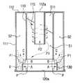
도 3은 도 1의 사이클론 집진장치의 부분절개도,3 is a partial cutaway view of the cyclone dust collector of FIG.
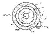
도 4은 도 1의 단면 Ⅳ-Ⅳ를 나타낸 도면,4 is a view showing a cross-section IV-IV of FIG.
도 5는 도 1의 단면 Ⅴ-Ⅴ를 나타낸 도면,5 is a view showing a cross-section V-V of FIG.
도 6은 도 2의 상부커버 및 역류방지턱을 나타낸 사시도.6 is a perspective view of the upper cover and the non-return jaw of Figure 2;
도 7은 도 1의 사이클론 집진장치가 뒤집어진 도면이다.7 is a view in which the cyclone dust collector of FIG. 1 is turned upside down.
< 도면의 주요부분에 대한 부호의 설명 ><Description of Symbols for Major Parts of Drawings>
100..사이클론 집진장치 110..사이클론몸체100
111..외벽 112..저벽111..
113..내벽 115..배기파이프113..
117..유입파이프 120..상부커버117.
130..역류방지턱 S1..사이클론실130. Backflow prevention S1. Cyclone room
S2..오물수거실 S11..가이드S2..Waste collection room S11..Guide
P..연결통로 P1..보조통로P. Connecting passage P1. Secondary passage
본 발명은 진공청소기에 장착되며, 유입된 집진공기를 먼지와 공기로 원심분리하는 사이클론 집진장치에 관한 것이다.The present invention is mounted on a vacuum cleaner, and relates to a cyclone dust collector for centrifuging the introduced dust collector with dust and air.
이러한 사이클론 집진장치의 초기모델은 미국등록특허(US6003196)에 개시된 바와 같이 먼지의 분리와 수집이 같은 장소에서 일어난다. 이 경우 수거된 먼지는 사이클론 기류로 인해 비산되거나 배기파이프로 다시 역류될 수 있어 먼지의 분리효율이 떨어지고, 역류된 먼지로 인해 배기필터와 같은 각종 필터가 막히는 문제점이 발생한다. 특히, 이러한 문제점은 청소도중 진공청소기가 뒤집어져, 수거된 먼지가 쏟아질 경우 더 크게 발생한다.The initial model of such cyclone dust collector is a separation and collection of dust occurs in the same place as disclosed in the US Patent (US6003196). In this case, the collected dust may be scattered due to the cyclone airflow or flow back to the exhaust pipe, thereby reducing the separation efficiency of the dust and clogging various filters such as the exhaust filter due to the reversed dust. In particular, this problem occurs more seriously when the vacuum cleaner is turned upside down during cleaning and the collected dust is poured out.
한편, 이러한 문제점을 해결하기 위하여 본 출원인의 선출원인 한국공개특허(KR2002-0009768)에 개시된 바와 같은 사이클론 집진장치가 창안되었다. 즉, 이러한 사이클론 집진장치는 원통형의 사이클론몸체와, 이러한 사이클론몸체의 외측을 원주상으로 감싸며 먼지의 이동을 한정하는 칸막이를 포함한 통형의 오물수거통과, 상기 사이클론몸체와 오물수거통을 상측에서 덮는 공기유입구와 공기배출구를 가지는 커버로 구성되며, 캐니스터형 청소기에 적용되기 위해 소형으로 제작된다.On the other hand, in order to solve this problem, a cyclone dust collector as disclosed in the Korean Laid-Open Patent Application (KR2002-0009768), the applicant of the present applicant has been created. That is, the cyclone dust collecting device has a cylindrical cyclone body, a cylindrical waste container including a partition that surrounds the outer side of the cyclone body in a circumferential manner and restricts the movement of dust, and an air inlet covering the cyclone body and the waste container from above. It is composed of a cover having an air outlet and is made compact to be applied to the canister cleaner.
그러나, 이와 같은 사이클론 집진장치가 청소 도중 자주 뒤집어지는 캐니스터형 청소기에 설치된 경우, 사이클론몸체 내부에 남아있는 먼지가 공기배출구가 형성되어 있는 커버로 쏟아져 공기배출구를 통해 사이클론 집진장치를 빠져나갈 수 있다.However, when such a cyclone dust collector is installed in a canister cleaner that is frequently turned over during cleaning, the dust remaining inside the cyclone body may be poured into a cover in which an air outlet is formed to exit the cyclone dust collector through the air outlet.
또한, 커버에 공기유입구와 공기배출구가 동시에 형성되어 있어 커버의 구성이 복잡하다.In addition, since the air inlet and the air outlet are formed in the cover at the same time, the configuration of the cover is complicated.
본 발명은 상기와 같은 문제점을 해결하기 위해 창안된 것으로, 진공청소기가 뒤집어지더라도, 수거된 먼지의 역류가 방지된 사이클론 집진장치를 제공하는데 목적이 있다.The present invention has been made to solve the above problems, and an object of the present invention is to provide a cyclone dust collector which prevents reverse flow of collected dust even when the vacuum cleaner is turned upside down.
본 발명의 다른 목적은 커버의 구성이 간단한 사이클론 집진장치를 제공하는데 있다.It is another object of the present invention to provide a cyclone dust collector having a simple cover configuration.
상기 목적을 달성하기 위한 본 발명에 따른 사이클론 집진장치는, 사이클론실 및 상기 사이클론실의 외측을 원주상으로 감싸는 오물수거실을 포함한 사이클론몸체; 상기 사이클론실 및 상기 오물수거실 사이의 연결통로를 형성하도록, 상기 사이클론몸체의 상단에 설치되는 상부커버; 및 상기 상부커버의 내벽에 형성되어 상기 오물수거실로부터 상기 사이클론실로 오물이 역류되는 것을 차단하는 역류방지턱;을 포함하는 것을 특징으로 한다.Cyclone dust collecting apparatus according to the present invention for achieving the above object, Cyclone body including a cyclone chamber and a waste collection chamber circumferentially surrounding the outer side of the cyclone chamber; An upper cover installed at an upper end of the cyclone body to form a connection passage between the cyclone chamber and the waste collection chamber; And a backflow prevention jaw formed on an inner wall of the upper cover to block backflow of dirt from the waste collection chamber to the cyclone chamber.
여기서, 상기 사이클론 집진장치는, 상기 사이클론몸체의 저벽에 설치된 배기파이프; 상기 사이클론몸체의 내벽 및 외벽을 관통하도록, 상기 사이클론몸체의 하부에 설치된 유입파이프; 및 상기 유입파이프로부터 유입되는 공기를 안내하도록, 상기 사이클론실에 설치된 가이드;를 더 포함하는 것이 바람직하다.Here, the cyclone dust collector includes an exhaust pipe provided on the bottom wall of the cyclone body; An inlet pipe installed under the cyclone body to penetrate the inner and outer walls of the cyclone body; And a guide installed in the cyclone chamber to guide the air introduced from the inlet pipe.
상기 역류방지턱은, 상기 사이클론실의 외경(D1)보다 큰 외경(D2)을 가진 원주형의 돌기이며, 상기 역류방지턱의 높이(H3)는, 상기 연결통로의 높이(H4)보다 낮은 것이 바람직하다.The backflow prevention jaw is a columnar protrusion having an outer diameter D2 larger than the outer diameter D1 of the cyclone chamber, and the height H3 of the backflow prevention jaw is lower than the height H4 of the connection passage. .
또한, 상기 목적은 원형의 내벽, 상기 내벽과 일정공간을 두고 이격되어 설치된 외벽, 상기 내벽과 외벽을 연결하는 저벽 및 상기 외벽의 상단과 연결된 상벽을 포함한 사이클론몸체; 상기 사이클론몸체의 외벽 및 내벽을 관통하는 유입파이프; 상기 사이클론몸체의 저벽을 관통하는 배기파이프; 및 상기 상벽의 저면으로부터 하방향으로 돌출된 오물방지턱;을 포함하며, 상기 내벽의 상단과 상기 상벽의 저면이 일정간격으로 이격된 사이클론 집진장치에 의해 달성된다. 여기서, 상기 역류방지턱은, 상기 원형의 내벽 보다 큰 지름을 갖는 것이 바람직하다.In addition, the object includes a cyclone body including a circular inner wall, an outer wall spaced apart from the inner wall with a predetermined space, a bottom wall connecting the inner wall and the outer wall, and an upper wall connected to an upper end of the outer wall; An inlet pipe penetrating the outer wall and the inner wall of the cyclone body; An exhaust pipe passing through the bottom wall of the cyclone body; And a dirt preventing protrusion protruding downward from the bottom of the upper wall, wherein the upper end of the inner wall and the bottom of the upper wall are separated by a cyclone dust collector spaced at a predetermined interval. Here, the backflow prevention jaw preferably has a larger diameter than the circular inner wall.
이하, 첨부된 도면을 참조하여 본 발명의 바람직한 실시예에 따른 사이클론 집진장치를 상세히 설명하기로 한다.Hereinafter, a cyclone dust collector according to a preferred embodiment of the present invention with reference to the accompanying drawings will be described in detail.
도 1은 본 발명인 사이클론 집진장치의 일 실시예가 적용된 진공청소기를 나타낸 도면이다. 도 1을 참조하면, 진공청소기(10)는 청소기본체(11)와, 연장관(12) 과, 플랙시블호스(13)와, 연장관(12) 및 플랙시블호스(13)를 통해 청소기본체(11)와 연결된 흡입브러쉬(14)와, 청소기본체(11)에 착탈가능하게 설치된 사이클론 집진장치(100)를 포함한다.1 is a view showing a vacuum cleaner to which an embodiment of the cyclone dust collector of the present invention is applied. Referring to FIG. 1, the
청소기본체(11)의 전면에는 사이클론 집진장치(100)의 공기흡입구(117a)와 연통되는 연결공(11b)이 형성되며, 이러한 연결공(11b)에 플랙시블호스(13)가 장착된다.A
그리고, 이러한 청소기본체(11)내에는 사이클론 집진장치(100)가 안착되는 집진실(11a)이 마련되며, 이러한 집진실(11a)에는 사이클론 집진장치(100)가 얹혀질 수 있는 배기필터(15)가 설치된다. 이러한 배기필터(15)를 통해 사이클론 집진장치(100)의 공기배출구(112a, 도 4참조)와 청소기본체(11)내 설치된 흡입원(미도시)이 연통된다.In addition, a
도 2를 참조하면, 사이클론 집진장치(100)는 사이클론몸체(110)와, 상부커버(120)와, 역류방지턱(130)을 포함한다.Referring to FIG. 2, the cyclone
사이클론몸체(110)는 원통형의 용기로서, 중심부에 사이클론실(S1)이 형성되며, 원주상에 오물수거실(S2)이 형성된다. 이를 위해 사이클론몸체(110)는 외벽(111)과 저벽(112, 도 3참조)과 내벽(113)을 포함한다.The
도 3 및 도 4를 참조하면, 사이클론실(S1)은 내벽(113)과 저벽(112)에 의해 형성되며, 집진공기로부터 먼지(X)가 원심분리되는 공간이다. 이때, 내벽(113)의 높이(H2)는 사이클론실(S1)과 오물수거실(S2)사이에 높이가 H4인 띠형의 연결통로(P)를 형성하기 위해 외벽(111)의 높이(H1)보다 작아야 한다. 참고적으로 도 4에 표시된 점선은 연결통로(P)가 형성되는 공간을 보다 명확하게 표시하기 위한 보조선이다.3 and 4, the cyclone chamber S1 is formed by the
사이클론실(S1)의 저벽(112)에는 배기파이프(115)를 나선형으로 감싸며 점차 높아져 최고 높이가 H6인 가이드(S11)가 설치된다. 이러한 가이드(S11)에 의해 유입파이프(117)로부터 유입된 집진공기가 회전력을 유지하면서 상부커버(120) 방향으로 유도된다. 한편, 이러한 가이드(S11)는 사이클론몸체(110)의 저벽(112)으로부 터 직접 형성할 수 있으며, 필요에 따라서는 별개의 구조물로 제작하여 저벽(112)에 용접 또는 접착될 수도 있다.In the
도 3을 참조하면, 유입파이프(117)가 외벽(111) 및 내벽(113)을 관통하여 사이클론몸체(110)의 하부에 설치된다. 보다 구체적으로 이러한 유입파이프(117)는 집진공기에 원심력을 부여하기 위해 도 5에 도시된 바와 같이 사이클론실(S1)의 측방향에 설치되며, 이러한 유입파이프(117)는 원형외에 사각, 삼각등 다양한 형태로 구성될 수 있다. 이러한 유입파이프(117)를 통해 공기흡입구(117a)를 통해 유입된 집진공기가 사이클론실(S1)로 안내된다.Referring to FIG. 3, an
도 4를 참조하면, 사이클론실(S1)의 저벽(112) 중심부에는 공기배출구(112a)가 형성되며, 이러한 공기배출구(112a)에는 소정 높이(H5)를 가진 배기파이프(115)가 용접 또는 접착되어 설치된다.Referring to FIG. 4, an
한편, 배기파이프(115)의 높이(H5)는 유입파이프(117)로 들어온 집진공기가 곧바로 배출되지 않으면서, 집진공기로부터 분리된 공기가 원할하게 빠져나갈 수 있는 높이(H5)를 가져야 한다. 실험에 의하면, 이러한 배기파이프(115)의 높이(H5)는 다음과 같은 계산식에 의해 구해진다.On the other hand, the height (H5) of the
H5=H6+(H2-H6)*1/3H5 = H6 + (H2-H6) * 1/3
즉, 내벽(113)의 높이(H2)에서 가이드(S11)의 최고 높이(H6)를 뺀 후 1/3을 곱한다. 그리고, 이렇게 계산된 높이(H2-H6)에 가이드(S11)의 최고 높이(H6)를 더하면, 바람직한 배기파이프(115)의 높이(H5)가 계산된다. 다만, 곱하는 계수가 반드시 1/3일 필요는 없으며, 대략 1/3 ~ 1/2 사이에 있으면 무관하다.That is, the height H2 of the
그리고, 이러한 배기파이프(115)는 몰딩물로 사이클론실(S1)의 저벽(112)과 일체로 형성할 수 있으며, 형상도 원형외에 사각, 삼각등 다양한 형태로 구성할 수 있다. 이러한 공기배출구(112a) 및 배기파이프(115)를 통해 집진공기로부터 분리된 공기가 화살표 F2방향으로 사이클론 집진장치(100)를 빠져나가게 된다.The
도 4 및 도 5를 참조하면, 오물수거실(S2)은 사이클론실(S1)의 외측을 감싸도록 형성된 공간으로, 이러한 오물수거실(S2)로 먼지(X)가 수집된다. 이를 위해 오물수거실(S2)은 내벽(113), 외벽(111), 저벽(112)에 둘러쌓여 형성된다.4 and 5, the waste collection chamber S2 is a space formed to surround the outside of the cyclone chamber S1, and the dust X is collected into the waste collection chamber S2. To this end, the waste collection chamber S2 is formed surrounded by the
상술한 바와 같이, 사이클론실(S1)과 오물수거실(S2)이 분리되어 있어 먼지(X)의 분리와 수거가 별개의 장소에서 일어난다. 따라서, 도 7에 도시된 바와 같이 진공청소기가 뒤집어져 먼지(X)가 상부커버(120)의 하면(120a)으로 쏟아질 경우도 오물수거실(S2)에 수거된 먼지(X)가 사이클론실(S1)로 역류하는 것이 방지된다. 그리고, 먼지(X)의 수거와 분리가 다른 장소에서 일어나 수거된 먼지(X)가 비산되거나 역류되는 것이 방지된다.As described above, the cyclone chamber S1 and the waste collection chamber S2 are separated, so that the separation and collection of the dust X take place in separate places. Therefore, even when the vacuum cleaner is turned over as shown in FIG. 7 and the dust X is poured into the
한편, 공기흡입구(117a)와 공기배출구(112a)가 각각 사이클론몸체(110)의 외벽(111)과 저벽(112)에 형성된 관계로 상부커버(120)의 구성이 간단해진다.On the other hand, since the
또한, 배기파이프(115)가 저벽(112)에 설치된 관계로 진공청소기(10)가 청소도중 뒤집어지더라도 사이클론실(S1)에 남아있는 먼지가 배기파이프(115)를 통해 공기배출구(112a)로 빠져나가는 것이 방지된다.In addition, since the
도 4 내지 도 6을 참조하면, 상기 상부커버(120)는 사이클론몸체(110)의 상측에 결합되는 원형의 덮개이다. 이러한 상부커버(120)가 사이클론몸체(110)의 상 측에 결합됨으로서 연결통로(P)가 비로서 형성된다.4 to 6, the
다만, 본 실시예와 달리 사이클론몸체(110)의 상측을 상부커버(120) 대신, 외벽(111)의 상단과 연결된 분리되지 않는 상벽으로 덮을 수도 있다. 이 경우 오물수거실(S2)에 수거된 먼지는 저벽(112)을 개폐 가능하게 하여 버릴 수 있을 것이다.However, unlike the present embodiment, instead of the
상기 역류방지턱(130)은 상부커버(120)의 하면(120a)에 형성된 원주형의 돌기로서 연결통로(P)의 일부를 차단한다. 역류방지턱(130)의 높이(H3)는 상부커버(120)가 사이클론몸체(110)에 결합시 연결통로(P)의 높이(H4)보다 작게 형성되며, 이렇게 함으로서 역류방지턱(130)이 연결통로(P)을 부분적으로 차단하여 띠형의 보조통로(P1)가 형성된다.The
이러한, 보조통로(P1)를 통해 사이클론실(S1)에서 원심분리된 먼지(X)가 오물수거실(S2)내로 떨어지게 된다. 참고적으로, 점선은 보조통로(P1)가 형성되는 공간을 보다 명확하게 표시하기 위한 보조선이다.The dust (X) centrifuged in the cyclone chamber (S1) through the auxiliary passage (P1) is dropped into the waste collection chamber (S2). For reference, the dotted line is an auxiliary line for more clearly indicating the space in which the auxiliary passage P1 is formed.
역류방지턱(130)은 사이클론실(S1)의 외경(D1)보다 큰 외경(D2)을 가진다. 이렇게 함으로서 집진공기로부터 원심분리된 먼지(X)가 화살표 A방향으로 역류방지턱(130)에 부딪친 후 화살표 C방향인 수직방향으로 보조통로(P1)를 통해 사이클론실(S1)이 아닌 오물수거실(S2)로 떨어진다.The
또한, 원심분리된 먼지(X)를 운반하는 기류가 화살표 A방향으로 역류방지턱(130)에 부딪친 후 화살표 C방향인 수직방향으로, 사이클론실(S1)이 아닌 오물수거실(S2)로 하강한다. 이렇게 수직하게 하강하는 기류로 인해, 도 7에 도시된 바와 같이 진공청소기가 뒤집어져 먼지(X)가 상부커버(120)의 하면(120a)으로 쏟아질 경우에 오물수거실(S2)에 수거된 먼지(X)가 사이클론실(S1)로 역류하는 것이 방지된다.In addition, the air stream carrying the centrifuged dust (X) hits the
그리고, 수거된 먼지(X)가 비산되거나 역류되는 것이 방지된다. 즉, 오물수거실(S2)에 수거된 먼지(X)가 상부커버(120)방향으로 상승하려고 해도, 수직으로 하강하는 기류로 인해 오물수거실(S2)내로 다시 밀려 내려가게 된다. 이렇게 먼지(X)가 떨어지는 과정과 기류가 하강하는 과정은 순차적 또는 동시에 일어날 수 있다.Then, the collected dust X is prevented from scattering or flowing back. That is, even if the dust (X) collected in the waste collection chamber (S2) tries to rise in the direction of the
결과적으로, 도 7에 도시된 바와 같이 진공청소기가 뒤집어져 먼지(X)가 상부커버(120)의 하면(120a)으로 쏟아지더라도, 사이클론실(S1)과 오물수거실(S2)이 분리되어 있어 오물수거실(S2)에 수거된 먼지(X)가 사이클론실(S1)로 역류하는 것이 1차적으로 방지되며, 역류방지턱(130)에 의해 형성된 수직 하강기류로 인해 보조통로(P1)를 통해 오물수거실(S2)에 수거된 먼지(X)가 사이클론실(S1)로 역류하는 것이 2차적으로 방지된다.As a result, even if the vacuum cleaner is turned over as shown in FIG. 7 and the dust X is poured into the
또한, 배기파이프(115)가 저벽(112)에 설치된 관계로 진공청소기(10)가 청소도중 뒤집어지더라도 사이클론실(S1)에 남아있는 먼지가 배기파이프(115)를 통해 공기배출구(112a)로 빠져나가는 것이 방지된다.In addition, since the
이하, 상기와 같은 구성을 가진 사이클론 집진장치(100)의 동작을 설명하면 다음과 같다.Hereinafter, the operation of the
도 1을 참조하면, 진공청소기(10)가 구동되면 흡입원(미도시)에 의해 제공된 흡입력에 의해 흡입브러쉬(14)로 피청소면의 먼지(X)가 흡입된다. 이렇게 흡입된 먼지(X)는 화살표 F1방향으로 연장관(12) 및 플랙시블호스(13)를 거쳐 청소기본체(11)의 연결공(11b)과 연통된 공기흡입구(117a)를 통해 사이클론 집진장치(100)로 유입된다.Referring to FIG. 1, when the
도 3을 참조하면, 이렇게 유입된 먼지(X)는 유입파이프(117)를 거쳐 사이클론실(S1) 내부로 유입된다. 이때, 먼지(X)는 유입파이프(117)가 사이클론실(S1)의 저벽(112)에 측방향에 설치된 관계로 원심력을 부여받게 된다. 또한, 가이드(S11)가 배기파이프(115)를 나선형으로 감싸며 점차 높아지게 사이클론실(S1)의 저벽(112)에 설치된 관계로 원심력을 유지하면서 상부커버(120) 방향으로 유도된다.Referring to FIG. 3, the dust X thus introduced is introduced into the cyclone chamber S1 through the
도 4를 참조하면, 이러한 과정을 통해 공기속에 포함된 먼지(X)는 원심분리되면서 연결통로(P)로 튕겨져 나간다. 연결통로(P)로 튕겨져 나간 먼지(X)는 화살표 A방향으로 역류방지턱(130)과 부딪친 후 화살표 C방향으로 수직하게 연결통로(P)의 보조통로(P1)을 거쳐 오물수거실(S2)로 떨어진다. 또한 화살표 B방향으로 직접 연결통로(P)의 보조통로(P1)을 거쳐 오물수거실(S2)로 떨어질 수도 있다.Referring to Figure 4, through this process, the dust (X) contained in the air is bounced out into the connecting passage (P) while being centrifuged. The dust (X) bounced off by the connecting passage (P) hits the backflow prevention projection (130) in the direction of arrow A, and then goes through the auxiliary passage (P1) of the connecting passage (P) vertically in the direction of the arrow C (S2). Falls into. In addition, it may fall to the waste collection chamber (S2) via the auxiliary passage (P1) of the direct connection passage (P) in the arrow B direction.
이와 동시에 또는 순차적으로, 원심분리된 먼지(X)를 운반하는 기류는 화살표 A방향으로 역류방지턱(130)과 부딪쳐 화살표 C방향으로 수직하게 연결통로(P)의 보조통로(P1)를 거쳐 오물수거실(S2)로 하강하게 된다. 이렇게 하강하는 기류에 의해 오물수거실(S2)에 수거된 먼지(X)가 상부커버(120)로 상승되는 것이 억제된다.At the same time or sequentially, the airflow carrying the centrifuged dust X collides with the
이후, 먼지(X)가 제거된 공기는 화살표 F2방향으로 배기파이프(115), 공기배출구(112a)를 거쳐 사이클론 집진장치(100)를 빠져나간 후 배기필터(15, 도 1참조 ), 흡입원(미도시)을 거쳐 진공청소기(10, 도 1참조)를 빠져나가게 된다.Thereafter, the air from which the dust (X) has been removed passes through the
이상에서 설명한 본 발명의 실시예에 의한 사이클론 집진장치에 따르면,According to the cyclone dust collector according to the embodiment of the present invention described above,
첫째, 역류방지턱과 사이클론실 및 오물수거실이 분리되어 있어 진공청소기가 청소도중 뒤집어지더라도 오물수거실에 수거된 먼지가 역류되지 않으며, 오물수거실에 수거된 먼지의 비산 및 역류가 방지된다. 따라서, 배기필터와 같은 각종 필터가 막히는 것이 방지된다.First, since the backflow prevention jaw, the cyclone chamber, and the waste collection chamber are separated, the dust collected in the waste collection chamber does not flow back even when the vacuum cleaner is turned over during the cleaning, and the scattering and backflow of the dust collected in the waste collection chamber is prevented. Therefore, clogging of various filters such as the exhaust filter is prevented.
둘째, 배기파이프가 저벽에 설치된 관계로 진공청소기가 청소도중 뒤집어지더라도 사이클론실에 남아있는 먼지가 배기파이프를 통해 공기배출구로 빠져나가는 것이 방지된다. 따라서, 배기필터와 같은 각종 필터가 막히는 것이 방지된다.Second, since the exhaust pipe is installed on the bottom wall, even if the vacuum cleaner is turned over during cleaning, the dust remaining in the cyclone chamber is prevented from escaping through the exhaust pipe to the air outlet. Therefore, clogging of various filters such as the exhaust filter is prevented.
셋째, 공기유입구는 사이클론몸체의 외벽에 형성되고, 공기배출구는 저벽에 형성된 관계의 커버의 구성이 간단해 제작이 용이하며, 수거된 먼지를 배출하기 위해 단순한 구성을 가진 커버를 열면 되므로 편리하다.Third, the air inlet is formed on the outer wall of the cyclone body, the air outlet is easy to manufacture because of the simple configuration of the cover formed on the bottom wall, it is convenient because the cover having a simple configuration to discharge the collected dust.
이상, 본 발명의 원리를 예시하기 위한 바람직한 실시 예와 관련하여 설명하고 도시하였으나, 본 발명은 그와 같이 도시되고 설명된 그대로의 구성 및 작용으로 한정되는 것이 아니다. 오히려 첨부된 특허청구범위의 사상 및 범주를 일탈함이 없이 본 발명에 대한 다수의 변경 및 수정이 가능함을 당업자들은 잘 이해할 수 있을 것이다. 따라서, 그러한 모든 적절한 변경 및 수정과 균등물들도 본 발명의 범위에 속하는 것으로 간주되어야 할 것이다.As described above and described with reference to a preferred embodiment for illustrating the principle of the present invention, the present invention is not limited to the configuration and operation as shown and described as such. Rather, those skilled in the art will appreciate that many modifications and variations of the present invention are possible without departing from the spirit and scope of the appended claims. Accordingly, all such suitable changes and modifications and equivalents should be considered to be within the scope of the present invention.
Claims (6)
Translated fromKoreanPriority Applications (8)
| Application Number | Priority Date | Filing Date | Title |
|---|---|---|---|
| KR1020050003688AKR100560967B1 (en) | 2005-01-14 | 2005-01-14 | A cyclone dust-separating apparatus |
| US11/128,662US7422615B2 (en) | 2005-01-14 | 2005-05-13 | Cyclone dust-separating apparatus |
| JP2005144642AJP2006192247A (en) | 2005-01-14 | 2005-05-17 | Cyclone dust collector |
| EP05291199AEP1681099B1 (en) | 2005-01-14 | 2005-06-03 | A cyclone dust-separating apparatus for vacuum cleaner |
| DE602005024505TDE602005024505D1 (en) | 2005-01-14 | 2005-06-03 | Cyclone separator for vacuum cleaners |
| CNB2005100763174ACN100341457C (en) | 2005-01-14 | 2005-06-15 | Cyclone dust-separating apparatus |
| RU2005118811/12ARU2296500C2 (en) | 2005-01-14 | 2005-06-17 | Cyclone dust separator |
| AU2005203524AAU2005203524B2 (en) | 2005-01-14 | 2005-08-08 | A cyclone dust-separating apparatus |
Applications Claiming Priority (1)
| Application Number | Priority Date | Filing Date | Title |
|---|---|---|---|
| KR1020050003688AKR100560967B1 (en) | 2005-01-14 | 2005-01-14 | A cyclone dust-separating apparatus |
Publications (1)
| Publication Number | Publication Date |
|---|---|
| KR100560967B1true KR100560967B1 (en) | 2006-03-15 |
Family
ID=36128485
Family Applications (1)
| Application Number | Title | Priority Date | Filing Date |
|---|---|---|---|
| KR1020050003688AExpired - LifetimeKR100560967B1 (en) | 2005-01-14 | 2005-01-14 | A cyclone dust-separating apparatus |
Country Status (8)
| Country | Link |
|---|---|
| US (1) | US7422615B2 (en) |
| EP (1) | EP1681099B1 (en) |
| JP (1) | JP2006192247A (en) |
| KR (1) | KR100560967B1 (en) |
| CN (1) | CN100341457C (en) |
| AU (1) | AU2005203524B2 (en) |
| DE (1) | DE602005024505D1 (en) |
| RU (1) | RU2296500C2 (en) |
Cited By (6)
| Publication number | Priority date | Publication date | Assignee | Title |
|---|---|---|---|---|
| KR100783143B1 (en) | 2007-02-05 | 2007-12-07 | 삼성광주전자 주식회사 | Cyclone Dust Collector for Vacuum Cleaner |
| WO2007145404A1 (en) | 2006-06-16 | 2007-12-21 | Samsung Gwangju Electronics Co., Ltd. | Dust collecting apparatus for vacuum cleaner |
| KR100831346B1 (en) | 2006-12-28 | 2008-05-22 | 삼성광주전자 주식회사 | Vacuum cleaner |
| US7662202B2 (en) | 2006-06-19 | 2010-02-16 | Samsung Gwangju Electronics Co., Ltd. | Dust collector of vacuum cleaner |
| KR101471026B1 (en)* | 2008-03-05 | 2014-12-11 | 삼성전자주식회사 | Vacuum cleaner for optional dust bag or cyclone dust collector |
| KR20160119602A (en)* | 2015-04-06 | 2016-10-14 | 엘지전자 주식회사 | Dust collecting apparatus and Vacuum cleaner having thereof |
Families Citing this family (98)
| Publication number | Priority date | Publication date | Assignee | Title |
|---|---|---|---|---|
| KR100626736B1 (en)* | 2005-07-12 | 2006-09-25 | 삼성광주전자 주식회사 | Dust collector of vacuum cleaner |
| US7645311B2 (en)* | 2005-07-12 | 2010-01-12 | Samsung Gwangju Electronics Co., Ltd. | Cyclone unit and contaminants-collecting apparatus having the same |
| KR101003417B1 (en)* | 2005-08-17 | 2010-12-23 | 엘지전자 주식회사 | Dust collector of vacuum cleaner |
| KR100714493B1 (en)* | 2005-10-14 | 2007-05-07 | 삼성광주전자 주식회사 | Dust collector of vacuum cleaner |
| US20070144116A1 (en)* | 2005-12-23 | 2007-06-28 | Samsung Electronics Co., Ltd. | Cyclonic cleaner |
| GB2436308A (en)* | 2006-03-23 | 2007-09-26 | Adrian Christopher Arnold | Particle separator |
| KR100706622B1 (en)* | 2006-05-03 | 2007-04-13 | 삼성광주전자 주식회사 | Compact Dual Cyclone Dust Collector for Vacuum Cleaners |
| AU2007200172B2 (en)* | 2006-06-19 | 2008-09-25 | Samsung Electronics Co., Ltd. | Dust collector of vacuum cleaner |
| GB2440125A (en)* | 2006-07-18 | 2008-01-23 | Dyson Technology Ltd | Cyclonic separating apparatus |
| US12220099B2 (en) | 2006-12-12 | 2025-02-11 | Omachron Intellectual Property Inc. | Surface cleaning apparatus |
| US8950039B2 (en) | 2009-03-11 | 2015-02-10 | G.B.D. Corp. | Configuration of a surface cleaning apparatus |
| US10765277B2 (en) | 2006-12-12 | 2020-09-08 | Omachron Intellectual Property Inc. | Configuration of a surface cleaning apparatus |
| CN101626715B (en) | 2006-12-12 | 2012-07-25 | Gbd公司 | Convertible surface cleaning apparatus |
| KR100776403B1 (en)* | 2007-02-14 | 2007-11-16 | 삼성광주전자 주식회사 | Cyclone Dust Collector for Vacuum Cleaner |
| GB2447039B (en)* | 2007-02-27 | 2011-12-28 | Bioflame Ltd | Residence chamber for products of combustion |
| US11751733B2 (en) | 2007-08-29 | 2023-09-12 | Omachron Intellectual Property Inc. | Portable surface cleaning apparatus |
| US12048409B2 (en) | 2007-03-11 | 2024-07-30 | Omachron Intellectual Property Inc. | Portable surface cleaning apparatus |
| KR100816910B1 (en)* | 2007-04-12 | 2008-03-25 | 엘지전자 주식회사 | Dust separator of vacuum cleaner |
| CN201123782Y (en)* | 2007-04-03 | 2008-10-01 | 苏州金莱克家用电器有限公司 | Dust removing device for dust aspirator |
| CN101332066B (en)* | 2007-06-25 | 2011-05-11 | 乐金电子(天津)电器有限公司 | Dust collection tube with tri-level cyclone structure |
| US20100175217A1 (en)* | 2007-08-29 | 2010-07-15 | G.B.D. Corp. | Cyclonic surface cleaning apparatus with externally positioned dirt chamber |
| GB2455535A (en)* | 2007-12-12 | 2009-06-17 | Prime Sourcing Ltd | Cyclone chamber with vortex shield |
| CN101939110B (en)* | 2007-12-19 | 2015-01-21 | Gbd公司 | Structure of cyclone separator assembly and surface cleaning device having said cyclone separator assembly |
| KR101472835B1 (en)* | 2008-02-15 | 2014-12-17 | 삼성전자주식회사 | Cyclone dust collectors for vacuum cleaners |
| US20100089014A1 (en)* | 2008-10-15 | 2010-04-15 | Changzhou Shinri Household Appliance Manufacturing Co., Ltd. | Cyclonic separation device for vacuum cleaner |
| US8062398B2 (en)* | 2008-12-19 | 2011-11-22 | Bissell Homecare, Inc. | Vacuum cleaner and cyclone module therefor |
| DE102008055046B3 (en)* | 2008-12-19 | 2010-06-17 | BSH Bosch und Siemens Hausgeräte GmbH | Vacuum cleaner with a centrifugal separator |
| KR101542185B1 (en)* | 2008-12-29 | 2015-08-07 | 삼성전자주식회사 | Vacuum cleaner having detachable dust-separating dpparatus |
| CA2674761C (en) | 2009-03-13 | 2016-10-04 | G.B.D. Corp. | Surface cleaning apparatus with different cleaning configurations |
| US9198551B2 (en) | 2013-02-28 | 2015-12-01 | Omachron Intellectual Property Inc. | Surface cleaning apparatus |
| CA2674376A1 (en) | 2009-03-13 | 2010-09-13 | G.B.D. Corp. | Surface cleaning apparatus with different cleaning configurations |
| US11690489B2 (en) | 2009-03-13 | 2023-07-04 | Omachron Intellectual Property Inc. | Surface cleaning apparatus with an external dirt chamber |
| US11612288B2 (en) | 2009-03-13 | 2023-03-28 | Omachron Intellectual Property Inc. | Surface cleaning apparatus |
| US9138114B2 (en) | 2009-03-13 | 2015-09-22 | Omachron Intellectual Property Inc. | Surface cleaning apparatus |
| US9591953B2 (en) | 2009-03-13 | 2017-03-14 | Omachron Intellectual Property Inc. | Surface cleaning apparatus |
| US9480373B2 (en) | 2009-03-13 | 2016-11-01 | Omachron Intellectual Property Inc. | Surface cleaning apparatus |
| US9427122B2 (en) | 2009-03-13 | 2016-08-30 | Omachron Intellectual Property Inc. | Surface cleaning apparatus |
| US9392916B2 (en) | 2009-03-13 | 2016-07-19 | Omachron Intellectual Property Inc. | Surface cleaning apparatus |
| CA2967272C (en) | 2009-03-13 | 2018-01-02 | Omachron Intellectual Property Inc. | Hand vacuum cleaner |
| US9211044B2 (en) | 2011-03-04 | 2015-12-15 | Omachron Intellectual Property Inc. | Compact surface cleaning apparatus |
| US9226633B2 (en) | 2009-03-13 | 2016-01-05 | Omachron Intellectual Property Inc. | Surface cleaning apparatus |
| AU2010214785B2 (en)* | 2009-09-10 | 2014-06-12 | Bissell Inc. | Extraction cleaner and centrifugal air/water separator therefor |
| US8875340B2 (en) | 2010-03-12 | 2014-11-04 | G.B.D. Corp. | Surface cleaning apparatus with enhanced operability |
| US8152877B2 (en)* | 2010-03-12 | 2012-04-10 | Euro-Pro Operating Llc | Shroud for a cleaning service apparatus |
| USD676620S1 (en)* | 2011-02-03 | 2013-02-19 | Jayd Allen Lindom | Debris collection vacuum attachment |
| US8997309B2 (en)* | 2012-03-02 | 2015-04-07 | G.B.D. Corp. | Surface cleaning apparatus |
| JP5370548B1 (en)* | 2012-07-18 | 2013-12-18 | 三菱電機株式会社 | Cyclone separation device and vacuum cleaner |
| JP5333633B1 (en)* | 2012-08-02 | 2013-11-06 | 三菱電機株式会社 | Electric vacuum cleaner |
| KR101397054B1 (en)* | 2012-08-31 | 2014-05-20 | 엘지전자 주식회사 | vacuum cleaner |
| JP5472417B1 (en)* | 2012-09-28 | 2014-04-16 | 三菱電機株式会社 | Centrifuge |
| US9820621B2 (en) | 2013-02-28 | 2017-11-21 | Omachron Intellectual Property Inc. | Surface cleaning apparatus |
| US9326652B2 (en) | 2013-02-28 | 2016-05-03 | Omachron Intellectual Property Inc. | Surface cleaning apparatus |
| US9227201B2 (en)* | 2013-02-28 | 2016-01-05 | Omachron Intellectual Property Inc. | Cyclone such as for use in a surface cleaning apparatus |
| US9227151B2 (en) | 2013-02-28 | 2016-01-05 | Omachron Intellectual Property Inc. | Cyclone such as for use in a surface cleaning apparatus |
| US9314138B2 (en) | 2013-02-28 | 2016-04-19 | Omachron Intellectual Property Inc. | Surface cleaning apparatus |
| US9238235B2 (en)* | 2013-02-28 | 2016-01-19 | Omachron Intellectual Property Inc. | Cyclone such as for use in a surface cleaning apparatus |
| US9451855B2 (en) | 2013-02-28 | 2016-09-27 | Omachron Intellectual Property Inc. | Surface cleaning apparatus |
| US9215960B2 (en) | 2013-02-28 | 2015-12-22 | Omachron Intellectual Property Inc. | Surface cleaning apparatus |
| US20140237764A1 (en) | 2013-02-28 | 2014-08-28 | G.B.D. Corp. | Cyclone such as for use in a surface cleaning apparatus |
| US9456721B2 (en) | 2013-02-28 | 2016-10-04 | Omachron Intellectual Property Inc. | Surface cleaning apparatus |
| US9364127B2 (en) | 2013-02-28 | 2016-06-14 | Omachron Intellectual Property Inc. | Surface cleaning apparatus |
| US9295995B2 (en)* | 2013-02-28 | 2016-03-29 | Omachron Intellectual Property Inc. | Cyclone such as for use in a surface cleaning apparatus |
| CN203341657U (en)* | 2013-04-11 | 2013-12-18 | 江苏美的春花电器股份有限公司 | Dust collector and dust collecting device thereof |
| CN203341658U (en)* | 2013-04-11 | 2013-12-18 | 江苏美的春花电器股份有限公司 | Dust collector and dust collecting device thereof |
| DE102013217211A1 (en) | 2013-08-28 | 2015-03-05 | BSH Bosch und Siemens Hausgeräte GmbH | Swirl tube separator with coarse dirt discharge opening |
| US10342647B2 (en)* | 2013-10-22 | 2019-07-09 | Crosstex International, Inc. | Apparatus and method for removing amalgam and waste particles from dental office suction effluent |
| CN104822300B (en) | 2013-11-07 | 2017-07-11 | 东芝生活电器株式会社 | Electric dust collector |
| WO2015123538A1 (en) | 2014-02-14 | 2015-08-20 | Techtronic Industries Co. Ltd. | Vacuum cleaner with a separator received within the dirt collection chamber |
| KR101610464B1 (en)* | 2014-04-11 | 2016-04-07 | 현대자동차주식회사 | Seperator for fluid separation and SCR urea solution infusion system using the same |
| JP6109415B2 (en)* | 2014-04-14 | 2017-04-05 | 江蘇美的清潔電器股▲分▼有限公司 | Dust collector for vacuum cleaner |
| CN105011861B (en)* | 2014-04-14 | 2018-11-27 | 江苏美的清洁电器股份有限公司 | The cyclone separator of dust catcher |
| JP6110564B2 (en)* | 2014-04-14 | 2017-04-05 | 江蘇美的清潔電器股▲分▼有限公司 | Cyclone separator |
| US9445701B2 (en) | 2014-08-13 | 2016-09-20 | Jiangsu Midea Cleaning Appliances Co., Ltd. | Cleaner and vertical cleaner |
| US9693665B2 (en) | 2014-10-22 | 2017-07-04 | Techtronic Industries Co. Ltd. | Vacuum cleaner having cyclonic separator |
| EP3209175B1 (en) | 2014-10-22 | 2023-01-04 | Techtronic Industries Co. Ltd. | Handheld vacuum cleaner |
| WO2016065146A1 (en)* | 2014-10-22 | 2016-04-28 | Techtronic Industries Co. Ltd. | Vacuum cleaner having cyclonic separator |
| KR101641261B1 (en)* | 2014-10-28 | 2016-07-20 | 엘지전자 주식회사 | Vacuum cleaner |
| US10245539B2 (en)* | 2015-11-05 | 2019-04-02 | General Electric Company | Virtual impactor filter assembly and method |
| EP3235413B1 (en)* | 2016-04-21 | 2019-06-12 | Senur Elektrik Motorlari San. Ve Tic. A.S. | Cyclonic separator |
| US11963836B2 (en) | 2016-10-12 | 2024-04-23 | Solmetex Llc | Detachable recycling container |
| US11660175B2 (en) | 2016-05-23 | 2023-05-30 | Solmetex, Llc | Detachable recycling container |
| US10413141B2 (en) | 2016-08-29 | 2019-09-17 | Omachron Intellectual Property Inc. | Surface cleaning apparatus |
| US10441124B2 (en) | 2016-08-29 | 2019-10-15 | Omachron Intellectual Property Inc. | Surface cleaning apparatus |
| US10433689B2 (en) | 2016-08-29 | 2019-10-08 | Omachron Intellectual Property Inc. | Surface cleaning apparatus |
| US10136780B2 (en) | 2016-08-29 | 2018-11-27 | Omachron Intellectual Property Inc. | Surface cleaning apparatus |
| US10136779B2 (en) | 2016-08-29 | 2018-11-27 | Omachron Intellectual Property Inc. | Surface cleaning apparatus |
| US10405711B2 (en) | 2016-08-29 | 2019-09-10 | Omachron Intellectual Property Inc. | Surface cleaning apparatus |
| US10729295B2 (en) | 2016-08-29 | 2020-08-04 | Omachron Intellectual Property Inc. | Surface cleaning apparatus |
| US11478117B2 (en) | 2016-08-29 | 2022-10-25 | Omachron Intellectual Property Inc. | Surface cleaning apparatus |
| US10292550B2 (en) | 2016-08-29 | 2019-05-21 | Omachron Intellectual Property Inc. | Surface cleaning apparatus |
| US10441125B2 (en) | 2016-08-29 | 2019-10-15 | Omachron Intellectual Property Inc. | Surface cleaning apparatus |
| US9962050B2 (en) | 2016-08-29 | 2018-05-08 | Omachron Intellectual Property Inc. | Surface cleaning apparatus |
| US10321794B2 (en) | 2016-08-29 | 2019-06-18 | Omachron Intellectual Property Inc. | Surface cleaning apparatus |
| US11285495B2 (en) | 2016-12-27 | 2022-03-29 | Omachron Intellectual Property Inc. | Multistage cyclone and surface cleaning apparatus having same |
| JP2018198902A (en)* | 2017-05-30 | 2018-12-20 | 三菱電機株式会社 | Vacuum cleaner with cyclone separator |
| CN108380403B (en)* | 2018-03-07 | 2024-06-14 | 深圳市宜和勤环保科技有限公司 | Cyclone separation device and method for particle size of crushed material particles |
| CN112315370A (en)* | 2019-08-05 | 2021-02-05 | 苏州市春菊电器有限公司 | Dust cup with quick clearance structure |
| RU2740899C1 (en)* | 2020-02-04 | 2021-01-21 | федеральное государственное бюджетное образовательное учреждение высшего образования "Алтайский государственный технический университет им. И.И. Ползунова" (АлтГТУ) | Ultrasonic coagulation method of submicron particles |
Family Cites Families (24)
| Publication number | Priority date | Publication date | Assignee | Title |
|---|---|---|---|---|
| US4853008A (en)* | 1988-07-27 | 1989-08-01 | Notetry Limited | Combined disc and shroud for dual cyclonic cleaning apparatus |
| JPH0428811A (en) | 1990-05-23 | 1992-01-31 | Sumitomo Metal Ind Ltd | Burner, and device and method for removing metal |
| EP0885585B1 (en) | 1997-06-20 | 2002-04-17 | CANDY S.p.A. | Domestic vacuum cleaner with axial cyclone |
| GB9817071D0 (en) | 1997-11-04 | 1998-10-07 | Bhr Group Ltd | Cyclone separator |
| EP1052924B1 (en)* | 1998-01-09 | 2010-03-24 | Royal Appliance Manufacturing Co. | Upright vacuum cleaner with cyclonic airflow |
| US6003196A (en) | 1998-01-09 | 1999-12-21 | Royal Appliance Mfg. Co. | Upright vacuum cleaner with cyclonic airflow |
| US6334234B1 (en)* | 1999-01-08 | 2002-01-01 | Fantom Technologies Inc. | Cleaner head for a vacuum cleaner |
| EP1199970A4 (en) | 1999-06-04 | 2008-04-23 | Lg Electronics Inc | Multi-cyclone collector for vacuum cleaner |
| US6341404B1 (en)* | 2000-01-13 | 2002-01-29 | Royal Appliance Mfg. Co. | Upright vacuum cleaner with cyclonic airflow pathway |
| US20030159411A1 (en)* | 2000-05-05 | 2003-08-28 | Bissell Homecare, Inc. | Cyclonic dirt separation module |
| GB2362341B (en)* | 2000-05-16 | 2002-12-04 | Samsung Kwangju Electronics Co | Upright-type vacuum cleaner |
| AU754573B2 (en)* | 2000-06-16 | 2002-11-21 | Samsung Gwangju Electronics Co., Ltd. | Upright-type vacuum cleaner having a cyclone dust collecting apparatus |
| KR100437371B1 (en)* | 2000-07-26 | 2004-06-25 | 삼성광주전자 주식회사 | Cyclone dust-collecting apparatus for Vaccum Cleaner |
| KR100437364B1 (en) | 2000-07-26 | 2004-06-25 | 삼성광주전자 주식회사 | Cyclone dust-collecting apparatus for Vaccum Cleaner |
| JP3667226B2 (en) | 2000-11-13 | 2005-07-06 | シャープ株式会社 | Vacuum cleaner |
| JP2003153840A (en) | 2001-09-06 | 2003-05-27 | Toshiba Tec Corp | Electric vacuum cleaner |
| JP4310954B2 (en) | 2001-10-02 | 2009-08-12 | 三菱電機株式会社 | Cyclone dust collector |
| KR100444322B1 (en)* | 2001-12-12 | 2004-08-16 | 삼성광주전자 주식회사 | Cyclone dust-collecting apparatus for Vacuum Cleaner |
| JP3809607B2 (en) | 2002-04-22 | 2006-08-16 | 三菱電機株式会社 | Vacuum cleaner |
| KR100459130B1 (en) | 2002-06-08 | 2004-12-03 | 엘지전자 주식회사 | cyclone dust collector |
| KR100485695B1 (en)* | 2003-04-11 | 2005-04-28 | 삼성광주전자 주식회사 | Cyclone-type dust collecting apparatus for vacuum cleaner |
| KR100470561B1 (en)* | 2003-04-28 | 2005-03-10 | 삼성광주전자 주식회사 | Cyclone-type dust collecting apparatus for vacuum cleaner |
| KR100626736B1 (en)* | 2005-07-12 | 2006-09-25 | 삼성광주전자 주식회사 | Dust collector of vacuum cleaner |
| KR100714493B1 (en)* | 2005-10-14 | 2007-05-07 | 삼성광주전자 주식회사 | Dust collector of vacuum cleaner |
- 2005
- 2005-01-14KRKR1020050003688Apatent/KR100560967B1/ennot_activeExpired - Lifetime
- 2005-05-13USUS11/128,662patent/US7422615B2/enactiveActive
- 2005-05-17JPJP2005144642Apatent/JP2006192247A/enactivePending
- 2005-06-03DEDE602005024505Tpatent/DE602005024505D1/ennot_activeExpired - Lifetime
- 2005-06-03EPEP05291199Apatent/EP1681099B1/ennot_activeExpired - Lifetime
- 2005-06-15CNCNB2005100763174Apatent/CN100341457C/ennot_activeExpired - Fee Related
- 2005-06-17RURU2005118811/12Apatent/RU2296500C2/enactive
- 2005-08-08AUAU2005203524Apatent/AU2005203524B2/ennot_activeCeased
Cited By (9)
| Publication number | Priority date | Publication date | Assignee | Title |
|---|---|---|---|---|
| WO2007145404A1 (en) | 2006-06-16 | 2007-12-21 | Samsung Gwangju Electronics Co., Ltd. | Dust collecting apparatus for vacuum cleaner |
| US7686861B2 (en) | 2006-06-16 | 2010-03-30 | Samsung Gwangju Electronics Co., Ltd. | Dust collecting apparatus for vacuum cleaner |
| US7662202B2 (en) | 2006-06-19 | 2010-02-16 | Samsung Gwangju Electronics Co., Ltd. | Dust collector of vacuum cleaner |
| KR100831346B1 (en) | 2006-12-28 | 2008-05-22 | 삼성광주전자 주식회사 | Vacuum cleaner |
| KR100783143B1 (en) | 2007-02-05 | 2007-12-07 | 삼성광주전자 주식회사 | Cyclone Dust Collector for Vacuum Cleaner |
| US7744667B2 (en) | 2007-02-05 | 2010-06-29 | Samsung Gwangju Electronics Co., Ltd. | Cyclone separating apparatus for a vacuum cleaner |
| KR101471026B1 (en)* | 2008-03-05 | 2014-12-11 | 삼성전자주식회사 | Vacuum cleaner for optional dust bag or cyclone dust collector |
| KR20160119602A (en)* | 2015-04-06 | 2016-10-14 | 엘지전자 주식회사 | Dust collecting apparatus and Vacuum cleaner having thereof |
| KR102360872B1 (en)* | 2015-04-06 | 2022-02-08 | 엘지전자 주식회사 | Dust collecting apparatus and Vacuum cleaner having thereof |
Also Published As
| Publication number | Publication date |
|---|---|
| US20060156699A1 (en) | 2006-07-20 |
| RU2005118811A (en) | 2006-12-27 |
| US7422615B2 (en) | 2008-09-09 |
| AU2005203524B2 (en) | 2007-09-20 |
| CN100341457C (en) | 2007-10-10 |
| DE602005024505D1 (en) | 2010-12-16 |
| JP2006192247A (en) | 2006-07-27 |
| AU2005203524A1 (en) | 2006-08-03 |
| RU2296500C2 (en) | 2007-04-10 |
| EP1681099B1 (en) | 2010-11-03 |
| EP1681099A3 (en) | 2007-05-09 |
| CN1803082A (en) | 2006-07-19 |
| EP1681099A2 (en) | 2006-07-19 |
Similar Documents
| Publication | Publication Date | Title |
|---|---|---|
| KR100560967B1 (en) | A cyclone dust-separating apparatus | |
| KR100612204B1 (en) | Multi cyclone dust collector and vacuum cleaner having same | |
| KR100648959B1 (en) | Multi Cyclone Separator | |
| KR100630949B1 (en) | Multi Cyclone Dust Collector | |
| KR100667877B1 (en) | Multi Cyclone Dust Collector | |
| KR100623915B1 (en) | Dust separator | |
| KR100611067B1 (en) | Cyclone dust collector for vacuum cleaner and vacuum cleaner having same | |
| RU2230476C2 (en) | Cyclone-type dust catcher for vacuum cleaner | |
| KR100553042B1 (en) | Dust collection unit of vacuum cleaner | |
| AU2004202434B2 (en) | Cyclone Dust-collector | |
| KR100688613B1 (en) | Multi Cyclone Dust Collector for Vacuum Cleaner | |
| KR101073503B1 (en) | Vacuum cleaner | |
| KR100667874B1 (en) | Multi Cyclone Dust Collector | |
| KR100594583B1 (en) | Multi Cyclone Dust Collector | |
| JP2006110321A (en) | Cyclone dust collector | |
| US7410535B2 (en) | Cyclone separating apparatus and a vacuum cleaner having the same | |
| KR20080076045A (en) | Multi Cyclone Dust Collector with Filter Member | |
| EP1938734A2 (en) | Dust collecting apparatus for vacuum cleaner | |
| KR100437366B1 (en) | Upright-type vacuum cleaner having cyclone dust-collecting apparatus | |
| AU2006200234B2 (en) | Dust separating apparatus | |
| AU2006201030B2 (en) | Dust collecting apparatus for vacuum cleaner | |
| KR100540793B1 (en) | Cyclone dust collector and vacuum cleaner having same | |
| KR100437365B1 (en) | A cyclone dust-collecting apparatus of vacuum cleaner | |
| KR100546625B1 (en) | Dust collector of vacuum cleaner | |
| KR20060086088A (en) | Dust collection unit of vacuum cleaner |
Legal Events
| Date | Code | Title | Description |
|---|---|---|---|
| A201 | Request for examination | ||
| PA0109 | Patent application | St.27 status event code:A-0-1-A10-A12-nap-PA0109 | |
| PA0201 | Request for examination | St.27 status event code:A-1-2-D10-D11-exm-PA0201 | |
| E701 | Decision to grant or registration of patent right | ||
| PE0701 | Decision of registration | St.27 status event code:A-1-2-D10-D22-exm-PE0701 | |
| GRNT | Written decision to grant | ||
| PR0701 | Registration of establishment | St.27 status event code:A-2-4-F10-F11-exm-PR0701 | |
| PR1002 | Payment of registration fee | St.27 status event code:A-2-2-U10-U11-oth-PR1002 Fee payment year number:1 | |
| PG1601 | Publication of registration | St.27 status event code:A-4-4-Q10-Q13-nap-PG1601 | |
| PR1001 | Payment of annual fee | St.27 status event code:A-4-4-U10-U11-oth-PR1001 Fee payment year number:4 | |
| P14-X000 | Amendment of ip right document requested | St.27 status event code:A-5-5-P10-P14-nap-X000 | |
| P16-X000 | Ip right document amended | St.27 status event code:A-5-5-P10-P16-nap-X000 | |
| Q16-X000 | A copy of ip right certificate issued | St.27 status event code:A-4-4-Q10-Q16-nap-X000 | |
| PR1001 | Payment of annual fee | St.27 status event code:A-4-4-U10-U11-oth-PR1001 Fee payment year number:5 | |
| PR1001 | Payment of annual fee | St.27 status event code:A-4-4-U10-U11-oth-PR1001 Fee payment year number:6 | |
| PN2301 | Change of applicant | St.27 status event code:A-5-5-R10-R11-asn-PN2301 | |
| PN2301 | Change of applicant | St.27 status event code:A-5-5-R10-R14-asn-PN2301 | |
| PR1001 | Payment of annual fee | St.27 status event code:A-4-4-U10-U11-oth-PR1001 Fee payment year number:7 | |
| FPAY | Annual fee payment | Payment date:20130227 Year of fee payment:8 | |
| PR1001 | Payment of annual fee | St.27 status event code:A-4-4-U10-U11-oth-PR1001 Fee payment year number:8 | |
| FPAY | Annual fee payment | Payment date:20140227 Year of fee payment:9 | |
| PR1001 | Payment of annual fee | St.27 status event code:A-4-4-U10-U11-oth-PR1001 Fee payment year number:9 | |
| FPAY | Annual fee payment | Payment date:20150226 Year of fee payment:10 | |
| PR1001 | Payment of annual fee | St.27 status event code:A-4-4-U10-U11-oth-PR1001 Fee payment year number:10 | |
| FPAY | Annual fee payment | Payment date:20160226 Year of fee payment:11 | |
| PR1001 | Payment of annual fee | St.27 status event code:A-4-4-U10-U11-oth-PR1001 Fee payment year number:11 | |
| FPAY | Annual fee payment | Payment date:20170224 Year of fee payment:12 | |
| PR1001 | Payment of annual fee | St.27 status event code:A-4-4-U10-U11-oth-PR1001 Fee payment year number:12 | |
| FPAY | Annual fee payment | Payment date:20180227 Year of fee payment:13 | |
| PR1001 | Payment of annual fee | St.27 status event code:A-4-4-U10-U11-oth-PR1001 Fee payment year number:13 | |
| FPAY | Annual fee payment | Payment date:20190227 Year of fee payment:14 | |
| PR1001 | Payment of annual fee | St.27 status event code:A-4-4-U10-U11-oth-PR1001 Fee payment year number:14 | |
| FPAY | Annual fee payment | Payment date:20200227 Year of fee payment:15 | |
| PR1001 | Payment of annual fee | St.27 status event code:A-4-4-U10-U11-oth-PR1001 Fee payment year number:15 | |
| PR1001 | Payment of annual fee | St.27 status event code:A-4-4-U10-U11-oth-PR1001 Fee payment year number:16 | |
| PR1001 | Payment of annual fee | St.27 status event code:A-4-4-U10-U11-oth-PR1001 Fee payment year number:17 | |
| PR1001 | Payment of annual fee | St.27 status event code:A-4-4-U10-U11-oth-PR1001 Fee payment year number:18 | |
| PR1001 | Payment of annual fee | St.27 status event code:A-4-4-U10-U11-oth-PR1001 Fee payment year number:19 | |
| PC1801 | Expiration of term | St.27 status event code:N-4-6-H10-H14-oth-PC1801 Not in force date:20250115 Ip right cessation event data comment text:Termination Category : EXPIRATION_OF_DURATION |