KR100559693B1 - Light emitting device of the terminal - Google Patents
Light emitting device of the terminalDownload PDFInfo
- Publication number
- KR100559693B1 KR100559693B1KR1020030084350AKR20030084350AKR100559693B1KR 100559693 B1KR100559693 B1KR 100559693B1KR 1020030084350 AKR1020030084350 AKR 1020030084350AKR 20030084350 AKR20030084350 AKR 20030084350AKR 100559693 B1KR100559693 B1KR 100559693B1
- Authority
- KR
- South Korea
- Prior art keywords
- light emission
- control signal
- input
- flash
- mode
- Prior art date
- Legal status (The legal status is an assumption and is not a legal conclusion. Google has not performed a legal analysis and makes no representation as to the accuracy of the status listed.)
- Expired - Fee Related
Links
Images


Classifications
- H—ELECTRICITY
- H04—ELECTRIC COMMUNICATION TECHNIQUE
- H04B—TRANSMISSION
- H04B1/00—Details of transmission systems, not covered by a single one of groups H04B3/00 - H04B13/00; Details of transmission systems not characterised by the medium used for transmission
- H04B1/38—Transceivers, i.e. devices in which transmitter and receiver form a structural unit and in which at least one part is used for functions of transmitting and receiving
- H04B1/40—Circuits
Landscapes
- Engineering & Computer Science (AREA)
- Computer Networks & Wireless Communication (AREA)
- Signal Processing (AREA)
- Led Devices (AREA)
- Studio Devices (AREA)
Abstract
Translated fromKoreanDescription
Translated fromKorean도 1은 종래의 내장형 플래쉬를 갖는 단말기를 나타낸 블록도,1 is a block diagram showing a terminal having a conventional built-in flash,
도 2는 본 발명의 일 실시예에 의한 단말기의 발광 장치를 나타낸 블록도,2 is a block diagram showing a light emitting device of a terminal according to an embodiment of the present invention;
도 3은 본 발명의 일 실시예에 의한 단말기의 발광 장치를 상세히 나타낸 예시도,3 is an exemplary view showing in detail the light emitting device of the terminal according to an embodiment of the present invention;
도 4a는 종래의 발광 동작을 나타낸 그래프,4A is a graph illustrating a conventional light emission operation;
도 4b는 본 발명의 일 실시예에 의한 단말기의 발광 장치의 동작을 나타낸 그래프.Figure 4b is a graph showing the operation of the light emitting device of the terminal according to an embodiment of the present invention.
* 도면의 주요 부분에 대한 부호의 설명 *Explanation of symbols on the main parts of the drawings
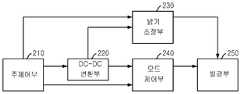
210 : 주제어부220 : DC-DC 변환부210: main controller 220: DC-DC converter
230 : 밝기 조정부240 : 모드 제어부230: brightness controller 240: mode controller
250 : 발광부250: light emitting unit
본 발명은 단말기의 발광 장치에 관한 것으로, 특히, 카메라 촬영 시 사용되는 플래쉬용 LED를 제어하는 단말기의 발광 장치에 관한 것이다.The present invention relates to a light emitting device of a terminal, and more particularly, to a light emitting device of a terminal for controlling a flash LED used when photographing a camera.
종래의 카메라 폰에서는 카메라 센서를 이용한 촬영 만이 가능했었으나, 그 이후, 외장형 스트로보를 이용한 플래쉬 기능을 사용하게 되었고, 현재는, 고휘도 LED를 단말기에 내장하고 이를 내장형 플래쉬로 사용하는 예가 늘고 있다.In the conventional camera phone, only shooting using a camera sensor was possible, but since then, a flash function using an external strobe has been used, and now, an example of using a high-brightness LED in a terminal and using it as a built-in flash has increased.
도 1은 종래의 내장형 플래쉬를 갖는 단말기를 나타낸 블록도로서, 이러한 종래의 단말기는, 플래쉬를 발광시키는 발광 인에이블 신호를 생성하는 주제어부(110); 주제어부(110)로부터 발광 인에이블 신호를 입력받으면 DC-DC 변환을 수행함으로써 발광부(140)에 발광용 전류를 공급하고, 주제어부(110)로부터 입력받은 밝기 조정 신호에 따라 조정 전류를 출력하는 DC-DC 변환부(120); DC-DC 변환부(120)의 조정 전류에 따라 발광부(140)의 밝기를 조정하는 밝기 조정부(130); 및 DC-DC 변환부(120)로부터 전류를 공급받아 밝기 조정부(130)에 의해 조정된 밝기로 발광하는 발광부(140)를 포함한다.1 is a block diagram showing a terminal having a conventional built-in flash, which includes a
그러나, 상술한 종래의 내장형 플래쉬를 갖는 단말기에 의하면, 단순히 발광부(140)를 소정의 밝기로 턴온/오프하는 기능만을 수행하므로, 촬영과 동시에 발광되어 실내에서 인물촬영을 할 경우 눈이 빨갛게 촬영되는 적목 현상이 발생하거나, 많이 어둡지 않은 곳에서 촬영할 경우 지나치게 발광 정도가 강하여 피사체가 하얗게 나오는 문제점이 있다.However, according to the terminal having the conventional built-in flash described above, since the
상기 문제점을 해결하기 위하여 안출된 본 발명은, 복수개의 플래쉬용 LED를 구비하고, 다양한 발광 모드를 제공함으로써 적목 현상 등을 방지하며, 이를 통하여 사용자의 다양한 욕구를 충족시켜 사용자 만족도를 높일 수 있는 단말기의 발광 장치를 제공하는 데 그 목적이 있다.
The present invention has been made to solve the above problems, and provided with a plurality of LED for flash, by providing a variety of light emission mode to prevent red-eye, etc. Through this terminal to satisfy the various needs of the user to increase the user satisfaction Its purpose is to provide a light emitting device.
상기 목적을 달성하기 위하여 본 발명의 단말기의 발광 장치는, 카메라모듈이 구비된 이동통신 단말기에 있어, 발광 모드[적목현상 방지모드, 최대 밝기모드, 특정세기 밝기모드, 특정LED모듈 발광모드]에 따라 제1발광제어신호, 제2발광제어신호 및 특정 크기의 밝기조절제어신호를 선택적으로 출력하는 주제어부; 다수의 LED가 각각 구비된 다수의 LED모듈로 이루어진 플래쉬; 상기 주제어부의 제어에 의해 활성화되어져, 상기 플래쉬에 적합한 발광전류 및 밝기조정전류를 변환, 공급하는 DC-DC 변환부; 상기 주제어부로부터 특정 크기의 밝기조절제어신호가 입력되면 상기 DC-DC 변환부로부터 입력되는 밝기조정전류를 해당 크기로 조정하여 상기 플래쉬로 전달하는 밝기 조정부; 및 상기 주제어부로부터 제1발광제어신호 및 제2발광제어신호가 교대로 입력되면 상기 DC-DC 변환부로부터 입력되는 발광전류를 상기 플래쉬의 각 LED모듈로 번갈아 가면서 전달하고, 상기 주제어부로부터 제1발광제어신호 및 제2발광제어신호가 모두 입력되면 상기 DC-DC 변환부로부터 입력되는 발광전류를 상기 플래쉬의 각 LED모듈로 동시에 전달하고, 상기 주제어부로부터 제1발광제어신호 및 제2발광제어신호 중 어느 하나의 신호가 입력되면 상기 DC-DC 변환부로부터 입력되는 발광전류를 상기 플래쉬의 특정 LED모듈로 전달하는 모드 제어부를 포함한다.In order to achieve the above object, the light emitting device of the terminal of the present invention, in a mobile communication terminal equipped with a camera module, in the light emitting mode (red-eye prevention mode, maximum brightness mode, specific intensity brightness mode, specific LED module light emitting mode] A main controller selectively outputting the first light emission control signal, the second light emission control signal, and a brightness control signal of a specific size; A flash consisting of a plurality of LED modules each having a plurality of LEDs; A DC-DC conversion unit activated by the control of the main controller to convert and supply a light emission current and a brightness adjustment current suitable for the flash; A brightness adjusting unit for adjusting a brightness adjusting current input from the DC-DC converter to a corresponding magnitude when the brightness adjusting control signal having a specific size is input from the main controller; And alternately transferring a first light emission control signal and a second light emission control signal from the main controller to alternately transmit light emission currents input from the DC-DC converter to each LED module of the flash. When both the first emission control signal and the second emission control signal are input, the emission current input from the DC-DC converter is simultaneously transmitted to each LED module of the flash, and the first emission control signal and the second emission from the main controller are simultaneously transmitted. And a mode controller for transmitting a light emission current input from the DC-DC converter to a specific LED module of the flash when one of the control signals is input.
이하, 본 발명이 속하는 기술분야에서 통상의 지식을 가진 자가 본 발명의 기술적 사상을 용이하게 실시할 수 있을 정도로 상세히 설명하기 위하여 본 발명의 가장 바람직한 실시예들을 첨부된 도면을 참조하여 설명하기로 한다.Hereinafter, the most preferred embodiments of the present invention will be described with reference to the accompanying drawings so that those skilled in the art can easily implement the technical idea of the present invention. .
먼저, 도 2는 본 발명의 일 실시예에 의한 단말기의 발광 장치를 나타낸 블록도로서, 이러한 본 발명의 단말기의 발광 장치는, 주제어부(210), DC-DC 변환부(220), 밝기 조정부(230), 모드 제어부(240) 및 발광부(250)를 포함한다.First, Figure 2 is a block diagram showing a light emitting device of the terminal according to an embodiment of the present invention, the light emitting device of the terminal of the present invention, the
주제어부(210)는, 플래쉬를 발광시키는 발광 인에이블 신호 및 플래쉬의 밝 기를 조절하는 밝기 조정 신호를 생성하고, 다양한 발광 모드를 제공하는 복수개의 모드 제어 신호를 생성하는 역할을 한다.The
또한, DC-DC 변환부(220)는, 상기 주제어부(210)로부터 입력받은 밝기 조정 신호에 따라 후술하는 발광부(250)에 조정 전류를 공급하고, 상기 주제어부(210)로부터 발광 인에이블 신호를 입력받으면 DC-DC 변환을 수행함으로써 후술하는 모드 제어부(240)에 발광용 전류를 공급하는 역할을 한다.In addition, the DC-
한편, 밝기 조정부(230)는, 상기 DC-DC 변환부(220)에서 입력된 조정 전류에 따라 후술하는 발광부(250)의 밝기를 조정하는 역할을 한다.The brightness adjusting
또한, 모드 제어부(240)는, 상기 주제어부(210)로부터 입력받은 상기 복수개의 모드 제어 신호를 통하여 스위칭 동작을 수행하고, 이를 통하여 상기 DC-DC 변환부(220)로부터 입력된 발광용 전류의 도통 시점 및 기간을 조절하는 역할을 한다.In addition, the
한편, 발광부(250)는, 복수개의 발광용 LED를 구비하고, 상기 모드 제어부(240)로부터 공급된 발광용 전류에 의하여 상기 밝기 조정부(230)에 의해 조정된 밝기로 발광하는 역할을 한다. 여기서, 상기 복수개의 발광용 LED 중 한 발광용 LED는 촬영 방향을 향하고, 상기 복수개의 발광용 LED 중 다른 한 발광용 LED는 촬영 방향에 비스듬한 방향을 향할 수 있다.The
도 3은 본 발명의 일 실시예에 의한 단말기의 발광 장치를 상세히 나타낸 예시도로서, 이에 관하여 설명하면 다음과 같다.3 is an exemplary view showing in detail a light emitting device of a terminal according to an embodiment of the present invention.
먼저, 상기 밝기 조정부(230) 내에 장착된 트랜지스터(231)는, 게이트 단자로 상기 주제어부(210)로부터의 밝기 조정 신호(밝기 조절)를 입력받고, 드레인 단자는 상기 발광부(250) 및 상기 DC-DC 변환부(220)에 연결되어, 상기 밝기 조정 신호에 따라 상기 DC-DC 변환부(220)에서 상기 발광부(250)로 흐르는 상기 조정 전류(FB)의 세기를 조정하는 역할을 한다.First, the
또한, 상기 밝기 조정부(230) 내에 장착된 제1 저항(232)은, 제1 단자가 상기 DC-DC 변환부(220)의 상기 조정 전류의 출력핀에 연결되고, 제2 단자가 접지되어 저항값을 제공하는 역할을 한다.In addition, the
한편, 상기 밝기 조정부(230) 내에 장착된 제2 저항(233)은, 제1 단자가 상기 트랜지스터(231)의 소스 단자에 연결되고, 제2 단자가 접지되어 저항값을 제공하는 역할을 한다.Meanwhile, the
또한, 상기 모드 제어부(240) 내에 장착된 논리 게이트(241)는, 상기 주제어부(210)로부터 상기 복수개의 모드 제어 신호(CTL1, CTL2)를 입력받고, 상기 복수개의 모드 제어 신호를 가지고 논리 연산을 수행하여 발광 모드 신호를 생성하는 역할을 한다. 여기서, 상기 논리 게이트(241)는 AND 게이트일 수 있으나 이에 한정되지 않는다.In addition, the
한편, 상기 모드 제어부(240) 내에 장착된 스위치(242)는, 상기 주제어부(210)로부터 상기 복수개의 모드 제어 신호를 입력받고, 상기 복수개의 모드 제어 신호에 따라 상기 DC-DC 변환부(220)로부터 입력된 상기 발광용 전류의 경로를 결정하는 역할을 한다.On the other hand, the
또한, 상기 모드 제어부(240) 내에 장착된 트랜지스터(243)는, 게이트 단자로 상기 발광 모드 신호를 입력받고, 소스 단자 및 드레인 단자가 상기 스위치(242)의 출력 경로에 각각 연결되어 상기 발광용 전류의 경로를 조정하는 역할을 한다.In addition, the
도 4a는 종래의 발광 동작을 나타낸 그래프이고, 도 4b는 본 발명의 일 실시예에 의한 단말기의 발광 장치의 동작을 나타낸 그래프로서, 이를 참조하여 본 발명의 단말기의 발광 장치의 동작에 관하여 설명하면 다음과 같다.4A is a graph illustrating a conventional light emitting operation, and FIG. 4B is a graph illustrating an operation of a light emitting device of a terminal according to an embodiment of the present invention. As follows.
먼저, 복수개의 모드 제어 신호(CTL1, CTL2)가 모두 제2 논리 단계(High)인 경우에는, 논리 게이트(241)에 의한 발광 모드 신호도 제2 논리 단계(High)가 되므로, 트랜지스터(243)가 턴온되어 발광용 전류가 발광부(250) 내 복수개의 발광용 LED에 모두 공급되어 최고 밝기의 발광 모드가 실현된다.First, when the plurality of mode control signals CTL1 and CTL2 are all in the second logic step High, since the light emission mode signal by the
한편, 복수개의 모드 제어 신호(CTL1, CTL2)가 번갈아 제2 논리 단계(High)로 되는 경우에는, 도 4b에 도시된 바와 같이, 발광용 전류가 발광부(250) 내 복수개의 발광용 LED에 번갈아 공급되고, 이를 통하여 복수개의 발광용 LED가 번갈아 켜지며 적목 감소 발광을 수행하게 된다. 이 때, 논리 게이트(241)에 의한 발광 모드 신호는 제1 논리 단계(Low)가 되어 트랜지스터(243)가 턴오프되고, 이에 따라 스위치(242)의 출력 경로가 서로 분리된다.On the other hand, when the plurality of mode control signals CTL1 and CTL2 alternately become the second logic step High, as shown in FIG. 4B, the light emitting current is applied to the plurality of light emitting LEDs in the
여기서, 복수개의 발광용 LED 중 하나는 정면을 향하게 하고, 하나는 정면에서 약간 빗겨가도록 각도를 잡으면 바운스 라이트(주변 배경에 반사되어 나오는 빛 을 이용하여 촬영하는 것으로 인물 사진에 사용하면 부드러운 톤의 사진을 얻을 수 있다)의 효과를 줄 수 있게 된다.Here, one of the plurality of light emitting LEDs is directed toward the front, and one is angled so as to be slightly deviated from the front, and the bounce light is taken by using light reflected from the surrounding background. Can be obtained).
이상에서 설명한 본 발명은, 본 발명이 속하는 기술분야에서 통상의 지식을 가진 자에 있어 본 발명의 기술적 사상을 벗어나지 않는 범위 내에서 여러 가지로 치환, 변형 및 변경이 가능하므로 전술한 실시예 및 첨부된 도면에 한정되는 것이 아니다.The present invention described above is capable of various substitutions, modifications, and changes without departing from the technical spirit of the present invention for those skilled in the art to which the present invention pertains. It is not limited to the drawings shown.
본 발명은 복수개의 플래쉬용 LED를 구비하고, 다양한 발광 모드를 제공함으로써 적목 현상 등을 방지하며, 이를 통하여 사용자의 다양한 욕구를 충족시켜 사용자 만족도를 높일 수 있는 장점이 있다.The present invention includes a plurality of LEDs for flash and prevents red-eye by providing various light emitting modes, thereby improving user satisfaction by satisfying various needs of the user.
Claims (6)
Translated fromKoreanPriority Applications (1)
| Application Number | Priority Date | Filing Date | Title |
|---|---|---|---|
| KR1020030084350AKR100559693B1 (en) | 2003-11-26 | 2003-11-26 | Light emitting device of the terminal |
Applications Claiming Priority (1)
| Application Number | Priority Date | Filing Date | Title |
|---|---|---|---|
| KR1020030084350AKR100559693B1 (en) | 2003-11-26 | 2003-11-26 | Light emitting device of the terminal |
Publications (2)
| Publication Number | Publication Date |
|---|---|
| KR20050050745A KR20050050745A (en) | 2005-06-01 |
| KR100559693B1true KR100559693B1 (en) | 2006-03-10 |
Family
ID=38666074
Family Applications (1)
| Application Number | Title | Priority Date | Filing Date |
|---|---|---|---|
| KR1020030084350AExpired - Fee RelatedKR100559693B1 (en) | 2003-11-26 | 2003-11-26 | Light emitting device of the terminal |
Country Status (1)
| Country | Link |
|---|---|
| KR (1) | KR100559693B1 (en) |
- 2003
- 2003-11-26KRKR1020030084350Apatent/KR100559693B1/ennot_activeExpired - Fee Related
Also Published As
| Publication number | Publication date |
|---|---|
| KR20050050745A (en) | 2005-06-01 |
Similar Documents
| Publication | Publication Date | Title |
|---|---|---|
| US7136672B2 (en) | Mobile telephone with built-in camera and flash | |
| US20100202779A1 (en) | IrDA transceiver module that also functions as remote control IR transmitter | |
| CN1643446A (en) | Portable devices and mobile phones with camera functions | |
| JP2006191559A (en) | Camera lens device for mobile terminals | |
| KR100593910B1 (en) | LED driving device for camera flash | |
| EP1318669A1 (en) | Image pick-up device and portable electronic device | |
| KR100559693B1 (en) | Light emitting device of the terminal | |
| US9048949B1 (en) | Controlling transmission power in an IrDA/RC transmitter circuit | |
| JP2010102208A (en) | Auxiliary light source device for photography | |
| US8229502B2 (en) | Mobile communications device, controller, and method for controlling a mobile communications device | |
| US20220187684A1 (en) | External light source for mobile devices | |
| CN113453408B (en) | A kind of supplementary light drive control circuit, method and network camera | |
| JP7118661B2 (en) | LENS DEVICE, IMAGING DEVICE, CONTROL METHOD AND PROGRAM | |
| KR100588190B1 (en) | Flash brightness control device in mobile communication terminal | |
| JP2004192001A (en) | Portable device with shooting function | |
| KR100713179B1 (en) | Light emitting device of camera module | |
| KR100464802B1 (en) | Circuit to emit light for stroboscope and flash | |
| KR200323618Y1 (en) | Emitting light apparatus for portable info-communications device using a high-brightness LED | |
| CN100539640C (en) | Mancarried device and mobile phone that camera function is arranged | |
| KR100642864B1 (en) | A user terminal equipped with a light emitting LED operation control function using an auto focus function and a control method thereof | |
| KR200408502Y1 (en) | Light emitting device of camera module | |
| JP2004185018A (en) | Portable device with shooting function | |
| KR20120053424A (en) | Image sensor and photographing apparatus having the same | |
| JP2019054008A (en) | Light emitting unit, light receiving unit, light emission control method, and program | |
| JP2007037163A (en) | Mobile phone |
Legal Events
| Date | Code | Title | Description |
|---|---|---|---|
| A201 | Request for examination | ||
| PA0109 | Patent application | St.27 status event code:A-0-1-A10-A12-nap-PA0109 | |
| PA0201 | Request for examination | St.27 status event code:A-1-2-D10-D11-exm-PA0201 | |
| R18-X000 | Changes to party contact information recorded | St.27 status event code:A-3-3-R10-R18-oth-X000 | |
| PN2301 | Change of applicant | St.27 status event code:A-3-3-R10-R13-asn-PN2301 St.27 status event code:A-3-3-R10-R11-asn-PN2301 | |
| PG1501 | Laying open of application | St.27 status event code:A-1-1-Q10-Q12-nap-PG1501 | |
| D13-X000 | Search requested | St.27 status event code:A-1-2-D10-D13-srh-X000 | |
| D14-X000 | Search report completed | St.27 status event code:A-1-2-D10-D14-srh-X000 | |
| E902 | Notification of reason for refusal | ||
| PE0902 | Notice of grounds for rejection | St.27 status event code:A-1-2-D10-D21-exm-PE0902 | |
| T11-X000 | Administrative time limit extension requested | St.27 status event code:U-3-3-T10-T11-oth-X000 | |
| T11-X000 | Administrative time limit extension requested | St.27 status event code:U-3-3-T10-T11-oth-X000 | |
| T11-X000 | Administrative time limit extension requested | St.27 status event code:U-3-3-T10-T11-oth-X000 | |
| E13-X000 | Pre-grant limitation requested | St.27 status event code:A-2-3-E10-E13-lim-X000 | |
| P11-X000 | Amendment of application requested | St.27 status event code:A-2-2-P10-P11-nap-X000 | |
| P13-X000 | Application amended | St.27 status event code:A-2-2-P10-P13-nap-X000 | |
| E701 | Decision to grant or registration of patent right | ||
| PE0701 | Decision of registration | St.27 status event code:A-1-2-D10-D22-exm-PE0701 | |
| GRNT | Written decision to grant | ||
| PR0701 | Registration of establishment | St.27 status event code:A-2-4-F10-F11-exm-PR0701 | |
| PR1002 | Payment of registration fee | St.27 status event code:A-2-2-U10-U11-oth-PR1002 Fee payment year number:1 | |
| PG1601 | Publication of registration | St.27 status event code:A-4-4-Q10-Q13-nap-PG1601 | |
| R18-X000 | Changes to party contact information recorded | St.27 status event code:A-5-5-R10-R18-oth-X000 | |
| PR1001 | Payment of annual fee | St.27 status event code:A-4-4-U10-U11-oth-PR1001 Fee payment year number:4 | |
| PR1001 | Payment of annual fee | St.27 status event code:A-4-4-U10-U11-oth-PR1001 Fee payment year number:5 | |
| PR1001 | Payment of annual fee | St.27 status event code:A-4-4-U10-U11-oth-PR1001 Fee payment year number:6 | |
| PR1001 | Payment of annual fee | St.27 status event code:A-4-4-U10-U11-oth-PR1001 Fee payment year number:7 | |
| FPAY | Annual fee payment | Payment date:20130304 Year of fee payment:8 | |
| PR1001 | Payment of annual fee | St.27 status event code:A-4-4-U10-U11-oth-PR1001 Fee payment year number:8 | |
| FPAY | Annual fee payment | Payment date:20140228 Year of fee payment:9 | |
| PR1001 | Payment of annual fee | St.27 status event code:A-4-4-U10-U11-oth-PR1001 Fee payment year number:9 | |
| FPAY | Annual fee payment | Payment date:20150302 Year of fee payment:10 | |
| PR1001 | Payment of annual fee | St.27 status event code:A-4-4-U10-U11-oth-PR1001 Fee payment year number:10 | |
| FPAY | Annual fee payment | Payment date:20160302 Year of fee payment:11 | |
| PR1001 | Payment of annual fee | St.27 status event code:A-4-4-U10-U11-oth-PR1001 Fee payment year number:11 | |
| PN2301 | Change of applicant | St.27 status event code:A-5-5-R10-R11-asn-PN2301 | |
| PN2301 | Change of applicant | St.27 status event code:A-5-5-R10-R14-asn-PN2301 | |
| PN2301 | Change of applicant | St.27 status event code:A-5-5-R10-R11-asn-PN2301 | |
| PN2301 | Change of applicant | St.27 status event code:A-5-5-R10-R14-asn-PN2301 | |
| LAPS | Lapse due to unpaid annual fee | ||
| PC1903 | Unpaid annual fee | St.27 status event code:A-4-4-U10-U13-oth-PC1903 Not in force date:20170304 Payment event data comment text:Termination Category : DEFAULT_OF_REGISTRATION_FEE | |
| R18-X000 | Changes to party contact information recorded | St.27 status event code:A-5-5-R10-R18-oth-X000 | |
| PC1903 | Unpaid annual fee | St.27 status event code:N-4-6-H10-H13-oth-PC1903 Ip right cessation event data comment text:Termination Category : DEFAULT_OF_REGISTRATION_FEE Not in force date:20170304 | |
| P22-X000 | Classification modified | St.27 status event code:A-4-4-P10-P22-nap-X000 |