KR100557040B1 - Optical pickup system - Google Patents
Optical pickup systemDownload PDFInfo
- Publication number
- KR100557040B1 KR100557040B1KR1020030100440AKR20030100440AKR100557040B1KR 100557040 B1KR100557040 B1KR 100557040B1KR 1020030100440 AKR1020030100440 AKR 1020030100440AKR 20030100440 AKR20030100440 AKR 20030100440AKR 100557040 B1KR100557040 B1KR 100557040B1
- Authority
- KR
- South Korea
- Prior art keywords
- spherical aberration
- lens holder
- shaft
- lens
- optical
- Prior art date
- Legal status (The legal status is an assumption and is not a legal conclusion. Google has not performed a legal analysis and makes no representation as to the accuracy of the status listed.)
- Expired - Fee Related
Links
Images


Classifications
- G—PHYSICS
- G11—INFORMATION STORAGE
- G11B—INFORMATION STORAGE BASED ON RELATIVE MOVEMENT BETWEEN RECORD CARRIER AND TRANSDUCER
- G11B7/00—Recording or reproducing by optical means, e.g. recording using a thermal beam of optical radiation by modifying optical properties or the physical structure, reproducing using an optical beam at lower power by sensing optical properties; Record carriers therefor
- G11B7/08—Disposition or mounting of heads or light sources relatively to record carriers
- G11B7/085—Disposition or mounting of heads or light sources relatively to record carriers with provision for moving the light beam into, or out of, its operative position or across tracks, otherwise than during the transducing operation, e.g. for adjustment or preliminary positioning or track change or selection
- G—PHYSICS
- G11—INFORMATION STORAGE
- G11B—INFORMATION STORAGE BASED ON RELATIVE MOVEMENT BETWEEN RECORD CARRIER AND TRANSDUCER
- G11B7/00—Recording or reproducing by optical means, e.g. recording using a thermal beam of optical radiation by modifying optical properties or the physical structure, reproducing using an optical beam at lower power by sensing optical properties; Record carriers therefor
- G11B7/12—Heads, e.g. forming of the optical beam spot or modulation of the optical beam
- G11B7/135—Means for guiding the beam from the source to the record carrier or from the record carrier to the detector
- G11B7/1372—Lenses
- G11B7/1378—Separate aberration correction lenses; Cylindrical lenses to generate astigmatism; Beam expanders
- G—PHYSICS
- G11—INFORMATION STORAGE
- G11B—INFORMATION STORAGE BASED ON RELATIVE MOVEMENT BETWEEN RECORD CARRIER AND TRANSDUCER
- G11B7/00—Recording or reproducing by optical means, e.g. recording using a thermal beam of optical radiation by modifying optical properties or the physical structure, reproducing using an optical beam at lower power by sensing optical properties; Record carriers therefor
- G11B7/08—Disposition or mounting of heads or light sources relatively to record carriers
- G11B7/09—Disposition or mounting of heads or light sources relatively to record carriers with provision for moving the light beam or focus plane for the purpose of maintaining alignment of the light beam relative to the record carrier during transducing operation, e.g. to compensate for surface irregularities of the latter or for track following
- G11B7/0925—Electromechanical actuators for lens positioning
- G—PHYSICS
- G11—INFORMATION STORAGE
- G11B—INFORMATION STORAGE BASED ON RELATIVE MOVEMENT BETWEEN RECORD CARRIER AND TRANSDUCER
- G11B7/00—Recording or reproducing by optical means, e.g. recording using a thermal beam of optical radiation by modifying optical properties or the physical structure, reproducing using an optical beam at lower power by sensing optical properties; Record carriers therefor
- G11B7/12—Heads, e.g. forming of the optical beam spot or modulation of the optical beam
- G11B7/135—Means for guiding the beam from the source to the record carrier or from the record carrier to the detector
- G11B7/1392—Means for controlling the beam wavefront, e.g. for correction of aberration
- G11B7/13925—Means for controlling the beam wavefront, e.g. for correction of aberration active, e.g. controlled by electrical or mechanical means
- G11B7/13927—Means for controlling the beam wavefront, e.g. for correction of aberration active, e.g. controlled by electrical or mechanical means during transducing, e.g. to correct for variation of the spherical aberration due to disc tilt or irregularities in the cover layer thickness
Landscapes
- Physics & Mathematics (AREA)
- Optics & Photonics (AREA)
- Optical Head (AREA)
- Optical Recording Or Reproduction (AREA)
- Optical Radar Systems And Details Thereof (AREA)
- Mechanical Optical Scanning Systems (AREA)
Abstract
Description
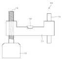
Translated fromKorean도 1은 종래 BD급 광 픽업장치를 나타낸 구성도.1 is a block diagram showing a conventional BD-class optical pickup device.
도 2는 종래 도 1에 적용된 구면수차 보상용 액츄에이터의 구조.Figure 2 is a structure of the spherical aberration compensation actuator conventionally applied to Figure 1;
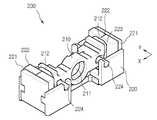
도 3은 본 발명 실시 예에 따른 BD급 광 픽업장치에 있어서, 구면수차 보상용 액츄에이터의 구조를 나타낸 사시도.Figure 3 is a perspective view showing the structure of the spherical aberration compensation actuator in the BD optical pickup apparatus according to an embodiment of the present invention.
도 4는 도 3의 분해 사시도.4 is an exploded perspective view of FIG. 3.
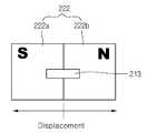
도 5는 본 발명에 따른 구면수차보상용 액츄에이터에서의 자기회로 구성도.5 is a magnetic circuit diagram of the spherical aberration compensation actuator according to the present invention.
도 6은 본 발명에 따른 자기 스프링에 의한 자기 복원력을 나타내기 위한 도면.Figure 6 is a view for showing the self restoring force by the magnetic spring according to the present invention.
도 7은 본 발명 실시 예에 따른 렌즈홀더 이동에 따른 자기복원력을 나타낸 그래프.7 is a graph showing the self-resilience according to the movement of the lens holder according to an embodiment of the present invention.
도 8의 (a)(b)는 본 발명에 따른 렌즈홀더 샤프트 가이드부의 형상의 다른 예를 나타낸 도면.Figure 8 (a) (b) is a view showing another example of the shape of the lens holder shaft guide portion according to the present invention.
도 9는 본 발명 실시 예에 따른 샤프트 가이드홈의 구조를 나타낸 도면.9 is a view showing the structure of the shaft guide groove according to the embodiment of the present invention.
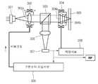
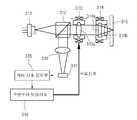
도 10은 도 3의 구면수차 보상용 액츄에이터를 구비한 광 픽업 장치에 있어서, 집광부 지터 신호를 이용하여 서보하기 위한 광 픽업 시스템 구성도.10 is an optical pickup system including the spherical aberration compensating actuator of FIG. 3, wherein the optical pickup system is configured to servo using a light collecting unit jitter signal.
도 11은 도 3의 구면수차 보상용 액츄에이터를 구비한 광 픽업 장치에 있어 서, 집광부 지터 신호를 이용하여 서보하기 위한 광 픽업 시스템 구성도.11 is an optical pickup system including the spherical aberration compensating actuator of FIG. 3, wherein the optical pickup system is configured to servo using a light collecting unit jitter signal.
<도면의 주요부분에 대한 부호의 설명><Description of the symbols for the main parts of the drawings>
200,302,313...구면수차 보상 액츄에이터Spherical Aberration Compensation Actuator
210...렌즈홀더211,302a,313a...콜리메이터 렌즈210.Lens holder 211,302a, 313a ... Collector lens
212...코일213...자성철편212
220...베이스221...요크220 ...
222...마그네트223...샤프트 가이드홈222 ...
224...샤프트225...샤프트 고정홈224
225a...고정돌기226...요크 고정돌기225a ...
본 발명은 광 픽업장치에 있어서, 특히 구면수차 보상을 위해 광 경로 상에 1축 방향으로 가동하여 광 경로를 변환시켜 주는 구면수차 보상디바이스를 갖는 광 픽업 장치에 관한 것이다.BACKGROUND OF THE INVENTION 1. Field of the Invention The present invention relates to an optical pickup apparatus, in particular, having an spherical aberration compensation device for shifting the optical path by uniaxially moving on the optical path for spherical aberration compensation.
광 저장장치의 배속 및 저장 밀도 증가와 함께 소비자 기호의 고급화로 고화질 동영상 처리에 대한 수요가 증가함에 따라 광 저장 디스크(Optical Disk)의 데이터 저장용량도 대용량으로 요구되고 있다.As the demand for high-definition video processing increases due to the increase in the speed and storage density of optical storage devices and the advancement of consumer preferences, the data storage capacity of optical disks is also required as a large capacity.
이러한 요구로서, 블루 레이저 다이오드(BD: Blue laser Diode)급 광학 시스 템이 제시되고 있다. 이러한 브루 레이저급 광학 시스템에서는 고 개구수(예컨대, NA=0.85), 짧은 파장(예컨대, 405nm)의 레이저 광을 사용한다.As such a demand, a blue laser diode (BD) class optical system has been proposed. This brew laser class optical system uses laser light of high numerical aperture (eg NA = 0.85) and short wavelength (eg 405 nm).
도 1은 블루 레이저급 광 픽업 시스템의 개략 구성도이다.1 is a schematic configuration diagram of a blue laser class optical pickup system.
도 1을 참조하면, 블루 레이저(Blue Laser) 빔을 발생하는 블루 레이저 다이오드(101)와, 빔을 반사 또는 투과시키는 빔 스플리터(102)와, 상기 빔 스플리터(102)로부터 입사된 빔을 평행화된 빔으로 출사하는 콜리메이터 렌즈(103)와, 상기 콜리메이터 렌즈(103)로부터 입사된 빔을 광 디스크(105)에 집광시키고 반사되는 빔을 상기 콜레메이터 렌즈(103)로 전달하는 대물렌즈(104)와, 상기 빔 스플리터(102)에 의해 반사된 빔을 전기적 신호로 검출하는 광 검출기(106)로 구성된다.Referring to FIG. 1, a
상기와 같이 구성되는 블루 레이저급 광 픽업 시스템은 도 1에 도시된 바와 같다.The blue laser optical pickup system configured as described above is as shown in FIG.
도 1에 도시된 바와 같이, 블루 레이저 다이오드(BD)(101)로부터 발생되는 레이저 빔은 빔 스플리터(102)를 투과하고, 투과된 빔은 콜리메이터 렌즈(103)에서 평행 빔으로 대물렌즈(104)에 입사된다. 대물렌즈(104)는 입사된 빔을 광 디스크(105) 상에 한 점으로 집광시켜 정보를 기록 및 재생하게 되며, 광 디스크(105)로부터 맺힌 빔은 반사되고, 반사된 빔은 대물렌즈(104), 콜리메이터 렌즈(103)를 투과하여 빔 스플리터(102)에 의해 광 검출기(106)로 반사된다. 광 검출기(106)는 반사되어 입력되는 정보를 전기적인 신호로 변환하게 된다.As shown in FIG. 1, a laser beam generated from a blue laser diode (BD) 101 passes through a
여기서, 블루 레이저급 광학 시스템은 데이터의 고집적화 및 대용량화를 위 해 디스크에 두 개의 레이어(layer)가 존재하며, 사용되고 있는 광원의 파장이 짧아 디스크 커버 레이어의 편차에 의한 구면수차 발생이 광학수차 허용치를 벗어나거나, 저장밀도 증가를 위해 듀얼 레이어 디스크를 사용하면서 각 레이어의 편차에 의해 구면수차가 발생하게 된다. 특히, 듀얼 레이어 디스크(Dual layer disk)의 기록/재생으로 각각의 디스크 레이어의 편차에 의한 구면수차를 보상하기 위해서는 광 경로상에 광학 소자를 오프셋(offset) 시켜 주어야한다.Here, in the blue laser class optical system, two layers exist on the disk for high data integration and large capacity, and the spherical aberration caused by the deviation of the disk cover layer is reduced due to the short wavelength of the light source being used. Spherical aberration occurs due to the deviation of each layer while using the dual-layer disc to increase or increase the storage density. In particular, in order to compensate for spherical aberration caused by the deviation of each disk layer by recording / reproducing the dual layer disk, it is necessary to offset the optical element on the optical path.
이러한 구면수차를 보상해주기 위해 광 축상의 광학소자를 이동시켜 주어야 하는 1축 구동 서보 시스템이 요구된다.In order to compensate for this spherical aberration, there is a need for a single-axis drive servo system that must move an optical element on an optical axis.
기존의 구면 수차 보상을 위한 1축 액츄에이터는 도 2에 도시된 바와 같이, 구면수차 보상을 위한 액츄에이터(110)의 경우, 렌즈홀더(111)의 중심부에 콜리메이터 렌즈(112)를 취부하고, 렌즈홀더(111)의 가동을 위한 모터(113), 렌즈홀더(111)의 일측에서 상기 모터(113)에 의해 회전하여 렌즈홀더(111)를 가동하는 리드 스크류(lead screw)(114), 렌즈홀더(111)의 타측에서 렌즈홀더의 이동을 가이드하는 샤프트(115)로 구성된다.In the conventional single axis actuator for spherical aberration compensation, as shown in FIG. 2, in the case of the
즉, 콜리메이터 렌즈(112)에 의한 구면수차를 보상하기 위해서는 렌즈홀더(111)를 광 축 방향으로 이동시켜 주어야 하는데, 이때 모터(113)를 구동하면 모터 축에 연결된 리드 스크류(114)가 회전하여 렌즈홀더(111)를 전/후 방향으로 이동시켜 준다. 더블어 렌즈홀더 타측의 샤프트(115)가 렌즈홀더의 이동을 가이드해 주게 됨으로써, 구면수차를 보상하게 된다.That is, in order to compensate for spherical aberration caused by the
그러나, 모터(113)의 축인 리드 스크류(114)가 렌즈홀더 일측에 설치되어 있 기 때문에, 렌즈홀더를 가동하는 힘이 한쪽으로 집중되는 경우가 발생될 수 있다. 또한, 리드 스크류 방식을 이용하게 될 경우 별도의 모터-스크류 시스템을 구성해야 하는 등 가격 및 조립성 측면에서 단점을 가지게 된다.However, since the
그리고, 구면 수차를 최소화할 수 있는 1축 액츄에이터는 그 특성상 고정밀도의 구동이 요구되므로, 수십 um이하의 구동 정밀도와 광학소자의 틸트 마진을 확보하기 위해 구동 중 각도 틀어짐이 최소화되어야 한다. 또한 별도의 서보계를 구성하는 경우 실시간으로 위치 정보에 대한 피드백이 필요하므로, 회로 시스템의 추가 구성이 필요하게 된다.In addition, since a single-axis actuator capable of minimizing spherical aberration requires high precision driving, the angular shift during driving should be minimized to secure driving precision of several tens of um or less and tilt margin of the optical device. In addition, when configuring a separate servo system, since feedback on the position information is required in real time, an additional configuration of a circuit system is required.
본 발명은 상기한 문제를 해결하기 위해 안출된 것으로서, BD급 광 픽업 시스템에서의 디스크 커버 레이어 편차로 인해 발생할 수 있는 구면수차를 보상하기 위해 광축상에 전 자기력으로 가동하는 액츄에이터를 배치하고, 콜리메이터 렌즈를 광 축방향을 따라 이동시켜 줄 수 있도록 한 광 픽업 시스템을 제공함에 그 목적이 있다.SUMMARY OF THE INVENTION The present invention has been made to solve the above-mentioned problem, and arranges an actuator which operates with an electromagnetic force on an optical axis to compensate for spherical aberration which may occur due to disc cover layer deviation in a BD-class optical pickup system. It is an object of the present invention to provide an optical pickup system capable of moving a lens along an optical axis direction.
본 발명의 다른 목적은 구면수차 보상 액츄에이터의 렌즈홀더에 콜리메이터 렌즈를 취부하고, 그 좌/우측에 광 축 방향으로의 가동력을 발생하는 자기회로 및 광 축 방향으로의 가동을 가이드하는 가이드수단을 더 구비하여, 고가의 모터를 사용하지 않고 간단하게 구성할 수 있도록 한 광 픽업 시스템을 제공함에 그 목적이 있다.Another object of the present invention is to provide a collimator lens to the lens holder of the spherical aberration compensation actuator, and to guide the movement in the optical axis direction and the magnetic circuit for generating the movable force in the optical axis direction on the left and right sides thereof. It is an object of the present invention to provide an optical pickup system that can be easily configured without using an expensive motor.
본 발명의 또 다른 목적은 렌즈홀더의 가동을 위한 자기회로로서 코일 및 마그네트를 구비하고, 상기 마그네트의 극성 경계에 위치하고 대향하는 위치에 자기 복원력을 위한 자성철편을 포함하여, 감도 및 해상도를 변화시킬 수 있도록 한 광 픽업 시스템을 제공함에 그 목적이 있다.It is still another object of the present invention to provide a magnetic circuit for driving a lens holder, including a coil and a magnet, and to include a magnetic iron piece for magnetic resilience at an opposite position located at a polar boundary of the magnet, thereby changing sensitivity and resolution. It is an object of the present invention to provide an optical pickup system.
본 발명의 또 다른 목적은 샤프트 및 샤프트 가이드홈으로 회동 가이드수단을 구성하되, 샤프트 가이드홈이 적어도 하나는 2방향 가이드를 수행하고, 나머지 하나는 4방향 가이드를 수행할 수 있도록 한 광 픽업 시스템을 제공함에 그 목적이 있다.
Another object of the present invention comprises an optical pickup system constituting a rotation guide means with a shaft and a shaft guide groove, the shaft guide groove is at least one to perform a two-way guide, the other to perform a four-way guide The purpose is to provide.
상기한 목적 달성을 위한 본 발명에 따른 광 픽업 시스템은,Optical pickup system according to the present invention for achieving the above object,
레이저 빔을 발생하는 레이저 다이오드와;A laser diode for generating a laser beam;
입사된 빔이 평행하게 진행하도록 하는 콜리메이터 렌즈를 취부하고, 코일 및 마그네트 사이에 발생되는 전 자기력으로 인해 광 축 방향으로 가동하는 구면수차 보상 액츄에이터와;A spherical aberration compensation actuator for attaching a collimator lens for allowing the incident beam to run in parallel, and moving in an optical axis direction due to an electromagnetic force generated between the coil and the magnet;
입사된 빔의 편광 방향에 따라 선택적으로 빔이 투과되거나 반사되도록 하는 빔 스플리터와;A beam splitter for selectively transmitting or reflecting the beam according to the polarization direction of the incident beam;
상기 투과된 빔을 광 디스크 상의 한 점에 집광시키는 대물렌즈와;An objective lens for condensing the transmitted beam at a point on an optical disk;
상기 디스크로부터 반사된 빔을 전기적인 신호로 검출하는 광 검출기를 포함하는 것을 특징으로 한다.And a photo detector for detecting the beam reflected from the disk as an electrical signal.
바람직하게, 상기 구면수차 보상 액츄에이터는 콜리메이터 렌즈를 취부하고 가동하는 렌즈홀더와; 상기 렌즈홀더의 좌/우측에 배치되어 전자기력에 의해 상기 렌즈홀더를 가동시키는 자기회로와; 상기 렌즈홀더의 가동을 가이드하는 가동 가이드 수단과; 상기 렌즈홀더의 가동을 지지하기 위한 베이스를 포함하는 것을 특징으로 한다.Preferably, the spherical aberration compensation actuator comprises: a lens holder for mounting and operating a collimator lens; Magnetic circuits disposed at left and right sides of the lens holder to move the lens holder by electromagnetic force; Movable guide means for guiding the movement of the lens holder; It characterized in that it comprises a base for supporting the operation of the lens holder.
바람직하게, 상기 자기회로는, 렌즈홀더의 좌/우면에 부착된 코일과, 상기 코일과 대향하는 2극성 마그네트와, 상기 마그네트가 내측면에 안착되는 U자형 요크를 포함하는 것을 특징으로 한다.Preferably, the magnetic circuit includes a coil attached to the left and right surfaces of the lens holder, a bipolar magnet facing the coil, and a U-shaped yoke on which the magnet is seated on an inner surface thereof.
바람직하게, 상기 렌즈홀더의 좌/우측면에 자기 복원력을 위한 자성철편이 상기 마그네트의 극성 경계에 위치한 것을 특징으로 한다.Preferably, the magnetic iron piece for the magnetic restoring force on the left / right side of the lens holder is located on the polar boundary of the magnet.
바람직하게, 상기 회동 가이드수단은 렌즈홀더의 좌/우측에 렌즈 높이 방향 중심 및 렌즈 기준 대칭이 되도록 형성되는 샤프트 가이드홈 및 샤프트와, 상기 샤프트의 양단을 지지 및 고정하기 위해 베이스에 형성된 샤프트 고정홈을 포함하는 것을 특징으로 한다.Preferably, the rotation guide means includes a shaft guide groove and a shaft formed at the center of the lens height direction and the lens reference symmetry at left and right sides of the lens holder, and a shaft fixing groove formed at the base to support and fix both ends of the shaft. Characterized in that it comprises a.
바람직하게, 상기 샤프트 가이드홈은 렌즈홀더 일측에 사각형상으로 형성되어 렌즈홀더를 상하/좌우 방향으로 가이드하고, 렌즈홀더 타측에 장공으로 처리되어 렌즈홀더를 좌/우 방향으로 가이드하는 것을 특징으로 한다.Preferably, the shaft guide groove is formed in a rectangular shape on one side of the lens holder to guide the lens holder in the up and down / left and right direction, the lens holder is treated as a long hole to guide the lens holder in the left / right direction .
바람직하게, 상기 샤프트 고정홈은 베이스의 양측면에 평행한 샤프트와 동일 선상에 형성되며, 일측 내면에 내향되는 돌기를 형성하여 샤프트가 끼워 고정될 수 있도록 한 것을 특징으로 한다.Preferably, the shaft fixing groove is formed on the same line as the shaft parallel to both sides of the base, it characterized in that the projection formed inwardly on one inner surface so that the shaft can be fitted and fixed.
바람직하게, 상기 광 검출기에 의해 검출되는 지터 신호에 따라 상기 구면수차 보상 액츄에이터의 구면수차 보상 서보의 가동을 제어하는 구면수차 보상 서보를 더 포함하는 것을 특징으로 한다.The spherical aberration compensation servo may be further configured to control the operation of the spherical aberration compensation servo of the spherical aberration compensation actuator according to the jitter signal detected by the photo detector.
바람직하게, 상기 구면수차 보상 액츄에이터는 빔 스플리터의 전단 또는 후단에 배치되는 것을 특징으로 한다.Preferably, the spherical aberration compensating actuator is disposed at the front or rear end of the beam splitter.
이하 첨부된 도면을 참조하여 설명하면 다음과 같다.Hereinafter, with reference to the accompanying drawings as follows.
도 3은 본 발명에 따른 구면수차 보상 액츄에이터의 사시도이고, 도 4는 도 3의 분해 사시도이다.3 is a perspective view of a spherical aberration compensation actuator according to the present invention, and FIG. 4 is an exploded perspective view of FIG. 3.
도 3 및 도 4를 참조하면, 빔을 평행하게 진행시키는 콜리메이터 렌즈(211)가 취부되며 광 축 방향으로 가동하는 렌즈홀더(210)와; 상기 렌즈홀더(210)의 좌/우측에 구비된 코일(212) 및 마그네트(222), 요크(221)와, 상기 렌즈홀더(210)의 광 축 방향으로의 가동을 가이드하는 샤프트 가이드홈(223) 및 샤프트(224)와, 상기 샤프트(224)의 양단을 지지하는 베이스(220)를 포함하는 구성이다.3 and 4, a
도 5를 참조하면, 상기 렌즈홀더(210)의 양측면에는 코일(212) 및 자성철편(213)이 마그네트(222)의 극성(S:N) 경계에 고정된 것을 특징으로 한다.Referring to FIG. 5, the
도 4에 도시된 상기 베이스(220)에는 양측으로 샤프트(222)와 동일 선상에서 형성된 샤프트 고정홈(225) 및 샤프트 고정홈(225)의 입구측에 내향된 돌기(도 9 참조, 225a)를 더 포함하는 구성이다.The base 220 shown in FIG. 4 has a
상기와 같이 구성되는 본 발명 실시 예에 따른 블루 레이저급 광학 시스템에 대하여 첨부된 도면을 참조하여 설명하면 다음과 같다.Referring to the accompanying drawings, the blue laser optical system according to an embodiment of the present invention configured as described above is as follows.
먼저, 블루 레이저급 광학 시스템은 사용 광원의 파장이 짧아 디스크 커버 레이어의 편차에 의해 구면 수차 허용치가 벗어나거나, 저장밀도 증가를 위해 듀얼 레이어 디스크를 사용하면서 각 레이어의 편차에 의해 구면수차가 발생하게 된다. 이러한 구면수차를 보상해주기 위해 광 축상의 광학소자를 이동시켜 주어야 하는 1축 구동 서보 시스템이 요구된다.First, the blue laser optical system has a short wavelength of the light source so that the spherical aberration is out of tolerance due to the disc cover layer deviation, or the spherical aberration is caused by the deviation of each layer while using the dual layer disc to increase the storage density. do. In order to compensate for this spherical aberration, there is a need for a single-axis drive servo system that must move an optical element on an optical axis.
이를 위해, 도 3 및 도 4에 도시된 바와 같이, 광 축상에 설치되는 구면수차 보상 액츄에이터(200)는 1축 액츄에이터로서 광 축 방향으로 직선운동을 하게 되며, 이를 위해 렌즈홀더(210) 및 자기회로, 샤프트(224), 베이스(220)를 포함한다.3 and 4, the spherical
상기 렌즈홀더(210)는 중심부의 형성된 빔 통과공(210a)으로 콜리메이터 렌즈(211)가 안착되며, 좌/우측으로 렌즈홀더(210)의 가동을 위한 자기회로를 구비하고, 가동을 가이드하는 샤프트(224)가 축 방향으로 설치된다.The
여기서, 샤프트(224)는 렌즈홀더(210)의 광 축 방향의 움직임을 가이드하기 위해 두 개의 샤프트(224)를 렌즈 높이 방향 중심 및 렌즈 기준 대칭이 되도록 좌우에 배치하게 된다.Here, the
그리고, 자기회로는 코일(212) 및 마그네트(222), 요크(221)로 구성되며, 렌즈홀더(210)를 가동하는 구동력을 발생한다. 이를 위해, 상기 렌즈홀더(210)의 좌/우측면에 코일(212)이 부착되며, 이에 대향하는 위치에 마그네트(222)가 요크(221) 내면에 부착, 고정된다.The magnetic circuit includes a
여기서, 상기 마그네트(222)는 축 방향으로 2극(S:N)이 설치되는데, 단극성 2개로 하거나 단일개의 2극성 마그네트를 설치할 수도 있다. 그리고, 마그네트(222)의 극성 경계면에 코일(221) 중심이 대향되게 설치된다. 이러한 코일(212) 및 마그네트(222)는 상호간에 발생되는 힘은 로렌츠 힘의 방향을 광 축 방향으로 하여 콜리메이터 렌즈(211)를 구동하게 된다.Here, the
그리고, 요크(221)는 자속의 극대화를 위해 U자형으로 설치하며 양측 마그네트(222)가 직립된 요크 내측면으로 부착된다.In addition, the
그리고, 베이스(220)는 전체 액츄에이터를 지지 및 고정시켜 주기 위해, 샤프트(224) 및 요크(221)를 지지한다. 이를 위해, 베이스 후면에 요크 고정돌기(226)를 내측으로 돌출시켜 요크의 배면에 형성된 고정홈(221a)이 끼워지도록 하며, 또 내부에 요크 유동 방지부(227)를 형성하여 내부로 끼워지는 요크(221)의 상/하 유동을 방지하게 된다.In addition, the
이러한 렌즈홀더(210)의 가동을 가이드하기 위한 상기 샤프트(224)는 그 중심부가 렌즈홀더(210)의 좌/우측에 축 방향으로 형성된 샤프트 가이드홈(223)에 삽입되고, 샤프트(224)의 양단은 베이스(220)의 전/후 측면에 형성된 샤프트 고정홈(225)으로 안착되므로, 상기 렌즈홀더(210)가 자기회로에 의해 가동될 때, 샤프트(224)를 따라 전/후 방향(광 축 방향)으로 이동된다.The
이의 동작을 설명하면, 구면수차 보상 액츄에이터(200)는 광 축 상에서 콜리메이터 렌즈(211)를 취부하고 광 축 방향으로 이동하게 되므로 구면수차 보상 또는 광로변환 액츄에이터로 기능하게 된다.Referring to this operation, the spherical
이러한 액츄에이터(200)의 코일(212)에 전류가 인가되면 코일(212)과 이에 대향하는 마그네트(222) 사이에 전자기력이 발생되고, 발생되는 전자기력은 코일(212) 및 렌즈홀더(210)를 축 방향으로 이동시켜 준다. 이때 렌즈홀더(210)는 샤프트(224) 및 샤프트 가이드홈(223)을 따라 이동하게 된다. 이때 코일(212)에 인가되는 전류의 방향에 따라 전 방향 또는 후 방향으로 이동하게 된다.When a current is applied to the
또한, 도 5 및 도 6에 도시된 바와 같이, 렌즈홀더(210)의 양측면 중심 위치에 자성철편(213)이 각각 안착된다. 이러한 자성철편(213)은 렌즈홀더(210)의 양측 면에 형성된 탄성 스프링으로서, "ㄷ"자형 철편 고정홈(214)에 각각 안착되며 마그네트(222)의 극성 경계면에 위치한다.In addition, as shown in FIGS. 5 and 6, the
이에 따라 상기 자성철편(213)은 별도의 조립 지그없이 철편 고정홈(214)에 삽입후 접착만으로 고정이 가능하게 된다. 또 철편 고정홈(214)을 소정 깊이로 하여, 자기 스프링의 강성 값을 조절할 때 렌즈홀더(210)의 수정 없이도 자성철편(213)의 두께만으로 변화시킬 수 있다. 도 7에 도시된 바와 같이, 상기 자성철편(213) 및 마그네트(222)의 상호 작용에 의한 이동 거리 대비 힘의 상호 관계를 그래프로 나타낼 수 있다.Accordingly, the
또한 상기 자성철편(213)은 도 6과 같이, 렌즈홀더(210)의 좌/우측에 고정된 마그네트(222)의 극성 경계(S:N)에 위치하게 된다. 이는 자석의 극 사이에 가장 높은 자기 밀도가 형성되어 자성철편(213)이 극성 사이에 위치하고자 하는 잠재 에너지의 안정점 특성(stable point of potential energy, 자기 스프링)에 의한 것으로, 자성철편(213)이 극성 사이에서 벗어나게 되면 다시 원 상태로 돌아가려하는 복원력이 발생하게 된다.Also, as shown in FIG. 6, the
따라서, 코일(212)과 마그네트(222)에 의해 발생되는 전자기력과 자기 복원 력 간의 차이에 의해 렌즈홀더(210)는 특정 지점에서 고정될 수 있다. 즉, 자성철편(213)의 두께 및 사이즈, 마그네트(222)와의 거리만을 조정하면 감도 및 해상도를 변화시킬 수 있다.Therefore, the
한편, 도 4에 도시된 바와 같이, 렌즈홀더(210)의 좌/우에서 샤프트(224)를 가이드하는 샤프트 가이드홈(223: 223a,223b)은 서로 다른 형상으로 형성된다. 즉, 렌즈홀더(210)의 일측 가이드홈(223a)은 원형으로 하여 상하/좌우의 두 방향 가이드가 가능하며, 타측 가이드홈(223b)은 사각형으로 처리하여 상하 방향으로 가이드하게 함으로써, 구동 중 발생할 수 있는 렌즈홀더(210)의 틸트로 인해 샤프트(224)와 렌즈홀더(210) 사이의 마찰력 상승시에도 구동이 자유롭도록 자유도를 해제하였다.On the other hand, as shown in Figure 4, the shaft guide grooves 223 (223a, 223b) for guiding the
또한, 다른 실시 예로서, 도 8의 (a)에 도시된 바와 같이, 렌즈홀더(210)의 일측 샤프트 가이드홈(233a)은 정사각형으로 상하/좌우 방향의 가이드가 가능하도록 형성하며, 타측 가이드홈(233b)은 장공 처리하여 좌/우 이동이 자유롭게 형성한다. 그리고 도 8의 (b)에 도시된 일측 샤프트 가이드홈(243a)은 정사각형 형상을 90도 회전시킨 마름모 형상으로 하여 상하/좌우 모든 방향의 이동이 자유롭고 타측 샤프트 가이드홈(223b)은 장공 처리하여 좌우 가이드가 가능하게 된다.In addition, as another embodiment, as shown in Figure 8 (a), one side of the
그리고, 두 개의 샤프트(224)는 도 9에 도시된 바와 같이, 베이스(220)의 샤프트 고정홈(225) 상단에 내측 돌기(225a)를 형성시켜 줌으로써, 샤프트 고정홈(225) 상단에서 샤프트(224)가 끼워지면 내측돌기(225a)에 의해 억지끼움 방식으로 끼워지면서 하단에 고정된다. 즉, 스탭 피트(snap fit) 방식으로 고점된다.And, as shown in FIG. 9, the two
또한 샤프트 고정홈(225)의 내측 돌기(225a)에 경사면을 주어 샤프트(224)의 원 주면과 접촉될 수 있도록 하고, 또 샤프트 고정홈(225)의 내경을 샤프트(224)의 직경 치수보다 작게하여 억지 끼워 맞춤 형식으로 고정된다.In addition, an inclined surface is provided to the
여기서, 샤프트(225)의 직경에 비해 구속되는 부분의 치수를 작게하여 밀어 넣으면 축 방향 및 샤프트(225)와 수직인 방향으로 힘이 작용하여 샤프트(225)의 흔들림없이 샤프트 고정홈(225)의 동일면에 접촉하게 되어 샤프트 정렬까지 향상시킬 수 있는 구조이다. 실시 예로서, 샤프트의 회전 방지를 위해 그 양단에 상기 샤프트 고정홈에 끼워지는 턱을 형성시켜 줄 수도 있다.Here, when the size of the constrained portion is smaller than the diameter of the
또한, 샤프트(225)는 미끄럼 특성을 향상시키기 위해 외부에 teflon 재질로 코팅하였으며, 샤프트(225)와 면 접촉하고 있는 렌즈홀더(225)의 재질 역시 미끄럼 특성이 우수한 PPS(PolyPhenylene sulfide) 계통을 사용하였다.In addition, the
상기와 같은 구면수차 보상 액츄에이터가 적용된 광 픽업 시스템은 도 10 및 도 11에 도시된 바와 같다.The optical pickup system to which the spherical aberration compensation actuator is applied is as shown in FIGS. 10 and 11.
도 10에 도시된 바와 같이, 블루 레이저 다이오드(301)로부터 발생되는 레이저 빔은 구면수차 보상 액츄에이터(302)의 중심부에 취부된 콜리메이터 렌즈(302a)를 통해서 평행 빔으로 빔 스플리터(303)에 입사되고, 빔 스플리터(303)에 입사된 빔은 투과되어 픽업 액츄에이터(304)의 대물렌즈(304b)를 통해 광 디스크(305) 상에 한 점으로 집광시켜 준다.As shown in FIG. 10, the laser beam generated from the
여기서, 대물렌즈(304b)의 전단 광축 상에는 HOE(304a)가 구비되는데, HOE(304a)는 홀로그램 소자(Holographic Optical Emements)로서 홀로그램에 기록된 파형을 재생시키거나 변형시켜서 원하는 파형을 얻고자 제작된 광학소자가 설치되는 것이 바람직하다.Here, the
그리고, 상기 광 디스크(305)상에 맺히는 레이저 빔은 반사되고, 반사된 빔은 대물렌즈(304b)를 통해서 빔 스플리터(303)에서 반사되고, 반사된 빔은 집광렌즈(306)에 의해 광 검출기(307)에 집광된다.Then, the laser beam formed on the
이때, 광 검출기(307)는 반사빔을 전기적인 신호로 검출하여 픽업 서보(308)에 전달하고, 픽업서보(308)는 픽업 액츄에이터(304)의 가동을 제어하게 되며, 또한 광 검출기(307)에서 검출되는 전기적인 신호는 구면수차 보상서보(309)에 입력된다.At this time, the
그리고, 구면수차 보상서보(309)는 상기 광 검출기(307)에 검출되는 전기적인 신호를 기준으로 구면 수차를 보상하기 위해 서보 신호를 구면수차 보상 액츄에이터(302)에 출력함으로써, 광 경로상에 위치하는 액츄에이터(302) 및 이에 취부된 콜리메이터 렌즈(302a)를 전 방향 또는 후 방향으로의 이동을 제어하여, 광 디스크 상에 맺히는 빔의 구면수차가 보상될 수 있도록 한다.In addition, the spherical
또한, 구면수차 보상서보(309)는 광 검출기(307)로부터 검출된 신호를 이용하여 지터(jitter) 값을 분석하여, 구면수차 보상 액츄에이터(302)의 총 가동 범위를 스윕(SWEEP)하면서 신호 특성 최적점을 찾아 기억하여 학습시켜 준다.In addition, the spherical
즉, 구면수차 보상 서보(309)의 가동 특성과 광 디스크 상에 맺히는 빔의 특성 변화를 이용하여 지터 값을 분석할 수 있으며, 이에 따라 구면수차 보상 액츄에이터(302)의 가동 범위를 기준으로 신호 특성의 최적점을 찾아 저장시켜 줌으로써, 이를 기준으로 반복 학습도 가능하게 된다.That is, the jitter value can be analyzed by using the operation characteristics of the spherical
여기서, 신호의 특성 최적점을 학습할 수 있도록 하기 위해, 기준값을 지정한 뒤 구면수차 보상 액츄에이터에 전압을 가해 이동시키면서 최적점을 찾고, 기준점을 지나면서 다시 광학 특성이 나빠지면 진행 방향을 바꾸어 이동하는 방식으로 반복하여, 최적점을 기억하게 된다.Here, in order to be able to learn the characteristic optimum point of the signal, after designating the reference value and applying a voltage to the spherical aberration compensation actuator to find the optimum point, and after passing through the reference point, if the optical characteristic worsens again, the direction of movement is changed. Repeatedly, the optimum point is stored.
한편, 도 11에 도시된 바와 같이, 구면수차 보상 액츄에이터(313)는 빔 스플리터(312)와 대물렌즈(314b)의 사이에 설치된다. 이에 따라 빔 스플리터(312)를 통해 투과되는 레이저 빔이 구면수차 보상 액츄에이터(313)에 취부된 콜리메이터 렌즈(313a)에 의해 평행 빔으로 하여 대물렌즈(314b)로 입사되고, 광 디스크(315)상에 한 점으로 집광된다.On the other hand, as shown in Fig. 11, the spherical
그리고 광 디스크(315) 상에 맺히는 빔이 반사되면 대물렌즈(314b) 및 콜리메이터 렌즈(314a)를 통과하여 빔 스플리터(312)에 의해 반사되고 집광렌즈(316)에 의해 광 검출기(317)에 집광되어 전기적인 신호로 검출된다.When the beam formed on the
상기 광 검출기(317)에 의해 검출된 신호는 지터 신호 감지부(318)에 전달되어, 구면수차 보상서보(319)에 입력된다. 그러면 구면수차 보상서보(319)는 지터 신호 및 구면수차 신호를 이용하여 구면수차 보상 액츄에이터(313)를 서보할 수 있게 된다. 즉, 반사광을 집광하여 구면수차 신호로부터 구면수차 보상 액츄에이터를 서보하는 것이다.The signal detected by the
여기서, 도 10의 구면수차 보상 서보는 대물렌즈로부터 얻는 신호를 바탕으로 서보를 제어하며, 도 11의 구면수차 보상서보의 경우는 대물렌즈를 통과한 후 다시 구면수차 보상렌즈를 통과했을 때의 광학신호를 분석하여, 서보를 제어하게 된다.Here, the spherical aberration compensating servo of FIG. 10 controls the servo based on the signal obtained from the objective lens. In the case of the spherical aberration compensating servo of FIG. 11, the optical signal when the spherical aberration compensating lens passes again after passing through the objective lens The signal is analyzed to control the servo.
이러한 구면수차 보상 액츄에이터의 가동 방법으로는 초기에 거칠게(coarse) 구동시킨 뒤, 최대 특성이 나오는 위치에서 정밀하게 제어하는 정밀 서보(fine servo)하게 된다. 이를 위해 DC전압을 인가하여 1차 서보 후 AC 신호를 이용하여 위치 정렬 및 서보가 가능하도록 한다.The spherical aberration compensating actuator is operated by coarse driving at the initial stage, and then fine servo controlling precisely at the position where the maximum characteristic occurs. To this end, DC alignment is applied to enable position alignment and servo using the AC signal after the first servo.
상기와 같이, 본 발명의 BD급 광 픽업 시스템은 광 경로상에 1축 액츄에이터를 구비하고, 그 액츄에이터에서 발생할 수 있는 비 선형성, 구동중 틸트 각이 틀어짐을 보상하기 위한 전자기 및 자성의 원리를 이용함으로써, 간단한 구성으로 액츄에이터를 구성할 수 있다.As described above, the BD class optical pickup system of the present invention includes a single-axis actuator on the optical path, and utilizes the principles of electromagnetic and magnetic properties to compensate for nonlinearities that may occur in the actuator and tilt angles during driving. Thus, the actuator can be configured with a simple configuration.
이제까지 본 발명에 대하여 그 바람직한 실시 예를 중심으로 살펴보았으며, 본 발명이 속하는 기술분야에서 통상의 지식을 가진 자는 본 발명의 본질적 기술 범위 내에서 상기 본 발명의 상세한 설명과 다른 형태의 실시 예들을 구현할 수 있을 것이다. 여기서 본 발명의 본질적 기술범위는 특허청구범위에 나타나 있으며, 그와 동등한 범위 내에 있는 모든 차이점은 본 발명에 포함된 것으로 해석되어야 할 것이다.So far, the present invention has been described with reference to the preferred embodiments, and those skilled in the art to which the present invention pertains to the detailed description of the present invention and other forms of embodiments within the essential technical scope of the present invention. Could be implemented. Here, the essential technical scope of the present invention is shown in the claims, and all differences within the equivalent range will be construed as being included in the present invention.
상술한 바와 같이 본 발명에 따른 광 픽업 시스템에 의하면, 블루 레이저급 광학 시스템에서 발생될 수 있는 구면수차를 보상하기 위해 광축 상에 구면수차 보 상 액츄에이터를 전자기 및 자성의 원리를 이용하여 설치함으로써, 고가의 모터를 추가로 사용하지 않게 됨으로서 단가 절감의 효과가 뛰어나다.As described above, according to the optical pick-up system according to the present invention, the spherical aberration compensation actuator is installed on the optical axis by using electromagnetic and magnetic principles to compensate for spherical aberration that may occur in a blue laser optical system. No additional expensive motor is used, resulting in excellent cost savings.
또한 시스템의 요구에 따라 구동 중 감도 및 구동 해상도(resolution)의 조정이 필요한데, 자성 철편의 두께 및 사이즈, 마그네트와의 거리를 조정하여 감도 및 해상도를 변화시킬 수 있는 효과가 있다.
In addition, it is necessary to adjust sensitivity and driving resolution during driving according to the requirements of the system, and it is possible to change the sensitivity and resolution by adjusting the thickness and size of the magnetic iron strip and the distance to the magnet.
Claims (9)
Translated fromKoreanPriority Applications (6)
| Application Number | Priority Date | Filing Date | Title |
|---|---|---|---|
| KR1020030100440AKR100557040B1 (en) | 2003-12-30 | 2003-12-30 | Optical pickup system |
| EP04078557AEP1551016B1 (en) | 2003-12-30 | 2004-12-29 | Spherical aberration compensation actuator and optical pickup system |
| AT04078557TATE409941T1 (en) | 2003-12-30 | 2004-12-29 | OPTICAL SCANNING SYSTEM WITH DRIVE FOR SPHERICAL COMPENSATION |
| US11/027,522US7372785B2 (en) | 2003-12-30 | 2004-12-29 | Spherical aberration compensation actuator and optical pickup system |
| DE602004016814TDE602004016814D1 (en) | 2003-12-30 | 2004-12-29 | Optical scanning system with drive for spherical compensation |
| CNB2004101041537ACN1316477C (en) | 2003-12-30 | 2004-12-30 | Spherical aberration compensation actuator and optical pickup system |
Applications Claiming Priority (1)
| Application Number | Priority Date | Filing Date | Title |
|---|---|---|---|
| KR1020030100440AKR100557040B1 (en) | 2003-12-30 | 2003-12-30 | Optical pickup system |
Publications (2)
| Publication Number | Publication Date |
|---|---|
| KR20050070650A KR20050070650A (en) | 2005-07-07 |
| KR100557040B1true KR100557040B1 (en) | 2006-03-03 |
Family
ID=34567857
Family Applications (1)
| Application Number | Title | Priority Date | Filing Date |
|---|---|---|---|
| KR1020030100440AExpired - Fee RelatedKR100557040B1 (en) | 2003-12-30 | 2003-12-30 | Optical pickup system |
Country Status (6)
| Country | Link |
|---|---|
| US (1) | US7372785B2 (en) |
| EP (1) | EP1551016B1 (en) |
| KR (1) | KR100557040B1 (en) |
| CN (1) | CN1316477C (en) |
| AT (1) | ATE409941T1 (en) |
| DE (1) | DE602004016814D1 (en) |
Families Citing this family (35)
| Publication number | Priority date | Publication date | Assignee | Title |
|---|---|---|---|---|
| WO2006006381A1 (en)* | 2004-07-13 | 2006-01-19 | Konica Minolta Opto, Inc. | Optical pickup device |
| KR20070111097A (en)* | 2006-05-16 | 2007-11-21 | 삼성전자주식회사 | Mechanical device, optical disk drive and control method thereof |
| US7936646B2 (en) | 2006-08-15 | 2011-05-03 | Koninklijke Philips Electronics N.V. | Spherical aberration compensation adjustment |
| JP2009093762A (en)* | 2007-10-10 | 2009-04-30 | Sharp Corp | Optical pickup device |
| KR101634516B1 (en) | 2013-06-13 | 2016-06-28 | 코어포토닉스 리미티드 | Dual aperture zoom digital camera |
| JP2016523389A (en) | 2013-07-04 | 2016-08-08 | コアフォトニクス リミテッド | Compact telephoto lens assembly |
| CN108989649B (en) | 2013-08-01 | 2021-03-19 | 核心光电有限公司 | Slim multi-aperture imaging system with autofocus and method of use |
| US9392188B2 (en) | 2014-08-10 | 2016-07-12 | Corephotonics Ltd. | Zoom dual-aperture camera with folded lens |
| CN112433331B (en) | 2015-01-03 | 2022-07-08 | 核心光电有限公司 | Miniature telephoto lens module and camera using the same |
| CN112394467B (en) | 2015-04-16 | 2023-06-09 | 核心光电有限公司 | Autofocus and Optical Image Stabilization in a Compact Folding Camera |
| US10230898B2 (en) | 2015-08-13 | 2019-03-12 | Corephotonics Ltd. | Dual aperture zoom camera with video support and switching / non-switching dynamic control |
| KR102002718B1 (en) | 2016-05-30 | 2019-10-18 | 코어포토닉스 리미티드 | Rotary Ball-Guid Voice Coil Motor |
| KR20240036133A (en) | 2016-06-19 | 2024-03-19 | 코어포토닉스 리미티드 | Frame synchronization in a dual-aperture camera system |
| KR20240051317A (en)* | 2016-07-07 | 2024-04-19 | 코어포토닉스 리미티드 | Linear ball guided voice coil motor for folded optic |
| EP3842853B1 (en) | 2016-12-28 | 2024-03-06 | Corephotonics Ltd. | Folded camera structure with an extended light-folding-element scanning range |
| US10884321B2 (en) | 2017-01-12 | 2021-01-05 | Corephotonics Ltd. | Compact folded camera |
| KR102530535B1 (en) | 2017-03-15 | 2023-05-08 | 코어포토닉스 리미티드 | Cameras with panoramic scanning range |
| US11333955B2 (en) | 2017-11-23 | 2022-05-17 | Corephotonics Ltd. | Compact folded camera structure |
| KR102527790B1 (en)* | 2018-01-30 | 2023-04-28 | 엘지이노텍 주식회사 | Camera module |
| CN114609746A (en) | 2018-02-05 | 2022-06-10 | 核心光电有限公司 | Folding camera device |
| CN113568251B (en) | 2018-02-12 | 2022-08-30 | 核心光电有限公司 | Digital camera and method for providing focus and compensating for camera tilt |
| KR20250053984A (en) | 2018-04-23 | 2025-04-22 | 코어포토닉스 리미티드 | An optical-path folding-element with an extended two degree of freedom rotation range |
| US11635596B2 (en) | 2018-08-22 | 2023-04-25 | Corephotonics Ltd. | Two-state zoom folded camera |
| CN110045516A (en)* | 2019-04-22 | 2019-07-23 | 北京科益虹源光电技术有限公司 | A kind of lens adjustment device for excimer laser |
| US11949976B2 (en) | 2019-12-09 | 2024-04-02 | Corephotonics Ltd. | Systems and methods for obtaining a smart panoramic image |
| EP4097773A4 (en) | 2020-04-26 | 2023-11-01 | Corephotonics Ltd. | TEMPERATURE CONTROL FOR HALL BAR SENSOR CORRECTION |
| CN117372249A (en) | 2020-05-17 | 2024-01-09 | 核心光电有限公司 | Image stitching of full field of view reference images |
| US11770609B2 (en) | 2020-05-30 | 2023-09-26 | Corephotonics Ltd. | Systems and methods for obtaining a super macro image |
| US11637977B2 (en) | 2020-07-15 | 2023-04-25 | Corephotonics Ltd. | Image sensors and sensing methods to obtain time-of-flight and phase detection information |
| KR102862382B1 (en) | 2020-07-15 | 2025-09-18 | 코어포토닉스 리미티드 | Point of view aberrations correction in a scanning folded camera |
| CN118433505A (en) | 2020-07-31 | 2024-08-02 | 核心光电有限公司 | camera |
| WO2022034402A1 (en) | 2020-08-12 | 2022-02-17 | Corephotonics Ltd. | Optical image stabilization in a scanning folded camera |
| KR102589548B1 (en) | 2021-03-11 | 2023-10-13 | 코어포토닉스 리미티드 | Pop-out camera system |
| US12007671B2 (en) | 2021-06-08 | 2024-06-11 | Corephotonics Ltd. | Systems and cameras for tilting a focal plane of a super-macro image |
| US12328505B2 (en) | 2022-03-24 | 2025-06-10 | Corephotonics Ltd. | Slim compact lens optical image stabilization |
Citations (6)
| Publication number | Priority date | Publication date | Assignee | Title |
|---|---|---|---|---|
| JPH05250698A (en)* | 1992-03-05 | 1993-09-28 | Yamaha Corp | Optical head device |
| KR19980058788A (en)* | 1996-12-30 | 1998-10-07 | 배순훈 | Optical pickup |
| JPH11259906A (en)* | 1998-01-09 | 1999-09-24 | Sony Corp | Optical head, device and method for recording and/or reproducing and thickness detection method |
| JP2001176121A (en)* | 1999-12-17 | 2001-06-29 | Olympus Optical Co Ltd | Support device of optical element for information recorder-reproducer |
| KR20020027308A (en)* | 2000-02-24 | 2002-04-13 | 요트.게.아. 롤페즈 | Optical scanning device comprising an actuator for a displaceable collimator lens |
| JP2002197693A (en)* | 2000-12-27 | 2002-07-12 | Olympus Optical Co Ltd | Optical system driving device |
Family Cites Families (8)
| Publication number | Priority date | Publication date | Assignee | Title |
|---|---|---|---|---|
| JPH08167158A (en)* | 1994-12-13 | 1996-06-25 | Sony Corp | Biaxial actuator |
| DE69725084T2 (en)* | 1996-05-09 | 2004-07-08 | Sony Corp. | OPTICAL SCANNER AND TURNTABLE |
| JP2001148127A (en)* | 1999-11-19 | 2001-05-29 | Sony Corp | Objective lens drive device |
| KR100657247B1 (en)* | 1999-11-30 | 2006-12-19 | 삼성전자주식회사 | Objective Lens for High Density Light Focusing and Optical Pick-up Device |
| EP1968054A3 (en)* | 2000-05-12 | 2012-03-07 | Konica Minolta Opto, Inc. | Optical pick-up apparatus |
| US6968563B2 (en)* | 2001-07-27 | 2005-11-22 | Kabushiki Kaisha Toshiba | Optical head |
| EP1459298A2 (en)* | 2001-12-11 | 2004-09-22 | Koninklijke Philips Electronics N.V. | Optical scanning device |
| US7287264B2 (en)* | 2002-06-06 | 2007-10-23 | Ricoh Company, Ltd. | Objective lens drive apparatus with objective lens portion movable along support member axial direction |
- 2003
- 2003-12-30KRKR1020030100440Apatent/KR100557040B1/ennot_activeExpired - Fee Related
- 2004
- 2004-12-29ATAT04078557Tpatent/ATE409941T1/ennot_activeIP Right Cessation
- 2004-12-29DEDE602004016814Tpatent/DE602004016814D1/ennot_activeExpired - Lifetime
- 2004-12-29USUS11/027,522patent/US7372785B2/ennot_activeExpired - Fee Related
- 2004-12-29EPEP04078557Apatent/EP1551016B1/ennot_activeExpired - Lifetime
- 2004-12-30CNCNB2004101041537Apatent/CN1316477C/ennot_activeExpired - Fee Related
Patent Citations (6)
| Publication number | Priority date | Publication date | Assignee | Title |
|---|---|---|---|---|
| JPH05250698A (en)* | 1992-03-05 | 1993-09-28 | Yamaha Corp | Optical head device |
| KR19980058788A (en)* | 1996-12-30 | 1998-10-07 | 배순훈 | Optical pickup |
| JPH11259906A (en)* | 1998-01-09 | 1999-09-24 | Sony Corp | Optical head, device and method for recording and/or reproducing and thickness detection method |
| JP2001176121A (en)* | 1999-12-17 | 2001-06-29 | Olympus Optical Co Ltd | Support device of optical element for information recorder-reproducer |
| KR20020027308A (en)* | 2000-02-24 | 2002-04-13 | 요트.게.아. 롤페즈 | Optical scanning device comprising an actuator for a displaceable collimator lens |
| JP2002197693A (en)* | 2000-12-27 | 2002-07-12 | Olympus Optical Co Ltd | Optical system driving device |
Also Published As
| Publication number | Publication date |
|---|---|
| DE602004016814D1 (en) | 2008-11-13 |
| EP1551016A3 (en) | 2007-02-14 |
| EP1551016B1 (en) | 2008-10-01 |
| ATE409941T1 (en) | 2008-10-15 |
| KR20050070650A (en) | 2005-07-07 |
| EP1551016A2 (en) | 2005-07-06 |
| US7372785B2 (en) | 2008-05-13 |
| CN1316477C (en) | 2007-05-16 |
| US20050141390A1 (en) | 2005-06-30 |
| CN1637892A (en) | 2005-07-13 |
Similar Documents
| Publication | Publication Date | Title |
|---|---|---|
| KR100557040B1 (en) | Optical pickup system | |
| US6625099B2 (en) | Optical pick-up device | |
| EP1717800B1 (en) | Optical pickup actuator and optical recording and/or reproducing apparatus | |
| US7969828B2 (en) | Optical pickup actuator and optical recording and/or reproducing apparatus having the same | |
| KR20070000385A (en) | Optical pickup and optical disk device | |
| KR20060136355A (en) | Optical pickup and optical disk device | |
| JPS6220903Y2 (en) | ||
| KR100518872B1 (en) | Optical pick-up system | |
| JP2007317261A (en) | Optical pickup | |
| KR100656640B1 (en) | Optical recording and reproducing apparatus and method | |
| KR100518859B1 (en) | Optical pick-up system | |
| US20080298214A1 (en) | Objective lens actuator utilizing piezoelectric elements | |
| KR950001233B1 (en) | Objective lens actuator for optical storage drive | |
| CN101889309A (en) | Objective lens drive device and optical pickup device | |
| JP4564944B2 (en) | Optical pickup | |
| KR100656641B1 (en) | Optical pickup system | |
| US8171506B2 (en) | Optical-system driving device effecting switchover between objective lenses for achieving focal spots | |
| JPH02105338A (en) | Objective lens drive device for information recording device | |
| KR0155102B1 (en) | A double object-lens of hinge type optical pick-up actuator | |
| JP3814203B2 (en) | Objective lens drive | |
| JPWO2014188540A1 (en) | Optical component positioning apparatus and optical recording apparatus using the same | |
| JPH11185266A (en) | Biaxial actuator, optical pickup and optical disk device | |
| JPS6256580B2 (en) | ||
| JPH09161289A (en) | Objective lens driving device, optical head device, and optical information recording / reproducing device | |
| JPH09115158A (en) | Biaxial actuator |
Legal Events
| Date | Code | Title | Description |
|---|---|---|---|
| A201 | Request for examination | ||
| PA0109 | Patent application | St.27 status event code:A-0-1-A10-A12-nap-PA0109 | |
| PA0201 | Request for examination | St.27 status event code:A-1-2-D10-D11-exm-PA0201 | |
| D13-X000 | Search requested | St.27 status event code:A-1-2-D10-D13-srh-X000 | |
| D14-X000 | Search report completed | St.27 status event code:A-1-2-D10-D14-srh-X000 | |
| E902 | Notification of reason for refusal | ||
| PE0902 | Notice of grounds for rejection | St.27 status event code:A-1-2-D10-D21-exm-PE0902 | |
| PG1501 | Laying open of application | St.27 status event code:A-1-1-Q10-Q12-nap-PG1501 | |
| E13-X000 | Pre-grant limitation requested | St.27 status event code:A-2-3-E10-E13-lim-X000 | |
| P11-X000 | Amendment of application requested | St.27 status event code:A-2-2-P10-P11-nap-X000 | |
| P13-X000 | Application amended | St.27 status event code:A-2-2-P10-P13-nap-X000 | |
| E701 | Decision to grant or registration of patent right | ||
| PE0701 | Decision of registration | St.27 status event code:A-1-2-D10-D22-exm-PE0701 | |
| PR1002 | Payment of registration fee | St.27 status event code:A-2-2-U10-U11-oth-PR1002 Fee payment year number:1 | |
| GRNT | Written decision to grant | ||
| PR0701 | Registration of establishment | St.27 status event code:A-2-4-F10-F11-exm-PR0701 | |
| PG1601 | Publication of registration | St.27 status event code:A-4-4-Q10-Q13-nap-PG1601 | |
| PN2301 | Change of applicant | St.27 status event code:A-5-5-R10-R13-asn-PN2301 St.27 status event code:A-5-5-R10-R11-asn-PN2301 | |
| PR1001 | Payment of annual fee | St.27 status event code:A-4-4-U10-U11-oth-PR1001 Fee payment year number:4 | |
| R18-X000 | Changes to party contact information recorded | St.27 status event code:A-5-5-R10-R18-oth-X000 | |
| R18-X000 | Changes to party contact information recorded | St.27 status event code:A-5-5-R10-R18-oth-X000 | |
| PR1001 | Payment of annual fee | St.27 status event code:A-4-4-U10-U11-oth-PR1001 Fee payment year number:5 | |
| PR1001 | Payment of annual fee | St.27 status event code:A-4-4-U10-U11-oth-PR1001 Fee payment year number:6 | |
| FPAY | Annual fee payment | Payment date:20111220 Year of fee payment:7 | |
| PR1001 | Payment of annual fee | St.27 status event code:A-4-4-U10-U11-oth-PR1001 Fee payment year number:7 | |
| FPAY | Annual fee payment | Payment date:20130128 Year of fee payment:8 | |
| PR1001 | Payment of annual fee | St.27 status event code:A-4-4-U10-U11-oth-PR1001 Fee payment year number:8 | |
| LAPS | Lapse due to unpaid annual fee | ||
| PC1903 | Unpaid annual fee | St.27 status event code:A-4-4-U10-U13-oth-PC1903 Not in force date:20140224 Payment event data comment text:Termination Category : DEFAULT_OF_REGISTRATION_FEE | |
| PC1903 | Unpaid annual fee | St.27 status event code:N-4-6-H10-H13-oth-PC1903 Ip right cessation event data comment text:Termination Category : DEFAULT_OF_REGISTRATION_FEE Not in force date:20140224 | |
| PN2301 | Change of applicant | St.27 status event code:A-5-5-R10-R13-asn-PN2301 St.27 status event code:A-5-5-R10-R11-asn-PN2301 | |
| PN2301 | Change of applicant | St.27 status event code:A-5-5-R10-R13-asn-PN2301 St.27 status event code:A-5-5-R10-R11-asn-PN2301 |