KR100554889B1 - Contactless charging system - Google Patents
Contactless charging systemDownload PDFInfo
- Publication number
- KR100554889B1 KR100554889B1KR1020050023184AKR20050023184AKR100554889B1KR 100554889 B1KR100554889 B1KR 100554889B1KR 1020050023184 AKR1020050023184 AKR 1020050023184AKR 20050023184 AKR20050023184 AKR 20050023184AKR 100554889 B1KR100554889 B1KR 100554889B1
- Authority
- KR
- South Korea
- Prior art keywords
- state
- battery pack
- charging system
- unit
- contactless
- Prior art date
- Legal status (The legal status is an assumption and is not a legal conclusion. Google has not performed a legal analysis and makes no representation as to the accuracy of the status listed.)
- Expired - Lifetime
Links
Images


Classifications
- H—ELECTRICITY
- H02—GENERATION; CONVERSION OR DISTRIBUTION OF ELECTRIC POWER
- H02J—CIRCUIT ARRANGEMENTS OR SYSTEMS FOR SUPPLYING OR DISTRIBUTING ELECTRIC POWER; SYSTEMS FOR STORING ELECTRIC ENERGY
- H02J50/00—Circuit arrangements or systems for wireless supply or distribution of electric power
- H02J50/10—Circuit arrangements or systems for wireless supply or distribution of electric power using inductive coupling
- H02J50/12—Circuit arrangements or systems for wireless supply or distribution of electric power using inductive coupling of the resonant type
- H—ELECTRICITY
- H02—GENERATION; CONVERSION OR DISTRIBUTION OF ELECTRIC POWER
- H02J—CIRCUIT ARRANGEMENTS OR SYSTEMS FOR SUPPLYING OR DISTRIBUTING ELECTRIC POWER; SYSTEMS FOR STORING ELECTRIC ENERGY
- H02J50/00—Circuit arrangements or systems for wireless supply or distribution of electric power
- H02J50/60—Circuit arrangements or systems for wireless supply or distribution of electric power responsive to the presence of foreign objects, e.g. detection of living beings
- A—HUMAN NECESSITIES
- A61—MEDICAL OR VETERINARY SCIENCE; HYGIENE
- A61L—METHODS OR APPARATUS FOR STERILISING MATERIALS OR OBJECTS IN GENERAL; DISINFECTION, STERILISATION OR DEODORISATION OF AIR; CHEMICAL ASPECTS OF BANDAGES, DRESSINGS, ABSORBENT PADS OR SURGICAL ARTICLES; MATERIALS FOR BANDAGES, DRESSINGS, ABSORBENT PADS OR SURGICAL ARTICLES
- A61L2/00—Methods or apparatus for disinfecting or sterilising materials or objects other than foodstuffs or contact lenses; Accessories therefor
- A61L2/02—Methods or apparatus for disinfecting or sterilising materials or objects other than foodstuffs or contact lenses; Accessories therefor using physical phenomena
- H—ELECTRICITY
- H01—ELECTRIC ELEMENTS
- H01F—MAGNETS; INDUCTANCES; TRANSFORMERS; SELECTION OF MATERIALS FOR THEIR MAGNETIC PROPERTIES
- H01F38/00—Adaptations of transformers or inductances for specific applications or functions
- H01F38/14—Inductive couplings
- H—ELECTRICITY
- H02—GENERATION; CONVERSION OR DISTRIBUTION OF ELECTRIC POWER
- H02J—CIRCUIT ARRANGEMENTS OR SYSTEMS FOR SUPPLYING OR DISTRIBUTING ELECTRIC POWER; SYSTEMS FOR STORING ELECTRIC ENERGY
- H02J50/00—Circuit arrangements or systems for wireless supply or distribution of electric power
- H02J50/80—Circuit arrangements or systems for wireless supply or distribution of electric power involving the exchange of data, concerning supply or distribution of electric power, between transmitting devices and receiving devices
- H—ELECTRICITY
- H02—GENERATION; CONVERSION OR DISTRIBUTION OF ELECTRIC POWER
- H02J—CIRCUIT ARRANGEMENTS OR SYSTEMS FOR SUPPLYING OR DISTRIBUTING ELECTRIC POWER; SYSTEMS FOR STORING ELECTRIC ENERGY
- H02J7/00—Circuit arrangements for charging or depolarising batteries or for supplying loads from batteries
- H—ELECTRICITY
- H04—ELECTRIC COMMUNICATION TECHNIQUE
- H04M—TELEPHONIC COMMUNICATION
- H04M1/00—Substation equipment, e.g. for use by subscribers
- H04M1/02—Constructional features of telephone sets
- H04M1/17—Hygienic or sanitary devices on telephone equipment
- H—ELECTRICITY
- H02—GENERATION; CONVERSION OR DISTRIBUTION OF ELECTRIC POWER
- H02J—CIRCUIT ARRANGEMENTS OR SYSTEMS FOR SUPPLYING OR DISTRIBUTING ELECTRIC POWER; SYSTEMS FOR STORING ELECTRIC ENERGY
- H02J7/00—Circuit arrangements for charging or depolarising batteries or for supplying loads from batteries
- H02J7/00032—Circuit arrangements for charging or depolarising batteries or for supplying loads from batteries characterised by data exchange
- H02J7/00034—Charger exchanging data with an electronic device, i.e. telephone, whose internal battery is under charge
- Y—GENERAL TAGGING OF NEW TECHNOLOGICAL DEVELOPMENTS; GENERAL TAGGING OF CROSS-SECTIONAL TECHNOLOGIES SPANNING OVER SEVERAL SECTIONS OF THE IPC; TECHNICAL SUBJECTS COVERED BY FORMER USPC CROSS-REFERENCE ART COLLECTIONS [XRACs] AND DIGESTS
- Y02—TECHNOLOGIES OR APPLICATIONS FOR MITIGATION OR ADAPTATION AGAINST CLIMATE CHANGE
- Y02E—REDUCTION OF GREENHOUSE GAS [GHG] EMISSIONS, RELATED TO ENERGY GENERATION, TRANSMISSION OR DISTRIBUTION
- Y02E60/00—Enabling technologies; Technologies with a potential or indirect contribution to GHG emissions mitigation
- Y02E60/10—Energy storage using batteries
Landscapes
- Engineering & Computer Science (AREA)
- Power Engineering (AREA)
- Computer Networks & Wireless Communication (AREA)
- Health & Medical Sciences (AREA)
- Public Health (AREA)
- Animal Behavior & Ethology (AREA)
- Life Sciences & Earth Sciences (AREA)
- General Health & Medical Sciences (AREA)
- Epidemiology (AREA)
- Veterinary Medicine (AREA)
- Signal Processing (AREA)
- Charge And Discharge Circuits For Batteries Or The Like (AREA)
- Secondary Cells (AREA)
Abstract
Translated fromKoreanDescription
Translated fromKorean도1은 본 발명에 따른 무접점 충전 시스템의 구성을 도시한 예시도.1 is an exemplary view showing the configuration of a contactless charging system according to the present invention.
도2a,2b는 본 발명에 따른 무접점 충전 시스템에 개재되는 1차측코어부를 도시한 사시도.Figures 2a, 2b is a perspective view showing a primary side core intervening in the contactless charging system according to the present invention.
도3a,3b,3c는 본 발명에 따른 무접점 충전 시스템에 개재되는 1차측코어부의 사용상태를 도시한 사시도.Figure 3a, 3b, 3c is a perspective view showing the state of use of the primary side core portion interposed in the contactless charging system according to the present invention.
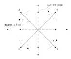
도4는 본 발명에 따른 무접점 충전 시스템에 구비되는 직렬공진형 컨버터의 각 모드별 동작에 따른 자계의 회전 방향을 도시한 예시도.Figure 4 is an illustration showing the rotation direction of the magnetic field according to the operation of each mode of the series resonant converter provided in the contactless charging system according to the present invention.
도5는 본 발명에 따른 무접점 충전 시스템에 구비된 배터리팩의 구성을 도시한 사시도.Figure 5 is a perspective view showing the configuration of a battery pack provided in a contactless charging system according to the present invention.
도6은 본 발명에 따른 무접점 충전 시스템에 2차측코어부가 내장된 배터리팩이 올려졌을 때의 알고리즘을 도시한 예시도.6 is an exemplary diagram illustrating an algorithm when a battery pack having a secondary side core part is mounted in a contactless charging system according to the present invention.
도7은 본 발명에 따른 무접점 충전 시스템에 금속인 이물체가 올려졌을 때의 알고리즘을 도시한 예시도.7 is an exemplary diagram showing an algorithm when a foreign object that is a metal is placed on a contactless charging system according to the present invention.
도8은 본 발명에 따른 무접점 충전 시스템의 알고리즘과 그 상태를 도시한 예시도.8 is an exemplary diagram showing an algorithm and a state of a contactless charging system according to the present invention.
<도면의 주요부분에 대한 부호의 설명><Description of the symbols for the main parts of the drawings>
A:무접점 충전기 B:배터리팩A: Solid state charger B: Battery pack
100:전자파 필터 110:1차정류회로100: electromagnetic wave filter 110: 1st order rectifier circuit
110':플라이백 컨버터 120:직렬공진형 컨버터110 ': flyback converter 120: series resonant converter
130:1차측코어부 160:게이트 드라이버130: 1 primary side core 160: gate driver
170:전류검출부 180:중앙처리부170: current detector 180: central processing unit
182:이온발생부 183:온도보호회로부182: ion generating unit 183: temperature protection circuit
본 발명은 무접점 충전 시스템에 관한 것으로, 더욱 상세하게는 무접점 충전기의 패드에 올려진 휴대용 단말기나 배터리팩 및 이물질을 검출하고 이를 통해 충전상태 감시 및 제어를 효율적으로 수행할 수 있도록 함으로써, 패드위에 올려진 이물질이 유도가열현상에 의하여 가열되는 것을 방지하고, 아울러 이들을 충전하는 과정에서 음이온이 동시에 발생되어지도록 함으로써, 단말기의 잔류된 세균을 살균하도록 하고, 그 주변 공기를 쾌적하게 유지할 수 있도록 한 것이다.The present invention relates to a contactless charging system, and more particularly, by detecting a portable terminal, a battery pack, and a foreign material mounted on a pad of a contactless charger, thereby enabling the charging state monitoring and control to be efficiently performed. It prevents foreign substances on the top from being heated by induction heating, and also generates negative ions at the same time while charging them to sterilize residual bacteria in the terminal and keep the surrounding air pleasant. will be.
일반적으로 통신 및 정보 처리 기술이 발달됨에 따라 휴대폰 등과 같이 휴대하기 편리한 휴대용 디바이스들의 사용이 점차적으로 증가되고 있으며, 기술의 발달에 따라 성능이 향상된 새로운 모델의 단말기가 계속적으로 보급되는 추세이다.In general, as communication and information processing technologies are developed, the use of portable devices, such as mobile phones, that are convenient to carry is gradually increasing, and as the technology develops, new models of terminals having improved performance are continuously being used.
이러한 휴대용 디바이스의 충전에는 접촉형 충전 방식이나 접촉 단자가 외부로 노출됨에 따른 접촉형 충전 방식의 문제점을 해결하기 위하여 전기적 접촉 없이 자기 결합을 이용하여 배터리를 충전하는 무접점 충전 방식이 사용되고 있다.In order to solve the problem of the contact type charging method or the contact type charging method due to exposure of the contact terminals to the outside, a contactless charging method of charging a portable device using a magnetic coupling without electrical contact is used.
이와 같은 무접점 충전기에 해당하는 기술로는 선출원 공개된 공개특허공보 제2002-0035242호 '유도 결합에 의한 휴대 이동 장치용 축전지의 비접촉식충전 장치'와 같이 자성체 코어를 이용하여 배터리팩과 충전장치 사이에 무선통신에 의하여 충전하는 방식, 선출원 공개된 공개특허공보 제2002-0057469호 '코어 없는 초박형 프린트회로기판 변압기 및 그 프린트회로기판 변압기를 이용한 무접점 배터리 충전기'와 같이 권선을 프린트회로기판에 형성한 변압기를 사용하여 자성체 코어의 문제점을 해결하는 방식 등이 제안되고 있다.As a technology corresponding to the contactless charger, a magnetic core is used between a battery pack and a charging device, such as a non-contact charging device of a storage battery for a portable mobile device by induction coupling, published in Korean Patent Application Publication No. 2002-0035242. To form a winding on a printed circuit board, such as a method of charging by wireless communication, a published patent application No. 2002-0057469 discloses an ultra-thin printed circuit board transformer without a core and a contactless battery charger using the printed circuit board transformer. A method of solving a problem of a magnetic core using a transformer has been proposed.
본 출원인은 선출원된 "무선주파수 식별기술이 적용된 무선 충전용 패드 및 배터리팩(출원번호 제2004-48286호)" 등을 통해, 무접점 충전기의 기능을 수행하는 무선 충전용 패드를 구성하고, 무선 충전용 패드에 휴대용 디바이스의 배터리팩을 올려 놓아 무접점으로 충전되도록 하는 기술을 제안한 바 있다.Applicant has configured a wireless charging pad that performs the function of a contactless charger through a previously filed "wireless charging pad and battery pack (application number 2004-48286) applied with radio frequency identification technology," A technology for charging a contactless device by placing a battery pack of a portable device on a charging pad has been proposed.
그러나, 이 같은 종래의 기술은 무접점 충전용 패드측에서 올려진 휴대용 디바이스나 배터리팩을 검출함에 있어, 리더 안테나를 통해 알에프 캐리어 신호를 외부로 무선 전송한 후 리턴되는 신호 유무를 검사하는 방식에 의존하고 있어, 배터리팩 검출과 이를 통한 충전상태 감시 및 제어가 제한적으로 이루어질 수 있다는 문제점이 있었다.However, such a conventional technique is to detect a portable device or a battery pack mounted on the contactless charging pad side, and to check whether there is a signal returned after wireless transmission of the RF carrier signal through the reader antenna to the outside. As a result, there has been a problem that battery pack detection and charging state monitoring and control through the battery pack can be limited.
또한, 무접점 충전용 패드에 배터리팩이나 휴대용 단말기나 배터리팩 이외에 동전, 금속펜, 가위 등(이하,'이물체'라함)이 올려졌을 경우에도 전력송신이 계속 진행됨으로써, 유도가열현상으로 인하여 올려져 있는 이물체가 가열되는 문제점이 있었다.In addition, even when coins, metal pens, scissors, etc. (hereinafter referred to as "foreign objects") are placed on the contactless charging pad in addition to the battery pack, the portable terminal, or the battery pack, the induction heating phenomenon may occur. There was a problem that the foreign material on the heating is heated.
그리고, 무접점 충전용 패드가 단말기나 배터리팩을 충전시키는 단순한 기능만을 가짐으로써, 그 효율성이 낮아지는 또 다른 문제점이 있었다.In addition, the contactless charging pad has only a simple function of charging the terminal or the battery pack, and thus there is another problem that the efficiency is lowered.
따라서, 본 발명은 이와 같은 문제점을 해소하기 위하여 창출한 것으로, 무접점 충전용 패드에 올려진 휴대용 디바이스나 배터리팩 및 이물질을 종류별로 검출하고 이를 통해 충전상태 감시 및 제어를 효율적으로 수행함과 동시에 이물질이 고온으로 가열되어지는 것을 방지할 수 있도록 하는데 있다.Accordingly, the present invention has been created to solve such a problem, and detects a portable device, a battery pack, and a foreign material on a contactless pad for each type and efficiently monitors and controls the state of charge through the foreign matter and at the same time. This is to prevent the heating to a high temperature.
또한, 무접점 충전용 패드에 단말기의 살균기능과 함께 음이온이 발생되어지도록 함으로써, 단말기를 청결하게 사용할 수 있도록 하고, 아울러 주변의 공기를 쾌적하게 유지할 수 있도록 하는데 있다.In addition, by allowing the non-contact charging pad to generate negative ions along with the sterilization function of the terminal, it is possible to use the terminal cleanly, and to maintain the surrounding air comfortably.
그리고 무접점 충전용 패드에 구비되는 1차측코어부의 중앙이 비어있는 형태로 제공되어지도록 함으로써, 보다 단순화된 구조를 가지면서 동시에 임의 위치에서도 충전이 가능하도록 하여 사용효율을 높일 수 있도록 하는데 그 목적이 있다.And the center of the primary side core portion provided in the contactless charging pad is to be provided in an empty form, to have a simplified structure and at the same time can be charged at any position to increase the efficiency of use have.
이와 같음 목적을 달성하기 위한 본 발명은 전원이 입력되는 무접점 충전기(A)로 부터 발생되는 유도기전력에 의하여 충전되어지는 배터리팩(B)으로 구성된 무접점 충전 시스템에 있어서, 상기 무접점 충전기(A)는 전원입력단에 결합되어 입력된 AC 전원의 전자파를 차단하는 전자파 필터(100); 전자파가 차단된 AC 전원을 DC로 정류하는 1차정류회로(110); 내장된 트랜지스터가 온 상태인 동안 상기 1차정 류회로(110)로부터 전달된 전력을 축적하여, 오프 되는 순간에 게이트 드라이버(160)와 중앙처리부(180) 및 이온발생부(182)로 입력전압을, 직렬공진형 컨버터(120)로 구동전압을 각각 인가하는 플라이백 컨버터(110'); 상기 플라이백 컨버터(110')와 상기 직렬공진형 컨버터(120) 간에 게재되어 배터리팩(B) 접근에 따른 전류 변화를 검출하고, 전류 변화량에 따른 비교전류를 출력하는 전류검출부(170); 상기 전류검출부(170)로부터 입력된 비교전류를 이용해 배터리팩(B)의 접근을 감지하고, 접근 여부에 따라 게이트 드라이버(160)를 제어하고, 이상동작이나 이물질이 올려져 설정된 온도이상으로 상승했을때 스위칭을 차단시켜주기 위한 온도보호회로부(183)의 전류에 따라 상기 게이트 드라이버(160)를 제어하는 중앙처리부(180); 상기 중앙처리부(180)의 제어에 의해 게이트 신호를 출력하는 게이트 드라이버(160); 상기 게이트 드라이버(160)로부터 입력되는 게이트 신호에 의해 1차측코어부(130)로 흐르는 전압 및 전류 파형을 조절하는 상기 직렬공진형 컨버터(120); 상기 직렬공진형 컨버터(120)에 의해 스위칭되어 유도기전력을 발생시키는 상기 1차코어부(130)로 구성된 것을 특징으로 한다.The present invention for achieving the above object in the contactless charging system consisting of a battery pack (B) is charged by induction electromotive force generated from a contactless charger (A) is a power input, the contactless charger ( A) is coupled to the power input terminal
상기 게이트 드라이버(160)는 중앙처리부(180)의 제어에 의해 출력되는 게이트 신호를 통해 상기 직렬공진형 컨버터(120)에 구비된 두 개의 스위칭 소자가 교대로 켜지도록 하여 각각의 스위칭 소자에 결합된 병렬 커패시터의 충·방전을 통해 1차측코어부(130)로 입력되는 전압 및 전류 파형을 조절하도록 된 것을 특징으로 한다.The
상기 전류검출부(170)는 상기 플라이백 컨버터(110') 출력단과 상기 직렬공 진형 컨버터(120) 입력단을 연결하는 저항의 양단에 접속된 것으로 저항 양단 신호가 입력되는 차등증폭기(171) 및 상기 차등증폭기(171) 출력단에 결합된 비교기/저주파 필터(172)로 구성되어 상기 차등증폭기(171)의 출력을 미리 설정된 기준전압과 비교하여 전류 변화를 검출하고, 전류 변화량에 따른 비교전류를 필터링하여 출력하도록 된 것을 특징으로 한다.The
상기 중앙처리부(180)는 먼지, 악취센서(181)로 부터 피드백된 정보를 판단하여 이온발생부(182)의 작동모드를 전환시켜주도록 구성됨을 특징으로 한다.The
상기 1차코어부(130)는 중공부(132)가 형성된 평판코어부재(131)의 가장자리에 코일(Pcoil,Pcoil2)이 권선되어지도록 구성됨을 특징으로 한다.The
상기 평판코어부재(131)는 다각형이나 원형 및 타원형 중 어느 하나로 구성되어진 것으로 비정질 금속이나 페라이트 재질로 된 조각이 부착되어지도록 구성됨을 특징으로 한다.The flat
상기 코일(Pcoil,Pcoil2)은 평판코어부재(131)의 가장자리에 직렬이나 병렬형태로 감겨지도록 구성됨을 특징으로 한다.The coils Pcoil and Pcoil2 may be wound around the edges of the flat
상기 배터리팩(B)은 1차측코어부(130)를 통해 전력이 유도되는 2차측코어부(210); 상기 2차측코어부(120)의 코일(Scoil1)에 결합되어 유도된 전력을 정류하는 2차정류회로(200); 상기 2차정류회로(200)에서 정류된 전력을 이물질감지부(220)에 공급하고, 상기 이물질감지부(220)의 출력에 따라 충전조절회로(230a) 및 상기 충전조절회로(230a)로부터 공급된 전력을 보호회로부(240)를 통해 배터리(BAT)에 공급하고, 상기 배터리(BAT)의 충전상태를 모니터링하여 충전상태정보를 생성하여 주 기적으로 기록하는 퓨얼 게이지(210b)로 구성되는 충전제어부(230); 상기 충전제어부(230) 및 상기 배터리(BAT) 사이에 결합되어 상기 배터리(BAT)의 충전상태에 따라 충·방전 여부를 조절하는 보호회로부(240)로 구성됨을 특징으로 한다.The battery pack B includes a secondary
상기 배터리팩(B)의 2차측코어부(210)와 배터리케이스(250) 사이에 박막형태를 갖는 차폐판(260)이 개재되어지도록 구성하고, 상기 보호회로부(240)에 차폐부재(241)가 감싸여지도록 구성됨을 특징으로 한다.A
상기 충전제어부(230)는 상기 2차정류회로(200)를 통해 정류된 전력을 이용해 배터리(BAT)의 충전여부를 제어하는 충전제어기능과 상기 배터리(BAT)의 충전상태를 모니터링하여 충전상태정보를 생성해 주기적으로 기록하는 퓨얼 게이지 기능을 동시에 수행하도록 최적화된 회로로 집적되어짐을 특징으로 한다.The
그리고 상기 이물질감지부(220)는 무접점 충전기(A)에 2차측코어부(210)가 실장된 배터리팩(B)을 올려 놓음과 동시 전원를 감지하여 일정시간 동안
이하, 본 발명의 실시예를 첨부 도면을 참조하여 설명하면 다음과 같다.Hereinafter, an embodiment of the present invention will be described with reference to the accompanying drawings.
먼저, 본 발명을 설명함에 있어 관련된 공지 기능 또는 구성에 대한 구체적 인 설명이 본 발명의 요지를 불필요하게 흐릴 수 있다고 판단되는 경우 그 상세한 설명은 생략하기로 한다.First, in describing the present invention, when it is determined that a detailed description of a related known function or configuration may unnecessarily obscure the subject matter of the present invention, the detailed description thereof will be omitted.
도1은 본 발명에 따른 무접점 충전 시스템의 구성을 도시한 예시도이다.1 is an exemplary view showing the configuration of a contactless charging system according to the present invention.
본 발명에 따른 무접접 충전 시스템은 전원이 입력되는 무접점 충전기(A)로 부터 발생되는 유도기전력에 의하여 충전되어지는 배터리팩(B)으로 구성되어 있다.The contactless charging system according to the present invention comprises a battery pack (B) that is charged by induction electromotive force generated from a contactless charger (A) to which power is input.
여기에서, 상기 무접점 충전기(A)는 도시된 바와 같이, 무선 충전용 패드(A)의 전원입력단에 접속된 전자파 필터(100)에 의하여 입력된 AC 전원(110/220V)의 전자파를 차단하고, 1차정류회로(110)는 전자파가 차단된 AC 전원을 DC로 정류한다. 플라이백 컨버터(110')는 트랜지스터를 내장하여 내장된 트랜지스터가 온 상태인 동안 1차정류회로(110)로부터 전달되는 전력을 축적하여, 오프 되는 순간에 게이트 드라이버(160)와 중앙처리부(180) 및 이온발생부(182)로 입력전압을 인가함과 동시에 직렬공진형 컨버터(120)로 구동전압을 각각 인가한다.Here, the contactless charger (A) as shown, and cuts the electromagnetic wave of the AC power (110 / 220V) input by the
전류검출부(170)는 상기 플라이백 컨버터(110')와 상기 직렬공진형 컨버터(120) 간에 게재되어 배터리팩(B) 접근에 따른 전류 변화를 검출하고, 전류 변화량에 따른 비교전류를 출력한다.The
이를 위해, 상기 전류검출부(170)는 상기 플라이백 컨버터(110') 출력단과 상기 직렬공진형 컨버터(120) 입력단을 연결하는 저항의 양단에 접속된 것으로 저항 양단 신호가 입력되는 차등증폭기(171) 및 상기 차등증폭기(171) 출력단에 결합된 비교기/저주파 필터(172)로 구성되어 상기 차등증폭기(171)의 출력을 미리 설정된 기준전압과 비교하여 전류 변화를 검출하고, 전류 변화량에 따른 비교전류를 필 터링하여 출력한다.To this end, the
중앙처리부(180)는 전류검출부(170)로부터 입력된 비교전류를 이용해 배터리팩(B)의 접근을 감지하고, 접근 여부에 따라 게이트 드라이버(160)를 제어함과 동시에 이상동작이나 이물질이 올려져 설정된 온도이상으로 상승했을때 스위칭을 차단시켜주기 위한 온도보호회로부(183)의 전류에 따라 상기 게이트 드라이버(160)를 제어한다. 또한, 상기 중앙처리부(180)는 먼지, 악취센서(181)로 부터 피드백된 정보를 판단하여 이온발생부(182)의 작동모드를 전환시킨다.The
게이트 드라이버(160)는 중앙처리부(180)의 제어에 의해 게이트 신호를 출력하고, 직렬공진형 컨버터(120)는 게이트 드라이버(160)로부터 입력되는 게이트 신호에 의해 1차측코어부(130)로 흐르는 전압 및 전류 파형을 조절한다.The
이를 위해, 상기 게이트 드라이버(160)는 중앙처리부(180)의 제어에 의해 출력되는 게이트 신호를 통해 상기 직렬공진형 컨버터(120)에 구비된 두 개의 스위칭 소자가 교대로 켜지도록 하여 각각의 스위칭 소자에 결합된 병렬 커패시터의 충·방전을 통해 1차측 코어부(130)로 입력되는 전압 및 전류 파형을 조절되어지도록 구성되어 있다.To this end, the
직렬공진형 컨버터(120)는 상기 게이트 드라이버(160)로부터 입력되는 게이트 신호에 의해 1차측코어부(130)로 흐르는 전압 및 전류 파형을 조절하도록 구성되어 있다. 상기 1차코어부(130)는 직렬공진형 컨버터(120)에 의해 스위칭되어 유도기전력을 발생시키도록 구성되어 있다.The series
도2a,2b는 본 발명에 따른 무접점 충전 시스템에 개재되는 1차측코어부를 도 시한 사시도이고, 도3a,3b는 본 발명에 따른 무접점 충전 시스템에 개재되는 1차측코어부의 사용상태를 도시한 사시도이다.Figures 2a, 2b is a perspective view showing a primary side core part interposed in a contactless charging system according to the present invention, Figures 3a, 3b is a state of use of the primary side core part interposed in a contactless charging system according to the present invention. Perspective view.
도시된 바와 같이 상기 1차코어부(130)는 중공부(132)가 형성된 평판코어부재(131)의 가장자리에 코일(Pcoil,Pcoil2)이 권선된 것으로 코발트(Co), 철(Fe), 니켈(Ni), 붕소(B), 규소(Si) 등 높은 투자율(>80,000)과 깨지지 않는 성질을 가진 코발트 계열의 비정질금속 또는 페라이트 재질된 조각이 부착되어지도록 구성되어 있다. 이러한, 상기 평판코어부재(131)는 다각형으로 구성하였으나, 이러한 형태 이외에 원형 및 타원형 중 어느 하나로 형성되어지도록 할 수 있다. 중공부(132)는 소재의 사용량을 줄임과 동시에 방열면적을 극대화시킬 수 있는 기능이 제공되어지도록 구성되어 있다.As shown in the drawing, the
상기 코일(Pcoil,Pcoil2)은 평판코어부재(131)의 가장자리에 직렬이나 병렬형태로 감겨지도록 구성된 것으로 단선이나 이중선 및 리쯔선 그리고 동박 등을 사용하는 것이 더욱 바람직하다. 코일(Pcoil,Pcoil2)의 시작점은 동일한 방향으로 감아 만들고, 각각의 끝에는 도1에 도시된 바와 같이, 1차측코어부(130)의 Lr과 Lr'에 매치시켜 2개의 직력공진 컨버터를 이용하여 각각 스위칭을 하여 구성시킬 수 있다.The coils (Pcoil, Pcoil2) is configured to be wound in series or parallel on the edge of the flat
이때 구동되어지는 스위칭은

또한, 코일(Pcoil,Pcoil2)의 스위칭 패턴이 교번됨으로써, 도4에 도시된 바 와 같은 자장이 360°회전하는 효과를 볼 수 있으며, 단일 방향으로 권선한 2차측의 위치에 상관없이 유기된 에너지를 받을 수 있게 된다.In addition, by switching the switching patterns of the coils Pcoil and Pcoil2, the magnetic field as shown in FIG. 4 is rotated 360 °, and the induced energy is irrespective of the position of the secondary side wound in a single direction. Will be able to receive.
한편, 이와 같은 구성을 갖는 1차측코어부(130)를 도3a,3b에 도시된 바와 같이 회로(134)의 일측이나 양측에 개재하여 사용할 경우, 복수개의 휴대용 단말기나 배터리팩을 동시에 충전함으로써 그 효율을 높일 수 있게 된다.On the other hand, when the primary
또한, 도3c에 도시된 바와같이, 회로(134)의 일측에 다른 1차측코어부(130(130")를 병렬이나 직렬로 개배되어지도록 사용할 수 있다.In addition, as shown in FIG. 3C, the other primary side core portion 130 (130 ″) may be used in parallel or in series on one side of the
도1에 도시된 바와 같이, 배터리팩(B)은 2차측코어부(120)의 코일(Scoil1)을 통해 1차측코어부(130)으로 부터 전력이 공진커패서터(Cs)를 경유하면서 공진이 발생되어지고, 공진에 의해 발생된 정현적 AC가 2차정류회로(200)에 의하여 DC로 정류된다.As shown in FIG. 1, the battery pack B resonates while power is supplied from the
상기 2차정류회로(200)에서 정류된 전력이 이물질감지부(220)에 공급하고, 상기 이물질감지부(220)의 출력에 따라 충전조절회로(230a)로 인가시킨다.Power rectified by the
여기에서, 상기 이물질감지부(220)는 무접점 충전기(A)위에 2차측 모듈인 2차측코어부(210)가 내장된 배터리팩(B)을 올려 놓는 순간 전원를 감지하여 일정시간(수십ms) 동안
또한, 충전이 종료됨과 동시에 다시 2차측코어부(210)가 무부하상태로 되기때문에 전류검출부(170)의 전류가 무부하 상태인 기준치 이하가 되어 만충전 상태가 LED 또는 LCD에 표시된다.In addition, since charging is completed and the secondary
충전제어부(210)는 충전조절회로(230a)와 퓨얼 게이지(230b)를 구비하여 충전조절기능과 퓨얼 게이지 기능을 동시에 수행한다. 충전조절회로(230a)는 2차정류회로(200)에서 정류된 전력을 퓨얼 게이지(230b)에 공급하고, 2차정류회로(200)의 출력에 따라 미도시한 알에프아이디 제어부로 전압을 인가한다. 퓨얼 게이지(230b)는 충전조절회로(230a)로부터 공급된 전력을 보호회로부(240)를 통해 배터리(BAT)에 공급하고, 배터리(BAT)의 충전상태를 모니터링하여 충전상태정보를 생성해 알에프아이디 제어부에 주기적으로 기록한다. 보호회로(240)는 충전제어부(230) 및 배터리(BAT) 사이에 결합되어 배터리(BAT)의 충전상태에 따라 충·방전 여부를 조절하여 배터리(BAT)를 보호한다.The
미도시한 알에프아이디 제어부는 배터리(BAT)의 무선식별정보가 저장됨과 동시에 충전상태정보가 주기적으로 기록되며, 태그 안테나로 알에프 캐리어 신호가 수신되면 그 응답으로 저장되어 있는 배터리(BAT)의 무선식별정보 및 충전상태정보를 포함하여 알에프 데이터를 생성하고, 이를 변조하여 변조된 알에프 데이터를 태그 안테나를 통해 무선 전송한다. 배터리(BAT)는 보호회로부(240)의 조절에 따라 충전된다.The RF ID controller, which is not shown, stores the wireless identification information of the battery BAT and periodically records the charging state information. When the RFID carrier signal is received by the tag antenna, the wireless identification of the battery BAT stored in the response is performed. RF data is generated, including the information and the charging state information, and the modulated RF data is wirelessly transmitted through the tag antenna. The battery BAT is charged according to the control of the
상기 충전제어부(230)는 상기 2차정류회로(200)를 통해 정류된 전력을 이용 해 배터리(BAT)의 충전여부를 제어하는 충전제어기능과 상기 배터리(BAT)의 충전상태를 모니터링하여 충전상태정보를 생성해 주기적으로 기록하는 퓨얼 게이지 기능을 동시에 수행하도록 최적화된 회로로 집적되어지도록 구성된다.The
도5는 본 발명에 따른 무접점 충전 시스템에 구비된 배터리팩의 구성을 도시한 사시도로서, 도시된 바와 같이, 상기 배터리팩(B)의 2차측코어부(210)와 배터리케이스(250) 사이에 박막형태를 갖는 차폐판(260)이 개재되어지도록 구성되어 자기장이 유도되면서 발생되는 유도기전력으로 인하여 배터리의 온도가 상승되는 것을 방지하여 그 안정성을 높일 수 있도록 하고, 동시에 유도기전력으로 인한 자장의 간섭을 줄여 2차측코어부(210)에 충분한 기전력이 발생되도록 하여 충전율을 높일 수 있도록 구성되어 있다.Figure 5 is a perspective view showing the configuration of a battery pack provided in a contactless charging system according to the present invention, as shown, between the secondary
또한, 보호회로부(240)에 자기장을 차폐할 수 있는 차폐부재(241)가 감싸여지도록 구비하여 사용할 경우, 보호회로부(240)의 내부에 구비된 다른 부품에 영향을 주는 것을 막을 수 있다. 이러한 차폐부재(241)는 박스형태로 구비하여 씌워지도록 사용할 수 있으며, 바람직하기로는 보호회로부(240) 전부가 몰딩으로 처리되어지도록 하는 것이 더욱 바람직하다.In addition, when the shielding
무선 충전용 패드(A)를 통해 배터리팩(B)이 충전되는 과정의 일례를 도6 내지 도8을 참조하여 살펴보면 다음과 같다.An example of a process of charging the battery pack B through the wireless charging pad A will now be described with reference to FIGS. 6 to 8.
도6은 본 발명에 따른 무접점 충전 시스템에 2차측코어부가 내장된 배터리팩이 올려졌을 때의 알고리즘을 도시한 예시도이고, 도7은 본 발명에 따른 무접점 충전 시스템에 금속인 이물체가 올려졌을 때의 알고리즘을 도시한 예시도이고, 도8은 본 발명에 따른 무접점 충전 시스템의 알고리즘과 그 상태를 도시한 예시도이다.6 is an exemplary diagram illustrating an algorithm when a battery pack having a secondary side core unit is mounted in a contactless charging system according to the present invention, and FIG. 7 is a foreign material of a metal in the contactless charging system according to the present invention. 8 is an exemplary diagram showing an algorithm when raised, and FIG. 8 is an exemplary diagram showing an algorithm and a state of a contactless charging system according to the present invention.
우선, 배터리팩(B)을 무선 충전용 패드(A) 위에 놓음과 동시에 이물질감지부 (220)가 순간 전원을 감지하여 수초 동안
다음, 전류검출부(170)의 전류가 무부하 기준치 보다 작은 상태를 지속하다가 수초가 지난 후 수위치를 온상태로 유지시켜 부하상태로 전환되어지도록 한다. 즉, 전류검출부(170)의 전류가 무부하 기준치보다 큼으로 이를 전환하여 무접점 충전기(A)에 2차측코어부(210)가 내장된 배터리팩(B)이 올려져 있다고 부하변조를 통해 그 상태를 1차측에 알려줌과 동시에 충전제어부(230)로 전력을 인가시킨다.Next, while the current of the
다음, 충전이 종료됨과 동시에 다시 2차측코어부(210)가 무부하상태로 되기때문에 전류검출부(170)의 전류가 무부하 상태인 기준치 이하가 되어 만충전 상태가 됨으로써, 미도시한 LED 또는 LCD에 표시가 된다.Next, since charging is completed and the secondary
충전제어부(230)로 전력이 인가됨과 동시에 중앙처리부(180)에 의하여 악취센서(181)로 부터 피드백된 정보를 판단하여 이온발생부(182)의 작동모드를 전환시킴으로써 이온발생부(182)를 통해 다량의 이온이 발생되어 무선 충전용 패드(A)의 주변으로 확산되어 배터리팩(B)에 잔류된 세균을 살균시킴과 동시에 그 주변의 공기를 정화시킬 수 있게 된다.The power is supplied to the
한편, 이물질을 무선 충전용 패드(A) 위에 놓음과 동시에 이물질감지부 (220)가 순간 전원을 감지하여 수초 동안
상기 본 발명은 당업자의 요구에 따라 기본 개념을 벗어나지 않는 범위 내에서 다양한 변형이 가능하다.The present invention may be modified in various ways without departing from the basic concept according to the needs of those skilled in the art.
이와 같이 본 발명은 무선 충전용 패드의 윗면에 올려진 휴대용 디바이스나 배터리팩 및 이물질을 각각 검출하고 이를 통해 충전상태 감시 및 제어를 효율적으로 수행할 수 있도록 하기 위한 구성요소들이 추가되어 전체적인 회로 성능을 개선하고, 아울러 이물질이 고온으로 가열되어지는 것을 방지할 수 있도록 하는데 있다.As described above, the present invention adds components for detecting a portable device, a battery pack, and a foreign material on the top surface of the wireless charging pad, and efficiently performing the monitoring and control of the charging state. In addition, it is possible to prevent the foreign material from being heated to a high temperature.
또한, 무선 충전용 패드에 단말기의 살균기능과 함께 음이온이 발생되어지도록 함으로써, 단말기를 청결하게 사용할 수 있도록 하고, 아울러 주변의 공기를 쾌적하게 유지할 수 있도록 하는데 있다.In addition, by allowing anion to be generated along with the sterilization function of the terminal to the wireless charging pad, it is possible to use the terminal cleanly, and also to maintain the surrounding air comfortably.
그리고 무선 충전용 패드에 구비되는 1차측코어부를 가운데가 비어있는 형태로 제공되어지도록 함으로써, 보다 단순화된 구조를 가지면서 동시에 임의 위치에서도 충전이 가능하도록 하여 사용효율을 높일 수 있도록 하는데 있다.In addition, by providing the primary side core part provided in the wireless charging pad in the form of an empty center, it has a more simplified structure and at the same time can be charged at any position to increase the use efficiency.
Claims (11)
Translated fromKorean
Priority Applications (11)
| Application Number | Priority Date | Filing Date | Title |
|---|---|---|---|
| KR1020050023184AKR100554889B1 (en) | 2005-03-21 | 2005-03-21 | Contactless charging system |
| US12/914,303USRE44038E1 (en) | 2005-03-21 | 2005-04-11 | No point of contact charging system |
| EP05804905AEP1882292A4 (en) | 2005-03-21 | 2005-04-11 | CHARGING SYSTEM WITHOUT POINT OF CONTACT |
| EP11178723.0AEP2390984B1 (en) | 2005-03-21 | 2005-04-11 | Battery pack with an object detection unit |
| JP2007509392AJP4258568B2 (en) | 2005-03-21 | 2005-04-11 | Contactless charging system |
| US13/750,494USRE48193E1 (en) | 2005-03-21 | 2005-04-11 | No point of contact charging system |
| US10/570,041US7443135B2 (en) | 2005-03-21 | 2005-04-11 | No point of contact charging system |
| EP19159706.1AEP3525315B1 (en) | 2005-03-21 | 2005-04-11 | Non-contact charging method |
| PCT/KR2005/001037WO2006101285A1 (en) | 2005-03-21 | 2005-04-11 | No point of contact charging system |
| CNB2005800006685ACN100362725C (en) | 2005-03-21 | 2005-04-11 | Contactless Charging System |
| US13/750,494US20130154559A1 (en) | 2005-03-21 | 2013-01-25 | No point of contact charging system |
Applications Claiming Priority (1)
| Application Number | Priority Date | Filing Date | Title |
|---|---|---|---|
| KR1020050023184AKR100554889B1 (en) | 2005-03-21 | 2005-03-21 | Contactless charging system |
Publications (1)
| Publication Number | Publication Date |
|---|---|
| KR100554889B1true KR100554889B1 (en) | 2006-03-03 |
Family
ID=37023921
Family Applications (1)
| Application Number | Title | Priority Date | Filing Date |
|---|---|---|---|
| KR1020050023184AExpired - LifetimeKR100554889B1 (en) | 2005-03-21 | 2005-03-21 | Contactless charging system |
Country Status (6)
| Country | Link |
|---|---|
| US (4) | USRE48193E1 (en) |
| EP (3) | EP1882292A4 (en) |
| JP (1) | JP4258568B2 (en) |
| KR (1) | KR100554889B1 (en) |
| CN (1) | CN100362725C (en) |
| WO (1) | WO2006101285A1 (en) |
Cited By (19)
| Publication number | Priority date | Publication date | Assignee | Title |
|---|---|---|---|---|
| KR100750201B1 (en) | 2006-06-14 | 2007-08-17 | 주식회사 한림포스텍 | Contactless outlet device for contactless power transmission to home appliance with contactless charger and its method |
| WO2009104832A1 (en)* | 2008-02-20 | 2009-08-27 | Chun-Kil Jung | Charging control method of non-contact charging system of wireless power transmision and chrging control method thereof |
| KR100971737B1 (en)* | 2007-11-30 | 2010-07-21 | 정춘길 | Multi contactless charging system and control method |
| KR100971734B1 (en)* | 2007-11-30 | 2010-07-21 | 정춘길 | Contactless power transmission device capable of multi-contact charging |
| KR100971748B1 (en)* | 2007-11-30 | 2010-07-22 | 정춘길 | Short range wireless power transfer system |
| KR100992480B1 (en) | 2009-09-10 | 2010-11-05 | 주식회사 한림포스텍 | Non-contact charging system having function for detecting foreign material using feedback signal |
| KR100998683B1 (en)* | 2007-11-30 | 2010-12-07 | 정춘길 | Contactless power receiver capable of multi-contact power charging |
| US7956575B2 (en) | 2006-04-28 | 2011-06-07 | Hitachi Koki Co., Ltd. | Charging device for battery |
| KR101061646B1 (en) | 2007-02-20 | 2011-09-01 | 세이코 엡슨 가부시키가이샤 | Transmission Control Units, Transmission Units, Electronic Devices and Solid State Power Transmission Systems |
| US8102147B2 (en) | 2007-11-30 | 2012-01-24 | Chun-Kil Jung | Wireless multi-charger system and controlling method thereof |
| KR101110282B1 (en)* | 2010-07-16 | 2012-02-15 | 정춘길 | Contactless power transmission control method of a contactless power receiver and a contactless power transmitter |
| CN102545398A (en)* | 2012-01-20 | 2012-07-04 | 北京科技大学 | Non-contact power supply device for axle load electronic equipment in rotator |
| KR101188241B1 (en) | 2010-07-15 | 2012-10-05 | 주식회사 만도 | Battery charger using common power source for electric vehicle |
| KR101441994B1 (en) | 2012-11-14 | 2014-09-18 | 파나소닉 주식회사 | Contactless power supplying device |
| KR101698045B1 (en)* | 2016-09-05 | 2017-01-20 | 김재범 | Air purifier comprising wireless charging device |
| KR101788204B1 (en)* | 2013-08-09 | 2017-10-19 | 인텔 코포레이션 | Coil for mobile device context-driven switching and wireless charging |
| CN110268597A (en)* | 2017-02-08 | 2019-09-20 | 三菱电机工程技术株式会社 | Transmission of electricity side apparatus |
| KR20220000488A (en)* | 2020-06-26 | 2022-01-04 | 이종성 | Mobile phone charger having sterilization function |
| US12322971B2 (en) | 2008-12-12 | 2025-06-03 | Intel Corporation | Non-contact power receiver apparatus |
Families Citing this family (189)
| Publication number | Priority date | Publication date | Assignee | Title |
|---|---|---|---|---|
| KR100554889B1 (en) | 2005-03-21 | 2006-03-03 | 주식회사 한림포스텍 | Contactless charging system |
| US7825543B2 (en) | 2005-07-12 | 2010-11-02 | Massachusetts Institute Of Technology | Wireless energy transfer |
| CN101860089B (en) | 2005-07-12 | 2013-02-06 | 麻省理工学院 | wireless non-radiative energy transfer |
| US8169185B2 (en) | 2006-01-31 | 2012-05-01 | Mojo Mobility, Inc. | System and method for inductive charging of portable devices |
| US7952322B2 (en) | 2006-01-31 | 2011-05-31 | Mojo Mobility, Inc. | Inductive power source and charging system |
| US11201500B2 (en) | 2006-01-31 | 2021-12-14 | Mojo Mobility, Inc. | Efficiencies and flexibilities in inductive (wireless) charging |
| CN101038616B (en)* | 2006-03-17 | 2010-05-12 | 上海华虹集成电路有限责任公司 | Limiting amplitude protection circuit used in non-contact IC card and radio frequency identification label |
| US11329511B2 (en) | 2006-06-01 | 2022-05-10 | Mojo Mobility Inc. | Power source, charging system, and inductive receiver for mobile devices |
| US7948208B2 (en) | 2006-06-01 | 2011-05-24 | Mojo Mobility, Inc. | Power source, charging system, and inductive receiver for mobile devices |
| US8004235B2 (en)* | 2006-09-29 | 2011-08-23 | Access Business Group International Llc | System and method for inductively charging a battery |
| EP1914669B1 (en) | 2006-10-18 | 2011-04-20 | Semiconductor Energy Laboratory Co., Ltd. | RFID tag |
| KR100836634B1 (en)* | 2006-10-24 | 2008-06-10 | 주식회사 한림포스텍 | Portable terminal using a contactless charger, a battery pack for charging and a contactless charger for wireless data communication and power transmission |
| US20100328044A1 (en)* | 2006-10-26 | 2010-12-30 | Koninklijke Philips Electronics N.V. | Inductive power system and method of operation |
| EP2086085B1 (en)* | 2006-11-08 | 2015-04-15 | Panasonic Corporation | Non-contact charger and non-contact charge system |
| US20080136364A1 (en)* | 2006-12-08 | 2008-06-12 | Russell Calvarese | Battery charging using thermoelectric devices |
| JP5325415B2 (en)* | 2006-12-18 | 2013-10-23 | 株式会社半導体エネルギー研究所 | Semiconductor device |
| EP1973069B1 (en) | 2007-03-22 | 2013-01-02 | Semiconductor Energy Laboratory Co., Ltd. | Semiconductor device |
| US9466419B2 (en) | 2007-05-10 | 2016-10-11 | Auckland Uniservices Limited | Apparatus and system for charging a battery |
| KR102128564B1 (en) | 2007-05-10 | 2020-07-01 | 오클랜드 유니서비시즈 리미티드 | Multi power sourced electric vehicle |
| AU2008251143B2 (en)* | 2007-05-10 | 2011-12-22 | Auckland Uniservices Limited | Multi power sourced electric vehicle |
| US8115448B2 (en) | 2007-06-01 | 2012-02-14 | Michael Sasha John | Systems and methods for wireless power |
| US9421388B2 (en) | 2007-06-01 | 2016-08-23 | Witricity Corporation | Power generation for implantable devices |
| KR100819753B1 (en)* | 2007-07-13 | 2008-04-08 | 주식회사 한림포스텍 | Contactless charging system for battery pack solution and its control method |
| JP2009027781A (en)* | 2007-07-17 | 2009-02-05 | Seiko Epson Corp | Power reception controller, power receiver, contactless power transmitting system, charge controller, battery device, and electronic equipment |
| JP2009087928A (en) | 2007-09-13 | 2009-04-23 | Semiconductor Energy Lab Co Ltd | Semiconductor device and manufacturing method thereof |
| CA2701394A1 (en)* | 2007-10-17 | 2009-04-23 | Access Business Group International Llc | Laptop and portable electronic device wireless power supply systems |
| US8729734B2 (en)* | 2007-11-16 | 2014-05-20 | Qualcomm Incorporated | Wireless power bridge |
| WO2009065419A1 (en)* | 2007-11-20 | 2009-05-28 | Nokia Corporation | Wireless galvanic charging device, method of operation thereof and mobile electronic device to be charged |
| WO2009069201A1 (en)* | 2007-11-28 | 2009-06-04 | Olympus Medical Systems Corp. | Battery management system and charger |
| JP5556002B2 (en)* | 2008-01-09 | 2014-07-23 | セイコーエプソン株式会社 | Power transmission control device, power transmission device, non-contact power transmission system, and electronic device |
| WO2009114101A1 (en)* | 2008-03-03 | 2009-09-17 | Mitch Randall | Universal electrical interface for providing power to mobile devices |
| JP5188211B2 (en)* | 2008-03-07 | 2013-04-24 | キヤノン株式会社 | Power supply apparatus and power supply method |
| US8338990B2 (en)* | 2008-03-13 | 2012-12-25 | Access Business Group International Llc | Inductive power supply system with multiple coil primary |
| KR101094253B1 (en)* | 2008-04-28 | 2011-12-19 | 정춘길 | Non-contact power receier, non-contact power trasmitter related to the same and non-contact power transmitting and receiving system |
| US20110050164A1 (en) | 2008-05-07 | 2011-03-03 | Afshin Partovi | System and methods for inductive charging, and improvements and uses thereof |
| JP2009273327A (en)* | 2008-05-10 | 2009-11-19 | Sanyo Electric Co Ltd | Battery built-in apparatus and charging cradle |
| US20090284369A1 (en) | 2008-05-13 | 2009-11-19 | Qualcomm Incorporated | Transmit power control for a wireless charging system |
| JP4725664B2 (en)* | 2008-06-25 | 2011-07-13 | セイコーエプソン株式会社 | Power transmission control device, power transmission device, power reception control device, power reception device, electronic device, power transmission control method, and power reception control method |
| US8248024B2 (en)* | 2008-08-15 | 2012-08-21 | Microsoft Corporation | Advanced inductive charging pad for portable devices |
| EP2329429A4 (en)* | 2008-09-17 | 2015-07-29 | Semiconductor Energy Lab | Semiconductor device |
| GB0817047D0 (en)* | 2008-09-18 | 2008-10-22 | Amway Europ Ltd | Electromagnetic Interference Suppression |
| WO2010032603A1 (en) | 2008-09-19 | 2010-03-25 | Semiconductor Energy Laboratory Co., Ltd. | Semiconductor device and wireless tag using the same |
| US8963488B2 (en) | 2008-09-27 | 2015-02-24 | Witricity Corporation | Position insensitive wireless charging |
| US9544683B2 (en) | 2008-09-27 | 2017-01-10 | Witricity Corporation | Wirelessly powered audio devices |
| US9093853B2 (en) | 2008-09-27 | 2015-07-28 | Witricity Corporation | Flexible resonator attachment |
| US9160203B2 (en) | 2008-09-27 | 2015-10-13 | Witricity Corporation | Wireless powered television |
| US8947186B2 (en) | 2008-09-27 | 2015-02-03 | Witricity Corporation | Wireless energy transfer resonator thermal management |
| US9601266B2 (en) | 2008-09-27 | 2017-03-21 | Witricity Corporation | Multiple connected resonators with a single electronic circuit |
| US8692412B2 (en) | 2008-09-27 | 2014-04-08 | Witricity Corporation | Temperature compensation in a wireless transfer system |
| US8901779B2 (en) | 2008-09-27 | 2014-12-02 | Witricity Corporation | Wireless energy transfer with resonator arrays for medical applications |
| US8598743B2 (en) | 2008-09-27 | 2013-12-03 | Witricity Corporation | Resonator arrays for wireless energy transfer |
| US8907531B2 (en) | 2008-09-27 | 2014-12-09 | Witricity Corporation | Wireless energy transfer with variable size resonators for medical applications |
| US9601270B2 (en) | 2008-09-27 | 2017-03-21 | Witricity Corporation | Low AC resistance conductor designs |
| US9515494B2 (en) | 2008-09-27 | 2016-12-06 | Witricity Corporation | Wireless power system including impedance matching network |
| US9396867B2 (en) | 2008-09-27 | 2016-07-19 | Witricity Corporation | Integrated resonator-shield structures |
| US9246336B2 (en) | 2008-09-27 | 2016-01-26 | Witricity Corporation | Resonator optimizations for wireless energy transfer |
| US9065423B2 (en) | 2008-09-27 | 2015-06-23 | Witricity Corporation | Wireless energy distribution system |
| US8937408B2 (en) | 2008-09-27 | 2015-01-20 | Witricity Corporation | Wireless energy transfer for medical applications |
| US9601261B2 (en) | 2008-09-27 | 2017-03-21 | Witricity Corporation | Wireless energy transfer using repeater resonators |
| US8723366B2 (en) | 2008-09-27 | 2014-05-13 | Witricity Corporation | Wireless energy transfer resonator enclosures |
| US8912687B2 (en) | 2008-09-27 | 2014-12-16 | Witricity Corporation | Secure wireless energy transfer for vehicle applications |
| US8772973B2 (en) | 2008-09-27 | 2014-07-08 | Witricity Corporation | Integrated resonator-shield structures |
| US9318922B2 (en) | 2008-09-27 | 2016-04-19 | Witricity Corporation | Mechanically removable wireless power vehicle seat assembly |
| US8901778B2 (en) | 2008-09-27 | 2014-12-02 | Witricity Corporation | Wireless energy transfer with variable size resonators for implanted medical devices |
| US8957549B2 (en) | 2008-09-27 | 2015-02-17 | Witricity Corporation | Tunable wireless energy transfer for in-vehicle applications |
| US8946938B2 (en) | 2008-09-27 | 2015-02-03 | Witricity Corporation | Safety systems for wireless energy transfer in vehicle applications |
| US8482158B2 (en) | 2008-09-27 | 2013-07-09 | Witricity Corporation | Wireless energy transfer using variable size resonators and system monitoring |
| US8922066B2 (en) | 2008-09-27 | 2014-12-30 | Witricity Corporation | Wireless energy transfer with multi resonator arrays for vehicle applications |
| US8933594B2 (en) | 2008-09-27 | 2015-01-13 | Witricity Corporation | Wireless energy transfer for vehicles |
| US8643326B2 (en) | 2008-09-27 | 2014-02-04 | Witricity Corporation | Tunable wireless energy transfer systems |
| US9744858B2 (en) | 2008-09-27 | 2017-08-29 | Witricity Corporation | System for wireless energy distribution in a vehicle |
| US9184595B2 (en) | 2008-09-27 | 2015-11-10 | Witricity Corporation | Wireless energy transfer in lossy environments |
| US9106203B2 (en) | 2008-09-27 | 2015-08-11 | Witricity Corporation | Secure wireless energy transfer in medical applications |
| US9105959B2 (en) | 2008-09-27 | 2015-08-11 | Witricity Corporation | Resonator enclosure |
| US8497601B2 (en) | 2008-09-27 | 2013-07-30 | Witricity Corporation | Wireless energy transfer converters |
| US9035499B2 (en) | 2008-09-27 | 2015-05-19 | Witricity Corporation | Wireless energy transfer for photovoltaic panels |
| US8928276B2 (en) | 2008-09-27 | 2015-01-06 | Witricity Corporation | Integrated repeaters for cell phone applications |
| US9577436B2 (en) | 2008-09-27 | 2017-02-21 | Witricity Corporation | Wireless energy transfer for implantable devices |
| US8669676B2 (en) | 2008-09-27 | 2014-03-11 | Witricity Corporation | Wireless energy transfer across variable distances using field shaping with magnetic materials to improve the coupling factor |
| WO2010038712A1 (en) | 2008-09-30 | 2010-04-08 | Semiconductor Energy Laboratory Co., Ltd. | Semiconductor device |
| US8362651B2 (en) | 2008-10-01 | 2013-01-29 | Massachusetts Institute Of Technology | Efficient near-field wireless energy transfer using adiabatic system variations |
| JP5319469B2 (en)* | 2008-10-03 | 2013-10-16 | 株式会社半導体エネルギー研究所 | RFID tag |
| WO2010067763A1 (en)* | 2008-12-09 | 2010-06-17 | 株式会社 豊田自動織機 | Non-contact power transmission apparatus and power transmission method using a non-contact power transmission apparatus |
| JP5285418B2 (en)* | 2008-12-24 | 2013-09-11 | 株式会社豊田自動織機 | Resonant non-contact power supply device |
| US20100201312A1 (en) | 2009-02-10 | 2010-08-12 | Qualcomm Incorporated | Wireless power transfer for portable enclosures |
| US9312924B2 (en) | 2009-02-10 | 2016-04-12 | Qualcomm Incorporated | Systems and methods relating to multi-dimensional wireless charging |
| US20100237013A1 (en)* | 2009-02-13 | 2010-09-23 | Millipore Corporation | Autonomous filter element |
| US8452235B2 (en)* | 2009-03-28 | 2013-05-28 | Qualcomm, Incorporated | Tracking receiver devices with wireless power systems, apparatuses, and methods |
| US10312750B2 (en) | 2009-05-25 | 2019-06-04 | Koninklijke Philips N.V. | Method and device for detecting a device in a wireless power transmission system |
| USD611898S1 (en) | 2009-07-17 | 2010-03-16 | Lin Wei Yang | Induction charger |
| JP5434330B2 (en)* | 2009-07-22 | 2014-03-05 | ソニー株式会社 | Power receiving device, power transmission system, charging device, and power transmission method |
| CN102474133A (en)* | 2009-07-23 | 2012-05-23 | 富士通株式会社 | Power transmission device, wireless power supply system, and wireless power supply device |
| CA2768397A1 (en) | 2009-07-24 | 2011-01-27 | Access Business Group International Llc | Power supply |
| USD611899S1 (en) | 2009-07-31 | 2010-03-16 | Lin Wei Yang | Induction charger |
| USD611900S1 (en) | 2009-07-31 | 2010-03-16 | Lin Wei Yang | Induction charger |
| KR101084904B1 (en)* | 2009-10-07 | 2011-11-18 | 삼성전기주식회사 | Wireless power transceiver with communication function and wireless power transmission / reception method thereof |
| GB2490074B (en)* | 2010-02-08 | 2014-02-19 | Access Business Group Int Llc | Input parasitic metal detection |
| JP2011211760A (en)* | 2010-03-26 | 2011-10-20 | Panasonic Electric Works Co Ltd | Contactless power supply device and contactless charging system |
| KR101760632B1 (en) | 2010-05-19 | 2017-07-21 | 퀄컴 인코포레이티드 | Adaptive wireless energy transfer system |
| EP2393181B1 (en)* | 2010-06-02 | 2019-09-04 | FRIWO Gerätebau GmbH | Circuit for a system for a contactless, inductive energy transfer |
| WO2011156768A2 (en) | 2010-06-11 | 2011-12-15 | Mojo Mobility, Inc. | System for wireless power transfer that supports interoperability, and multi-pole magnets for use therewith |
| CN102299570A (en)* | 2010-06-24 | 2011-12-28 | 海尔集团公司 | Wireless transmission system |
| IT1400748B1 (en)* | 2010-06-30 | 2013-07-02 | St Microelectronics Srl | SYSTEM FOR WIRELESS TRANSFER OF ENERGY BETWEEN TWO DEVICES AND SIMULTANEOUS DATA TRANSFER. |
| US9853478B2 (en)* | 2010-07-28 | 2017-12-26 | Qualcomm Incorporated | Low power detection of wireless power devices |
| US9602168B2 (en) | 2010-08-31 | 2017-03-21 | Witricity Corporation | Communication in wireless energy transfer systems |
| JP5691337B2 (en)* | 2010-09-17 | 2015-04-01 | ソニー株式会社 | Power supply system, charge control device, and battery device |
| US9219378B2 (en) | 2010-11-01 | 2015-12-22 | Qualcomm Incorporated | Wireless charging of devices |
| US9496732B2 (en) | 2011-01-18 | 2016-11-15 | Mojo Mobility, Inc. | Systems and methods for wireless power transfer |
| US11342777B2 (en) | 2011-01-18 | 2022-05-24 | Mojo Mobility, Inc. | Powering and/or charging with more than one protocol |
| US9178369B2 (en) | 2011-01-18 | 2015-11-03 | Mojo Mobility, Inc. | Systems and methods for providing positioning freedom, and support of different voltages, protocols, and power levels in a wireless power system |
| US10115520B2 (en) | 2011-01-18 | 2018-10-30 | Mojo Mobility, Inc. | Systems and method for wireless power transfer |
| DE102011005682A1 (en)* | 2011-03-17 | 2012-09-20 | Robert Bosch Gmbh | Charger, battery and method for detecting a foreign object |
| US9912201B2 (en) | 2011-04-11 | 2018-03-06 | Texas Instruments Incorporated | Systems and methods of detecting a change in object presence in a magnetic field |
| JP5071574B1 (en) | 2011-07-05 | 2012-11-14 | ソニー株式会社 | Sensing device, power receiving device, non-contact power transmission system, and sensing method |
| US9948145B2 (en) | 2011-07-08 | 2018-04-17 | Witricity Corporation | Wireless power transfer for a seat-vest-helmet system |
| JP5840886B2 (en)* | 2011-07-25 | 2016-01-06 | ソニー株式会社 | Detection device, power reception device, power transmission device, non-contact power transmission system, and detection method |
| CN108110907B (en) | 2011-08-04 | 2022-08-02 | 韦特里西提公司 | Tunable wireless power supply architecture |
| KR20130024757A (en)* | 2011-08-29 | 2013-03-08 | 주식회사 케이더파워 | The wireless charging system with the different charging ways |
| US9252846B2 (en) | 2011-09-09 | 2016-02-02 | Qualcomm Incorporated | Systems and methods for detecting and identifying a wireless power device |
| EP2754222B1 (en) | 2011-09-09 | 2015-11-18 | Witricity Corporation | Foreign object detection in wireless energy transfer systems |
| US20130062966A1 (en) | 2011-09-12 | 2013-03-14 | Witricity Corporation | Reconfigurable control architectures and algorithms for electric vehicle wireless energy transfer systems |
| US9318257B2 (en) | 2011-10-18 | 2016-04-19 | Witricity Corporation | Wireless energy transfer for packaging |
| CA2853824A1 (en) | 2011-11-04 | 2013-05-10 | Witricity Corporation | Wireless energy transfer modeling tool |
| JP6060516B2 (en) | 2011-11-30 | 2017-01-18 | ソニー株式会社 | Electronic equipment and power supply system |
| WO2013089195A1 (en)* | 2011-12-14 | 2013-06-20 | Necカシオモバイルコミュニケーションズ株式会社 | Mobile terminal apparatus and method for adjusting rfid antenna resonance frequency thereof |
| EP3193456B1 (en) | 2011-12-22 | 2018-12-12 | TreeFrog Developments, Inc. | Accessories for use with housing for an electronic device |
| JP2015508987A (en) | 2012-01-26 | 2015-03-23 | ワイトリシティ コーポレーションWitricity Corporation | Wireless energy transmission with reduced field |
| JP5924964B2 (en)* | 2012-02-07 | 2016-05-25 | シャープ株式会社 | Communication terminal |
| US20130271069A1 (en) | 2012-03-21 | 2013-10-17 | Mojo Mobility, Inc. | Systems and methods for wireless power transfer |
| US9722447B2 (en) | 2012-03-21 | 2017-08-01 | Mojo Mobility, Inc. | System and method for charging or powering devices, such as robots, electric vehicles, or other mobile devices or equipment |
| US9558883B2 (en)* | 2012-05-02 | 2017-01-31 | Samsung Electronics Co., Ltd | Power transmitter and method for controlling power transmission |
| US8789282B2 (en) | 2012-05-25 | 2014-07-29 | Shavelogic, Inc. | Magnetic attachment for shaving cartridge |
| US9343922B2 (en) | 2012-06-27 | 2016-05-17 | Witricity Corporation | Wireless energy transfer for rechargeable batteries |
| CA2880430A1 (en) | 2012-07-30 | 2014-02-06 | Treefrog Developments, Inc. | Weatherproof loudspeaker and speaker assembly |
| US9287607B2 (en) | 2012-07-31 | 2016-03-15 | Witricity Corporation | Resonator fine tuning |
| US9595378B2 (en) | 2012-09-19 | 2017-03-14 | Witricity Corporation | Resonator enclosure |
| EP2909912B1 (en) | 2012-10-19 | 2022-08-10 | WiTricity Corporation | Foreign object detection in wireless energy transfer systems |
| US9842684B2 (en) | 2012-11-16 | 2017-12-12 | Witricity Corporation | Systems and methods for wireless power system with improved performance and/or ease of use |
| EP3211748B1 (en)* | 2012-12-18 | 2019-03-06 | Nucleus Scientific, Inc. | Nonlinear system identification for optimization of wireless power transfer |
| KR20140099822A (en)* | 2013-02-04 | 2014-08-13 | 엘지전자 주식회사 | Wireless power transmitting apparatus |
| US9837846B2 (en) | 2013-04-12 | 2017-12-05 | Mojo Mobility, Inc. | System and method for powering or charging receivers or devices having small surface areas or volumes |
| KR101949954B1 (en) | 2013-06-07 | 2019-02-19 | 삼성전자주식회사 | Wireless power transmission apparatus for high efficient energy charging |
| EP3025411B1 (en) | 2013-07-12 | 2018-09-26 | Schneider Electric USA, Inc. | Method and device for foreign object detection in induction electric charger |
| US9857821B2 (en) | 2013-08-14 | 2018-01-02 | Witricity Corporation | Wireless power transfer frequency adjustment |
| US9780573B2 (en) | 2014-02-03 | 2017-10-03 | Witricity Corporation | Wirelessly charged battery system |
| US9952266B2 (en) | 2014-02-14 | 2018-04-24 | Witricity Corporation | Object detection for wireless energy transfer systems |
| JP6499185B2 (en) | 2014-02-23 | 2019-04-10 | アップル インコーポレイテッドApple Inc. | Impedance matching of inductive power transfer systems |
| US9842687B2 (en) | 2014-04-17 | 2017-12-12 | Witricity Corporation | Wireless power transfer systems with shaped magnetic components |
| US9892849B2 (en) | 2014-04-17 | 2018-02-13 | Witricity Corporation | Wireless power transfer systems with shield openings |
| US9450446B2 (en)* | 2014-04-28 | 2016-09-20 | Apple Inc. | Connector-free magnetic charger/winder |
| US9837860B2 (en) | 2014-05-05 | 2017-12-05 | Witricity Corporation | Wireless power transmission systems for elevators |
| JP2017518018A (en) | 2014-05-07 | 2017-06-29 | ワイトリシティ コーポレーションWitricity Corporation | Foreign object detection in wireless energy transmission systems |
| US10032557B1 (en) | 2014-05-29 | 2018-07-24 | Apple Inc. | Tuning of primary and secondary resonant frequency for improved efficiency of inductive power transfer |
| US9537353B1 (en) | 2014-06-03 | 2017-01-03 | Apple Inc. | Methods for detecting mated coils |
| US9685814B1 (en) | 2014-06-13 | 2017-06-20 | Apple Inc. | Detection of coil coupling in an inductive charging system |
| US9954375B2 (en) | 2014-06-20 | 2018-04-24 | Witricity Corporation | Wireless power transfer systems for surfaces |
| CN107258046B (en) | 2014-07-08 | 2020-07-17 | 无线电力公司 | Resonator equalization in wireless power transfer systems |
| US10574091B2 (en) | 2014-07-08 | 2020-02-25 | Witricity Corporation | Enclosures for high power wireless power transfer systems |
| US9813041B1 (en) | 2014-07-31 | 2017-11-07 | Apple Inc. | Automatic boost control for resonant coupled coils |
| US10014733B2 (en) | 2014-08-28 | 2018-07-03 | Apple Inc. | Temperature management in a wireless energy transfer system |
| US10193372B2 (en) | 2014-09-02 | 2019-01-29 | Apple Inc. | Operating an inductive energy transfer system |
| US10003218B2 (en)* | 2014-12-20 | 2018-06-19 | Intel Corporation | Chassis design for wireless-charging coil integration for computing systems |
| US9843217B2 (en) | 2015-01-05 | 2017-12-12 | Witricity Corporation | Wireless energy transfer for wearables |
| JP2016127740A (en)* | 2015-01-06 | 2016-07-11 | 東芝テック株式会社 | Information processing apparatus and peripheral equipment |
| US9829599B2 (en) | 2015-03-23 | 2017-11-28 | Schneider Electric USA, Inc. | Sensor and method for foreign object detection in induction electric charger |
| US9425644B1 (en) | 2015-06-03 | 2016-08-23 | Thor Charger Company | Method and apparatus for charging an electrically chargeable device utilizing resonating magnetic oscillations in the apparatus |
| US10148117B2 (en) | 2015-06-29 | 2018-12-04 | Wireless Advanced Vehicle Electrification, Inc. | Low inductance pad winding using a matched winding of multiple spirals |
| US10666084B2 (en) | 2015-07-10 | 2020-05-26 | Apple Inc. | Detection and notification of an unpowered releasable charging device |
| US10248899B2 (en) | 2015-10-06 | 2019-04-02 | Witricity Corporation | RFID tag and transponder detection in wireless energy transfer systems |
| US9929721B2 (en) | 2015-10-14 | 2018-03-27 | Witricity Corporation | Phase and amplitude detection in wireless energy transfer systems |
| WO2017070227A1 (en) | 2015-10-19 | 2017-04-27 | Witricity Corporation | Foreign object detection in wireless energy transfer systems |
| WO2017070009A1 (en) | 2015-10-22 | 2017-04-27 | Witricity Corporation | Dynamic tuning in wireless energy transfer systems |
| US11689856B2 (en) | 2015-11-19 | 2023-06-27 | The Lovesac Company | Electronic furniture systems with integrated induction charger |
| US10075019B2 (en) | 2015-11-20 | 2018-09-11 | Witricity Corporation | Voltage source isolation in wireless power transfer systems |
| WO2017136491A1 (en) | 2016-02-02 | 2017-08-10 | Witricity Corporation | Controlling wireless power transfer systems |
| CN114123540B (en) | 2016-02-08 | 2024-08-20 | 韦特里西提公司 | Variable capacitance device and high-power wireless energy transmission system |
| US10644531B1 (en) | 2016-09-22 | 2020-05-05 | Apple Inc. | Adaptable power rectifier for wireless charger system |
| US10523063B2 (en) | 2017-04-07 | 2019-12-31 | Apple Inc. | Common mode noise compensation in wireless power systems |
| US10389274B2 (en) | 2017-04-07 | 2019-08-20 | Apple Inc. | Boosted output inverter for electronic devices |
| WO2019006376A1 (en) | 2017-06-29 | 2019-01-03 | Witricity Corporation | Protection and control of wireless power systems |
| CN111742464A (en) | 2017-12-22 | 2020-10-02 | 无线先进车辆电气化有限公司 | Wireless Power Transfer Pad with Multiple Windings |
| CN108054574B (en)* | 2017-12-25 | 2025-01-10 | 卧龙电气集团辽宁荣信电气传动有限公司 | A connection structure for charging shore-based vessels |
| US11462943B2 (en) | 2018-01-30 | 2022-10-04 | Wireless Advanced Vehicle Electrification, Llc | DC link charging of capacitor in a wireless power transfer pad |
| US11437854B2 (en) | 2018-02-12 | 2022-09-06 | Wireless Advanced Vehicle Electrification, Llc | Variable wireless power transfer system |
| US11444485B2 (en) | 2019-02-05 | 2022-09-13 | Mojo Mobility, Inc. | Inductive charging system with charging electronics physically separated from charging coil |
| KR102802132B1 (en)* | 2019-02-20 | 2025-04-28 | 삼성에스디아이 주식회사 | Battery control appratus and battery control method |
| US11243264B2 (en)* | 2020-04-22 | 2022-02-08 | Renesas Electronics Corporation | Abnormal power supply voltage detection device and method for detecting abnormal power supply voltage |
| CN112288068B (en)* | 2020-10-24 | 2024-02-27 | 卓捷创芯科技(深圳)有限公司 | Positive feedback latch amplitude limiting control circuit and method for passive radio frequency identification tag |
| US11670971B2 (en)* | 2020-11-12 | 2023-06-06 | Delta Electronics (Shanghai) Co., Ltd. | Wireless power transmission device and foreign object detection method thereof |
Family Cites Families (30)
| Publication number | Priority date | Publication date | Assignee | Title |
|---|---|---|---|---|
| JPH0467732A (en) | 1990-07-06 | 1992-03-03 | Seiko Instr Inc | Wireless charging system |
| US5568036A (en) | 1994-12-02 | 1996-10-22 | Delco Electronics Corp. | Contactless battery charging system with high voltage cable |
| JPH0913037A (en) | 1995-07-03 | 1997-01-14 | Nippon Carbide Ind Co Inc | Encapsulated flame retardant composition |
| JPH09103037A (en) | 1995-10-05 | 1997-04-15 | Nippon Ido Tsushin Kk | Power supply device, power supply device and power supply system |
| JPH1014124A (en)* | 1996-06-19 | 1998-01-16 | Tdk Corp | Non-contact power transmission equipment |
| US5963012A (en) | 1998-07-13 | 1999-10-05 | Motorola, Inc. | Wireless battery charging system having adaptive parameter sensing |
| DE19837675A1 (en)* | 1998-08-19 | 2000-02-24 | Nokia Technology Gmbh | Charging device for accumulators in a mobile electrical device with inductive energy transfer |
| KR20020035242A (en) | 2000-11-06 | 2002-05-11 | 조규형 | Charger for use in a portable device |
| KR20020057469A (en) | 2001-01-05 | 2002-07-11 | 윤종용 | A coreless low-profile pcb transformer and contactless battery charger using the pcb transformer |
| KR100566220B1 (en)* | 2001-01-05 | 2006-03-29 | 삼성전자주식회사 | Solid state battery charger |
| JP2002209344A (en) | 2001-01-12 | 2002-07-26 | Matsushita Electric Works Ltd | Noncontact power transmission apparatus |
| JP2002272020A (en)* | 2001-03-09 | 2002-09-20 | Sony Corp | Non-contact power transmission apparatus and non- contact charging apparatus |
| US20030001543A1 (en)* | 2001-06-28 | 2003-01-02 | Eisenbraun Kenneth D. | Device charger |
| DE10158794B4 (en)* | 2001-11-30 | 2008-05-29 | Friwo Gerätebau Gmbh | Inductive contactless power transformer |
| US7239110B2 (en) | 2002-05-13 | 2007-07-03 | Splashpower Limited | Primary units, methods and systems for contact-less power transfer |
| GB2388716B (en) | 2002-05-13 | 2004-10-20 | Splashpower Ltd | Improvements relating to contact-less power transfer |
| GB0210886D0 (en) | 2002-05-13 | 2002-06-19 | Zap Wireless Technologies Ltd | Improvements relating to contact-less power transfer |
| US6906495B2 (en) | 2002-05-13 | 2005-06-14 | Splashpower Limited | Contact-less power transfer |
| US6844702B2 (en)* | 2002-05-16 | 2005-01-18 | Koninklijke Philips Electronics N.V. | System, method and apparatus for contact-less battery charging with dynamic control |
| EP2479866B1 (en)* | 2002-06-10 | 2018-07-18 | City University of Hong Kong | Planar inductive battery charger |
| US6909495B2 (en) | 2002-08-13 | 2005-06-21 | Diamond Power International, Inc. | Emissivity probe |
| KR20040048286A (en) | 2002-12-02 | 2004-06-07 | 이효상 | System for lottery ticket service providing variable probabilty of lucky number and method therefor |
| KR100488524B1 (en)* | 2003-04-09 | 2005-05-11 | 삼성전자주식회사 | Charging equipment for robot |
| EP1432097A1 (en)* | 2003-10-06 | 2004-06-23 | Siemens Aktiengesellschaft | Charging apparatus and method for contactless charging of a mobile unit |
| CN2666013Y (en)* | 2003-10-31 | 2004-12-22 | 宏碁股份有限公司 | Non-contact inductive charging device for handheld devices |
| KR100564256B1 (en) | 2004-06-25 | 2006-03-29 | 주식회사 한림포스텍 | Wireless charging pads and battery packs with radio frequency identification technology |
| KR100554889B1 (en) | 2005-03-21 | 2006-03-03 | 주식회사 한림포스텍 | Contactless charging system |
| KR100976161B1 (en)* | 2008-02-20 | 2010-08-16 | 정춘길 | Contactless charging system and its charging control method |
| KR200448286Y1 (en) | 2010-01-20 | 2010-03-29 | 이정미 | A folding screen - sculpture for Congratulations and Condolences |
| KR101850487B1 (en)* | 2011-06-21 | 2018-04-19 | 삼성전자주식회사 | Electric power supply control apparatus |
- 2005
- 2005-03-21KRKR1020050023184Apatent/KR100554889B1/ennot_activeExpired - Lifetime
- 2005-04-11USUS13/750,494patent/USRE48193E1/enactiveActive
- 2005-04-11USUS12/914,303patent/USRE44038E1/ennot_activeCeased
- 2005-04-11CNCNB2005800006685Apatent/CN100362725C/ennot_activeExpired - Lifetime
- 2005-04-11JPJP2007509392Apatent/JP4258568B2/ennot_activeExpired - Lifetime
- 2005-04-11EPEP05804905Apatent/EP1882292A4/ennot_activeCeased
- 2005-04-11USUS10/570,041patent/US7443135B2/ennot_activeCeased
- 2005-04-11WOPCT/KR2005/001037patent/WO2006101285A1/enactiveApplication Filing
- 2005-04-11EPEP19159706.1Apatent/EP3525315B1/ennot_activeExpired - Lifetime
- 2005-04-11EPEP11178723.0Apatent/EP2390984B1/ennot_activeExpired - Lifetime
- 2013
- 2013-01-25USUS13/750,494patent/US20130154559A1/enactiveGranted
Cited By (29)
| Publication number | Priority date | Publication date | Assignee | Title |
|---|---|---|---|---|
| US7956575B2 (en) | 2006-04-28 | 2011-06-07 | Hitachi Koki Co., Ltd. | Charging device for battery |
| KR100750201B1 (en) | 2006-06-14 | 2007-08-17 | 주식회사 한림포스텍 | Contactless outlet device for contactless power transmission to home appliance with contactless charger and its method |
| KR101061646B1 (en) | 2007-02-20 | 2011-09-01 | 세이코 엡슨 가부시키가이샤 | Transmission Control Units, Transmission Units, Electronic Devices and Solid State Power Transmission Systems |
| US8102147B2 (en) | 2007-11-30 | 2012-01-24 | Chun-Kil Jung | Wireless multi-charger system and controlling method thereof |
| USRE46392E1 (en) | 2007-11-30 | 2017-05-02 | Intel Corporation | Wireless multi-charger system and controlling method thereof |
| KR100971737B1 (en)* | 2007-11-30 | 2010-07-21 | 정춘길 | Multi contactless charging system and control method |
| KR100971734B1 (en)* | 2007-11-30 | 2010-07-21 | 정춘길 | Contactless power transmission device capable of multi-contact charging |
| KR100971748B1 (en)* | 2007-11-30 | 2010-07-22 | 정춘길 | Short range wireless power transfer system |
| US10651671B2 (en) | 2007-11-30 | 2020-05-12 | Intel Corporation | Wireless power charging system |
| KR100998683B1 (en)* | 2007-11-30 | 2010-12-07 | 정춘길 | Contactless power receiver capable of multi-contact power charging |
| USRE46391E1 (en) | 2007-11-30 | 2017-05-02 | Intel Corporation | Wireless multi-charger system and controlling method thereof |
| US8030887B2 (en) | 2008-02-20 | 2011-10-04 | Chun-Kil Jung | Non-contact power charging system and control method thereof |
| US12348056B2 (en) | 2008-02-20 | 2025-07-01 | Intel Corporation | Apparatus of non-contact power receiver utilizing transmission of a power adjustment request to a non-contact power transmitter |
| US11387677B2 (en) | 2008-02-20 | 2022-07-12 | Intel Corporation | Non-contact power charging system and control method thereof based on foreign substance detection |
| US9142995B2 (en) | 2008-02-20 | 2015-09-22 | Hanrim Postech Co., Ltd. | Apparatus and method for controlling power transmission in non-contact power charging system based on charge information received from the receiving apparatus |
| USRE46046E1 (en) | 2008-02-20 | 2016-06-28 | Intel Corporation | Non-contact power charging system and control method thereof |
| KR100976161B1 (en)* | 2008-02-20 | 2010-08-16 | 정춘길 | Contactless charging system and its charging control method |
| WO2009104832A1 (en)* | 2008-02-20 | 2009-08-27 | Chun-Kil Jung | Charging control method of non-contact charging system of wireless power transmision and chrging control method thereof |
| US12322971B2 (en) | 2008-12-12 | 2025-06-03 | Intel Corporation | Non-contact power receiver apparatus |
| KR100992480B1 (en) | 2009-09-10 | 2010-11-05 | 주식회사 한림포스텍 | Non-contact charging system having function for detecting foreign material using feedback signal |
| KR101188241B1 (en) | 2010-07-15 | 2012-10-05 | 주식회사 만도 | Battery charger using common power source for electric vehicle |
| KR101110282B1 (en)* | 2010-07-16 | 2012-02-15 | 정춘길 | Contactless power transmission control method of a contactless power receiver and a contactless power transmitter |
| CN102545398A (en)* | 2012-01-20 | 2012-07-04 | 北京科技大学 | Non-contact power supply device for axle load electronic equipment in rotator |
| KR101441994B1 (en) | 2012-11-14 | 2014-09-18 | 파나소닉 주식회사 | Contactless power supplying device |
| KR101788204B1 (en)* | 2013-08-09 | 2017-10-19 | 인텔 코포레이션 | Coil for mobile device context-driven switching and wireless charging |
| KR101698045B1 (en)* | 2016-09-05 | 2017-01-20 | 김재범 | Air purifier comprising wireless charging device |
| CN110268597A (en)* | 2017-02-08 | 2019-09-20 | 三菱电机工程技术株式会社 | Transmission of electricity side apparatus |
| KR20220000488A (en)* | 2020-06-26 | 2022-01-04 | 이종성 | Mobile phone charger having sterilization function |
| KR102419356B1 (en)* | 2020-06-26 | 2022-07-11 | 이종성 | Mobile phone charger having sterilization function |
Also Published As
| Publication number | Publication date |
|---|---|
| USRE48193E1 (en) | 2020-09-01 |
| JP2007514400A (en) | 2007-05-31 |
| EP2390984A3 (en) | 2014-05-21 |
| US7443135B2 (en) | 2008-10-28 |
| USRE44038E1 (en) | 2013-03-05 |
| EP3525315B1 (en) | 2025-03-05 |
| EP2390984B1 (en) | 2023-07-12 |
| CN1826715A (en) | 2006-08-30 |
| WO2006101285A1 (en) | 2006-09-28 |
| US20130154559A1 (en) | 2013-06-20 |
| JP4258568B2 (en) | 2009-04-30 |
| EP1882292A4 (en) | 2010-08-11 |
| CN100362725C (en) | 2008-01-16 |
| EP2390984A2 (en) | 2011-11-30 |
| EP1882292A1 (en) | 2008-01-30 |
| US20080094027A1 (en) | 2008-04-24 |
| EP3525315A1 (en) | 2019-08-14 |
Similar Documents
| Publication | Publication Date | Title |
|---|---|---|
| KR100554889B1 (en) | Contactless charging system | |
| KR101092087B1 (en) | Improvements relating to contact-less power transfer | |
| KR101009812B1 (en) | Power transmission apparatus and method thereof by non-contact of electric conductor | |
| US8810196B2 (en) | Inductive charger and charging method | |
| KR101632129B1 (en) | Systems and methods for induction charging with a closed magnetic loop | |
| KR100564255B1 (en) | Contactless rechargeable battery pack, wireless charging method between these battery packs and system | |
| KR101896461B1 (en) | The apparatus of recharging by wireless power transfer | |
| KR100649592B1 (en) | Solid-state charging system with ion generation | |
| US20240270091A1 (en) | Wireless power transfer | |
| HK1143462A (en) | Improvements relating to contact-less power transfer | |
| HK1143899A (en) | Improvements relating to contact-less power transfer | |
| HK1143706A (en) | Improvements relating to contact-less power transfer |
Legal Events
| Date | Code | Title | Description |
|---|---|---|---|
| A201 | Request for examination | ||
| PA0109 | Patent application | St.27 status event code:A-0-1-A10-A12-nap-PA0109 | |
| PA0201 | Request for examination | St.27 status event code:A-1-2-D10-D11-exm-PA0201 | |
| A302 | Request for accelerated examination | ||
| PA0302 | Request for accelerated examination | St.27 status event code:A-1-2-D10-D17-exm-PA0302 St.27 status event code:A-1-2-D10-D16-exm-PA0302 | |
| D13-X000 | Search requested | St.27 status event code:A-1-2-D10-D13-srh-X000 | |
| D14-X000 | Search report completed | St.27 status event code:A-1-2-D10-D14-srh-X000 | |
| E701 | Decision to grant or registration of patent right | ||
| PE0701 | Decision of registration | St.27 status event code:A-1-2-D10-D22-exm-PE0701 | |
| N231 | Notification of change of applicant | ||
| PN2301 | Change of applicant | St.27 status event code:A-3-3-R10-R13-asn-PN2301 St.27 status event code:A-3-3-R10-R11-asn-PN2301 | |
| GRNT | Written decision to grant | ||
| PR0701 | Registration of establishment | St.27 status event code:A-2-4-F10-F11-exm-PR0701 | |
| PR1002 | Payment of registration fee | St.27 status event code:A-2-2-U10-U11-oth-PR1002 Fee payment year number:1 | |
| PG1601 | Publication of registration | St.27 status event code:A-4-4-Q10-Q13-nap-PG1601 | |
| PN2301 | Change of applicant | St.27 status event code:A-5-5-R10-R13-asn-PN2301 St.27 status event code:A-5-5-R10-R11-asn-PN2301 | |
| PR1001 | Payment of annual fee | St.27 status event code:A-4-4-U10-U11-oth-PR1001 Fee payment year number:4 | |
| PR1001 | Payment of annual fee | St.27 status event code:A-4-4-U10-U11-oth-PR1001 Fee payment year number:5 | |
| R17-X000 | Change to representative recorded | St.27 status event code:A-5-5-R10-R17-oth-X000 | |
| PR1001 | Payment of annual fee | St.27 status event code:A-4-4-U10-U11-oth-PR1001 Fee payment year number:6 | |
| PR1001 | Payment of annual fee | St.27 status event code:A-4-4-U10-U11-oth-PR1001 Fee payment year number:7 | |
| R18-X000 | Changes to party contact information recorded | St.27 status event code:A-5-5-R10-R18-oth-X000 | |
| FPAY | Annual fee payment | Payment date:20121226 Year of fee payment:8 | |
| PR1001 | Payment of annual fee | St.27 status event code:A-4-4-U10-U11-oth-PR1001 Fee payment year number:8 | |
| FPAY | Annual fee payment | Payment date:20131120 Year of fee payment:9 | |
| PR1001 | Payment of annual fee | St.27 status event code:A-4-4-U10-U11-oth-PR1001 Fee payment year number:9 | |
| L13-X000 | Limitation or reissue of ip right requested | St.27 status event code:A-2-3-L10-L13-lim-X000 | |
| U15-X000 | Partial renewal or maintenance fee paid modifying the ip right scope | St.27 status event code:A-4-4-U10-U15-oth-X000 | |
| FPAY | Annual fee payment | Payment date:20150108 Year of fee payment:10 | |
| PR1001 | Payment of annual fee | St.27 status event code:A-4-4-U10-U11-oth-PR1001 Fee payment year number:10 | |
| FPAY | Annual fee payment | Payment date:20160104 Year of fee payment:11 | |
| PR1001 | Payment of annual fee | St.27 status event code:A-4-4-U10-U11-oth-PR1001 Fee payment year number:11 | |
| PR1001 | Payment of annual fee | St.27 status event code:A-4-4-U10-U11-oth-PR1001 Fee payment year number:12 | |
| PN2301 | Change of applicant | St.27 status event code:A-5-5-R10-R11-asn-PN2301 | |
| PN2301 | Change of applicant | St.27 status event code:A-5-5-R10-R14-asn-PN2301 | |
| FPAY | Annual fee payment | Payment date:20180207 Year of fee payment:13 | |
| PR1001 | Payment of annual fee | St.27 status event code:A-4-4-U10-U11-oth-PR1001 Fee payment year number:13 | |
| FPAY | Annual fee payment | Payment date:20190207 Year of fee payment:14 | |
| PR1001 | Payment of annual fee | St.27 status event code:A-4-4-U10-U11-oth-PR1001 Fee payment year number:14 | |
| P22-X000 | Classification modified | St.27 status event code:A-4-4-P10-P22-nap-X000 | |
| PR1001 | Payment of annual fee | St.27 status event code:A-4-4-U10-U11-oth-PR1001 Fee payment year number:15 | |
| PR1001 | Payment of annual fee | St.27 status event code:A-4-4-U10-U11-oth-PR1001 Fee payment year number:16 | |
| P22-X000 | Classification modified | St.27 status event code:A-4-4-P10-P22-nap-X000 | |
| PR1001 | Payment of annual fee | St.27 status event code:A-4-4-U10-U11-oth-PR1001 Fee payment year number:17 | |
| PR1001 | Payment of annual fee | St.27 status event code:A-4-4-U10-U11-oth-PR1001 Fee payment year number:18 | |
| PR1001 | Payment of annual fee | St.27 status event code:A-4-4-U10-U11-oth-PR1001 Fee payment year number:19 | |
| PR1001 | Payment of annual fee | St.27 status event code:A-4-4-U10-U11-oth-PR1001 Fee payment year number:20 | |
| PC1801 | Expiration of term | St.27 status event code:N-4-6-H10-H14-oth-PC1801 Not in force date:20250322 Ip right cessation event data comment text:Termination Category : EXPIRATION_OF_DURATION |