KR100554808B1 - Heater device for active substances - Google Patents
Heater device for active substancesDownload PDFInfo
- Publication number
- KR100554808B1 KR100554808B1KR1020037004745AKR20037004745AKR100554808B1KR 100554808 B1KR100554808 B1KR 100554808B1KR 1020037004745 AKR1020037004745 AKR 1020037004745AKR 20037004745 AKR20037004745 AKR 20037004745AKR 100554808 B1KR100554808 B1KR 100554808B1
- Authority
- KR
- South Korea
- Prior art keywords
- contact
- jack plug
- inner part
- plug
- pin
- Prior art date
- Legal status (The legal status is an assumption and is not a legal conclusion. Google has not performed a legal analysis and makes no representation as to the accuracy of the status listed.)
- Expired - Fee Related
Links
Images


Classifications
- A—HUMAN NECESSITIES
- A61—MEDICAL OR VETERINARY SCIENCE; HYGIENE
- A61L—METHODS OR APPARATUS FOR STERILISING MATERIALS OR OBJECTS IN GENERAL; DISINFECTION, STERILISATION OR DEODORISATION OF AIR; CHEMICAL ASPECTS OF BANDAGES, DRESSINGS, ABSORBENT PADS OR SURGICAL ARTICLES; MATERIALS FOR BANDAGES, DRESSINGS, ABSORBENT PADS OR SURGICAL ARTICLES
- A61L9/00—Disinfection, sterilisation or deodorisation of air
- A61L9/015—Disinfection, sterilisation or deodorisation of air using gaseous or vaporous substances, e.g. ozone
- A61L9/02—Disinfection, sterilisation or deodorisation of air using gaseous or vaporous substances, e.g. ozone using substances evaporated in the air by heating or combustion
- A61L9/03—Apparatus therefor
- A61L9/037—Apparatus therefor comprising a wick
- A—HUMAN NECESSITIES
- A01—AGRICULTURE; FORESTRY; ANIMAL HUSBANDRY; HUNTING; TRAPPING; FISHING
- A01M—CATCHING, TRAPPING OR SCARING OF ANIMALS; APPARATUS FOR THE DESTRUCTION OF NOXIOUS ANIMALS OR NOXIOUS PLANTS
- A01M1/00—Stationary means for catching or killing insects
- A01M1/20—Poisoning, narcotising, or burning insects
- A01M1/2022—Poisoning or narcotising insects by vaporising an insecticide
- A01M1/2061—Poisoning or narcotising insects by vaporising an insecticide using a heat source
- A01M1/2077—Poisoning or narcotising insects by vaporising an insecticide using a heat source using an electrical resistance as heat source
Landscapes
- Life Sciences & Earth Sciences (AREA)
- Health & Medical Sciences (AREA)
- Pest Control & Pesticides (AREA)
- General Health & Medical Sciences (AREA)
- Epidemiology (AREA)
- Animal Behavior & Ethology (AREA)
- Public Health (AREA)
- Veterinary Medicine (AREA)
- Toxicology (AREA)
- Engineering & Computer Science (AREA)
- Insects & Arthropods (AREA)
- Wood Science & Technology (AREA)
- Zoology (AREA)
- Environmental Sciences (AREA)
- Catching Or Destruction (AREA)
- Resistance Heating (AREA)
Abstract
Translated fromKoreanDescription
Translated fromKorean본 발명은 가열장치(heater device)에 연결되어질 수 있는 용기(vessel) 속에 담겨진 휘발성 물질(살충제, 공기 청정기 등) 내에 적셔진 심지(wick)를 가열하는 활성물질(active substance)을 위한 가열장치에 관한 것으로서, 모세관 작용(capillary action)에 의해서 활성물질은 상기 용기로부터 가열장치 내에 제공된 넥(neck) 부분으로 연결된 심지를 통해서 상승되며, 전원(electric power network)으로 연결되어질 수 있는 가열장치의 대응되는 플러그에 의해서 작동되어질 수 있는 가열요소(heating element)가 제공되어진다.
본 발명의 목적은 네 개의 단일부품(single parts)과 선택적인 다섯 번째 부품으로 구성된 전기 저항체(electrical resistor)에 기초한 가열장치를 제공하는 것으로서, 부착(attachment)을 위해서도, 가열장치로부터 용기를 분리를 위해서도, 그리고 가열요소(heat element)로 상기 접촉부의 직접적인 연결을 위해서도 그리고 잭 플러그(jack plug)로 직접적인 연결을 위해서도, 상기 부품들은 어떠한 종류의 추가적인 수단을 필요로 하지 않으면서 서로에 대해 연결되어지며, 스위치는 장치에 영구적으로 결합되어지고, 상기 장치의 작동(activation)과 비-작동(deactivation)은 장치의 몸체에 대해서 플러그(plug)를 회전함에 의해서 달성되어진다.The present invention relates to a heating device for an active substance for heating a wick soaked in a volatile substance (pesticide, air purifier, etc.) contained in a vessel that can be connected to a heater device. In this regard, by capillary action, the active material is raised from the vessel through a wick connected to a neck portion provided in the heating device, and corresponding heating device which can be connected to an electric power network. A heating element is provided which can be actuated by a plug.
It is an object of the present invention to provide a heating device based on an electrical resistor consisting of four single parts and an optional fifth part, for detachment of the vessel from the heating device. For the direct connection of the contacts to the heat element and for the direct connection to the jack plug, the parts are connected to each other without the need for any additional means of any kind. The switch is permanently coupled to the device, and activation and deactivation of the device is achieved by rotating a plug relative to the body of the device.
삭제delete
가열장치는, 벌레나 박테리아, 균류 등을 제거하도록 증기를 발생하거나 또는 공기 청정기와 같이 활성물질(active substance)을 증발시키도록, 가정 또는 다른 영역의 전원부에 플러그(plug)되는 것으로 알려져 있으며, 이러한 장치는 접촉부(contact)를 통해서 가열기로 전원을 제공하는 잭 플러그(jack plug)에 기초되며, 활성물질을 담고 있는 용기(vessel)로부터 올라오는 심지(wick)를 가열하는 저항기(resistor)로 구성되어질 수 있어서, 심지를 가열과 그리고 이에 따른 모세관 작용에 의해 유동되는 활성물질의 가열이 활성물질을 배출하도록 한다.
The heating device is known to be plugged into a power source in a home or other area to generate vapors to remove bee bacteria, fungi, etc. or to evaporate active substances such as air cleaners. The device is based on a jack plug that provides power to the heater via a contact and consists of a resistor that heats the wick coming from the vessel containing the active material. The heating of the active material flowing by the wick and thus the capillary action causes the wick to discharge the active material.
이러한 형태의 장치는, 비록 어떠한 장애를 일으키지도 않고 실용적이고 사용하기에 용이하고 깨끗하지만, 구성요소의 복잡한 조립과 전력으로부터의 차단을 위한 스위치의 필요성과 또는 직접적으로 플러그를 뽑음에 의한 분리와 같은, 여러 가지 단점들이 있다.Although this type of device is practical, easy to use and clean without causing any disturbances, such as the need for a switch for complex assembly of components and disconnection from power, or disconnection by direct unplugging There are several disadvantages.
또한, 저항기(resistor)와 대응되는 접촉부(contact) 사이를 연결하는 리드선(lead)은 조립시에 수작업(handling)이 필요하며, 리드선을 코팅하고 있는 플라스틱 절연껍질을 벗기는 것이 필요하고, 모세관 작용에 의해서 심지로 상승하는 액체 또는 활성물질의 증발을 위하여 열을 발생시키도록 심지 둘레에 배열되어져야만 하는 저항장치의 잉여의 전선을 절단하여야 하고, 각각의 전선(wire)과 전기 리드선 사이에 연결시스템을 필요하다는 점이 있다.In addition, the lead connecting between the resistor and the corresponding contact requires handling at the time of assembly, peeling off the plastic insulation coating coating the lead wire, and the capillary action. The excess wires of the resistors, which must be arranged around the wick to generate heat for the evaporation of liquids or active substances that rise to the wick, must be cut and a connection system between each wire and the electrical There is a need.
또 다른 문제점은 용기를 가장 잘 알려진 장치로 부착하기 위한 방법은 특수한 취급을 필요로 하는 것인데, 비록 용기의 결합과 제거가 간단한 장치가 있다하더라도, 그 자체의 무제로 인하여 우발적으로 분리되거나 지면으로 떨어지는 경우가 있기 때문에, 상기 용기의 부착에 대한 최소한의 신뢰성은 있어야만 한다.Another problem is that the method for attaching the container to the best known device requires special handling, even if there is a simple device for joining and removing the container, due to its own unintentional separation or accidental dropping to the ground. In some cases, there must be minimal reliability for the attachment of the container.
본 발명에 따른 장치는 상기한 문제점들 해결하기 위한 것이며, 또한 종래의 장치와 비교하여 추가적인 특성을 제공하도록 하는 것이다.The device according to the invention is aimed at solving the above problems and also to provide additional features in comparison with conventional devices.
더욱 상세하게는, 본 발명의 장치는 단지 네 개의 부분과 선택적으로 다섯 번째 부분으로 구성되어질 수 있고, 따라서 아주 간단한 조립과 제작, 신뢰성 그리고 사용을 제공하는데, 상기 부분들은 외부 케이스와, 접촉부를 장착하기 위한 내측부(inner part)로 구성되는데, 상기 접촉부는 세 번째 부분으로 고려되며, 네 번째 부분을 형성하는 플러그 세트 및 플러그로 구성되고, 다섯 번째 선택적인 부분은 두 번째 부분 내의 가열요소(heater element)의 하우징을 덮는 리드(lid)이며, 상기 두 번째 부분은 심지(wick)가 통과하도록 된 축방향 넥(neck)과 증발되어지는 활성물질(active substance)을 담고 있는 용기의 간단한 해제와 유지를 위한 탄성수단(elastic means)이 제공되어진다.
More specifically, the device of the present invention can consist of only four parts and optionally a fifth part, thus providing a very simple assembly and fabrication, reliability and use, which parts are equipped with an outer case and contacts. A contact part, which is considered a third part, consists of a plug set and a plug forming a fourth part, the fifth optional part being a heater element in the second part. Lid, which covers the housing of the housing, and the second part provides for simple release and maintenance of the container containing the axial neck through which the wick passes and the active substance to be evaporated. Elastic means for this are provided.
몸체의 외부 케이스와 내측부는, 폴리아미드(PA) 형태의 폴리올레핀 또는 폴리프로필렌(PP), 또는 폴리부틸 테레프탈레이트(PCT) 또는 폴리옥시메틸렌(POM) 또는 폴리페닐 황(polyphenyl sulphur, PPS)과 같은 플라스틱 재료로 만들어지는 것이 선호되어져서, 케이스는 중공(hollow)이며 내측부와 몸체의 조립을 위하여 완전히 개방된 기저부(base)를 제공하고, 플러그 자체를 형성하는 몰드된 부분에 삽입된 두개의 핀(pin)으로 구성된 플러그 캐리어의 조립을 위한 넥(neck)으로 된 측면 돌출부로 구성되어서, 상기 몰드된 부분이 케이스의 측면 넥(neck) 내에 제공된 리브(rib)와 함께 케이스 상에 상기 플러그의 연결과 유지를 위한 수단을 형성하는 내측면 상에 한쌍의 돌출부를 가지며, 플러그는 회전하는 것이 허용되는 케이스로부터 분리되는 것이 방지되며, 플러그 핀은 축방향 영역(axial segment)으로서 내측부를 통해서 나타내는 특성을 가지며, 단부는 몸체 또는 내측부 내에 위치되어지고 제공된 접촉부에 대해서 멈추고, 접촉부는 몸체부 또는 내측부의 벽에 정확한 부과 조립을 위한 브릿지(bridge)의 형태로 된 상측부(upper part)를 가지며, 또한 서로에 대해서 어긋나게 배치되고 탄성적으로 변형가능한 두개의 돌출부를 가지는데, 플러그 핀의 내측 연장부의 단부와 만나게 될 수도 있다. 접촉요소(contact element)는 플러그로의 연결이 서로에 대해 90도의 각도로 두개의 위치에서 이루어지나, 중간위치(intermediate position)에서는 플러그의 단부들이 접촉들 사이의 영역에 놓이도록 배치되어지며, 상기 접촉부 사이의 영역은 플러그 탭(tab)의 단부를 멈추는 돌출부에 대해서 오목하게(recessed) 형성되어져서, 어떠한 접촉도 이루어지지 않는 비작동 위치(inoperative position)를 형성하고, 따라서 다른 것과 정렬되지 않은 상기 중간 위치에서는 장치가 작동되지 않도록 하는데, 즉 이러한 중간위치에서는 어떠한 종류의 스위치를 필요로 하거나 또는 종래의 시스템에서와 같은 전도성 와이어를 필요로 하지 않고서도 전원 공급이 끊어질 수 있는데, 몸체 또는 내측부 상에 제공된 넥(neck) 상에 위치되어지는 전기 저항기(electrical resistor)가 상기에서 언급된 접촉부를 형성하는 요소에 대응되는 핀에 접촉하고 부착되어지기 때문이다.
The outer casing and inner part of the body may be polyolefin or polypropylene (PP) in the form of polyamide (PA), or polybutyl terephthalate (PCT) or polyoxymethylene (POM) or polyphenyl sulphur (PPS). It is preferred to be made of plastic material so that the case is hollow and provides a base which is completely open for assembly of the inner part and the body, and the two pins inserted in the molded part forming the plug itself ( consisting of a necked side projection for assembly of a plug carrier composed of pins, such that the molded portion is connected to the plug on the case with a rib provided in the side neck of the case; A pair of protrusions on the inner side forming a means for retaining, the plug being prevented from being separated from the case which is allowed to rotate, the plug pin An axial segment having the property of being shown through the inner part, the end being located within the body or the inner part and stopping with respect to the provided contact, the contact being connected to the body or inner wall of the bridge for precisely imposing assembly. It has an upper part in the form, and also has two protrusions that are offset from one another and are elastically deformable, which may be encountered with the ends of the inner extension of the plug pin. The contact element is arranged in two positions at which the connection to the plug is made at an angle of 90 degrees with respect to each other, but in an intermediate position the ends of the plug are arranged in the area between the contacts, said The area between the contacts is recessed with respect to the protrusion stopping the end of the plug tab, thereby forming an inoperative position in which no contact is made and thus not aligned with the other. The device does not operate in the intermediate position, ie in this intermediate position the power supply can be cut off without requiring any kind of switch or the need for conductive wires as in conventional systems. Electrical resistors located on the neck provided in It is because the contact is attached to the corresponding to forming the pin tip element.
또한, 내측부 또는 몸체는 접촉요소를 장착하기 위한 벽(wall)과 가열 저항기의 와이어(wire)가 접혀지고 펴지는 홈(groove)이 제공되어져서, 상기에서 기술된 바와 같이 적절하게 위치되어진 상기 와이어를 절단할 필요가 없다.In addition, the inner part or the body is provided with a wall for mounting the contact element and a groove in which the wire of the heating resistor is folded and unfolded, so that the wire is properly positioned as described above. There is no need to cut it.
또 다른 신규한 특징은 내측부는 탭(tab)이 제공되어지는데, 상기 탭은 케이스 내의 최대 관통위치로 삽입되었을 때 케이스 내부에 상기 내측부를 부착시키고 결속하기 위한 수단을 형성하도록 직경방향으로 반대편에 배열되어지는 것이 선호된다.Another novel feature is that the inner part is provided with a tab, which is arranged on the opposite side in the radial direction to form a means for attaching and engaging the inner part inside the case when inserted into the maximum through position in the case. It is preferred to be.
또 다른 신규한 특징은, 상기 내측부는 하단부에, 즉 증발되어지는 활성물질을 담고있는 용기가 위치되어지는 부위에 탄성적으로 변형이 가능한 링(ring)이 제공되어지는데, 상기 링은 휴지위치(resting position)에서 넥(neck)을 통해서 용기를 보유하도록 하기 위하여 이러한 위치에서 타원형이 되려는 경향이 있으며, 상기 용기의 해제는 링의 가장 좁은 부분과 만나는 케이스의 탄성영역을 안쪽으로 누름에 의해서 측면이 개방되도록 하고, 따라서 상기 측면에 의해서 유지되어지는 용기가 해제되도록 한다.Another novel feature is that the inner part is provided with a ring that is elastically deformable at the lower end, i.e., at the site where the container containing the active substance to be evaporated is located, the ring being at rest ( There is a tendency to be elliptical in this position in order to hold the container through the neck in a resting position, the release of the container being laterally oriented by pressing inwardly the elastic region of the case that meets the narrowest part of the ring. To be opened, thus allowing the container to be held by the side to be released.
다섯 번째 선택적인 부분은 가열요소(heating element) 및 와이어(wire)가 내부 몸체 내에 수용되어지는 위치에서의 리드(lid)이다. 이러한 신규한 특성은, 전체적으로 장치의 증발성능을 변화시키지 않으면서, 사용되어지거나 또는 사용되어지지 않을 수도 있다. 심지(wick)를 위한 내측부 또는 몸체 주변의 중심에 놓이고, 예를 들어 저항기(resistor)와 같은 가열기 하우징을 덮는다. 이러한 선택적인 리드는 120도로 된 축에 평행한 세 개의 작은 리브(rib)의 원형오리피스(orifice)의 가장자리의 마찰에 의해서 그 위치가 유지되어지며, 내측부 또는 몸체의 넥의 외부벽(outer wall)에서 해제된다.The fifth optional part is a lid in a position where a heating element and wire are received in the inner body. This novel feature may or may not be used without changing the evaporation performance of the device as a whole. It lies in the inner part for the wick or centered around the body and covers a heater housing, for example a resistor. This optional lead is held in position by the friction of the edges of three small ribs orifice parallel to the 120 degree axis, and the outer wall of the neck of the inner part or the body. Is released.
도 1은 본 발명의 목적에 따르는 활성물질(active substance)을 위한 가열장치를 구성하는 네 개의 구성요소 또는 기본적인 부분과 선택적인 부분들의 개략적인 사시도이며, 여기서 다섯 개의 구성요소는 외부 케이스(outer casing), 두개의 접촉부(contact)를 장착하기 위한 내부부품(inner part), 대응되는 잭 플러그(jack plug) 및 선택적인 리드(lead)이다.1 is a schematic perspective view of four or basic parts and optional parts constituting a heating device for an active substance according to the object of the present invention, wherein the five components are outer casings; ), An inner part for mounting two contacts, a corresponding jack plug and an optional lead.
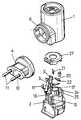
도 2는 장치의 내측부에 연결되는 접촉부(contact)를 장착하기 위한 본 발명의 장치의 내측부의 사시도인데, 도시된 분해도에서 전기적 가열 저항기(electrical heating resistor)와 플러그의 두개의 핀들이 도시되어지며, 비록 플러그 몸체부는 도시되지 않았지만, 상기 핀의 내측단부는 상기에서 언급된 내측부 상에 장착된 접촉부와 만나게 된다.FIG. 2 is a perspective view of the inner part of the device of the present invention for mounting a contact connected to the inner part of the device, in the exploded view shown two pins of an electrical heating resistor and a plug are shown; Although the plug body is not shown, the inner end of the pin encounters a contact mounted on the above mentioned inner part.
도 3은 플러그는 없지만, 활성물질을 담고있는 용기의 부착과 고정을 위한 내측부의 탄성변형 가능한 바닥링(bottom ring)의 형상과, 상기 용기를 해제하도록 상기 내부 링이 압축되어지는 내부 케이스(inner casing)의 탄성 내부 영역을 나타내고 있는 본 발명에 따른 장치의 바닥부 사시도.Figure 3 shows the shape of an elastically deformable bottom ring for attachment and fixation of the container containing the active material but without the plug, and an inner case in which the inner ring is compressed to release the container. Bottom perspective view of the device according to the invention showing the elastic inner region of the casing.
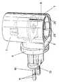
도 4a와 도 4b는 조립된 장치의 전체적인 모습과 분해도를 사시도로 나타내고 있는데, 여기서는 외부 케이스와 플러그, 그리고 가열장치의 하단부에 연결되어지고 유지되어질 수 있는 용기 내에 담겨진 활성물질을 증발시키기 위하여 가열되어져야만 하는 심지(wick)가 위치되어지는 넥(neck)이 제공되고, 접촉부를 포함하는 내측부가 도시되어진다.4A and 4B show, in perspective view, an overall view and exploded view of the assembled device, where it is heated to evaporate the active material contained in the outer casing and plug, and in a container that can be connected and maintained at the bottom of the heating device. A neck is provided in which a wick that should be placed is provided, and an inner portion including a contact is shown.
<도면의 주요부분에 대한 부호의 설명><Description of the symbols for the main parts of the drawings>
1 : 외부 케이스4 : 잭플러그1: outer case 4: jack plug
6 : 실린더 몸체부 7 : 탄성부6: cylinder body portion 7: elastic portion
14 : 브릿지15 : 경사진 탭14
20 : 가열요소21 : 부착요소20: heating element 21: attachment element
도면에서 도시된 바와 같이, 본 발명의 장치는 네가지 기본적인 부품 또는 요소와 다섯 번째 선택적인 부품으로 구성되는데, 첫 번째 부품은 실린더 형상의 일반적인 외부 케이스(external casing, 1)이며, 두 번째 부품은 상기 외부 케이스(1) 내에 장착되어지는 내측부(inner part, 2)이며, 세 번째 부품은 장치의 접촉부(contact)를 형성하는 두개의 접촉요소(contact element, 3,3')로 구성되며, 네 번째 구성요소 또는 부품은 잭 플러그(jack plug, 4)이며, 원형(circular)이며 가장자리가 편평한 형태로 된 다섯 번째 선택적인 부품(27)은 하나 또는 그 이상의 가열요소(heating element, 20)와 그리고 대응되는 부착요소(attachment element, 21)를 위하여 제공된 하우징(housing)을 위한 리드(lid)로서 사용되어진다.As shown in the figures, the device of the present invention consists of four basic parts or elements and a fifth optional part, the first part being a cylindrical external casing (1) and the second part being the An
외부 케이스(external casing, 1)와 관련하여, 바닥부(bottom)가 개방되어 있고, 측면에는 잭 플러그(jack plug)가 연결되어지는 실린더 몸체부(cylindrical body, 6)가 분기되는 돌출부(projection, 5)가 제공되어지며, 외부 케이스(1)는 바닥부가 개방된 것으로 기술되어진 단부에서 외부 케이스(1)의 실린더형 몸체의 두개의 축방향 틈새(slit, 8) 사이에서 형성된 탄성부(elastic sector, 7)를 포함하여, 아래에서 추가적으로 기술되어지는 바와 같이 상기 탄성부(7)는 증발되어지는 활성물질(active substance)을 담고 있는 용기를 해제하는 기능을 수행하게 된다.
With respect to the
실린더 몸체부(6)의 내부에는 상기 실린더 몸체부(6)의 높이보다 짧은 길이를 가진 다수의 돌출부(projection, 9)가 제공되어진다.The inside of the
잭 플러그(jack plug, 4)는 몰딩(molding)에 의해 얻어진 몸체부로 구성되며, 전원공급 플러그와 접촉하기 위한 외부영역(outer segment, 11)과 접촉요소(contact element, 3,3')와 접촉하기 위한 내측단부(inner end, 12)를 가진 핀(pin, 10)이 삽입되어 있다. 또한, 잭 플러그(4)의 몸체부는 플러그(4)의 몸체부가 외부 케이스(1)의 실린더 몸체부(6) 내부에 연결되어질 때 지지하기 위한 수단을 제공하는 또 다른 돌출부(13)를 가지고 있으며, 상기 돌출부(13)는 실린더 몸체부(6)의 돌출부(9)의 내부 단부를 통과할 때, 따라서 외부 케이스(1) 내의 플러그(4)의 지지는 축방향으로의 제거는 허용하지 않지만 회전(rotation)을 허용함으로써, 플러그(4)가 사용자가 원하는 대로 위치되어질 수 있도록 하지만, 축방향 변위는 허용하지 않고 회전만을 항상 허용하도록 한다.
The
접촉요소(contact element, 3,3')는 한쪽 단부 상에서 경사진 탭(tab, 15)이 있는 브릿지(bridge, 14) 종류가 제공되어져서, 상기 브릿지에 의해서 접촉요소(3,3')가 내측부(2) 내에 제공된 벽(16) 상에서 장착되어지도록 되며, 상기 벽(16)들이 접촉요소(3,3')의 상부 단부에서 제공되어진 브릿지(4) 내부에 위치되어, 도 2에서 명확하게 도시된 바와 같이 접촉부가 내측부(2)에 완전하게 지지되어지고 위치되어진다.
또한, 접촉요소(3,3')들은 아치형 돌출부(17,18)를 가지는데, 상기 아치형 돌출부는 잭 플러그(4)에 의해서 채택된 위치에 따라서 상기 플러그(4)의 핀(10)의 내측단부(12)와 접촉하게 되는 접촉부의 쌍을 형성하도록 하는 형상과 배열을 가지도록 되어져서, 플러그의 내측단부(inner end, 12)가 접촉요소(3,3')의 돌출부(18) 상에 안착될 때, 플러그는 수평위치를 유지한 상태에서는 가열장치로 전기를 연속적으로 공급하게 되나, 만일 플러그(4)가 상기 위치로부터 90도 회전되어진다면, 플러그(4)의 핀(11)의 내측단부(12)는 돌출부(18)와 접촉하게 되며, 전기가 계속적으로 공급되어지고, 따라서 가열장치는 플러그(4)의 두 위치, 즉 수직 및 수평위치에서 작동되어질 수도 있고, 따라서 현재 상업적으로 판매되고 있는 어떠한 형태의 소켓에도 사용된다.
The
그러나, 만일 플러그(4)가 상기에서 언급된 두개의 위치 사이의 위치에서 외부 케이스(1)에 대해서 회전되어져서 위치된다면, 즉 두개의 위치에 대해서 45도 각도에 있다면, 상기 플러그(4)의 내측단부(12)들은 돌출부(17)와 (18) 사이에 위치된 내측으로 또는 더욱 깊숙한(recessed) 평면 내에 있는 대향된 영역(opposite segment, 19)이 되고, 따라서 내측단부(12)들은 접촉요소(3,3')에 도달하지 않게 되고, 결과적으로 어떠한 형태의 스위치를 필요로 하지 않고서도 비작동 위치(deactivated position)를 얻게 된다.However, if the
자연적으로, 접촉요소(contact element, 3,3')는 하나 또는 두개의 부착요소(21)에 의해서 고정되어질 수 있는 가열요소(heating element, 20)에 연결되어지게 되며, 상응하는 연결이 수행되어지는 와이어 단부(22) 부분은 접촉요소(3,3')를 장착하기 위하여 벽(wall, 16) 내에 제공된 홈(groove, 23)에 대해서 접촉요소(3,3')의 브릿지(bridge, 14)와 탭(tab, 15)의 특수한 형상에 의해 밀어져서, 가열요소(20)의 와이어 단부(22)의 상기 끝부분들은 홈(groove) 또는 슬롯(slot) (23)에 대응되는 위치 내에서 접혀지고 곧게 펴지도록 된다.Naturally, the
내측부(inner part, 2)와 관련하여, 앞서 기술된 특징 이외에도 활성물질(active substance)을 담는 용기(vessel)의 심지(wick)를 위치시키기 위하여 대응되는 넥(neck, 24)이 제공되어지며, 내측부(2)의 상측단부 또는 내측 상에 위치된 핀(pin, 25)에 의해서 외부 케이스(external casing, 1)의 안쪽으로 고정되어 유닛의 바닥부에 장착되어져야만 하고, 외부 케이스(1)의 내부에 고정되어져서, 유닛을 파손하지 않고서는 빠질 가능성이 없도록 결속된다.With respect to the
마지막으로, 상기 내측부(2)는 하단부에 타원형 형상의 탄성링(elastic ring, 26)이 제공되어지며, 증발되어지는 물질을 담고 있는 용기가 넥(neck)에 의해서 측면들 사이에서 유지되어지고, 용기에는 내측부(2)의 넥(24)을 통하여 위쪽으로 통과하는 심지(wick)가 자연적으로 제공되어져서, 상기 심지(wick)가 그 주위에 있는 가열요소(heating element, 20)에 의해서 가열되어져서, 모세관 작용(capillary action)에 의해서 상기에서 언급된 바와 같이 위치된 심지의 상부까지 상승된 액체 또는 물질이 증발(evaporation)되게 한다. 용기를 탄성링(26)으로부터 해제하기 위하여는, 외부 케이스(external casing, 1)의 탄성부(elastic sector, 7) 상에서 바깥쪽으로부터 안쪽으로 누르는 것으로 충분한데, 이러한 압력은 탄성부(7)의 안쪽반향으로의 변형과 관련되어지고, 따라서 탄성링(26)의 영역(segment, 26')을 밀고, 링의 측면들을 분리시키고 따라서 용기를 해제하게 된다.Finally, the
Claims (7)
Translated fromKoreanApplications Claiming Priority (1)
| Application Number | Priority Date | Filing Date | Title |
|---|---|---|---|
| PCT/ES2000/000368WO2002028442A1 (en) | 2000-10-03 | 2000-10-03 | Heater device for active substances |
Publications (2)
| Publication Number | Publication Date |
|---|---|
| KR20030045102A KR20030045102A (en) | 2003-06-09 |
| KR100554808B1true KR100554808B1 (en) | 2006-02-22 |
Family
ID=8244271
Family Applications (1)
| Application Number | Title | Priority Date | Filing Date |
|---|---|---|---|
| KR1020037004745AExpired - Fee RelatedKR100554808B1 (en) | 2000-10-03 | 2000-10-03 | Heater device for active substances |
Country Status (14)
| Country | Link |
|---|---|
| US (1) | US6850697B2 (en) |
| EP (1) | EP1332765B1 (en) |
| JP (1) | JP4638126B2 (en) |
| KR (1) | KR100554808B1 (en) |
| CN (1) | CN1213772C (en) |
| AR (1) | AR032365A1 (en) |
| AU (2) | AU1147201A (en) |
| BR (1) | BR0017349A (en) |
| CA (1) | CA2424609C (en) |
| DE (1) | DE60032646T2 (en) |
| ES (1) | ES2278638T3 (en) |
| MX (1) | MXPA03002906A (en) |
| PT (1) | PT1332765E (en) |
| WO (1) | WO2002028442A1 (en) |
Families Citing this family (34)
| Publication number | Priority date | Publication date | Assignee | Title |
|---|---|---|---|---|
| US20050195598A1 (en)* | 2003-02-07 | 2005-09-08 | Dancs Imre J. | Projecting light and images from a device |
| JP2005525897A (en) | 2002-05-13 | 2005-09-02 | エス.シー. ジョンソン アンド サン、インコーポレイテッド | Harmonious fragrance, light and sound generation |
| AU2004212459B2 (en) | 2003-02-07 | 2010-03-11 | S.C. Johnson & Son, Inc. | Diffuser with light emitting diode nightlight |
| USD507636S1 (en)* | 2004-01-27 | 2005-07-19 | Bath & Body Works, Inc. | Electric aromatherapy diffuser |
| US6996335B2 (en)* | 2004-02-12 | 2006-02-07 | S.C. Johnson & Son, Inc. | Electrical evaporator with ratcheting wick adjuster |
| USD508557S1 (en) | 2004-02-13 | 2005-08-16 | S. C. Johnson & Son, Inc. | Faceplate for volatile actives dispenser |
| USD540931S1 (en)* | 2004-03-04 | 2007-04-17 | Reckitt Benckiser (Uk) Limited | Emanator device |
| US7097161B2 (en)* | 2004-05-14 | 2006-08-29 | Chii Moon Liou | Electrical air freshener device |
| USD532092S1 (en) | 2004-06-16 | 2006-11-14 | S. C. Johnson & Son, Inc. | Housing for volatile dispenser |
| US6968124B1 (en) | 2004-06-25 | 2005-11-22 | S. C. Johnson & Son, Inc. | Electric liquid volatile dispenser |
| USD532094S1 (en)* | 2004-08-25 | 2006-11-14 | Henkel Kommanditgesellschaft Auf Aktien (Henkel Kga) | Air freshener |
| USD567918S1 (en) | 2005-02-25 | 2008-04-29 | Henkel Kommanditgesellschaft Auf Aktien | Air freshener |
| US7281811B2 (en) | 2005-03-31 | 2007-10-16 | S. C. Johnson & Son, Inc. | Multi-clarity lenses |
| US7643734B2 (en) | 2005-03-31 | 2010-01-05 | S.C. Johnson & Son, Inc. | Bottle eject mechanism |
| US7589340B2 (en) | 2005-03-31 | 2009-09-15 | S.C. Johnson & Son, Inc. | System for detecting a container or contents of the container |
| USD541922S1 (en) | 2005-03-31 | 2007-05-01 | S.C. Johnson & Son, Inc. | Diffuser |
| USD542400S1 (en) | 2005-03-31 | 2007-05-08 | S.C. Johnson & Son, Inc. | Diffuser |
| USD539407S1 (en)* | 2005-04-01 | 2007-03-27 | Zobele Holding S.P.A. | Diffuser device for deodorants |
| EP1714662B1 (en)* | 2005-04-19 | 2009-09-23 | Zobele Holding S.P.A. | Plug and heating element assembly for a diffusing device for volatile substances |
| USD544950S1 (en)* | 2005-09-15 | 2007-06-19 | Zobele Holding S.P.A. | Diffusing evaporator |
| USD544592S1 (en)* | 2005-12-09 | 2007-06-12 | Zobele Espana S.A. | Diffusing evaporator for active substances |
| USD551750S1 (en) | 2006-06-07 | 2007-09-25 | S.C. Johnson & Son, Inc. | Diffuser |
| ES2328315B1 (en)* | 2007-03-02 | 2010-09-15 | Zobele España, S.A. | MODULE FOR THE MANUFACTURE OF ELECTRIC EVAPORATORS OF VOLATILE SUBSTANCES. |
| DE102007017932A1 (en)* | 2007-04-13 | 2008-10-23 | Miele & Cie. Kg | Steam generator for a household appliance that can be heated by means of a heat accumulator |
| US7840123B2 (en)* | 2007-06-21 | 2010-11-23 | S.C. Johnson & Son, Inc. | Diffusion device |
| USD659818S1 (en) | 2011-04-28 | 2012-05-15 | S.C. Johnson & Son, Inc. | Dispenser |
| USD661790S1 (en) | 2011-07-25 | 2012-06-12 | Majerowski Amelia H | Cover for a dispenser |
| US8821171B2 (en) | 2011-09-22 | 2014-09-02 | S.C. Johnson & Son, Inc. | Rotatable plug assembly and housing for a volatile material dispenser |
| US8858236B2 (en) | 2011-10-28 | 2014-10-14 | S.C. Johnson & Son, Inc. | Rotatable plug assembly and method of reducing strain in a wire |
| USD732654S1 (en)* | 2014-11-20 | 2015-06-23 | Ming Jen Hsiao | Plug-in scent warmer |
| USD729924S1 (en)* | 2014-11-20 | 2015-05-19 | Ming Jen Hsiao | Plug-in scent warmer |
| CN104544575B (en)* | 2015-01-20 | 2021-01-29 | 卓尔悦欧洲控股有限公司 | Atomizer and electronic cigarette thereof |
| USD776800S1 (en)* | 2015-04-27 | 2017-01-17 | Reckitt Benckiser (Brands) Limited | Volatile substance dispenser |
| US11925732B2 (en)* | 2018-09-26 | 2024-03-12 | The Yankee Candle Company, Inc. | Device for volatilizing compounds with a selectively adjustable heat source |
Family Cites Families (11)
| Publication number | Priority date | Publication date | Assignee | Title |
|---|---|---|---|---|
| JPS627098Y2 (en)* | 1979-09-21 | 1987-02-18 | ||
| US4874924A (en)* | 1987-04-21 | 1989-10-17 | Tdk Corporation | PTC heating device |
| JPH0718294Y2 (en)* | 1988-02-10 | 1995-05-01 | アース製薬株式会社 | Heating evaporator |
| ES1004915Y (en)* | 1988-03-04 | 1989-04-01 | Cooper-Zeltia, S.A. | DEVICE FOR VAPORIZING THERMALLY VAPORIZABLE SUBSTANCES. |
| ES1005422Y (en)* | 1988-03-29 | 1990-07-01 | Productos Cruz Verde S.A. | PERFECTED APPARATUS FOR THE EVAPORATION OF VOLATILE PRODUCTS. |
| ES1009203Y (en)* | 1989-02-24 | 1990-01-16 | Benckiser, S.A. | PERFECTED AIR FRESHENER DEVICE. |
| EP0696457B1 (en)* | 1994-08-03 | 1999-02-10 | Steinel GmbH & Co. KG | Electric vaporizer for active substances |
| US5647053A (en)* | 1995-10-11 | 1997-07-08 | S. C. Johnson & Son, Inc. | Vapor dipensing device |
| AU6975798A (en)* | 1997-04-14 | 1998-11-11 | S.C. Johnson & Son, Inc. | Liquid air freshener dispenser device with disposable wicking cartridge unit |
| ES2137111B1 (en)* | 1997-06-24 | 2000-09-16 | Dbk Espana Sa | EVAPORATOR DEVICE FOR VOLATILE PRODUCTS WITH VARIABLE EVAPORATION INTENSITY. |
| IT1298812B1 (en)* | 1998-03-26 | 2000-02-02 | Zobele Ind Chim | VAPORIZER OF INSECTICIDES OR PERFUMES IN LIQUID FORMULATIONS WITH ELECTRIC HEATING ELEMENT ATTACHED TO THE SWIVEL PLUG |
- 2000
- 2000-10-03ESES00972910Tpatent/ES2278638T3/ennot_activeExpired - Lifetime
- 2000-10-03WOPCT/ES2000/000368patent/WO2002028442A1/enactiveIP Right Grant
- 2000-10-03CNCNB008200106Apatent/CN1213772C/ennot_activeExpired - Fee Related
- 2000-10-03MXMXPA03002906Apatent/MXPA03002906A/enactiveIP Right Grant
- 2000-10-03DEDE60032646Tpatent/DE60032646T2/ennot_activeExpired - Lifetime
- 2000-10-03PTPT00972910Tpatent/PT1332765E/enunknown
- 2000-10-03CACA002424609Apatent/CA2424609C/ennot_activeExpired - Fee Related
- 2000-10-03BRBR0017349-5Apatent/BR0017349A/ennot_activeApplication Discontinuation
- 2000-10-03AUAU1147201Apatent/AU1147201A/enactivePending
- 2000-10-03JPJP2002532266Apatent/JP4638126B2/ennot_activeExpired - Fee Related
- 2000-10-03EPEP00972910Apatent/EP1332765B1/ennot_activeExpired - Lifetime
- 2000-10-03KRKR1020037004745Apatent/KR100554808B1/ennot_activeExpired - Fee Related
- 2000-10-03AUAU2001211472Apatent/AU2001211472B9/ennot_activeCeased
- 2001
- 2001-09-25ARARP010104518Apatent/AR032365A1/enactiveIP Right Grant
- 2003
- 2003-04-02USUS10/406,641patent/US6850697B2/ennot_activeExpired - Lifetime
Also Published As
| Publication number | Publication date |
|---|---|
| MXPA03002906A (en) | 2003-06-24 |
| PT1332765E (en) | 2007-03-30 |
| BR0017349A (en) | 2004-01-13 |
| EP1332765B1 (en) | 2006-12-27 |
| WO2002028442A1 (en) | 2002-04-11 |
| CA2424609C (en) | 2008-08-26 |
| CN1457262A (en) | 2003-11-19 |
| US6850697B2 (en) | 2005-02-01 |
| JP4638126B2 (en) | 2011-02-23 |
| DE60032646T2 (en) | 2007-11-15 |
| CA2424609A1 (en) | 2003-04-02 |
| AU2001211472B9 (en) | 2006-11-02 |
| US20030231876A1 (en) | 2003-12-18 |
| WO2002028442A9 (en) | 2002-10-03 |
| CN1213772C (en) | 2005-08-10 |
| AU2001211472B2 (en) | 2006-07-06 |
| KR20030045102A (en) | 2003-06-09 |
| ES2278638T3 (en) | 2007-08-16 |
| AU1147201A (en) | 2002-04-15 |
| AR032365A1 (en) | 2003-11-05 |
| DE60032646D1 (en) | 2007-02-08 |
| JP2004515226A (en) | 2004-05-27 |
| EP1332765A1 (en) | 2003-08-06 |
Similar Documents
| Publication | Publication Date | Title |
|---|---|---|
| KR100554808B1 (en) | Heater device for active substances | |
| US4804821A (en) | Aroma diffuser assembly | |
| EP1701614B1 (en) | Electric liquid volatile dispenser | |
| US6478440B1 (en) | Night light air freshener | |
| US4731520A (en) | Aroma diffuser apparatus | |
| US5574821A (en) | Plug in volatile substance dispenser and method for dispensing volatiles | |
| US20040033066A1 (en) | Methods and apparatus for dual-outlet vapor dispenser | |
| PL198536B1 (en) | Electrical device for evaporating a volatile liquid | |
| EP1249163A1 (en) | Thermal vaporizer for a liquid formulation comprising a volatile active | |
| JP2006500979A5 (en) | ||
| AU2001243552A1 (en) | Night light air freshener | |
| JP4739648B2 (en) | Heating device for vaporizing active substances | |
| WO1998057674A1 (en) | New electric heating device with emission of active substances | |
| KR20030020884A (en) | Actives dispenser with offset electrical plug | |
| US20050286876A1 (en) | Volatizer with integrated thermal cutoff | |
| WO2012149103A1 (en) | Rotating electrical plug assembly for volatile material dispenser | |
| JPH0425978Y2 (en) | ||
| ZA200302693B (en) | Heater device for active substances. | |
| JPH09308422A (en) | Heating evaporator |
Legal Events
| Date | Code | Title | Description |
|---|---|---|---|
| PA0105 | International application | St.27 status event code:A-0-1-A10-A15-nap-PA0105 | |
| P11-X000 | Amendment of application requested | St.27 status event code:A-2-2-P10-P11-nap-X000 | |
| P13-X000 | Application amended | St.27 status event code:A-2-2-P10-P13-nap-X000 | |
| PG1501 | Laying open of application | St.27 status event code:A-1-1-Q10-Q12-nap-PG1501 | |
| A201 | Request for examination | ||
| PA0201 | Request for examination | St.27 status event code:A-1-2-D10-D11-exm-PA0201 | |
| E902 | Notification of reason for refusal | ||
| PE0902 | Notice of grounds for rejection | St.27 status event code:A-1-2-D10-D21-exm-PE0902 | |
| T11-X000 | Administrative time limit extension requested | St.27 status event code:U-3-3-T10-T11-oth-X000 | |
| T11-X000 | Administrative time limit extension requested | St.27 status event code:U-3-3-T10-T11-oth-X000 | |
| R17-X000 | Change to representative recorded | St.27 status event code:A-3-3-R10-R17-oth-X000 | |
| P11-X000 | Amendment of application requested | St.27 status event code:A-2-2-P10-P11-nap-X000 | |
| P13-X000 | Application amended | St.27 status event code:A-2-2-P10-P13-nap-X000 | |
| E701 | Decision to grant or registration of patent right | ||
| PE0701 | Decision of registration | St.27 status event code:A-1-2-D10-D22-exm-PE0701 | |
| PR1002 | Payment of registration fee | St.27 status event code:A-2-2-U10-U12-oth-PR1002 Fee payment year number:1 | |
| GRNT | Written decision to grant | ||
| PR0701 | Registration of establishment | St.27 status event code:A-2-4-F10-F11-exm-PR0701 | |
| PG1601 | Publication of registration | St.27 status event code:A-4-4-Q10-Q13-nap-PG1601 | |
| PR1001 | Payment of annual fee | St.27 status event code:A-4-4-U10-U11-oth-PR1001 Fee payment year number:4 | |
| FPAY | Annual fee payment | Payment date:20100217 Year of fee payment:5 | |
| PR1001 | Payment of annual fee | St.27 status event code:A-4-4-U10-U11-oth-PR1001 Fee payment year number:5 | |
| LAPS | Lapse due to unpaid annual fee | ||
| PC1903 | Unpaid annual fee | St.27 status event code:A-4-4-U10-U13-oth-PC1903 Not in force date:20110217 Payment event data comment text:Termination Category : DEFAULT_OF_REGISTRATION_FEE | |
| PC1903 | Unpaid annual fee | St.27 status event code:N-4-6-H10-H13-oth-PC1903 Ip right cessation event data comment text:Termination Category : DEFAULT_OF_REGISTRATION_FEE Not in force date:20110217 |