KR100554376B1 - Vacuum breaker using permanent magnet actuator - Google Patents
Vacuum breaker using permanent magnet actuatorDownload PDFInfo
- Publication number
- KR100554376B1 KR100554376B1KR1020030096689AKR20030096689AKR100554376B1KR 100554376 B1KR100554376 B1KR 100554376B1KR 1020030096689 AKR1020030096689 AKR 1020030096689AKR 20030096689 AKR20030096689 AKR 20030096689AKR 100554376 B1KR100554376 B1KR 100554376B1
- Authority
- KR
- South Korea
- Prior art keywords
- lever
- permanent magnet
- coupled
- mover
- opening
- Prior art date
- Legal status (The legal status is an assumption and is not a legal conclusion. Google has not performed a legal analysis and makes no representation as to the accuracy of the status listed.)
- Expired - Fee Related
Links
Images


Classifications
- H—ELECTRICITY
- H01—ELECTRIC ELEMENTS
- H01H—ELECTRIC SWITCHES; RELAYS; SELECTORS; EMERGENCY PROTECTIVE DEVICES
- H01H33/00—High-tension or heavy-current switches with arc-extinguishing or arc-preventing means
- H01H33/60—Switches wherein the means for extinguishing or preventing the arc do not include separate means for obtaining or increasing flow of arc-extinguishing fluid
- H01H33/66—Vacuum switches
- H01H33/666—Operating arrangements
- H01H2033/6667—Details concerning lever type driving rod arrangements
Landscapes
- Driving Mechanisms And Operating Circuits Of Arc-Extinguishing High-Tension Switches (AREA)
Abstract
Translated fromKoreanDescription
Translated fromKorean도 1은 종래의 스프링을 이용한 진공 차단기를 도시한 주요부 사시도1 is a perspective view of an essential part showing a vacuum circuit breaker using a conventional spring
도 2a 및 도 2b는 본 발명에 따른 영구자석형 조작기를 이용한 진공 차단기의 정면도 및 단면도2A and 2B are a front view and a cross-sectional view of a vacuum circuit breaker using a permanent magnet actuator according to the present invention.
도 3a는 본 발명에 따른 영구자석형 조작기의 트립 상태를 도시한 설명도Figure 3a is an explanatory diagram showing a trip state of the permanent magnet actuator according to the present invention
도 3b는 도 3a의 투입 직전 상태를 도시한 설명도3B is an explanatory diagram showing a state immediately before the input of FIG. 3A;
도 3c는 도 3a의 투입 상태를 도시한 설명도3C is an explanatory diagram showing an input state of FIG. 3A
< 도면의 주요 부분에 대한 부호의 설명 ><Description of Symbols for Main Parts of Drawings>
10; 영구자석형 조작기11; 철심10;
12; 가동자13; 영구자석12; Mover 13; Permanent magnet
14; 트립 코일15; 투입 코일14;
20; 드라이브 로드30; 블록20;
40; 개폐축41; 제1레버40; Opening and
42; 제2레버50; 푸시로드42;
60; 진공 차단부60; Vacuum interrupter
본 발명은 영구자석형 조작기를 이용한 진공 차단기에 관한 것으로서, 보다 상세히는 부품수를 대폭 줄여 소형화를 가능하게 하고, 연결 구조를 단순화함으로써, 동작 신뢰성 및 조립성을 향상시킬 수 있는 영구자석형 조작기를 이용한 진공 차단기에 관한 것이다.The present invention relates to a vacuum circuit breaker using a permanent magnet actuator, and more particularly, to reduce the number of parts to enable a miniaturization, and to simplify the connection structure, the permanent magnet actuator that can improve the operation reliability and assembly It relates to a vacuum circuit breaker used.
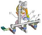
도 1을 참조하면, 종래 스프링을 이용한 진공 차단기의 주요부 사시도가 도시되어 있다.1, there is shown a perspective view of an essential part of a conventional vacuum circuit breaker using a spring.
도시된 바와 같이 종래의 진공 차단기는 수직 방향으로 설치된 스프링(1')과, 상기 스프링(1')과 대략 수평하게 설치된 다수의 링크(2')와, 상기 링크(2')의 하단에 접촉 및 분리 가능하게 설치된 레버(3')와, 상기 레버(3')의 상,하 이동에 의해 소정 방향으로 회전 가능하도록 상기 스프링(1')에 대략 수직 방향으로 설치된 개폐축(4')으로 이루어져 있다. 여기서, 진공 개폐부(미도시)는 상기 개폐축(4')에 레버로 연결되어 트립 및 투입이 가능하게 되어 있다.As shown, a conventional vacuum circuit breaker contacts a spring 1 'installed in a vertical direction, a plurality of links 2' installed substantially horizontally with the spring 1 ', and a lower end of the link 2'. And a lever 3 'detachably provided and an opening and closing shaft 4' installed in a direction substantially perpendicular to the spring 1 'so as to be rotatable in a predetermined direction by the up and down movement of the
이러한 종래의 진공 차단기는 트립 상태에서 투입 상태로 동작이 일어나면, 먼저 축세된 스프링(1')의 반발력에 의해 링크(2')가 하부로 이동하게 된다. 그러면, 상기 링크(2')의 이동에 의해 레버(3')도 아래 방향으로 이동하게 된다. 또한, 상기 레버(3')의 이동에 의해 개폐축(4')이 소정 방향으로 회전하게 되고, 이에 따라 도시되지 않은 진공 개폐부가 투입되게 된다.When the conventional vacuum circuit breaker operates from the tripped state to the closed state, the link 2 'is moved downward by the repulsive force of the spring 1' which is first stored. Then, the lever 3 'is also moved downward by the movement of the link 2'. In addition, the opening and closing shaft 4 'is rotated in a predetermined direction by the movement of the lever 3', and thus the vacuum opening and closing part (not shown) is introduced.
그러나, 이러한 종래의 진공 차단기는 스프링에 축세되어 있는 힘을 개폐축 에 전달하기 위한 구조가 매우 복잡하고 부품수가 많음으로써 동작의 신뢰성이 저하되는 문제가 있다.However, such a conventional vacuum circuit breaker has a problem that the reliability of the operation is deteriorated because the structure for transmitting the force stored in the spring to the open / close shaft is very complicated and the number of parts is large.
또한, 부품수가 많아서 장치의 소형화가 어렵고 더욱이 조립이 어려워 유지 보수가 매우 힘든 문제가 있다.In addition, due to the large number of parts, it is difficult to miniaturize the device, and furthermore, it is difficult to assemble, which is a very difficult maintenance.
따라서, 본 발명은 상기 문제점을 해결하기 위하여 이루어진 것으로, 본 발명의 목적은 부품수를 대폭 줄여 소형화를 가능하게 하고, 연결 구조를 단순화함으로써, 동작 신뢰성 및 조립성을 향상시킬 수 있는 영구자석형 조작기를 이용한 진공 차단기를 제공하는데 있다.Accordingly, the present invention has been made to solve the above problems, and an object of the present invention is to reduce the number of parts significantly to enable miniaturization, and to simplify the connection structure, the permanent magnet actuator that can improve the operation reliability and assembly To provide a vacuum circuit breaker using.
상기 목적을 달성하기 위한 본 발명에 의한 진공 차단기는, 내부에 일정 공간부를 가지며 적층되어 있는 다수의 철심과, 상기 철심의 공간부에 상, 항 방향으로 이동 가능하게 설치된 가동자와, 상기 가동자의 하단에 결합되어 상, 하 방향으로 일정 거리 이동 가능한 드라이브 로드와, 상기 가동자의 외주연에 결합된 다수의 영구자석과, 상기 가동자의 외주연으로서 상기 영구자석의 상부에 다수회 권취된 트립 코일과, 상기 가동자의 외주연으로서 상기 영구자석의 하부에 다수회 권취된 투입 코일을 구비하는 영구자석형 조작기; 상기 영구자석형 조작기의 드라이브 로드 하단에 설치되어, 상기 드라이브 로드의 상, 하 방향 동력을 전달하는 블록; 상기 블록과 일단부가 결합되어 상기 블록의 상, 하 방향 동력에 따라 회동가능한 제 1 레버; 상기 제 1 레버의 타단부와 결합되어 상기 제 1 레버의 회동방향과 동일한 방향으로 회전가능한 개폐축; 상기 개폐축에 결합되어, 상기 개폐축의 회전 방향에 따라 동일 방향으로 회전가능한 제 2 레버; 상기 제 2 레버의 회전에 따라 온, 오프되는 진공 차단부; 및 상기 진공 차단부와 제 2 레버 사이에 설치되어 상기 제 2 레버의 회동력을 상기 진공 차단부에 상, 하 방향의 동력으로 전달하는 푸시로드;를 포함한다.
상기와 같이 하여 본 발명에 의한 영구자석형 조작기를 이용한 진공 차단기는 영구자석형 조작기에 의해 개폐축이 소정 방향으로 회전함으로써, 부품수가 종래에 비해 대폭 줄어들고 또한 이에 따라 장치의 소형화가 가능하게 된다.A vacuum circuit breaker according to the present invention for achieving the above object is a plurality of iron cores having a predetermined space portion therein, a movable part installed in the space portion of the iron core so as to be movable in the up and down directions, A drive rod coupled to a lower end and movable at a predetermined distance in the up and down directions, a plurality of permanent magnets coupled to the outer circumference of the mover, and a trip coil wound multiple times on an upper portion of the permanent magnet as the outer circumference of the mover; And a permanent magnet actuator having an injection coil wound around the bottom of the permanent magnet as the outer circumference of the mover. A block installed at a lower end of a drive rod of the permanent magnet actuator to transfer power up and down of the drive rod; A first lever coupled to one end of the block and rotatable according to up and down power of the block; An opening and closing shaft coupled to the other end of the first lever and rotatable in the same direction as the rotation direction of the first lever; A second lever coupled to the opening / closing shaft and rotatable in the same direction according to the rotation direction of the opening / closing shaft; A vacuum interrupter turned on and off in response to the rotation of the second lever; And a push rod installed between the vacuum interrupter and the second lever to transfer the rotational force of the second lever to the vacuum interrupter with power in up and down directions.
As described above, the vacuum circuit breaker using the permanent magnet actuator according to the present invention is rotated in a predetermined direction by the permanent magnet actuator, so that the number of parts is greatly reduced as compared with the conventional one, and accordingly the apparatus can be miniaturized.
삭제delete
삭제delete
삭제delete
삭제delete
삭제delete
더불어, 진공 차단부를 온,오프시키기 위한 연결 구조가 단순함으로써, 동작의 신뢰성이 높아지고 또한 조립성도 향상된다.In addition, since the connection structure for turning on and off the vacuum interrupter is simple, the operation reliability is increased and the assemblability is also improved.
이하, 본 발명이 속하는 기술 분야에서 통상의 지식을 가진 자가 본 발명을 용이하게 실시할 수 있을 정도로 본 발명의 바람직한 실시예를 첨부된 도면을 참조하여 상세하게 설명하면 다음과 같다.Hereinafter, preferred embodiments of the present invention will be described in detail with reference to the accompanying drawings such that those skilled in the art may easily implement the present invention.
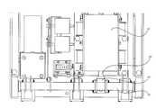
도 2a를 참조하면, 본 발명에 따른 영구자석형 조작기를 이용한 진공 차단기 의 정면도가 도시되어 있고, 도 2b를 참조하면, 그 단면도가 도시되어 있다. 여기서, 도 2b는 트립 상태를 도시한 것이다.Referring to FIG. 2A, a front view of a vacuum circuit breaker using a permanent magnet actuator according to the present invention is shown, and referring to FIG. 2B, a cross-sectional view thereof is shown. 2B illustrates a trip state.
도시된 바와 같이 본 발명에 의한 진공 차단기는 상,하로 일정 거리 이동 가능한 드라이브 로드(20)를 갖는 영구자석형 조작기(10)와, 상기 드라이브 로드(20)의 힘을 전달하는 블록(30)과, 상기 블록(30)의 힘에 의해 소정 방향으로 회전하는 개폐축(40)과, 상기 개폐축(40)의 힘을 상부로 전달하는 푸시로드(50)와, 상기 푸시로드(50)에 의해 온,오프되는 진공 차단부(60)로 이루어져 있다.As shown, the vacuum circuit breaker according to the present invention includes a
먼저 상기 영구자석형 조작기(10)는 내부에 일정 공간부를 가지며 적층되어 있는 다수의 철심(11)이 구비되어 있다. 또한, 상기 철심(11)의 공간부에는 상,하 방향으로 이동 가능하게 설치된 가동자(12)가 구비되어 있다. 물론, 상기 가동자(12)의 하단에는 상술한 드라이브 로드(20)가 결합되어 있다. 또한, 상기 가동자(12)의 외주연에는 다수의 영구자석(13)이 결합되어 있다. 더불어, 상기 가동자(12)의 외주연으로서 상기 영구자석(13)의 상부에는 트립 코일(14)이 다수회 권취되어 있다. 마지막으로, 상기 가동자(12)의 외주연으로서 상기 영구자석(13)의 하부에는 투입 코일(15)이 다수회 권취되어 있다. 물론, 상기 트립 코일(14) 및 투입 코일(15)도 상기 철심(11)의 공간부에 위치되어 있다.First, the
상기 블록(30)은 상기 영구자석형 조작기(10)의 드라이브 로드(20) 하단에 설치되어, 상기 드라이브 로드(20)의 힘을 전달할 수 있도록 되어 있다.The
상기 개폐축(40)은 상기 블록(30)의 하부인 동시에 측부에 설치되어, 상기 블록(30)의 상,하 이동에 따라 일정 방향으로 회전 가능하게 설치되어 있다. 더불 어, 상기 개폐축(40)은 일측에 상기 블록(30)과 결합되도록 일정 길이 연장된 제1레버(41)가 구비되어 있다. 또한, 상기 개폐축(40)은 타측에 상기 진공 차단부(60)를 온,오프 하도록 일정 길이 연장된 제2레버(42)가 구비되어 있다.The opening and
상기 푸시로드(50)는 상기 진공 차단부(60)와 상기 제2레버(42) 사이에 설치되어 있다. 따라서, 상기 푸시로드(50)는 상기 제2레버(42)가 상승하면 함께 상승하고, 상기 제2레버(42)가 하강하면 함께 하강한다.The
마지막으로, 상기 진공 차단부(60)는 상기 푸시로드(50)의 상단에 설치되어 있으며, 이는 상기 푸시로드(50)가 상승하면 온되고, 하강하면 오프되도록 되어 있다.Finally, the
도3a를 참조하면, 본 발명에 따른 영구자석형 조작기의 트립 상태가 도시되어 있고, 도 3b를 참조하면, 투입 직전 상태가 도시되어 있으며, 도 3c를 참조하면, 투입 상태가 도시되어 있다. 여기서는 이러한 도 3a 내지 도3c, 그리고 상술한 도 2b를 참조하여 그 작동을 설명하기로 한다. 또한, 도면중 도2b는 트립 상태이다.Referring to FIG. 3A, a trip state of the permanent magnet actuator according to the present invention is illustrated, and referring to FIG. 3B, a state immediately before closing is illustrated, and referring to FIG. 3C, a closing state is illustrated. Herein, the operation thereof will be described with reference to FIGS. 3A to 3C and FIG. 2B. 2B is a tripping state in the figure.
먼저 진공 차단기의 트립 상태를 설명한다.First, the trip state of the vacuum breaker will be described.
트립 상태에서는 영구자석형 조작기(10)의 트립 코일(14)에 전원이 인가된다(물론, 투입 코일(15)에는 전원이 인가되지 않는다). 그러면, 상기 트립 코일(14) 주변에 강력한 자기장이 형성된다. 또한, 상기 트립 코일(14)의 자기장과 영구자석(13)의 자기장은 상호 인력이 발생됨으로써, 결국 상기 영구자석(13)에 결합된 가동자(12)는 상부로 일정 거리 상승하게 된다. 물론, 상기 영구자석(13)의 극성은 상기 트립 코일(14)의 자기장과 인력이 발생하도록 가동자(12)에 결합되어 있기 때문에, 이같은 동작이 가능하다.In the trip state, power is applied to the
위와 같이 가동자(12)가 상부로 일정 거리 이동하게 되면, 이것의 하단에 결합된 드라이브 로드(20)도 상부로 이동한다. 그러면, 상기 드라이브 로드(20)에 결합된 블록(30)도 상부로 이동하고, 이에 따라 개폐축(40)에 결합된 제1레버(41)도 상승하게 된다.When the
결국 상기 개폐축(40)은 도 2b에서 반시계 방향으로 회전한다.As a result, the opening and closing
그러면, 상기 개폐축(40)에 결합된 제2레버(42)의 끝단이 하강하게 되고, 이에 따라 푸시로드(50)도 하강한다.Then, the end of the
따라서, 상기 푸시로드(50)의 하강에 따라 진공 차단부(60)가 오프된다.Therefore, the
다음으로, 진공 차단기의 투입 상태를 설명한다.Next, the input state of the vacuum circuit breaker will be described.
투입 상태에서는 영구자석형 조작기(10)의 투입 코일(15)에 전원이 인가된다(물론, 트립 코일(14)에는 전원이 인가되지 않는다). 그러면, 상기 투입 코일(15) 주변에 강력한 자기장이 형성된다. 또한, 상기 투입 코일(15)의 자기장과 영구자석(13)의 자기장은 상호 인력이 발생됨으로써, 결국 상기 영구자석(13)에 결합된 가동자(12)는 하부로 일정 거리 하강하게 된다. 물론, 상기 영구자석(13)의 극성은 상기 투입 코일(15)의 자기장과 인력이 발생하도록 가동자(12)에 결합되어 있기 때문에, 이같은 동작이 가능하다.In the closing state, power is applied to the closing
위와 같이 가동자(12)가 하부로 일정 거리 이동하게 되면, 이것의 하단에 결합된 드라이브 로드(20)도 하부로 이동한다. 그러면, 상기 드라이브 로드(20)에 결 합된 블록(30)도 하부로 이동하고, 이에 따라 개폐축(40)에 결합된 제1레버(41)도 하강하게 된다.When the
결국 상기 개폐축(40)은 도 2b에서 시계 방향으로 회전한다.As a result, the opening and closing
그러면, 상기 개폐축(40)에 결합된 제2레버(42)의 끝단이 상승하게 되고, 이에 따라 푸시로드(50)도 상승한다.Then, the end of the
따라서, 상기 푸시로드(50)의 상승에 따라 진공 차단부(60)가 온된다.Therefore, the
이상에서 설명한 것은 본 발명에 따른 영구자석형 조작기를 이용한 진공 차단기를 실시하기 위한 하나의 실시예에 불과한 것으로서, 본 발명은 상기한 실시예에 한정되지 않고, 이하의 특허청구범위에서 청구하는 바와 같이 본 발명의 요지를 벗어남이 없이 당해 발명이 속하는 분야에서 통상의 지식을 가진 자라면 누구든지 다양한 변경 실시가 가능한 범위까지 본 발명의 기술적 정신이 있다고 할 것이다.What has been described above is just one embodiment for implementing a vacuum circuit breaker using a permanent magnet actuator according to the present invention, the present invention is not limited to the above embodiment, as claimed in the claims below Without departing from the gist of the present invention, anyone of ordinary skill in the art will have the technical spirit of the present invention to the extent that various modifications can be made.
상술한 바와 같이, 본 발명에 따른 영구자석형 조작기를 이용한 진공 차단기는 영구자석형 조작기에 의해 개폐축이 소정 방향으로 회전함으로써, 부품수가 종래에 비해 대폭 줄어들고 또한 이에 따라 장치의 소형화가 가능한 효과가 있다.As described above, the vacuum circuit breaker using the permanent magnet actuator according to the present invention is rotated in a predetermined direction by the permanent magnet actuator, the number of parts is significantly reduced compared to the conventional, and accordingly the device can be miniaturized have.
더불어, 진공 차단부를 온,오프시키기 위한 연결 구조가 단순함으로써, 동작의 신뢰성이 높아지고 또한 조립성도 향상되는 효과가 있다.In addition, since the connection structure for turning on and off the vacuum interrupter is simple, the operation reliability is increased and the assemblability is also improved.
Claims (5)
Translated fromKoreanPriority Applications (1)
| Application Number | Priority Date | Filing Date | Title |
|---|---|---|---|
| KR1020030096689AKR100554376B1 (en) | 2003-12-24 | 2003-12-24 | Vacuum breaker using permanent magnet actuator |
Applications Claiming Priority (1)
| Application Number | Priority Date | Filing Date | Title |
|---|---|---|---|
| KR1020030096689AKR100554376B1 (en) | 2003-12-24 | 2003-12-24 | Vacuum breaker using permanent magnet actuator |
Publications (2)
| Publication Number | Publication Date |
|---|---|
| KR20050065798A KR20050065798A (en) | 2005-06-30 |
| KR100554376B1true KR100554376B1 (en) | 2006-02-22 |
Family
ID=37256951
Family Applications (1)
| Application Number | Title | Priority Date | Filing Date |
|---|---|---|---|
| KR1020030096689AExpired - Fee RelatedKR100554376B1 (en) | 2003-12-24 | 2003-12-24 | Vacuum breaker using permanent magnet actuator |
Country Status (1)
| Country | Link |
|---|---|
| KR (1) | KR100554376B1 (en) |
Families Citing this family (7)
| Publication number | Priority date | Publication date | Assignee | Title |
|---|---|---|---|---|
| KR100718927B1 (en)* | 2005-05-19 | 2007-05-17 | (주)에마텍 | Manipulator using electromagnetic force and breaker using the same |
| KR100909424B1 (en)* | 2007-08-08 | 2009-07-24 | 엘에스산전 주식회사 | Permanent Magnet Actuator and Circuit Breaker Equipped with the Same |
| KR101112084B1 (en)* | 2008-10-17 | 2012-02-22 | 인텍전기전자 주식회사 | Actuator using electromagnetic force |
| KR101044639B1 (en)* | 2009-10-01 | 2011-06-29 | 주식회사 비츠로테크 | Main circuit breaker for railway vehicle |
| CN109346373B (en)* | 2018-12-03 | 2024-02-09 | 福州天宇电气股份有限公司 | Three-station high-voltage vacuum circuit breaker and working method thereof |
| CN110233082B (en)* | 2019-06-27 | 2024-02-20 | 瑞熙恩电气(珠海)有限公司 | Permanent magnet vacuum circuit breaker and inflatable cabinet |
| CN117766350B (en)* | 2023-04-12 | 2025-06-10 | 常州博瑞电力自动化设备有限公司 | Quick breaking circuit breaker |
- 2003
- 2003-12-24KRKR1020030096689Apatent/KR100554376B1/ennot_activeExpired - Fee Related
Also Published As
| Publication number | Publication date |
|---|---|
| KR20050065798A (en) | 2005-06-30 |
Similar Documents
| Publication | Publication Date | Title |
|---|---|---|
| US9070517B2 (en) | Vacuum interrupter and linear disconnect switch | |
| KR101015333B1 (en) | Circuit breaker | |
| CN103650085B (en) | Drivers for switching devices | |
| KR920006061B1 (en) | Solenoid Moveable Actuator of Circuit Breaker | |
| CN111712897B (en) | Circuit breaker | |
| KR100554376B1 (en) | Vacuum breaker using permanent magnet actuator | |
| KR970000119B1 (en) | Circuit breaker with electrical disconnect means | |
| CN1203502C (en) | contact mechanism for electronic overload relays | |
| US11631564B2 (en) | Switching system, and electrical switching apparatus and switching assembly therefor | |
| US6603087B2 (en) | Switch-disconnector control unit | |
| KR100492753B1 (en) | Permanent magnetic actuator of vaccum circuit breaker | |
| CN114121562B (en) | Backup protection tripping device and electronic molded case circuit breaker | |
| JP6437356B2 (en) | Switchgear | |
| CN100349245C (en) | Antiexcitation actuator automatic reset device | |
| CN204215986U (en) | A kind of miniature circuit breaker | |
| WO2007010608A1 (en) | Breaker | |
| KR100616086B1 (en) | Circuit breaker with pressure trip device | |
| CN213816030U (en) | Operating device and circuit breaker | |
| CN1230847C (en) | Circuit breaker controls | |
| JPS6337697Y2 (en) | ||
| KR200382138Y1 (en) | A Mould Cased Circuit Breaker | |
| US10049836B1 (en) | Electrical enclosure, and switching assembly and transfer assembly therefor | |
| SU1594041A1 (en) | Electric device for operating points | |
| JP2850678B2 (en) | Main circuit switchgear | |
| KR20180020488A (en) | Circuit breaker |
Legal Events
| Date | Code | Title | Description |
|---|---|---|---|
| A201 | Request for examination | ||
| PA0109 | Patent application | St.27 status event code:A-0-1-A10-A12-nap-PA0109 | |
| PA0201 | Request for examination | St.27 status event code:A-1-2-D10-D11-exm-PA0201 | |
| R18-X000 | Changes to party contact information recorded | St.27 status event code:A-3-3-R10-R18-oth-X000 | |
| R17-X000 | Change to representative recorded | St.27 status event code:A-3-3-R10-R17-oth-X000 | |
| PG1501 | Laying open of application | St.27 status event code:A-1-1-Q10-Q12-nap-PG1501 | |
| E902 | Notification of reason for refusal | ||
| PE0902 | Notice of grounds for rejection | St.27 status event code:A-1-2-D10-D21-exm-PE0902 | |
| E13-X000 | Pre-grant limitation requested | St.27 status event code:A-2-3-E10-E13-lim-X000 | |
| P11-X000 | Amendment of application requested | St.27 status event code:A-2-2-P10-P11-nap-X000 | |
| P13-X000 | Application amended | St.27 status event code:A-2-2-P10-P13-nap-X000 | |
| E701 | Decision to grant or registration of patent right | ||
| PE0701 | Decision of registration | St.27 status event code:A-1-2-D10-D22-exm-PE0701 | |
| GRNT | Written decision to grant | ||
| PR0701 | Registration of establishment | St.27 status event code:A-2-4-F10-F11-exm-PR0701 | |
| PR1002 | Payment of registration fee | St.27 status event code:A-2-2-U10-U11-oth-PR1002 Fee payment year number:1 | |
| PG1601 | Publication of registration | St.27 status event code:A-4-4-Q10-Q13-nap-PG1601 | |
| R18-X000 | Changes to party contact information recorded | St.27 status event code:A-5-5-R10-R18-oth-X000 | |
| R18-X000 | Changes to party contact information recorded | St.27 status event code:A-5-5-R10-R18-oth-X000 | |
| R18-X000 | Changes to party contact information recorded | St.27 status event code:A-5-5-R10-R18-oth-X000 | |
| PR1001 | Payment of annual fee | St.27 status event code:A-4-4-U10-U11-oth-PR1001 Fee payment year number:4 | |
| PR1001 | Payment of annual fee | St.27 status event code:A-4-4-U10-U11-oth-PR1001 Fee payment year number:5 | |
| PN2301 | Change of applicant | St.27 status event code:A-5-5-R10-R13-asn-PN2301 St.27 status event code:A-5-5-R10-R11-asn-PN2301 | |
| PR1001 | Payment of annual fee | St.27 status event code:A-4-4-U10-U11-oth-PR1001 Fee payment year number:6 | |
| PN2301 | Change of applicant | St.27 status event code:A-5-5-R10-R13-asn-PN2301 St.27 status event code:A-5-5-R10-R11-asn-PN2301 | |
| FPAY | Annual fee payment | Payment date:20120118 Year of fee payment:7 | |
| PR1001 | Payment of annual fee | St.27 status event code:A-4-4-U10-U11-oth-PR1001 Fee payment year number:7 | |
| R18-X000 | Changes to party contact information recorded | St.27 status event code:A-5-5-R10-R18-oth-X000 | |
| FPAY | Annual fee payment | Payment date:20121221 Year of fee payment:8 | |
| PN2301 | Change of applicant | St.27 status event code:A-5-5-R10-R13-asn-PN2301 St.27 status event code:A-5-5-R10-R11-asn-PN2301 | |
| PR1001 | Payment of annual fee | St.27 status event code:A-4-4-U10-U11-oth-PR1001 Fee payment year number:8 | |
| LAPS | Lapse due to unpaid annual fee | ||
| PC1903 | Unpaid annual fee | St.27 status event code:A-4-4-U10-U13-oth-PC1903 Not in force date:20140216 Payment event data comment text:Termination Category : DEFAULT_OF_REGISTRATION_FEE | |
| PC1903 | Unpaid annual fee | St.27 status event code:N-4-6-H10-H13-oth-PC1903 Ip right cessation event data comment text:Termination Category : DEFAULT_OF_REGISTRATION_FEE Not in force date:20140216 | |
| R18-X000 | Changes to party contact information recorded | St.27 status event code:A-5-5-R10-R18-oth-X000 | |
| P22-X000 | Classification modified | St.27 status event code:A-4-4-P10-P22-nap-X000 | |
| PN2301 | Change of applicant | St.27 status event code:A-5-5-R10-R13-asn-PN2301 St.27 status event code:A-5-5-R10-R11-asn-PN2301 | |
| PN2301 | Change of applicant | St.27 status event code:A-5-5-R10-R13-asn-PN2301 St.27 status event code:A-5-5-R10-R11-asn-PN2301 | |
| R18-X000 | Changes to party contact information recorded | St.27 status event code:A-5-5-R10-R18-oth-X000 |