KR100552676B1 - Outdoor optical transmission / reception device having frequency conversion / combination function and method thereof, and frequency conversion / combination device in cable TV headend system and method thereof - Google Patents
Outdoor optical transmission / reception device having frequency conversion / combination function and method thereof, and frequency conversion / combination device in cable TV headend system and method thereofDownload PDFInfo
- Publication number
- KR100552676B1 KR100552676B1KR1020040046749AKR20040046749AKR100552676B1KR 100552676 B1KR100552676 B1KR 100552676B1KR 1020040046749 AKR1020040046749 AKR 1020040046749AKR 20040046749 AKR20040046749 AKR 20040046749AKR 100552676 B1KR100552676 B1KR 100552676B1
- Authority
- KR
- South Korea
- Prior art keywords
- signal
- band
- frequency
- downlink
- uplink
- Prior art date
- Legal status (The legal status is an assumption and is not a legal conclusion. Google has not performed a legal analysis and makes no representation as to the accuracy of the status listed.)
- Expired - Fee Related
Links
Images


Classifications
- H—ELECTRICITY
- H04—ELECTRIC COMMUNICATION TECHNIQUE
- H04H—BROADCAST COMMUNICATION
- H04H20/00—Arrangements for broadcast or for distribution combined with broadcast
- H04H20/65—Arrangements characterised by transmission systems for broadcast
- H04H20/69—Optical systems
- H—ELECTRICITY
- H04—ELECTRIC COMMUNICATION TECHNIQUE
- H04J—MULTIPLEX COMMUNICATION
- H04J14/00—Optical multiplex systems
- H04J14/02—Wavelength-division multiplex systems
- H04J14/0298—Wavelength-division multiplex systems with sub-carrier multiplexing [SCM]
- H—ELECTRICITY
- H04—ELECTRIC COMMUNICATION TECHNIQUE
- H04N—PICTORIAL COMMUNICATION, e.g. TELEVISION
- H04N21/00—Selective content distribution, e.g. interactive television or video on demand [VOD]
- H04N21/40—Client devices specifically adapted for the reception of or interaction with content, e.g. set-top-box [STB]; Operations thereof
- H04N21/43—Processing of content or additional data, e.g. demultiplexing additional data from a digital video stream; Elementary client operations, e.g. monitoring of home network or synchronising decoder's clock; Client middleware
- H04N21/44—Processing of video elementary streams, e.g. splicing a video clip retrieved from local storage with an incoming video stream or rendering scenes according to encoded video stream scene graphs
- H04N21/4402—Processing of video elementary streams, e.g. splicing a video clip retrieved from local storage with an incoming video stream or rendering scenes according to encoded video stream scene graphs involving reformatting operations of video signals for household redistribution, storage or real-time display
- H—ELECTRICITY
- H04—ELECTRIC COMMUNICATION TECHNIQUE
- H04N—PICTORIAL COMMUNICATION, e.g. TELEVISION
- H04N21/00—Selective content distribution, e.g. interactive television or video on demand [VOD]
- H04N21/60—Network structure or processes for video distribution between server and client or between remote clients; Control signalling between clients, server and network components; Transmission of management data between server and client, e.g. sending from server to client commands for recording incoming content stream; Communication details between server and client
- H04N21/61—Network physical structure; Signal processing
- H04N21/6106—Network physical structure; Signal processing specially adapted to the downstream path of the transmission network
- H04N21/6118—Network physical structure; Signal processing specially adapted to the downstream path of the transmission network involving cable transmission, e.g. using a cable modem
- H—ELECTRICITY
- H04—ELECTRIC COMMUNICATION TECHNIQUE
- H04N—PICTORIAL COMMUNICATION, e.g. TELEVISION
- H04N7/00—Television systems
- H04N7/10—Adaptations for transmission by electrical cable
- H—ELECTRICITY
- H04—ELECTRIC COMMUNICATION TECHNIQUE
- H04N—PICTORIAL COMMUNICATION, e.g. TELEVISION
- H04N7/00—Television systems
- H04N7/16—Analogue secrecy systems; Analogue subscription systems
- H04N7/173—Analogue secrecy systems; Analogue subscription systems with two-way working, e.g. subscriber sending a programme selection signal
- H04N7/17309—Transmission or handling of upstream communications
- H—ELECTRICITY
- H04—ELECTRIC COMMUNICATION TECHNIQUE
- H04N—PICTORIAL COMMUNICATION, e.g. TELEVISION
- H04N7/00—Television systems
- H04N7/22—Adaptations for optical transmission
- H—ELECTRICITY
- H04—ELECTRIC COMMUNICATION TECHNIQUE
- H04H—BROADCAST COMMUNICATION
- H04H60/00—Arrangements for broadcast applications with a direct linking to broadcast information or broadcast space-time; Broadcast-related systems
- H04H60/76—Arrangements characterised by transmission systems other than for broadcast, e.g. the Internet
- H04H60/81—Arrangements characterised by transmission systems other than for broadcast, e.g. the Internet characterised by the transmission system itself
- H04H60/93—Wired transmission systems
- H04H60/96—CATV systems
- H04H60/97—CATV systems using uplink of the CATV systems
Landscapes
- Engineering & Computer Science (AREA)
- Signal Processing (AREA)
- Multimedia (AREA)
- Computer Networks & Wireless Communication (AREA)
- Two-Way Televisions, Distribution Of Moving Picture Or The Like (AREA)
- Optical Communication System (AREA)
Abstract
Translated fromKoreanDescription
Translated fromKorean도 1 은 종래의 HFC망 기반의 디지털 CATV 전송 시스템의 구성예시도,1 is an exemplary configuration diagram of a conventional HFC network-based digital CATV transmission system;
도 2a 및 도 2b 는 본 발명에 따른 주파수 변환/결합 기능을 갖는 옥외형 광송수신 장치 및 그 방법과, 케이블TV 헤드엔드 시스템에서의 주파수 변환/결합 장치 및 그 방법에 대한 일실시예 일실시예 설명도,2A and 2B illustrate an outdoor optical transmission and reception apparatus and method thereof having a frequency conversion / combination function according to the present invention, and a frequency conversion / combination device and method thereof in a cable TV headend system. Explaining,
도 3 은 본 발명에 따른 주파수 변환/결합 기능을 갖는 옥외형 광송수신장치 (ONU)의 일실시예 구성도,3 is a configuration diagram of an embodiment of an outdoor type optical transmitting / receiving device (ONU) having a frequency converting / coupling function according to the present invention;
도 4 는 본 발명에 따른 도 3의 하향 주파수 변환 및 결합부의 일실시예 상세구성도,4 is a detailed configuration diagram of an embodiment of the downlink frequency converter and combiner of FIG. 3 according to the present invention;
도 5 는 본 발명에 따른 도 3의 상향 주파수 변환 및 결합부의 일실시예 상세구성도,5 is a detailed configuration diagram of an embodiment of the uplink frequency converter and combiner of FIG. 3 according to the present invention;
도 6 은 본 발명에 따른 도 3의 국부발진부의 일실시예 상세구성도,6 is a detailed configuration diagram of an embodiment of the local oscillator of FIG. 3 according to the present invention;
도 7 은 본 발명에 따른 도 3의 상태제어 및 감시부의 일실시예 상세구성도,7 is a detailed configuration diagram of an embodiment of the state control and monitoring unit of FIG. 3 according to the present invention;
도 8 은 본 발명에 따른 도 3의 상하향 대역분리부의 일실시예 상세구성도,8 is a detailed configuration diagram of an embodiment of the up-down band separation unit of FIG. 3 according to the present invention;
도 9 는 본 발명에 따른 도 8의 상하향 대역분리기의 일실시예 상세구성도,9 is a detailed configuration diagram of one embodiment of the up-down band separator of FIG. 8 according to the present invention;
도 10a 및 도 10b 는 본 발명에 따른 옥외형 광송수신 장치(ONU)에서의 하향/상향 주파수 변환/결합 방법에 대한 일실시예 흐름도,10A and 10B are flowcharts of an embodiment of a downlink / uplink frequency conversion / combining method in an outdoor optical transmitting / receiving device (ONU) according to the present invention;
도 11a 및 도 11b 는 본 발명에 따른 케이블 티브이 헤드엔드 시스템에서의 하향/상향 주파수 변환/결합 방법에 대한 일실시예 흐름도이다.11A and 11B are flowcharts of one embodiment of a downlink / uplink frequency conversion / combining method in a cable TV headend system according to the present invention.
* 도면의 주요 부분에 대한 부호의 설명* Explanation of symbols for the main parts of the drawings
100: 헤드엔드 시스템 200: 주파수 변환/결합 장치100: headend system 200: frequency conversion / combining device
212: 업컨버터(up-converter) 214: 주파수결합기212: up-converter 214: frequency combiner
216: 전광변환기 218: 광전변환기216: photoelectric converter 218: photoelectric converter
220: 주파수분배기 222: 다운컨버터(down-converter)220: frequency divider 222: down-converter
224: 옥외형 광송수신장치(ONU) 301: 하향 광전변환부224: outdoor type optical transmission and reception unit (ONU) 301: downlink photoelectric conversion unit
302: 하향 주파수 변환 및 결합부 303: 국부발진부302: downlink frequency converter and combiner 303: local oscillator
304: 상태제어 및 감시부 306: 상향 주파수 변환 및 결합부304: state control and monitoring unit 306: uplink frequency conversion and coupling unit
307: 상향 전광변환부307: up-light conversion unit
본 발명은, 디지털 CATV 전송 기술에 관한 것으로, 더욱 상세하게는 주파수 변환/결합 방식을 이용하여, 하향의 경우 헤드엔드 시스템에서는 「동축케이블 가용주파수대역」이상의 대역(즉, SB(Super-Band)대역)신호로 주파수 변환하여 광케이블 네트워크로 전송하고, 옥외형 광송수신장치(ONU)에서는 동축케이블로 연결된 가입자 서브셀(Sub Cell)마다 서로 다른 하향신호를 전송할 수 있으며, 한편 상향의 경우에는 다수의 동축케이블을 통하여 입력되는 상향신호들을 「동축케이블 가용주파수대역」 내의 서로 다른 채널들로 변환하여 헤드엔드로 전송할 수 있게 하는, 주파수 변환/결합 기능을 갖는 옥외형 광송수신 장치 및 그 방법과, 케이블티브이 헤드엔드 시스템에서의 주파수 변환/결합 장치 및 그 방법에 관한 것이다.The present invention relates to a digital CATV transmission technology, and more particularly, by using a frequency conversion / combination method, in a head-end system in the downward direction, a band above the "coaxial cable available frequency band" (that is, SB (Super-Band)). Band) signal is converted into frequency and transmitted to the optical cable network, and in the outdoor type optical transmitter and receiver unit (ONU), different downlink signals can be transmitted for each subscriber subcell connected with a coaxial cable. Outdoor optical transmission / reception device and method having a frequency conversion / combination function for converting uplink signals input through coaxial cable into different channels in “coaxial cable available frequency band” and transmitting them to headend, and cable A frequency converting / combining device in a TV headend system and a method thereof are provided.
도 1 은 종래의 HFC망 기반의 디지털 CATV 전송 시스템의 구성예시도이다.1 is an exemplary configuration diagram of a conventional HFC network-based digital CATV transmission system.
헤드엔드 시스템(100)은 여러 개의 셀들(121, 122, 123)과 HFC 네트워크(150)를 통해 케이블 신호를 주고 받는다.The
HFC(Hybrid Fiber Coaxial) 네트워크(150)는 광케이블 네트워크(130)와 동축케이블 네트워크(140)로 구성되며, HFC 네트워크(150)상에 옥외형 광송수신 장치(ONU: Optical Node Unit)(111, 112, 113)가 있어 광신호를 전기신호로 바꾸거나 그 반대 과정을 수행한다.The hybrid fiber coaxial (HFC)
현재, 디지털 CATV 전송 시스템에서 케이블신호를 전송할 때, 먼저 헤드엔드 시스템(100)에서는 케이블 모뎀을 사용해 신호를 변조하고 특정 주파수 대역으로 주파수 변환한 후, '다른 채널의 방송신호'(즉, 「동축케이블 가용주파수대역내 방송신호(In-Band신호)」)와 함께 결합하고 이를 전광변환기를 거쳐 광케이블 네트워 크(130)로 출력한다.Currently, when transmitting a cable signal in a digital CATV transmission system, first, the head-
이렇게 변조되어 출력된 신호는 광케이블 네트워크(130)를 거쳐 옥외형 광송수신 장치(ONU)(111, 112, 113)에 도달하게 되고, 그러면 옥외형 광송수신 장치(ONU)(111, 112, 113)는 광신호를 전기신호로 변환한 후 각각의 옥외형 광송수신장치(ONU)(111, 112, 113)에 연결된 한 개 이상의 동축케이블들을 통해서 동축케이블 네트워크(140)로 출력한다. 최종적으로 가입자들은 동축케이블 네트워크(140)를 통해 케이블신호를 수신하게 된다.The modulated output signal reaches the outdoor optical transceivers (ONUs) 111, 112, and 113 through the
종래의 옥외형 광송수신 장치(ONU)는 HFC 네트워크에서 광케이블 네트워크와 동축케이블 네트워크간의 연결을 위해 사용되는 장치이며, 단순히 광전 신호변환을 통해 상/하향 신호를 전달하는 역할을 수행한다. 즉, 종래의 옥외형 광송수신 장치(ONU)는 광신호와 전기신호의 상호 변환을 통해 광케이블 네트워크와 동축케이블 네트워크를 단순히 연결하는 역할을 수행한다.The conventional outdoor optical transmitter and receiver (ONU) is a device used for the connection between the optical cable network and the coaxial cable network in the HFC network, and simply serves to transfer the up / down signals through photoelectric signal conversion. That is, the conventional outdoor optical transceiver (ONU) serves to simply connect the optical cable network and the coaxial cable network through mutual conversion of optical signals and electrical signals.
따라서, 하향 신호전송의 경우, 하나의 옥외형 광송수신 장치(ONU)에 연결된 서브셀(Sub Cell)들이 다른 서브셀(Sub Cell)로 전송되는 케이블 신호와 동일한 신호도 수신하게 됨으로써, 전송효율 측면에서 비효율적이라는 문제점이 있었다.Accordingly, in the case of downlink signal transmission, subcells connected to one outdoor type optical transmission / reception device (ONU) also receive the same signal as the cable signal transmitted to the other subcells, thereby reducing transmission efficiency. There was a problem of inefficiency in.
즉, 종래의 옥외형 광송수신 장치(ONU)는 그에 연결된 동축케이블 수만큼 단순히 신호를 분할하여 동축케이블 네트워크로 전송하였는데, 이 경우 어느 특정 서브셀(Sub Cell)에 포함된 특정 가입자에게 전송하는 신호가 해당 옥외형 광송수신 장치(ONU)에 연결된 모든 동축케이블을 통해서 다른 가입자들에게도 브로드캐스팅됨으로써 주파수 효율 관점에서 상당히 비효율적이라는 문제점이 있었다.That is, the conventional outdoor optical transmitter and receiver (ONU) simply divides a signal by the number of coaxial cables connected thereto and transmits the same to a coaxial cable network. In this case, a signal transmitted to a specific subscriber included in a specific subcell. Is broadcast to all other subscribers through all coaxial cables connected to the outdoor optical transceiver (ONU), which has a problem of being very inefficient in terms of frequency efficiency.
이와 같은 문제점을 개선하고 전송효율을 높이는 방법으로, 종래에는 셀(Cell)들을 더 작은 셀(Cell)들로 분할하는 셀 분할 방식이 있었으나, 셀(Cell)분할을 하는데 엄청난 경제적, 시간적 지출이 든다는 문제점이 있었다.As a method of improving such a problem and increasing transmission efficiency, there has been a cell splitting method for dividing cells into smaller cells, but it requires tremendous economic and time expenditure for cell splitting. There was a problem.
한편, 상향 신호전송의 경우, 종래에는 옥외형 광송수신장치(ONU)가 자신에 연결된 한 개 이상의 동축케이블들을 통해 가입자들이 전송하는 상향 신호들을 동일한 5~42MHz 대역을 통해 입력 받아 이를 그대로 결합해 헤드엔드 시스템의 케이블 모뎀으로 전송함으로써, 서로 다른 동축케이블을 통해 입력되는 케이블 신호들이 상호 충돌할 가능성이 높고, 이로 인하여 그 만큼 전송효율이 나빠진다는 문제점이 있었다.On the other hand, in the case of uplink signal transmission, conventionally, an outdoor optical transmitter / receiver (ONU) receives uplink signals transmitted by subscribers through one or more coaxial cables connected thereto, and combines them as it is through the head. By transmitting to the cable modem of the end system, there is a high possibility that the cable signals inputted through different coaxial cables are likely to collide with each other, resulting in poor transmission efficiency.
또한, 상향 신호전송의 경우, 종래의 케이블TV 시스템에서 정해 놓은 주파수 범위 내에 정해진 상향 주파수 채널들을 해당 셀에 위치한 가입자들이 공유해 사용하기 때문에, 셀당 가입자 수가 증가되면 각 가입자에게 돌아가는 상향 채널 자원이 줄어든다는 문제점이 있었다.In addition, in the case of uplink signal transmission, since uplink frequency channels defined in a conventional cable TV system are shared among subscribers located in a corresponding cell, the number of subscribers per cell decreases the uplink channel resources for each subscriber. There was a problem.
또한, 종래의 디지털 CATV 전송 시스템에서는 헤드엔드와 옥외형 광송수신장치(ONU)사이의 광케이블 네트워크가 동축케이블 네트워크보다 높은 가용 주파수 대역을 가지고 있는데도, 「동축케이블 가용주파수대역」과 같은 대역만을 사용함으로써, 네트워크 자원을 제대로 활용하지 못하는 문제점이 있었다.In addition, in the conventional digital CATV transmission system, although the optical cable network between the headend and the outdoor optical transceiver (ONU) has a higher usable frequency band than the coaxial cable network, only the same band as the "coaxial cable available frequency band" is used. However, there was a problem of not using network resources properly.
본 발명은 상기 문제점을 해결하기 위하여 제안된 것으로, 주파수 변환/결합 방식을 이용하여, 하향의 경우에는 동축케이블로 연결된 가입자 서브셀(Sub Cell)마다 서로 다른 하향신호를 전송하거나, 또한 상향의 경우에는 다수의 동축케이블을 통하여 입력되는 상향신호들을 「동축케이블 가용주파수대역」내의 서로 다른 채널들로 변환하여 헤드엔드로 전송함으로써, 전송 효율을 높일 수 있는, 주파수 변환/결합 기능을 갖는 옥외형 광송수신 장치 및 그 방법을 제공하는데 그 목적이 있다.The present invention has been proposed to solve the above problems, by using a frequency conversion / combining scheme, in the case of downlink, transmits different downlink signals for each subscriber subcell connected with a coaxial cable, or in the case of uplink In the outdoor-type optical fiber having a frequency conversion / combining function, the upstream signals inputted through a plurality of coaxial cables can be converted to different channels in the "coaxial cable available frequency band" and transmitted to the headend, thereby improving transmission efficiency. It is an object of the present invention to provide a transceiver and a method thereof.
한편, 본 발명은, 하향의 경우에는 하향신호를 '동축케이블 가용주파수대역 이상의 대역'(즉, SB(Super-Band)대역)신호로 주파수 변환하여 광케이블 네트워크로 전송하거나; 또한 상향의 경우에는 「동축케이블 가용주파수대역」을 여러 상향 채널로 나눈 후 각 채널을 통하여 서로 다른 서브셀로부터 전송되는 상향신호를 전달함으로써, 광케이블 네트워크의 높은 가용 주파수 대역을 이용할 수 있으며 이로 인하여 전송효율을 높일 수 있는, 케이블TV 헤드엔드 시스템에서의 주파수 변환/결합 장치 및 그 방법을 제공하는데 또 다른 목적이 있다.On the other hand, the present invention, in the case of the downlink frequency is converted into a "band above the coaxial cable available frequency band" (that is, SB (Super-Band) band) signal and transmitted to the optical cable network; In the case of the uplink, the "coaxial cable available frequency band" is divided into several uplink channels, and then the uplink signals transmitted from different subcells are transmitted through each channel, thereby enabling the use of the high available frequency band of the optical cable network. Another object is to provide a frequency conversion / combining device and method in a cable TV headend system, which can increase efficiency.
본 발명의 다른 목적 및 장점들은 하기의 설명에 의해서 이해될 수 있으며, 본 발명의 실시예에 의해 보다 분명하게 알게 될 것이다. 또한, 본 발명의 목적 및 장점들은 특허 청구 범위에 나타낸 수단 및 그 조합에 의해 실현될 수 있음을 쉽게 알 수 있을 것이다.
Other objects and advantages of the present invention can be understood by the following description, and will be more clearly understood by the embodiments of the present invention. Also, it will be readily appreciated that the objects and advantages of the present invention may be realized by the means and combinations thereof indicated in the claims.
상기 목적을 달성하기 위한 본 발명은, HFC 네트워크에서의 옥외형 광송수신 장치(ONU)에 있어서, 헤드엔드 시스템으로부터 광케이블 네트워크를 통하여 전달된 하향 광신호를 하향 전기신호로 변환하기 위한 하향 광전변환 수단; 상기 하향 전기신호를 「동축케이블 가용주파수대역」으로 전송되는 방송신호(「동축케이블 가용주파수대역내 방송신호(In-Band신호)」)와 상기「동축케이블 가용주파수대역」이상의 대역(SB대역)신호로 분리하고, 상기 SB대역신호에 포함된 각각의 채널신호마다 분리하여 「동축케이블 가용주파수대역」 내의 하향신호로 주파수 변환한 후 상기 주파수변환된 각각의 하향신호를 상기 「동축케이블 가용주파수대역내 방송신호(In-Band신호)」와 결합하여 '동축케이블 가용주파수대역 하향신호'를 생성하기 위한 하향 주파수 변환 및 결합 수단; 상기 하향 주파수 변환 및 결합 수단으로부터 입력받은 각각의 '동축케이블 가용주파수대역 하향신호'를 해당 동축케이블로 출력하거나, 각각의 가입자 서브셀로부터 동축케이블을 통하여 전달된 상향신호마다 '케이블TV상향주파수대역 신호'와 '상기 케이블TV상향주파수대역을 제외한 「동축케이블 가용주파수대역」내의 다른 상향채널'(In-Band Upstream Channel)대역신호(IUC대역신호)로 분리하여 상향 주파수 변환 및 결합 수단으로 출력하기 위한 상하향 대역분리 수단; 상기 상하향 대역분리 수단으로부터 '케이블TV상향주파수대역 신호'와 IUC대역 신호로 분리되어 입력되는 상향신호들을, 상기 「동축케이블 가용주파수대역」 내의 서로 중복되지 않는 채널들로 주파수 변환한 후, 상기 변환된 채널신호들을 결합하여 '동축케이블 가용주파수대역 상향 전기신호'를 생성하기 위한 상향 주파수 변환 및 결합 수단; 상기 상향 주파수 변환 및 결합 수단으로부터 '동축케이블 가용주파수대역상향 전기신호'를 입력받아 상향 광신호로 변환하여 광케이블 네트워크를 통하여 상기 헤드엔드 시스템으로 출력하기 위한 상향 전광변환 수단; 및 주파수 변환에 필요한 국부발진신호를 생성하여 상기 하향 주파수 변환 및 결합 수단, 또는 상기 상향 주파수 변환 및 결합 수단에 제공하기 위한 국부발진 수단을 포함한다.In order to achieve the above object, the present invention relates to a downlink photoelectric conversion means for converting a downlink optical signal transmitted from a headend system through an optical cable network into a downlink electric signal in an outdoor optical transmission / reception device (ONU) in an HFC network. ; Broadcast signals ("broadcast signals in coaxial cable available frequency bands") and bands (SB bands) equal to or greater than the "coaxial cable available frequency bands" in which the downlink electric signals are transmitted in the "coaxial cable available frequency band". And converting each channel signal included in the SB band signal into a downlink signal in the "coaxial cable available frequency band," and then converting each of the frequency converted downlink signals into the "coaxial cable available frequency band." Signal (In-Band signal) " downlink frequency converting and combining means for generating a 'coaxial cable available frequency band downlink signal'; Outputs the 'coaxial cable available frequency band downlink signal' input from the downlink frequency converting and combining means to the corresponding coaxial cable, or 'cable TV uplink frequency band for each uplink signal transmitted through the coaxial cable from each subscriber subcell. Signal 'and' in-band upstream channel 'signal (IUC band signal) in' coaxial cable available frequency band 'excluding the cable TV up frequency band, and then output to uplink frequency converting and combining means. Up and down band separation means for; The frequency converter converts the uplink signals inputted into the "cable TV uplink frequency band signal" and the IUC band signal from the up-down band separating means into channels that do not overlap each other in the "coaxial cable available frequency band", and then converts the uplink signals. Uplink frequency converting and combining means for combining the channel signals to generate a coaxial cable available frequency band uplink electrical signal; Uplink all-optical converting means for receiving a 'coaxial cable available frequency band upward electrical signal' from the uplink frequency converting and combining means and converting the signal into an uplink optical signal to output to the headend system through an optical cable network; And local oscillation means for generating a local oscillation signal necessary for frequency conversion and providing it to the downlink frequency converting and combining means, or the uplink frequency converting and combining means.
또한, 상기 본 발명은, 상기 하향 주파수 변환 및 결합 수단, 상기 상향 주파수 변환 및 결합 수단, 및 국부발진 수단으로부터 상태신호를 입력받아 외부로 출력하거나, 운용자로부터 입력된 국부발진신호 생성에 대한 제어신호를 상기 국부발진 수단으로 전달하기 위한 상태제어 및 감시 수단을 더 포함한다.In addition, the present invention, a control signal for generating a local oscillation signal received from the downlink frequency conversion and combining means, the uplink frequency conversion and combining means, and a local oscillation means and outputs the status signal to the outside or input from the operator It further comprises state control and monitoring means for delivering to the local oscillation means.
한편 본 발명은, HFC 네트워크 기반의 케이블TV 헤드엔드(Headend) 시스템에서의 주파수 변환/결합 장치에 있어서, 상기 헤드엔드(Headend) 시스템의 케이블 모뎀으로부터 입력받은 다수의 하향신호들을 '동축케이블 가용주파수대역 이상의 대역(SB대역)'으로 주파수 업컨버팅(up-converting) 하기 위한 업컨버팅수단; 상기 업컨버팅 수단으로부터 출력되는 SB대역 하향신호와 「동축케이블 가용주파수대역내 방송신호(In-Band신호)」를 결합하기 위한 주파수결합 수단; 상기 주파수결합 수단으로부터 출력되는 하향 전기신호를 하향 광신호로 변환하기 위한 전광변환 수단; 광케이블 네트워크를 통하여 옥외형 광송수신장치(ONU)로부터 전달된 상향 광신호를 상향 전기신호로 변환하기 위한 광전변환 수단; 상기 광전변환 수단으로부터 출력되는 상향 전기신호를 채널별로 분할하기 위한 주파수 분배 수단; 및 상기 주파수 분배 수단에서 분할된 각각의 상향 전기신호를 중간주파수(IF)신호로 주파수 다운컨버팅(down-converting)하여 상기 케이블 모뎀으로 출력하기 위한 다운컨 버팅 수단을 포함한다.Meanwhile, the present invention relates to a frequency conversion / combining device in a cable television headend system based on an HFC network, wherein a plurality of downlink signals input from a cable modem of the headend system are referred to as' coaxial cable available frequencies. Up-converting means for frequency up-converting to a band above the band (SB band) '; Frequency combining means for combining an SB band downlink signal output from the upconverting means with a broadcast signal in an in-band coaxial cable available (In-Band signal); All-optical converting means for converting the downlink electrical signal output from said frequency combining means into a downlink optical signal; Photoelectric conversion means for converting an uplink optical signal transmitted from an outdoor optical transmitting / receiving device (ONU) through an optical cable network into an uplink electrical signal; Frequency distribution means for dividing the uplink electric signal output from the photoelectric conversion means for each channel; And down-converting means for frequency-down-converting each uplink electric signal divided by the frequency distribution means into an intermediate frequency (IF) signal and outputting the same to the cable modem.
한편, 본 발명은, HFC 네트워크에서의 옥외형 광송수신 장치(ONU)에 적용되는 주파수 변환/결합 방법에 있어서, 헤드엔드 시스템으로부터 광케이블 네트워크를 통하여 전달된 하향 광신호를 하향 전기신호로 변환하는 하향 광전변환 단계;On the other hand, the present invention, in the frequency conversion / coupling method applied to the outdoor optical transmission and reception unit (ONU) in the HFC network, the downlink for converting the downlink optical signal transmitted from the head-end system through the optical cable network to the downlink electrical signal Photoelectric conversion step;
상기 하향 전기신호를 「동축케이블 가용주파수대역」으로 전송되는 「동축케이블 가용주파수대역내 방송신호(In-Band신호)」와 '「동축케이블 가용주파수대역」이상의 대역신호(SB대역신호)'로 분리하고, 상기 SB대역신호에 포함된 각각의 채널신호마다 분리하여 「동축케이블 가용주파수대역」 내의 하향신호로 주파수 변환한 후 상기 주파수변환된 각각의 하향신호를 상기 「동축케이블 가용주파수대역내 방송신호(In-Band신호)」와 결합하여 '동축케이블 가용주파수대역 하향신호'를 생성하는 하향 주파수 변환 및 결합 단계; 상기 하향 주파수 변환 및 결합 단계에서 생성된 각각의 '동축케이블 가용주파수대역 하향신호'를 해당 동축케이블로 출력하는 출력 단계를 포함한다.The downlink electrical signal is divided into a broadcast signal (in-band signal) within the coaxial cable available frequency band and a band signal (SB band signal) greater than the "coaxial cable available frequency band" transmitted in the "coaxial cable available frequency band." The frequency converter converts each channel signal included in the SB band signal into a downlink signal in the "coaxial cable available frequency band" and converts each of the downlinked downlink signals into the "coaxial cable available frequency band broadcast signal ( In-Band signal) " downlink frequency conversion and combining step to generate a 'coaxial cable available frequency band downlink signal'; And outputting each 'coaxial cable available frequency band downlink signal' generated in the downlink frequency converting and combining step to a corresponding coaxial cable.
한편, 본 발명은, HFC 네트워크에서의 옥외형 광송수신 장치(ONU)에 적용되는 주파수 변환/결합 방법에 있어서, 각각의 가입자 서브셀로부터 동축케이블을 통하여 전달된 상향신호마다 '케이블TV상향주파수대역 신호'와 '케이블TV상향주파수대역을 제외한 '「동축케이블 가용주파수대역」내의 다른 상향채널 대역신호(IUC대역신호)'로 분리하는 상향 대역분리 단계; 상기 상향 대역분리 단계에서 케이블TV상향주파수대역 신호와 IUC대역 신호로 분리된 상향신호들을, 상기 「동축케이블 가용주파수대역」 내의 서로 중복되지 않는 채널들로 주파수 변환한 후, 상기 변환 된 채널신호들을 결합하여 '동축케이블 가용주파수대역 상향 전기신호'를 생성하는 상향 주파수 변환 및 결합 단계; 및 상기 생성된 '동축케이블 가용주파수대역 상향 전기신호'를, 광케이블 네트워크를 통하여 상기 헤드엔드 시스템으로 전송하기 위하여, 상향 광신호로 변환하는 상향 전광변환 단계를 포함한다.Meanwhile, the present invention relates to a frequency conversion / combining method applied to an outdoor optical transmitting / receiving device (ONU) in an HFC network, wherein a cable TV uplink frequency band is used for each uplink signal transmitted from each subscriber subcell through a coaxial cable. An up-band separation step of separating the signal and the other up-channel band signal (IUC band signal) in the "coaxial cable available frequency band" excluding the cable TV up-frequency band; In the uplink separation step, the uplink signals separated into the cable TV uplink frequency band signal and the IUC band signal are frequency-converted into non-overlapping channels in the "coaxial cable available frequency band", and then the converted channel signals are converted. Combining uplink frequency to generate a 'coaxial cable available frequency band uplink electrical signal'; And an upto all-optical converting step of converting the generated 'coaxial cable available frequency band uplink electrical signal' into an uplink optical signal for transmitting to the headend system through an optical cable network.
한편, 본 발명은, HFC 네트워크 기반의 케이블TV 헤드엔드 (Headend) 시스템에서의 주파수 변환/결합 방법에 있어서, 상기 헤드엔드(Headend) 시스템의 케이블 모뎀으로부터 전송된 다수의 하향신호들을 '동축케이블 가용주파수대역 이상의 대역(SB대역)'으로 주파수 업컨버팅(up-converting)하는 업컨버팅 단계; 상기 업컨버팅 단계에서 변환된 SB대역 하향신호와 「동축케이블 가용주파수대역내 방송신호(In-Band신호)」를 결합하는 주파수결합 단계; 및 상기 주파수결합 단계에서 결합된 하향 전기신호를 광케이블 네트워크로 전송하기 위하여 하향 광신호로 변환하는 전광변환 단계를 포함한다.Meanwhile, the present invention relates to a frequency conversion / combining method in an HFC network-based cable TV headend system, wherein a plurality of downlink signals transmitted from a cable modem of the headend system are used for 'coaxial cable available. Up-converting the frequency up-converting to a band above the frequency band (SB band) '; A frequency combining step of combining the SB band downlink signal converted in the upconverting step with a broadcast signal in an available frequency band of coaxial cable (In-Band signal); And an all-optical conversion step of converting the downlink electrical signal combined in the frequency combining step into a downlink optical signal for transmission to the optical cable network.
한편, 본 발명은, HFC 네트워크 기반의 케이블TV 헤드엔드(Headend) 시스템에서의 주파수 변환/결합 방법에 있어서, 광케이블 네트워크를 통하여 옥외형 광송수신장치(ONU)로부터 전달된 상향 광신호를 상향 전기신호로 변환하는 광전변환 단계; 상기 변환된 상향 전기신호를 채널별로 분할하는 주파수 분배 단계; 및 상기 주파수 분배 단계에서 분할된 각각의 상향 전기신호를 상기 헤드엔드(Headend) 시스템의 케이블 모뎀으로 전송하기 위하여, 중간주파수(IF)신호로 주파수 다운컨버팅(down-converting)하는 다운컨버팅 단계를 포함한다.On the other hand, the present invention, in the frequency conversion / coupling method in the HFC network-based cable TV headend (Headend) system, the uplink optical signal transmitted from the outdoor optical transmitting and receiving device (ONU) through the optical cable network uplink electrical signal Photoelectric conversion step of converting to a; Dividing the converted uplink electrical signal for each channel; And down-converting frequency down-converting to an intermediate frequency (IF) signal to transmit each uplink electric signal divided in the frequency distribution step to a cable modem of the headend system. do.
본 발명은, 디지털 CATV 전송 시스템에서 HFC 네트워크의 주파수 자원을 보 다 효율적으로 사용할 수 있게 하는 것으로서, 하향의 경우에는 옥외형 광송수신장치(ONU)에 연결된 각각의 동축케이블마다 「동축케이블 가용주파수대역」에서 서로 다른 케이블신호를 전송할 수 있게 하고, 상향의 경우에는 옥외형 광송수신장치(ONU)에 연결된 다수의 동축케이블들로 입력되는 상향 신호들을 「동축케이블 가용주파수대역」 내의 서로 다른 채널신호로 주파수 변환하는 것이다.The present invention provides a more efficient use of the frequency resources of the HFC network in a digital CATV transmission system. In the downward case, each coaxial cable connected to an outdoor optical transmission / reception unit (ONU) is referred to as "coaxial cable available frequency band." In this case, the uplink signals inputted to a plurality of coaxial cables connected to the outdoor optical transmission / reception unit (ONU) are converted into different channel signals in the coaxial cable available frequency band. Frequency conversion.
본 발명을 더욱 상세하게 설명하면, 다음과 같다.In more detail, the present invention is as follows.
먼저, 하향의 경우에는, 헤드엔드와 옥외형 광송수신장치(ONU) 사이의 광케이블 네트워크의 높은 가용 주파수 대역을 이용한다. 이론적으로 광케이블의 가용주파수 대역은 0~20GHz로 동축케이블의 0~864MHz보다 훨씬 높기 때문에 본 발명에서는 광케이블의 가용주파수 중 「동축케이블 가용주파수대역」 이상의 대역을 활용한다. 이를 위해 헤드엔드 시스템에서는 SB대역까지 주파수 변환이 가능한 업컨버터(up-converter)를 사용해 한 개 이상의 서로 다른 케이블 신호 채널이 SB대역에서 겹치지 않도록 주파수 변환한다. 이후, 전광변환기는 SB대역까지 전광변환이 가능한 레이져 다이오드를 사용해 광케이블 네트워크로 하향 케이블 신호를 전송한다. 다음으로, 옥외형 광송수신장치(ONU)는 SB대역의 채널로 전송되는 하향 케이블 신호들을 「동축케이블 가용주파수대역」 이내의 정해진 채널로 주파수 변환하고, 이를 옥외형 광송수신장치(ONU)에 연결된 서로 다른 동축케이블들로 출력한다. 이 때 어느 채널의 신호가 어느 서브셀(Sub Cell)로 전달되어야 할지는 헤드엔드의 케이블 모뎀에서 가입자 관리를 통해 미리 결정된다.First, in the downward case, the high available frequency band of the optical cable network between the headend and the outdoor optical transceiver (ONU) is used. Theoretically, the usable frequency band of the optical cable is 0 to 20 GHz, which is much higher than the 0 to 864 MHz of the coaxial cable. Therefore, the present invention utilizes a band of the available frequency band of the coaxial cable or more. To do this, the head-end system uses an up-converter, which can be frequency-converted to the SB band, to frequency-convert one or more different cable signal channels so that they do not overlap in the SB band. Then, the all-optical converter transmits the downlink cable signal to the optical cable network by using a laser diode capable of all-optical conversion up to the SB band. Next, the outdoor optical transmitter / receiver (ONU) frequency-converts the downlink cable signals transmitted through the channel of the SB band to a predetermined channel within the "coaxial cable available frequency band", and is connected to the outdoor optical transmitter / receiver (ONU). Output to different coaxial cables. At this time, it is determined in advance through subscriber management in the cable modem of the headend which signal of which channel is to be transmitted to which subcell.
한편, 상향의 경우, 옥외형 광송수신장치(ONU)는 한 개 이상의 동축케이블을 통하여 상향 신호들을 입력받은 후, 이들을 「동축케이블 가용주파수대역」 중 서로 다른 채널로 주파수 변환한다. 이후, 주파수 변환된 신호들을 결합한 후 광케이블 네트워크로 출력한다. 다음으로, 헤드엔드내의 다운컨버터(down-converter)는 「동축케이블 가용주파수대역」으로 전송되는 상향신호들을 IF대역으로 주파수 변환한 후 케이블 모뎀으로 출력한다. 특히, 본 발명은 옥외형 광송수신장치(ONU) 내에서 현재 상향신호 전송대역으로 사용되고 있는 '케이블TV상향주파수대역(즉, 5~42MHz 상향대역)을 제외한 「동축케이블 가용주파수대역」내의 또 다른 상향 채널'(IUC: In-Band Upstream Channel)(이하, IUC라 한다)도 상향채널로 함께 지원할 수 있다.On the other hand, in the upward direction, the outdoor type optical transmitter / receiver (ONU) receives upstream signals through one or more coaxial cables, and then converts them to different channels among the "coaxial cable available frequency bands". Then, after combining the frequency-converted signals and outputs to the optical cable network. Next, the down-converter in the headend converts the uplink signals transmitted in the "coaxial cable available frequency band" into the IF band and outputs them to the cable modem. In particular, the present invention is another in the "coaxial cable available frequency band" except for the "cable TV uplink frequency band (i.e., 5 to 42 MHz uplink band) which is currently used as an uplink signal transmission band in an outdoor optical transceiver (ONU). In-Band Upstream Channel (IUC) (hereinafter referred to as IUC) may also be supported as an uplink channel.
상술한 목적, 특징 및 장점은 첨부된 도면과 관련한 다음의 상세한 설명을 통하여 보다 분명해 질 것이며, 그에 따라 본 발명이 속하는 기술분야에서 통상의 지식을 가진 자가 본 발명의 기술적 사상을 용이하게 실시할 수 있을 것이다. 또한, 본 발명을 설명함에 있어서 본 발명과 관련된 공지 기술에 대한 구체적인 설명이 본 발명의 요지를 불필요하게 흐릴 수 있다고 판단되는 경우에 그 상세한 설명을 생략하기로 한다. 이하, 첨부된 도면을 참조하여 본 발명에 따른 바람직한 일실시예를 상세히 설명하기로 한다.The above objects, features and advantages will become more apparent from the following detailed description taken in conjunction with the accompanying drawings, whereby those skilled in the art may easily implement the technical idea of the present invention. There will be. In addition, in describing the present invention, when it is determined that the detailed description of the known technology related to the present invention may unnecessarily obscure the gist of the present invention, the detailed description thereof will be omitted. Hereinafter, exemplary embodiments of the present invention will be described in detail with reference to the accompanying drawings.
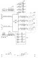
도 2a 및 도 2b 는 본 발명에 따른 주파수 변환/결합 기능을 갖는 옥외형 광송수신 장치 및 그 방법과, 케이블TV 헤드엔드 시스템에서의 주파수 변환/결합 장치 및 그 방법에 대한 일실시예 설명도로서, 한 개의 셀(Cell)에 대한 것을 나타낸다. 여기서는, 편의상 4개의 하향채널들(A, B, C, D)과 8개의 상향채널(E, F, G, H, I, J, K, L)을 전송하는 경우로 가정하고, 또한 상향 8개 채널들은 5~42MHz 상향대역을 사용하는 4개의 채널들(E, F, G, H)과 IUC(In-Band Upstream Channel)인 4개의 채널들(I, J, K, L)로 구성된다고 가정한다.2A and 2B are diagrams illustrating an exemplary embodiment of an outdoor optical transmission / reception apparatus having a frequency conversion / combination function and a method thereof, and a frequency conversion / combination device and a method thereof in a cable TV headend system. Represents one cell. For convenience, it is assumed that four downlink channels A, B, C, and D and eight uplink channels E, F, G, H, I, J, K, and L are transmitted. The four channels consist of four channels (E, F, G, H) using the 5 to 42 MHz upband and four channels (I, J, K, L), which are In-Band Upstream Channels (IUC). Assume
디지털 케이블TV 헤드엔드 시스템에서의 주파수 변환/결합 장치(200)는 업컨버터(up-converter)(212), 주파수결합기(214), 전광변환기(216), 광전변환기(218), 주파수분배기(220), 및 다운컨버터(down-converter)(222) 등으로 구성되는데, 이에 대한 각각의 기능은 하향 전송 과정과 상향 전송 과정을 설명하면서 함께하기로 한다.The frequency converting / combining
먼저, 하향신호가 헤드엔드 시스템(100)으로부터 가입자들에게 전달되는 과정을 설명하면, 다음과 같다.First, a process of transmitting a downlink signal from the
헤드엔드 시스템(100)에서의 케이블 모뎀(210)은 헤드엔드 시스템내의 시스템 서버(예를 들면, SI, SMS, CAS 등)(202), 응용 서버(예를 들면, VOD 서버, 게임 서버 등)(204), 오디오/비디오(A/V) 인코더(206), 인터넷 백본망(Internet Backbone)(208) 등을 통해 가입자들에 전송할 데이터들을 입력받고, 그 입력받은 데이터들을 각 데이터들의 최종 목적지에 해당되는 서브셀(Sub Cell)(231, 232, 233, 234)들과 일대일(1:1) 매핑한 후 4개의 중간주파수(IF)출력 포트를 통하여 하향 채널들(A, B, C, D)을 출력한다(211 참조). 여기서, 'A', 'B', 'C', 'D'는 중간주파수(IF) 하향신호이다.The
업컨버터(Up-converter)(212)가 케이블 모뎀(210)으로부터 입력 받은 하향 채널들을 '「동축케이블 가용주파수대역」이상의 대역'(이하, SB대역이라 한다)으 로 각각 주파수 변환하여 출력한다(213 참조). 이 때, 출력신호는 A[RF1], B[RF2], C[RF3], D[RF4]이며, 여기서 RF1, RF2, RF3, RF4는 중심주파수가 SB 대역내에 존재하는 하향 RF 신호를 나타낸다.The up-
주파수결합기(Combiner)(214)가 업컨버터(up-converter)(212)로부터 입력받은 하향 SB대역 채널들과 「동축케이블 가용주파수대역」 내의 방송신호인 「동축케이블 가용주파수대역내 방송신호(In-Band신호)」를 결합하여 출력하면(217 참조), 전광변환기(216)는 주파수결합기(Combiner)(214)의 출력(하향 전기신호)을 하향 광신호로 변환하여 옥외형 광송수신장치(ONU)(224)로 출력한다({A[RF1] + B[RF2] + C[RF3] + D[RF4]} + 「동축케이블 가용주파수대역내 방송신호(In-Band신호)」)(217 참조). 여기서, RF1, RF2, RF3, RF4는 중심주파수가 SB 대역내에 존재하는 하향 RF 신호를 나타낸다.The broadcast signal in the coaxial cable available frequency band (In-), which is a broadcast signal in the downlink SB band channels received from the up-
옥외형 광송수신장치(ONU)(224)는 광케이블 네트워크(130)를 통하여 전광변환기(216)로부터 전송된 'SB대역을 통해 전송되는 하향 신호들'을 「동축케이블 가용주파수대역」으로 각각 주파수 변환한다. 이 때, 각 하향 신호의 중심 주파수는 [RF13]MHz로 「동축케이블 가용주파수대역」 내의 값이다.The outdoor optical transmitter / receiver (ONU) 224 converts the frequency of 'downlink signals transmitted through the SB band' transmitted from the all-
그리고 나서, 옥외형 광송수신장치(ONU)(224)는 중심주파수 [RF13]MHz로 주파수 변환된 4개의 하향 채널들을 「동축케이블 가용주파수대역내 방송신호」(즉, In-Band신호)와 결합한 후 각각의 동축케이블들을 통해 해당되는 서브셀(Sub Cell)(231, 232, 233, 234)들로 전달한다(225 참조).Then, the outdoor optical transmitter / receiver (ONU) 224 combines four downlink channels, which are frequency-converted to the center frequency [RF13] MHz, with a broadcast signal in a coaxial cable available frequency band (ie, an in-band signal). Each coaxial cable is transferred to the
즉, 옥외형 광송수신장치(ONU)(224)는 각각의 동축케이블을 통하여 서브셀 1(231)로는 'A[RF13] + 「동축케이블 가용주파수대역내 방송신호(In-Band신호)」', 서브셀2(232)로는 'B[RF13] + 「동축케이블 가용주파수대역내 방송신호(In-Band신호)」', 서브셀3(233)으로는 'C[RF13] + 「동축케이블 가용주파수대역내 방송신호(In-Band신호)」', 서브셀4(234)로는 'D[RF13]+ 「동축케이블 가용주파수대역내 방송신호(In-Band신호)」'를 전송한다. 여기서, RF13은 중심주파수가 「동축케이블 가용주파수대역」내에 존재하는 하향 RF 신호를 나타낸다.That is, the outdoor optical transmitter / receiver (ONU) 224 transmits the sub-cell 1 231 through the respective coaxial cables to 'A [RF13] +' broadcast signal in the available frequency band (In-Band signal) ', Subcell 2 232 is' B [RF13] + 'broadcast signal in coaxial cable available frequency band' (In-Band signal) ', and in subcell 3 (233)' C [RF13] + 'in coaxial cable available frequency band' Broadcast signal (In-Band signal) 'and sub-cell 4 (234) transmit' D [RF13] + 'broadcast signal in coaxial cable available frequency band (In-Band signal)'. Here, RF13 represents a downlink RF signal in which the center frequency exists in the "coaxial cable available frequency band."
한편, 서브셀의 가입자로부터 옥외형 광송수신장치(224)를 통하여 헤드엔드 시스템(100)으로 상향 신호를 전송하는 과정을 설명하면, 다음과 같다.Meanwhile, a process of transmitting an uplink signal from the subscriber of the subcell to the
옥외형 광송수신장치(224)는 각 서브셀(Sub Cell)들(231, 232, 233, 234)로부터 5~42MHz 상향대역을 사용하는 상향 채널들(E, F, G, H)과 또 다른 대역을 사용하는 IUC들(I, J, K, L)을 4개의 동축케이블들을 통해 입력받는다(229 참조). 즉, 옥외형 광송수신장치(224)는 서브셀1(231)로부터는 'E[RF14] + I[RF15]', 서브셀2(232)로부터는 'F[RF14]+ J[RF15]', 서브셀3(233)으로부터는 'G[RF14] + K[RF 15]', 서브셀4(234)로부터는 'H[RF14] + L[RF15]'를 입력받는다. 여기서, RF14는 중심주파수가 5~42MHz인 상향 RF 신호, RF15는 중심주파수가 '5~42MHz 상향대역'을 제외한 「동축케이블 가용주파수대역」내에 존재하는 상향신호를 나타낸다.The outdoor optical transmitter /
옥외형 광송수신장치(224)는 각각의 서브셀(231, 232, 233, 234)로부터 동축케이블 네트워크(140)를 통하여 입력받은 E[RF14], F[RF14], G[RF14], H[RF14], I[RF15], J[RF15], K[RF15], L[RF15] 신호들을 「동축케이블 가용주파수대역」 내로 각각 주파수 변환한 후 결합하여(227 참조) 헤드엔드 시스템측으로 출력한다. 이 때, 옥외형 광송수신장치(224)의 출력신호는 "227"에서의 E[RF5], F[RF6], G[RF7], H[RF8], I[RF9], J[RF10], K[RF11], L[RF12]와 같으며, 여기서 RF5 ~ RF12는 중심주파수가 '5~42MHz 상향대역'과 「동축케이블 가용주파수대역」내에 존재하는 상향신호를 나타낸다.The outdoor optical transmitter /
광전변환기(218)는 옥외형 광송수신장치(224)에서 출력되어 광케이블 네트워크(130)를 통하여 전송된 '주파수 다중화된 상향 광신호들'(227)을 입력받아, 상향 전기신호로 변환한 후, 주파수분배기(Splitter)(220)로 출력한다.The photoelectric converter 218 receives 'frequency multiplexed uplink optical signals' 227 output from the outdoor optical transmitter /
그러면, 주파수분배기(Splitter)(220)는 다중화된 상향 전기신호들을 8개의 신호(E[RF5], F[RF6], G[RF7], H[RF8], I[RF9], J[RF10], K[RF11], L[RF12])로 분할하여(221) 다운컨버터(down-converter)(222)로 출력한다. 여기서, RF5~RF12는 중심주파수가 '5~42MHz 상향대역'과 「동축케이블 가용주파수대역」내에 존재하는 상향신호를 나타낸다.Then, the
다운컨버터(down-converter)(222)는 주파수분배기(Splitter)(220)로부터 입력받은 상향 전기신호들(221 참조)을 중간주파수(IF)신호로 각각 주파수 다운컨버팅(down-converting)하여 케이블 모뎀(210)으로 출력한다. 여기서, 다운컨버터 (down-converter)(222)의 출력신호는 "223"에서와 같이 'E', 'F', 'G', 'H', 'I', 'J', 'K', 'L' 등의 8개의 중간주파수(IF)의 상향신호이다.The down-
케이블 모뎀(210)은 입력받은 상향신호(223)를 시스템 서버(202), 응용서버(204), 인터넷 백본망(Internet Backbone)(208) 중 해당되는 곳으로 출력한다.The
도 3 은 본 발명에 따른 주파수 변환/결합 기능을 갖는 옥외형 광송수신장치 (ONU)의 일실시예 구성도이다.3 is a configuration diagram of an embodiment of an outdoor optical transmitting / receiving device (ONU) having a frequency converting / coupling function according to the present invention.
본 발명에 따른 주파수 변환/결합 기능을 갖는 옥외형 광송수신장치 (ONU)(224)는 하향 광전변환부(301), 하향 주파수 변환 및 결합부(302), 국부발진부(303), 상태제어 및 감시부(304), 상하향 대역분리부(305), 상향 주파수 변환 및 결합부(306), 및 상향 전광변환부(307) 등으로 구성된다.Outdoor type optical transmitter / receiver (ONU) 224 having a frequency conversion / coupling function according to the present invention includes a downlink
도 2a 및 도 2b의 설명 과정에서는 4개의 하향채널들과 8개의 상향채널들을 전송하는 것으로 가정하였으며, 여기서 상향 8개 채널들은 5~42MHz 상향대역을 사용하는 4개의 채널(E, F, G, H)들과, IUC인 4개의 채널(I, J, K, L)들로 구성된다.In the description process of FIGS. 2A and 2B, it is assumed that four downlink channels and eight uplink channels are transmitted, wherein the eight uplink channels use four channels (E, F, G, H) and four channels (I, J, K, L) which are IUC.
하향 광전변환부(301)는 광케이블 네트워크(130)로부터 「동축케이블 가용주파수대역내 방송신호(In-Band신호)」와 SB대역신호를 포함하고 있는 하향 광신호를 입력받아 하향 전기신호로 변환하여 하향 주파수 변환 및 결합부(302)로 출력한다.The downlink
하향 주파수 변환 및 결합부(302)는 하향 광전변환부(301)가 출력한 SB대역의 RF신호를 입력받아, SB대역내에 존재하는 4개의 하향 채널들(217)을 주파수변환을 통해 「동축케이블 가용주파수대역」내에서 중심주파수를 갖는 신호들(225)로 변환한 후, 「동축케이블 가용주파수대역」으로 주파수 변환된 각 신호들을 상하향 대역 분리부(305)로 출력한다. 이 때, 주파수 변환에 필요한 국부발진주파수는 국부발진부(303)로부터 입력받으며, 상태신호를 상태제어 및 감시부(304)로 출력함으로써 신호를 감시할 수 있도록 한다.The
한편, 상향 주파수 변환 및 결합부(306)는 상하향 대역분리부(305)로부터 5~42MHz상향대역신호와 IUC대역 상향신호로 분리되어 입력되는 상향 신호들(229) 을, 주파수 변환을 통해 「동축케이블 가용주파수대역」 내의 서로 겹치지 않는 8개의 채널들로 주파수 변환한다(227 참조). 이 때, 주파수 변환에 필요한 국부발진주파수는 국부발진부(303)로부터 입력받으며, 상태신호를 상태제어 및 감시부(304)로 출력해 신호를 감시할 수 있도록 한다.Meanwhile, the uplink frequency converting and combining
상향 전광변환부(307)는 상향 주파수 변환 및 결합부(306)로부터 「동축케이블 가용주파수대역」에 해당되는 상향 전기신호를 입력받아 광신호로 변환한 후 광케이블 네트워크(130)로 출력한다.The uplink all-optical converting
국부발진부(303)는 하향 주파수 변환 및 결합부(302)와 상향 주파수 변환 및 결합부(306)에서 주파수 변환시 필요로 하는 국부발진주파수를 생성하여, 하향 주파수 변환 및 결합부(302)와 상향 주파수 변환 및 결합부(306)로 전송한다. 또한, 국부발진주파수 생성에 필요한 제어신호를 상태제어 및 감시부(306)로부터 입력받는다.The
상태제어 및 감시부(304)는 하향 주파수 변환 및 결합부(302)와 상향 주파수 변환 및 결합부(306)로부터 상태정보를 입력받아 계측기 등으로 출력한다. 또한, 국부발진부(303)로 국부 발진 주파수 생성에 필요한 제어 정보를 출력한다.The state control and
상하향 대역분리부(305)는 하향 주파수 변환 및 결합부(302)로부터 입력받은 「동축케이블 가용주파수대역」에 해당되는 4개의 하향 신호들을 각각 대응되는 동축케이블들로 출력하며, 또한 동축케이블들을 통하여 각각의 서브셀(231, 232, 233, 234)로부터 입력받은 5~42MHz와 IUC대역에 해당되는 상향 신호들을 상향 주파수 변환 및 결합부(306)로 출력한다.The up-down
도 4 는 본 발명에 따른 도 3의 하향 주파수 변환 및 결합부의 일실시예 상세구성도이다.4 is a detailed configuration diagram of an embodiment of the downlink frequency converter and combiner of FIG. 3 according to the present invention.
하향 주파수 변환 및 결합부(302)는 도 4에 도시된 바와 같이, 대역분리기(401), 다수의 다운컨버터(DC)(411, 412, 413, 414), 다수의 자동이득조절기(AGC)(421, 422, 423, 424) 등으로 구성된다.As shown in FIG. 4, the downlink frequency converter and
설명의 편의상, 4개의 하향채널들과 8개의 상향채널을 전송하는 경우로 가정하였으며, 여기서 상향 8개 채널들은 '5~42MHz 상향대역'을 사용하는 4개의 채널들(E, F, G, H)과, IUC대역인 4개의 채널들(I, J, K, L)로 구성된다고 본다.For convenience of explanation, it is assumed that four downlink channels and eight uplink channels are transmitted, wherein eight uplink channels use four channels (E, F, G, H) using '5-42 MHz uplink'. ) And four channels (I, J, K, L) that are IUC bands.
먼저, 대역분리기(401)는 하향 광전변환부(301)로부터 「동축케이블 가용주파수대역」신호와 SB대역 신호들을 입력받아 「동축케이블 가용주파수대역내 방송신호(In-Band신호)」와 SB대역에 해당되는 하향 신호로 분리하여 출력하며, 이때 SB대역에 포함되는 하향 신호는 4개의 신호로 분리하여 출력한다. 그리고, 입력되는 신호를 분기하여 상태감시 및 제어부(18)로 출력한다.First, the
제 1 다운컨버터(DC: down-converter)(1st DC)(411)는 대역분리기(401)로부터 SB대역 신호를 입력받아, SB대역 내 첫 번째 채널을 BPF로 필터링(추출)한 후, 믹서(mixer)를 사용해 중심주파수가 RF13(「동축케이블 가용주파수대역」내에 중심주파수 존재)이 되도록 주파수 변환을 수행한 다음, 그 주파수 변환된 채널을 제 1 자동이득조절기(1st AGC)(421)로 출력한다. 여기서, 믹서(mixer)를 통한 주파수 변환 과정에는 국부발진부(303)로부터 입력받은 국부발진주파수인 LO1이 사용된다.The first down-converter (DC) 1st DC (411) receives the SB band signal from the
나머지, 제 2 다운컨버터(DC)(2nd DC)(412), 제 3 다운컨버터(DC)(3rd DC)(413), 제 4 다운컨버터(DC)(4th DC)(414) 등도 제 1 다운컨버터(DC)(1st DC)(411)와 동일한 과정을 수행함으로써, 각각 SB대역 내의 두 번째, 세 번째, 네 번째 채널을 중심 주파수가 [RF13]인 곳으로 주파수 변환하여 각각의 해당 자동이득조절기(AGC)(422, 423, 424)로 출력한다.The second down converter (DC) (2nd DC) 412, the third down converter (DC) (3rd DC) 413, the fourth down converter (DC) (4th DC) 414, and the like are also first down. By performing the same process as the converter (DC) (1st DC) 411, each corresponding automatic gain regulator is frequency-converted to the place where the center frequency is [RF13] in each of the SB bands. Output to (AGC) (422, 423, 424).
제 1 자동이득조절기(1st AGC)(421)는 제 1 다운컨버터(DC)(1st DC)(411)로부터 중심주파수가 RF13인 채널('A')을 입력받아, 대역분리기(401)로부터 입력받은 「동축케이블 가용주파수대역내 방송신호(In-Band신호)」와 결합하여 '동축케이블 가용주파수대역 하향신호'를 생성한 후, 그 생성된 하향신호(즉, 「동축케이블 가용주파수대역내 방송신호(In-Band신호)」+ A[RF13])의 신호레벨을 일정하게 유지하면서 상하향 대역분리부(305)로 출력한다. 이 때, 출력 신호를 분기하여 상태제어 및 감시부(304)로 출력한다.The first automatic gain regulator (1st AGC) 421 receives a channel 'A' having a center frequency of RF13 from the first down converter (DC) (1st DC) 411 and inputs it from the
나머지 제 2 자동이득조절기(2nd AGC)(422), 제 3 자동이득조절기(3rd AGC)(423), 제 4 자동이득조절기(4th AGC)(424)들도 제 1 자동이득조절기(1st AGC)(421)와 동일한 기능을 수행한다.The remaining second automatic gain controller (2nd AGC) 422, the third automatic gain controller (3rd AGC) 423, the fourth automatic gain controller (4th AGC) (424) also the first automatic gain controller (1st AGC) Performs the same function as 421.
도 5 는 본 발명에 따른 도 3의 상향 주파수 변환 및 결합부의 일실시예 상세구성도이다.5 is a detailed configuration diagram of an embodiment of the uplink frequency converter and combiner of FIG. 3 according to the present invention.
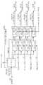
상향 주파수 변환 및 결합부(306)는 도 5에 도시된 바와 같이, 대역통과필터(501), 제 1 업컨버터(1st UC: 1st up-converter)(511), 제 2 업컨버터(2nd UC)(512), 제 3 업컨버터(3rd UC)(513), 주파수결합기(521), 및 자동이득조절기(AGC)(522)로 구성된다.As illustrated in FIG. 5, the uplink frequency converter and
설명의 편의상, 4개의 하향채널들과 8개의 상향채널을 전송하는 경우로 가정하였으며, 여기서 상향 8개 채널들은 '5~42MHz 상향대역'을 사용하는 4개의 채널들(E, F, G, H)과, IUC대역인 4개의 채널들(I, J, K, L)로 구성된다고 본다.For convenience of explanation, it is assumed that four downlink channels and eight uplink channels are transmitted, wherein eight uplink channels use four channels (E, F, G, H) using '5-42 MHz uplink'. ) And four channels (I, J, K, L) that are IUC bands.
대역통과필터(BPF)(501)는 IUC대역에 해당되는 BPF와 상향신호대역에 해당되는 BPF로 구성되는데, 제 1 상하향 대역분리기(801)로부터 IUC대역 신호(I[RF15])와 상향신호(E[RF14])를 각각 입력받아, IUC대역에 해당되는 BPF와 상향신호대역에 해당되는 BPF를 이용하여 각 신호들에 대해 필터링을 수행한 후(여기서, 필터링 결과는 I[RF9], E[RF5]임), 주파수결합기(521)로 출력한다. 또한, 대역통과필터 (BPF)(501)는 입력받은 신호를 분기하여 상태제어 및 감시부(304)로 출력하기도 한다.The band pass filter (BPF) 501 is composed of a BPF corresponding to the IUC band and a BPF corresponding to an uplink signal band, and the IUC band signal I [RF15] and the uplink signal from the first
제 1 업컨버터(1st UC)(511)는 제 2 상하향 대역분리기(802)로부터 IUC대역 신호(J[RF15])와 상향 신호(F[RF14])를 입력받으며, 또한, 국부발진부(303)로부터 주파수 변환에 필요한 국부발진 주파수 LO5, LO8을 입력받는다. 이후, 제 1 업컨버터(1st UC)(511)는 상향 신호를 믹서와 LO5를 이용하여 「동축케이블 가용주파수대역」 내 중심주파수가 RF6(도 2b의 "227" 참조)인 채널('F')로 주파수 변환한 후 주파수결합기(521)로 출력한다. 또한 제 1 업컨버터(1st UC)(511)는 IUC대역 신호를 믹서와 LO8을 이용하여 「동축케이블 가용주파수대역」 내의 중심주파수가 RF10(도 2b의 "227" 참조)인 채널('J')로 주파수 변환한 후, 주파수결합기(521)로 출력한다. 그리고, 입력받은 신호를 분기하여 상태제어 및 감시부(304)로 출력하기도 한다.The first up-converter (1st UC) 511 receives the IUC band signal J [RF15] and the upstream signal F [RF14] from the second up-
또한, 제 2 업컨버터(2nd UC)(512)와 제 3 업컨버터(3rd UC)(513)도 제 1 업컨버터(1st UC)(511)와 동일한 기능을 수행한다.In addition, the second up-converter (2nd UC) 512 and the third up-converter (3rd UC) 513 also perform the same functions as the first up-converter (1st UC) 511.
주파수결합기(521)는 대역통과필터(BPF)(501), 제 1 업컨버터(1st UC)(511), 제 2 업컨버터(2nd UC)(512), 제 3 업컨버터(3rd UC)(513) 등으로부터 주파수 변환된 상향신호와 IUC대역 신호를 입력받아 결합하여 '동축케이블 가용주파수대역 상향 전기신호'를 생성한 후, 그 생성된 상향 전기신호( E + F + G + H + I + J + K + L)를 자동이득조절기(AGC)(522)로 출력한다.The
자동이득조절기(AGC)(522)는 주파수결합기(521)로부터 입력받은 신호의 신호레벨을 일정하게 유지하면서 상향전광변환부(307)로 출력하며, 또한, 이 때 출력 신호를 분기하여 상태제어 및 감시부(304)로 출력한다.The automatic gain controller (AGC) 522 outputs to the
도 6 은 본 발명에 따른 도 3의 국부발진부의 일실시예 상세구성도이다.6 is a detailed configuration diagram of an embodiment of the local oscillator of FIG. 3 according to the present invention.
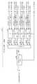
국부발진부(303)는 도 6에 도시된 바와 같이, 하향 위상잠금루프(PLL: Phase Locked Loop) 국부발진기(601), 기준주파수제공기(602), 및 상향 위상잠금루프 (PLL) 국부발진기 (603) 등으로 구성된다.As illustrated in FIG. 6, the
설명의 편의상, 4개의 하향채널들과 8개의 상향채널을 전송하는 경우로 가정하였으며, 여기서 상향 8개 채널들은 '5~42MHz 상향대역'을 사용하는 4개의 채널들(E, F, G, H)과, IUC대역인 4개의 채널들(I, J, K, L)로 구성된다고 본다.For convenience of explanation, it is assumed that four downlink channels and eight uplink channels are transmitted, wherein eight uplink channels use four channels (E, F, G, H) using '5-42 MHz uplink'. ) And four channels (I, J, K, L) that are IUC bands.
하향 PLL 국부발진기(601)는 상태제어 및 감시부(304)로부터는 제어 신호를 입력받고, 기준주파수 제공기(602)로부터는 기준 주파수 신호를 입력받아, 국부발진 신호(LO0, LO2, LO3, LO4)를 생성하여 하향 주파수 변환 및 결합부(302)로 출력 한다. 또한, 하향 PLL 국부발진기(601)는 국부발진 생성정보를 상태제어 및 감시부(304)로 출력한다.The downlink PLL
상향 PLL 국부발진기(603)는 상태제어 및 감시부(18)로부터는 제어 신호를 입력받고, 기준주파수 제공기(602)로부터는 기준 주파수신호를 입력받아, 국부발진 신호(LO5, LO6, LO7, LO8, LO9, LO10)를 생성하여 상향 주파수 변환 및 결합부(306)로 출력한다. 또한 상향 PLL 국부발진기(603)는 국부발진 생성정보를 상태제어 및 감시부(304)로 출력한다.The uplink PLL
기준주파수제공기(602)는 특정 주파수의 국부발진신호를 생성하는데 필요한 기준주파수를 제공하는 것으로서, 이러한 기준주파수 신호를 생성하여 하향 PLL 국부발진기(601)와 상향 PLL 국부발진기(603)로 출력한다.The
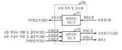
도 7 은 본 발명에 따른 도 3의 상태제어 및 감시부의 일실시예 상세구성도로서, 상태 제어 및 감시부(304)는 도면에 도시된 바와 같이, 제어정보 처리기(701)와 상태정보 처리기(702)로 구성된다.7 is a detailed configuration diagram of the state control and monitoring unit of FIG. 3 according to the present invention. As shown in the figure, the state control and
제어정보 처리기(701)는 운용자단말로부터 PLL 제어신호를 입력받아 국부발진부(303)로 전달하고, 상태정보 처리기(702)는 하향 주파수 변환 및 결합부(302), 상향 주파수 변환 및 결합부(306), 국부발진부(303)로부터 상태정보를 입력받아 상태표시기(예를 들면, LED 등) 및 계측기로 출력한다.The
도 8 은 본 발명에 따른 도 3의 상하향 대역분리부의 일실시예 상세구성도이다.8 is a detailed configuration diagram of an embodiment of the up-down band separation unit of FIG. 3 according to the present invention.
제 1 상하향 대역분리기(801)는 옥외형 광송수신장치(ONU)(224)에 연결된 제 1 동축케이블로부터 IUC대역과 상향 신호대역을 통해 입력되는 상향 신호(예를 들면, E[RF14] + I[RF15])(도2에서의 "229" 참조)를 IUC대역신호(I[RF15])와 상향 신호대역신호(5~42MHz)(E[RF14])로 분리하여 상향 주파수 변환 및 결합부(306)로 출력한다. 또한, 하향 주파수 변환 및 결합부(302)로부터 하향신호, 즉 「동축케이블 가용주파수대역내 방송신호(In-Band신호)」와 A[RF13]를 입력받아 필터링을 수행한 후 제 1 동축케이블로 출력한다(도 9 참조).The first up-
한편, 제 2 상하향 대역분리기(802), 제 3 상하향 대역분리기(803), 제 4 상하향 대역분리기(804)도 위에서 설명한 제 1 상하향 대역분리기(801)와 동일한 기능을 수행한다.Meanwhile, the second up-
도 9 는 본 발명에 따른 도 8의 상하향 대역분리기의 일실시예 상세구성도이다.9 is a detailed configuration diagram of an embodiment of the up-down band separator of FIG. 8 according to the present invention.
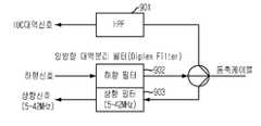
고역통과필터(HPF)(901)는 동축케이블을 통하여 전달된 상향신호(즉, IUC대역신호 + 5~42MHz 상향신호)를 입력받아 필터링을 통하여 IUC대역신호를 출력하고, 양방향 대역분리 필터(Diplex Filter)에서의 상향필터(903)는 상기 상향신호 중에서 '5~42MHz 상향대역' 신호(즉, 5~42MHz 상향신호)만을 출력한다.The high pass filter (HPF) 901 receives an uplink signal (ie, an IUC band signal + a 5 to 42 MHz uplink signal) transmitted through a coaxial cable, outputs an IUC band signal through filtering, and a bidirectional band separation filter (Diplex). The
예를 들어, 제 1 상하향 대역분리기(801)의 경우를 살펴보면, 고역통과필터 (HPF)(901)는 제 1 동축케이블을 통하여 전달된 상향신호(즉, E[RF14] + I[RF15])를 입력받아 필터링을 통하여 IUC대역신호(I[RF15])를 출력하고, 양방향 대역분리 필터(Diplex Filter)에서의 상향필터(903)는 상기 상향신호 중에서 '5~42MHz 상향대역' 신호(즉, 5~42MHz 상향신호(E[RF14]))만을 출력한다.For example, referring to the case of the first up-
한편, 양방향 대역분리 필터(Diplex Filter)에서의 하향필터(902)는 '동축케이블 가용주파수대역 하향신호'(예를 들어, 제 1 상하향 대역분리기(801)의 경우에는, E[RF14] + I[RF15])를 입력받아 필터링을 수행하여 제 1 동축케이블로 출력한다.On the other hand, the
도 8에서의 제 1 상하향 대역분리기(801), 제 2 상하향 대역분리기(802), 제 3 상하향 대역분리기(803), 제 4 상하향 대역분리기(804) 모두 위에서 설명한 상하향 대역분리기와 구성 및 기능이 동일하다.In FIG. 8, the first up-
도 10a 및 도 10b 는 본 발명에 따른 옥외형 광송수신 장치(ONU)에서의 하향/상향 주파수 변환/결합 방법에 대한 일실시예 흐름도로서, 도 10a는 하향 주파수 변환/결합 방법을 나타내고, 도 10b는 상향 주파수 변환/결합 방법를 나타낸다. 이미 앞에서 옥외형 광송수신 장치(ONU)를 설명하면서 상세히 설명하였으므로, 여기서는 전반적인 과정만을 설명하기로 한다.10A and 10B are flowcharts of one embodiment of a downlink / uplink frequency converting / combining method in an outdoor optical transmitting / receiving device (ONU) according to the present invention, and FIG. 10A shows a downlink frequency converting / combining method, and FIG. 10B. Denotes an uplink frequency conversion / combining method. Since the foregoing description has been made in detail while describing the outdoor type optical transmitting and receiving unit (ONU), only the overall process will be described.
먼저, 도 10a에 도시된 바와 같은 하향 주파수 변환/결합 방법에 대하여 설명하면, 다음과 같다.First, a downlink frequency conversion / combining method as illustrated in FIG. 10A will be described.
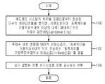
옥외형 광송수신 장치(ONU)(224)는 헤드엔드 시스템(100)으로부터 광케이블 네트워크(130)를 통하여 하향 광신호를 받으면, 이를 하향 전기신호로 변환한다 (1000).When the outdoor type optical transmitting / receiving device (ONU) 224 receives the downlink optical signal from the
이후, 옥외형 광송수신 장치(ONU)(224)는 하향 전기신호를 「동축케이블 가용주파수대역」으로 전송되는 「동축케이블 가용주파수대역내 방송신호(In-Band신호) 」와 '「동축케이블 가용주파수대역」이상의 대역신호(SB대역신호)'로 분리하 고(1002), 상기 SB대역신호에 포함된 각각의 채널신호마다 분리하여 「동축케이블 가용주파수대역」 내의 하향신호로 주파수 변환한 후(1004) 주파수변환된 각각의 하향신호를 「동축케이블 가용주파수대역내 방송신호(In-Band신호)」와 결합하여 '동축케이블 가용주파수대역 하향신호'를 생성한다(1006).Thereafter, the outdoor type optical transmission / reception unit (ONU) 224 transmits the downlink electric signal to the "coaxial cable available frequency band" and "in-band signal in the coaxial cable available frequency band" and "coaxial cable available frequency." Band signal (SB band signal) of " more than band " (1002), each channel signal included in the SB band signal is separated and frequency-converted to a downlink signal in the "coaxial cable available frequency band" (1004). Each frequency-converted downlink signal is combined with an in-band signal within a coaxial cable available frequency band to generate a coaxial cable available frequency band downlink signal (1006).
그리고 나서, 옥외형 광송수신 장치(ONU)(224)는 "1006"에서 생성된 각각의 '동축케이블 가용주파수대역 하향신호'를 해당 동축케이블로 출력한다(1008).Then, the outdoor type optical transmission / reception unit (ONU) 224 outputs the respective 'coaxial cable available frequency band downlink signal' generated at '1006' to the corresponding coaxial cable (1008).
다음으로는, 도 10b에 도시된 바와 같은 상향 주파수 변환/결합 방법에 대하여 설명하면, 다음과 같다.Next, an uplink frequency conversion / combining method as illustrated in FIG. 10B will be described.
옥외형 광송수신 장치(ONU)(224)는 각각의 가입자 서브셀로부터 동축케이블을 통하여 전달받으면, 그 전달된 상향신호마다 '케이블TV상향주파수대역(즉, 5~42MHz 상향대역) 신호'와 '케이블TV상향주파수대역(즉, 5~42MHz 상향대역)을 제외한 「동축케이블 가용주파수대역」내의 다른 상향채널 대역신호(IUC대역신호)'로 분리한다(1010).When the outdoor optical transmitting / receiving device (ONU) 224 receives a coaxial cable from each subscriber subcell, the cable TV uplink frequency band (ie, 5 to 42 MHz uplink signal) and 'for each transmitted uplink signal' and ' The signal is separated into another uplink channel signal (IUC band signal) in the "coaxial cable available frequency band" excluding the cable TV uplink frequency band (i.e., 5 to 42 MHz uplink band) (1010).
이후, 옥외형 광송수신 장치(ONU)(224)는 "1010"(즉, 대역분리 단계)에서 '케이블TV상향주파수대역(즉, 5~42MHz 상향대역) 신호'와 IUC대역 신호로 분리된 상향신호들을, 「동축케이블 가용주파수대역」 내의 서로 중복되지 않는 채널들로 주파수 변환한 후(1012), 그 변환된 채널신호들을 결합하여 '동축케이블 가용주파수대역 상향 전기신호'를 생성한다(1014).Thereafter, the outdoor type optical transmission / reception unit (ONU) 224 is an uplink divided into a 'cable TV uplink frequency band signal (that is, 5 to 42 MHz uplink band) signal' and an IUC band signal at " 1010 " The signals are frequency-converted into channels that do not overlap each other in the "coaxial cable available frequency band" (1012), and then the converted channel signals are combined to generate a "coaxial cable available frequency band uplink electric signal" (1014). .
그리고 나서, 옥외형 광송수신 장치(ONU)(224)는 그 생성된 '동축케이블 가용주파수대역상향 전기신호'를, 광케이블 네트워크를 통하여 헤드엔드 시스템으로 전송하기 위하여, 상향 광신호로 변환한다(1016).The outdoor optical transceiver (ONU) 224 then converts the generated 'coaxial cable available frequency band up electrical signal' into an uplink optical signal for transmission to the headend system via the optical cable network (1016). ).
도 11a 및 도 11b 는 본 발명에 따른 케이블 티브이 헤드엔드 시스템에서의 하향/상향 주파수 변환/결합 방법에 대한 일실시예 흐름도로서, 도 11a는 하향 주파수 변환/결합 방법을 나타내고, 도 11b는 상향 주파수 변환/결합 방법을 나타낸다. 이미 앞에서 옥외형 광송수신 장치(ONU)를 명하면서 상세히 설명하였으므로, 여기서는 전반적인 과정만을 설명하기로 한다.11A and 11B are flowcharts illustrating one embodiment of a downlink / uplink frequency converting / combining method in a cable TV headend system according to the present invention, and FIG. 11A illustrates a downlink frequency converting / combining method, and FIG. The conversion / combination method is shown. As described above in detail while ordering the outdoor optical transmitting and receiving unit (ONU), only the overall process will be described.
먼저, 도 11a에 도시된 바와 같은, 케이블 티브이 헤드엔드 시스템에서의 하향 주파수 변환/결합 방법에 대하여 설명하면, 다음과 같다.First, a downlink frequency conversion / combining method in a cable TV headend system as shown in FIG. 11A will be described.
헤드엔드 시스템(보다 정확하게는 헤드엔드 시스템에서의 주파수 변환/결합 장치(200)를 말함)은 케이블 모뎀(210)으로부터 다수의 하향신호들을 전송받으면, 그 전송받은 하향신호마다 '동축케이블 가용주파수대역 이상의 대역(SB대역)'으로 주파수 업컨버팅(up-converting)한다(1100).When the headend system (more precisely referred to as the frequency conversion / combining
이후, 헤드엔드 시스템은 "1100"의 주파수 업컨버팅(up-converting) 단계에서 변환된 SB대역 하향신호와 「동축케이블 가용주파수대역」으로 전송되는 「동축케이블 가용주파수대역내 방송신호(In-Band신호)」를 결합한 후(1102), 그 결합된 하향 전기신호를 광케이블 네트워크로 전송하기 위하여 하향 광신호로 변환한다(1104).Subsequently, the headend system transmits the SB band downlink signal converted in the frequency up-converting step of “1100” and the “in-band signal in the coaxial cable available frequency band” transmitted in the “coaxial cable available frequency band”. ), And converts the combined downlink electrical signal into a downlink optical signal for transmission to an optical cable network (1104).
다음은, 도 11b에 도시된 바와 같은, 케이블 TV 헤드엔드 시스템에서의 상향 주파수 변환/결합 방법에 대하여 설명하면, 다음과 같다.Next, an uplink frequency conversion / combining method in the cable TV headend system as shown in FIG. 11B will be described.
헤드엔드 시스템(보다 정확하게는 헤드엔드 시스템에서의 주파수 변환/결합 장치(200)를 말함)은 광케이블 네트워크를 통하여 옥외형 광송수신장치(ONU)로부터 상향 광신호를 받으면, 그 전송받은 상향 광신호를 상향 전기신호로 변환한다(1110).When the headend system (more precisely, the frequency conversion / combining
그리고 나서, 헤드엔드 시스템은 "1110"에서 변환된 상향 전기신호를 채널별로 분할한 후(1112), 그 분할된 각각의 상향 전기신호를 헤드엔드(Headend) 시스템의 케이블 모뎀(210)으로 전송하기 위하여, 중간주파수(IF)신호로 주파수 다운컨버팅(down-converting)한다(1114).Then, the head-end system divides the uplink electrical signal converted in " 1110 " by
상술한 바와 같은 본 발명의 방법은 프로그램으로 구현되어 컴퓨터로 읽을 수 있는 형태로 기록매체(씨디롬, 램, 롬, 플로피 디스크, 하드 디스크, 광자기 디스크 등)에 저장될 수 있다. 이러한 과정은 본 발명이 속하는 기술 분야에서 통상의 지식을 가진 자가 용이하게 실시할 수 있으므로 더 이상 상세히 설명하지 않기로 한다.As described above, the method of the present invention may be implemented as a program and stored in a recording medium (CD-ROM, RAM, ROM, floppy disk, hard disk, magneto-optical disk, etc.) in a computer-readable form. Since this process can be easily implemented by those skilled in the art will not be described in more detail.
이상에서 설명한 본 발명은, 본 발명이 속하는 기술분야에서 통상의 지식을 가진 자에게 있어 본 발명의 기술적 사상을 벗어나지 않는 범위 내에서 여러 가지 치환, 변형 및 변경이 가능하므로 전술한 실시예 및 첨부된 도면에 의해 한정되는 것이 아니다.The present invention described above is capable of various substitutions, modifications, and changes without departing from the technical spirit of the present invention for those skilled in the art to which the present invention pertains. It is not limited by the drawings.
상기와 같은 본 발명은, 디지털 CATV 전송시스템에 있어서, 전송속도를 높이기 위해 셀(Cell)들을 더 작은 셀(Cell)들로 분할하는 기존의 기술과 달리, 한 개 의 셀(Cell) 내에 위치하는 서브셀(Sub Cell)들에게 서로 다른 하향 신호를 전송함으로써, Cell분할을 하는데 필요한 막대한 경제적, 시간적 지출을 방지하면서도 전송속도를 높일 수 있게 하는 효과가 있다.As described above, in the digital CATV transmission system, unlike the conventional technology of dividing cells into smaller cells in order to increase the transmission speed, the present invention is located in one cell. By transmitting different downlink signals to subcells, it is possible to increase the transmission speed while preventing the huge economic and time expenditure required for cell division.
또한, 본 발명은 각 동축케이블마다 서로 다른 케이블신호(하향신호)를 전송하여 각각의 서브셀(Sub Cell)에는 해당 케이블 신호만이 전송되게 함으로써, 전송효율을 높이는 효과가 있다. 예를 들어, ONU에 4개의 동축케이블들이 연결되어 있다면, 기존 시스템보다 전송효율을 4배 높일 수 있는 효과가 있다는 것이다.In addition, the present invention transmits different cable signals (downward signals) for each coaxial cable so that only the corresponding cable signals are transmitted to each subcell, thereby increasing transmission efficiency. For example, if four coaxial cables are connected to the ONU, the transmission efficiency is four times higher than that of the existing system.
또한, 본 발명은, 광케이블 네트워크의 높은 가용 주파수 대역을 이용하여 가입자들로 케이블신호(하향신호)를 전송함으로써, 네트워크 자원의 활용 및 전송효율을 높이는 효과가 있다.In addition, the present invention, by using the high available frequency band of the optical cable network to transmit the cable signal (downward signal) to the subscribers, there is an effect of increasing the utilization of network resources and transmission efficiency.
또한, 본 발명은, 기존의 케이블TV상향주파수대역(즉, 5~42MHz 상향대역) 내 상향신호와 IUC(In-Band Upstream Channel)대역 신호도 「동축케이블 가용주파수대역」내에서 다중화를 할 수 있기 때문에, 보다 효율적인 상향신호 전송을 가능하게 하는 효과가 있다.In addition, the present invention can also multiplex the uplink signal and the IUC (In-Band Upstream Channel) band signal in the existing cable TV uplink frequency band (i.e., 5 to 42 MHz upband). There is an effect of enabling more efficient uplink signal transmission.
또한, 본 발명은, 옥외형 광송수신장치(ONU)에 연결된 각각의 동축케이블을 통하여 입력되는 상향 신호들을 옥외형 광송수신장치(ONU)에서 「동축케이블 가용주파수대역」내의 서로 다른 채널(즉, IUC)들로 중복되지 않도록 주파수 변환하여 전송할 수 있게 함으로써, 케이블 신호들간의 상호출돌을 방지하여 전송 효율을 높이는 효과가 있다.In addition, the present invention, the uplink signals input through each coaxial cable connected to the outdoor optical transmitting and receiving device (ONU) in different channels in the "coaxial cable available frequency band" in the outdoor optical transmitting and receiving device (ONU) (that is, By converting and transmitting frequency conversion so as not to overlap with IUCs, there is an effect of preventing transmission between cable signals and increasing transmission efficiency.
또한, 본 발명은 기존 5~42MHz 상향대역을 통한 상향신호의 전달뿐만 아니라 IUC 대역을 통한 상향 신호의 전달도 가능하기 때문에, 향후 상향 전송속도를 향상시키기 위하여 기존 IUC대역을 사용할 필요가 발생할 경우에도 별도의 과정없이 그대로 상향채널로 운용할 수 있는 효과가 있다.In addition, since the present invention can transmit the uplink signal through the IUC band as well as the uplink signal through the existing 5 ~ 42MHz uplink, even if the need to use the existing IUC band to improve the uplink transmission rate in the future There is an effect that can be operated in the up channel as it is without a separate process.
또한, 본 발명은, 동축케이블 네트워크에서는 기존 주파수 대역과 같은 대역 상에서 케이블 신호를 전달하기 때문에, 수신 단말을 포함한 동축케이블 네크워크 설비의 변경없이 케이블신호의 송수신을 가능하게 하는 효과가 있다.In addition, the present invention, because the coaxial cable network transmits the cable signal in the same band as the existing frequency band, there is an effect that enables the transmission and reception of the cable signal without changing the coaxial cable network equipment including the receiving terminal.
요컨대, 본 발명은, 헤드엔드와 옥외형 광송수신장치(ONU)사이의 광케이블 네트워크상에서 하향의 경우에는 SB대역에서, 상향의 경우 「동축케이블 가용주파수대역」에서 케이블신호가 전송되도록 하고, 한편 동축케이블 네트워크에서는 기존 주파수 대역과 같은 대역상에서 케이블 신호를 전달할 수 있게 함으로써, 네트워크 자원의 활용 및 전송 효율을 증가시키고, 또한 수신 단말을 포함한 동축케이블 네크워크 설비의 변경없이 케이블신호의 송수신을 가능하게 하는 효과가 있다.In short, the present invention allows the cable signal to be transmitted in the SB band in the downward direction and in the "coaxial cable available frequency band" in the upward direction on the optical cable network between the headend and the outdoor optical transceiver (ONU). In the cable network, the cable signal can be transmitted in the same band as the existing frequency band, thereby increasing the utilization and transmission efficiency of network resources, and also enabling the transmission and reception of cable signals without changing the coaxial cable network facilities including the receiving terminal. There is.
Claims (16)
Translated fromKoreanPriority Applications (3)
| Application Number | Priority Date | Filing Date | Title |
|---|---|---|---|
| KR1020040046749AKR100552676B1 (en) | 2004-06-22 | 2004-06-22 | Outdoor optical transmission / reception device having frequency conversion / combination function and method thereof, and frequency conversion / combination device in cable TV headend system and method thereof |
| US11/630,160US7669224B2 (en) | 2004-06-22 | 2004-12-30 | ONU and method for converting/combining frequency, and apparatus and method for converting/combining frequency in CATV headend system |
| PCT/KR2004/003534WO2005125211A1 (en) | 2004-06-22 | 2004-12-30 | Onu and method for converting/combining frequency, and apparatus and method for converting/combining frequency in catv headend system |
Applications Claiming Priority (1)
| Application Number | Priority Date | Filing Date | Title |
|---|---|---|---|
| KR1020040046749AKR100552676B1 (en) | 2004-06-22 | 2004-06-22 | Outdoor optical transmission / reception device having frequency conversion / combination function and method thereof, and frequency conversion / combination device in cable TV headend system and method thereof |
Publications (2)
| Publication Number | Publication Date |
|---|---|
| KR20050121581A KR20050121581A (en) | 2005-12-27 |
| KR100552676B1true KR100552676B1 (en) | 2006-02-20 |
Family
ID=35510132
Family Applications (1)
| Application Number | Title | Priority Date | Filing Date |
|---|---|---|---|
| KR1020040046749AExpired - Fee RelatedKR100552676B1 (en) | 2004-06-22 | 2004-06-22 | Outdoor optical transmission / reception device having frequency conversion / combination function and method thereof, and frequency conversion / combination device in cable TV headend system and method thereof |
Country Status (3)
| Country | Link |
|---|---|
| US (1) | US7669224B2 (en) |
| KR (1) | KR100552676B1 (en) |
| WO (1) | WO2005125211A1 (en) |
Families Citing this family (6)
| Publication number | Priority date | Publication date | Assignee | Title |
|---|---|---|---|---|
| US8199684B2 (en)* | 2005-05-11 | 2012-06-12 | John Wai-Tsang Eng | Broadband local area full-service backbone network |
| KR100838316B1 (en)* | 2005-11-10 | 2008-06-13 | 이중섭 | Semi auto Tap-off and Distributor for determination noise and Romote controller thereof |
| US7830456B1 (en)* | 2006-06-02 | 2010-11-09 | Anadigics, Inc | System and method for frequency multiplexing in double-conversion receivers |
| CA2740013C (en)* | 2008-10-10 | 2018-03-06 | Aurora Networks, Inc. | Ftth rf over glass (rfog) architecture and cpe |
| TW201626746A (en)* | 2015-01-13 | 2016-07-16 | Transystem Inc | Optical fiber communication device and optical fiber communication system |
| HUE060678T2 (en)* | 2020-10-29 | 2023-04-28 | Deutsche Telekom Ag | Method for transmitting digital subsciber signals over a coaxial cable, system and interface of an end user |
Family Cites Families (23)
| Publication number | Priority date | Publication date | Assignee | Title |
|---|---|---|---|---|
| US4191966A (en)* | 1978-10-02 | 1980-03-04 | Rca Corporation | CATV block converter |
| CA1161545A (en)* | 1980-04-30 | 1984-01-31 | Manitoba Telephone System (The) | Video distribution control system |
| CA1177558A (en)* | 1982-04-15 | 1984-11-06 | Groupe Videotron Ltee. (Le) | Cable network data transmission system |
| US5488413A (en)* | 1994-06-14 | 1996-01-30 | Xel Communications, Inc. | CATV telephony system using subsplit band for both directions of transmission |
| US5528582A (en)* | 1994-07-29 | 1996-06-18 | At&T Corp. | Network apparatus and method for providing two way broadband communications |
| US6334219B1 (en) | 1994-09-26 | 2001-12-25 | Adc Telecommunications Inc. | Channel selection for a hybrid fiber coax network |
| US5818825A (en)* | 1995-11-29 | 1998-10-06 | Motorola, Inc. | Method and apparatus for assigning communications channels in a cable telephony system |
| JPH1093605A (en)* | 1996-05-13 | 1998-04-10 | Toshiba Corp | Cable network system and its transmission line switching device, subscriber device, adapter device, and ingress noise monitoring / analyzing device |
| US5822102A (en)* | 1996-07-10 | 1998-10-13 | At&T Corp | Passive optical network employing upconverted 16-cap signals |
| US6028860A (en)* | 1996-10-23 | 2000-02-22 | Com21, Inc. | Prioritized virtual connection transmissions in a packet to ATM cell cable network |
| US5911019A (en)* | 1997-09-04 | 1999-06-08 | Lucent Technologies Inc. | Method for upgrading a hybrid fiber coax network to an all fiber network |
| US6577414B1 (en)* | 1998-02-20 | 2003-06-10 | Lucent Technologies Inc. | Subcarrier modulation fiber-to-the-home/curb (FTTH/C) access system providing broadband communications |
| US6147786A (en)* | 1998-02-20 | 2000-11-14 | Nokia Telecommunications, Oy | Hybrid analog/digital WDM access network with mini-digital optical node |
| KR100292805B1 (en) | 1999-02-03 | 2001-06-15 | 윤덕용 | Multi-purpose fiber-optic access network |
| US6490727B1 (en)* | 1999-10-07 | 2002-12-03 | Harmonic, Inc. | Distributed termination system for two-way hybrid networks |
| US6895185B1 (en)* | 2000-08-24 | 2005-05-17 | Korea Advanced Institute Of Science And Technology | Multi-purpose optical fiber access network |
| US6385366B1 (en)* | 2000-08-31 | 2002-05-07 | Jedai Broadband Networks Inc. | Fiber to the home office (FTTHO) architecture employing multiple wavelength bands as an overlay in an existing hybrid fiber coax (HFC) transmission system |
| US7072360B2 (en)* | 2000-09-22 | 2006-07-04 | Narad Networks, Inc. | Network architecture for intelligent network elements |
| US7007297B1 (en)* | 2000-11-01 | 2006-02-28 | At&T Corp. | Fiber-optic access network utilizing CATV technology in an efficient manner |
| US7133082B2 (en)* | 2001-01-09 | 2006-11-07 | Allen Le Roy Limberg | Digital television receiver with remote tuner for driving transmission line with intermediate-frequency signal |
| US7593639B2 (en)* | 2001-08-03 | 2009-09-22 | Enablence Usa Fttx Networks Inc. | Method and system for providing a return path for signals generated by legacy terminals in an optical network |
| US7095958B1 (en)* | 2001-09-13 | 2006-08-22 | At&T Corp. | Fiber access architecture capable of being seamlessly upgraded |
| US7062171B2 (en)* | 2003-07-15 | 2006-06-13 | Yusuke Ota | Multi-wavelength, bi-directional optical multiplexer |
- 2004
- 2004-06-22KRKR1020040046749Apatent/KR100552676B1/ennot_activeExpired - Fee Related
- 2004-12-30WOPCT/KR2004/003534patent/WO2005125211A1/enactiveApplication Filing
- 2004-12-30USUS11/630,160patent/US7669224B2/ennot_activeExpired - Fee Related
Also Published As
| Publication number | Publication date |
|---|---|
| US20070274730A1 (en) | 2007-11-29 |
| US7669224B2 (en) | 2010-02-23 |
| KR20050121581A (en) | 2005-12-27 |
| WO2005125211A1 (en) | 2005-12-29 |
Similar Documents
| Publication | Publication Date | Title |
|---|---|---|
| US9692513B2 (en) | HFC cable system with shadow fiber and coax fiber terminals | |
| US5528582A (en) | Network apparatus and method for providing two way broadband communications | |
| JPH07183870A (en) | Optical transmission cable broadcasting system | |
| US20050283816A1 (en) | Wideband node in a cable TV network | |
| CA2547106A1 (en) | Apparatus and method for providing hfc forward path spectrum | |
| US8949907B2 (en) | Method and system for providing a home cable network | |
| US8019221B2 (en) | Systems and methods for broadband transmission of signals | |
| CA2257764C (en) | Network architecture for providing two-way broadband communications | |
| JPH09261611A (en) | Channel selection type wireless transmitter | |
| JP2001231033A (en) | Joint receiving system and frequency conversion device for terminal thereof | |
| KR100552676B1 (en) | Outdoor optical transmission / reception device having frequency conversion / combination function and method thereof, and frequency conversion / combination device in cable TV headend system and method thereof | |
| US20030154497A1 (en) | Optical coaxial hybrid transmission system | |
| US7945166B2 (en) | Independent upstream/downstream bandwidth allocations in a common hybrid telecommunications network | |
| JP2000244890A (en) | Method for transmitting return signal from video communication signal distribution network to satellite | |
| US9736511B2 (en) | Gateway for translating signals between a legacy frequency split in a home network and a high frequency split in a communications network | |
| KR100671052B1 (en) | Optical transmitting and receiving device with multiplexing function in optical coaxial mixed network and its method | |
| JP2003524313A (en) | Enhanced capacity bidirectional DWDM network architecture with frequency stacking device | |
| US10277469B2 (en) | Method and system for a wide-bandwidth, on-premises network | |
| KR101190339B1 (en) | Apparatus and method for hybrid transmission of combining passive optical network and hybrid fiber coaxial network for data and broadcasting service | |
| CN101147341A (en) | Apparatus, system and method for communicating information over a communication network including optical media | |
| WO2013066359A1 (en) | Hfc cable system with shadow fiber and coax fiber terminals | |
| US20150003828A1 (en) | Digital Fiber Link Transporting Multiple Analog Bands for Agile Conversion | |
| JP2012134812A (en) | Catv system | |
| JP2002354473A (en) | Down-converter and up-converter and catv system | |
| JP2006033044A (en) | Merged distribution system of broadcast and communication |
Legal Events
| Date | Code | Title | Description |
|---|---|---|---|
| A201 | Request for examination | ||
| PA0109 | Patent application | St.27 status event code:A-0-1-A10-A12-nap-PA0109 | |
| PA0201 | Request for examination | St.27 status event code:A-1-2-D10-D11-exm-PA0201 | |
| PG1501 | Laying open of application | St.27 status event code:A-1-1-Q10-Q12-nap-PG1501 | |
| E701 | Decision to grant or registration of patent right | ||
| PE0701 | Decision of registration | St.27 status event code:A-1-2-D10-D22-exm-PE0701 | |
| GRNT | Written decision to grant | ||
| PR0701 | Registration of establishment | St.27 status event code:A-2-4-F10-F11-exm-PR0701 | |
| PR1002 | Payment of registration fee | St.27 status event code:A-2-2-U10-U11-oth-PR1002 Fee payment year number:1 | |
| PG1601 | Publication of registration | St.27 status event code:A-4-4-Q10-Q13-nap-PG1601 | |
| PR1001 | Payment of annual fee | St.27 status event code:A-4-4-U10-U11-oth-PR1001 Fee payment year number:4 | |
| PN2301 | Change of applicant | St.27 status event code:A-5-5-R10-R13-asn-PN2301 St.27 status event code:A-5-5-R10-R11-asn-PN2301 | |
| PR1001 | Payment of annual fee | St.27 status event code:A-4-4-U10-U11-oth-PR1001 Fee payment year number:5 | |
| L13-X000 | Limitation or reissue of ip right requested | St.27 status event code:A-2-3-L10-L13-lim-X000 | |
| U15-X000 | Partial renewal or maintenance fee paid modifying the ip right scope | St.27 status event code:A-4-4-U10-U15-oth-X000 | |
| PR1001 | Payment of annual fee | St.27 status event code:A-4-4-U10-U11-oth-PR1001 Fee payment year number:6 | |
| PR1001 | Payment of annual fee | St.27 status event code:A-4-4-U10-U11-oth-PR1001 Fee payment year number:7 | |
| FPAY | Annual fee payment | Payment date:20130205 Year of fee payment:8 | |
| PR1001 | Payment of annual fee | St.27 status event code:A-4-4-U10-U11-oth-PR1001 Fee payment year number:8 | |
| FPAY | Annual fee payment | Payment date:20140123 Year of fee payment:9 | |
| PR1001 | Payment of annual fee | St.27 status event code:A-4-4-U10-U11-oth-PR1001 Fee payment year number:9 | |
| FPAY | Annual fee payment | Payment date:20150126 Year of fee payment:10 | |
| PR1001 | Payment of annual fee | St.27 status event code:A-4-4-U10-U11-oth-PR1001 Fee payment year number:10 | |
| PN2301 | Change of applicant | St.27 status event code:A-5-5-R10-R13-asn-PN2301 St.27 status event code:A-5-5-R10-R11-asn-PN2301 | |
| LAPS | Lapse due to unpaid annual fee | ||
| PC1903 | Unpaid annual fee | St.27 status event code:A-4-4-U10-U13-oth-PC1903 Not in force date:20160210 Payment event data comment text:Termination Category : DEFAULT_OF_REGISTRATION_FEE | |
| PC1903 | Unpaid annual fee | St.27 status event code:N-4-6-H10-H13-oth-PC1903 Ip right cessation event data comment text:Termination Category : DEFAULT_OF_REGISTRATION_FEE Not in force date:20160210 |