KR100551677B1 - Pedicle screw assembly - Google Patents
Pedicle screw assemblyDownload PDFInfo
- Publication number
- KR100551677B1 KR100551677B1KR1020010082286AKR20010082286AKR100551677B1KR 100551677 B1KR100551677 B1KR 100551677B1KR 1020010082286 AKR1020010082286 AKR 1020010082286AKR 20010082286 AKR20010082286 AKR 20010082286AKR 100551677 B1KR100551677 B1KR 100551677B1
- Authority
- KR
- South Korea
- Prior art keywords
- head
- fastener
- radial
- radius
- coupling element
- Prior art date
- Legal status (The legal status is an assumption and is not a legal conclusion. Google has not performed a legal analysis and makes no representation as to the accuracy of the status listed.)
- Expired - Fee Related
Links
Images


Classifications
- A—HUMAN NECESSITIES
- A61—MEDICAL OR VETERINARY SCIENCE; HYGIENE
- A61B—DIAGNOSIS; SURGERY; IDENTIFICATION
- A61B17/00—Surgical instruments, devices or methods
- A61B17/56—Surgical instruments or methods for treatment of bones or joints; Devices specially adapted therefor
- A61B17/58—Surgical instruments or methods for treatment of bones or joints; Devices specially adapted therefor for osteosynthesis, e.g. bone plates, screws or setting implements
- A61B17/68—Internal fixation devices, including fasteners and spinal fixators, even if a part thereof projects from the skin
- A61B17/70—Spinal positioners or stabilisers, e.g. stabilisers comprising fluid filler in an implant
- A61B17/7001—Screws or hooks combined with longitudinal elements which do not contact vertebrae
- A61B17/7035—Screws or hooks, wherein a rod-clamping part and a bone-anchoring part can pivot relative to each other
- A61B17/7037—Screws or hooks, wherein a rod-clamping part and a bone-anchoring part can pivot relative to each other wherein pivoting is blocked when the rod is clamped
- G—PHYSICS
- G06—COMPUTING OR CALCULATING; COUNTING
- G06Q—INFORMATION AND COMMUNICATION TECHNOLOGY [ICT] SPECIALLY ADAPTED FOR ADMINISTRATIVE, COMMERCIAL, FINANCIAL, MANAGERIAL OR SUPERVISORY PURPOSES; SYSTEMS OR METHODS SPECIALLY ADAPTED FOR ADMINISTRATIVE, COMMERCIAL, FINANCIAL, MANAGERIAL OR SUPERVISORY PURPOSES, NOT OTHERWISE PROVIDED FOR
- G06Q10/00—Administration; Management
- G06Q10/10—Office automation; Time management
- G06Q10/107—Computer-aided management of electronic mailing [e-mailing]
- A—HUMAN NECESSITIES
- A61—MEDICAL OR VETERINARY SCIENCE; HYGIENE
- A61B—DIAGNOSIS; SURGERY; IDENTIFICATION
- A61B17/00—Surgical instruments, devices or methods
- A61B17/56—Surgical instruments or methods for treatment of bones or joints; Devices specially adapted therefor
- A61B17/58—Surgical instruments or methods for treatment of bones or joints; Devices specially adapted therefor for osteosynthesis, e.g. bone plates, screws or setting implements
- A61B17/68—Internal fixation devices, including fasteners and spinal fixators, even if a part thereof projects from the skin
- A61B17/70—Spinal positioners or stabilisers, e.g. stabilisers comprising fluid filler in an implant
- A61B17/7001—Screws or hooks combined with longitudinal elements which do not contact vertebrae
- A61B17/7032—Screws or hooks with U-shaped head or back through which longitudinal rods pass
- A—HUMAN NECESSITIES
- A61—MEDICAL OR VETERINARY SCIENCE; HYGIENE
- A61B—DIAGNOSIS; SURGERY; IDENTIFICATION
- A61B17/00—Surgical instruments, devices or methods
- A61B17/56—Surgical instruments or methods for treatment of bones or joints; Devices specially adapted therefor
- A61B17/58—Surgical instruments or methods for treatment of bones or joints; Devices specially adapted therefor for osteosynthesis, e.g. bone plates, screws or setting implements
- A61B17/68—Internal fixation devices, including fasteners and spinal fixators, even if a part thereof projects from the skin
- A61B17/70—Spinal positioners or stabilisers, e.g. stabilisers comprising fluid filler in an implant
- A61B17/7074—Tools specially adapted for spinal fixation operations other than for bone removal or filler handling
- A61B17/7076—Tools specially adapted for spinal fixation operations other than for bone removal or filler handling for driving, positioning or assembling spinal clamps or bone anchors specially adapted for spinal fixation
- A61B17/7082—Tools specially adapted for spinal fixation operations other than for bone removal or filler handling for driving, positioning or assembling spinal clamps or bone anchors specially adapted for spinal fixation for driving, i.e. rotating, screws or screw parts specially adapted for spinal fixation, e.g. for driving polyaxial or tulip-headed screws
- A—HUMAN NECESSITIES
- A61—MEDICAL OR VETERINARY SCIENCE; HYGIENE
- A61B—DIAGNOSIS; SURGERY; IDENTIFICATION
- A61B17/00—Surgical instruments, devices or methods
- A61B17/56—Surgical instruments or methods for treatment of bones or joints; Devices specially adapted therefor
- A61B2017/564—Methods for bone or joint treatment
Landscapes
- Health & Medical Sciences (AREA)
- Engineering & Computer Science (AREA)
- Orthopedic Medicine & Surgery (AREA)
- Business, Economics & Management (AREA)
- Life Sciences & Earth Sciences (AREA)
- Surgery (AREA)
- Human Resources & Organizations (AREA)
- Neurology (AREA)
- Entrepreneurship & Innovation (AREA)
- Strategic Management (AREA)
- Medical Informatics (AREA)
- Nuclear Medicine, Radiotherapy & Molecular Imaging (AREA)
- Veterinary Medicine (AREA)
- Public Health (AREA)
- General Health & Medical Sciences (AREA)
- Animal Behavior & Ethology (AREA)
- Molecular Biology (AREA)
- Heart & Thoracic Surgery (AREA)
- Biomedical Technology (AREA)
- Quality & Reliability (AREA)
- Economics (AREA)
- Data Mining & Analysis (AREA)
- Marketing (AREA)
- Operations Research (AREA)
- Computer Hardware Design (AREA)
- Tourism & Hospitality (AREA)
- Theoretical Computer Science (AREA)
- General Physics & Mathematics (AREA)
- General Business, Economics & Management (AREA)
- Physics & Mathematics (AREA)
- Surgical Instruments (AREA)
- Medicines Containing Material From Animals Or Micro-Organisms (AREA)
Abstract
Description
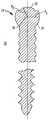
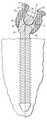
Translated fromKorean도 1은 본 발명의 특정한 바람직한 실시예에 따른 안정화 조립체용 파스너의 정면도이고,1 is a front view of a fastener for a stabilizing assembly according to a particular preferred embodiment of the present invention,
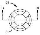
도 2는 도 1에 도시된 파스너의 평면도이고,FIG. 2 is a plan view of the fastener shown in FIG. 1;
도 3a는 도 2의 선 3A-3A를 따라 취한 도 2에 도시된 파스너의 부분적인 횡단면도이고,3A is a partial cross-sectional view of the fastener shown in FIG. 2 taken along line 3A-3A in FIG. 2, FIG.
도 3b는 도 3a에 도시된 파스너의 일부를 확대하여 도시한 도면이고,FIG. 3B is an enlarged view of a part of the fastener shown in FIG. 3A;
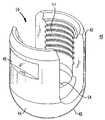
도 4는 본 발명의 특정한 바람직한 실시예에 따른 안정화 조립체용 결합 요소의 사시도이고,4 is a perspective view of a coupling element for a stabilizing assembly according to a particular preferred embodiment of the invention,
도 5는 도 4에 도시된 결합 요소의 부분적인 횡단면도이고,FIG. 5 is a partial cross-sectional view of the coupling element shown in FIG. 4,
도 6a 및 도 6b는 본 발명의 특정한 바람직한 실시예에 따른 도 4 및 도 5의 결합 요소와 도 1 내지 도 3b의 파스너를 조립하는 방법을 도시하며,6A and 6B illustrate a method of assembling the fastening elements of FIGS. 1 and 3B with the coupling elements of FIGS. 4 and 5 in accordance with certain preferred embodiments of the present invention.
도 7은 도 6b에 도시된 조립체의 사시도이고,7 is a perspective view of the assembly shown in FIG. 6B,
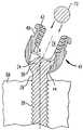
도 8은 본 발명의 특정한 바람직한 실시예에 따라 파스너를 뼈에 박아 넣기 위하여 도 7의 조립체에 결합되는 드라이버의 사시도이고.FIG. 8 is a perspective view of a driver coupled to the assembly of FIG. 7 to drive a fastener into the bone in accordance with certain preferred embodiments of the present invention. FIG.
도 9a는 파스너가 뼈에 고정된 후의 도 7의 조립체를 도시하며,9A shows the assembly of FIG. 7 after the fastener is secured to the bone,
도 9b는 결합 요소가 안정화 로드를 수용하도록 피벗된 상태로 있는 도 9a의 일부의 확대도이고,FIG. 9B is an enlarged view of a portion of FIG. 9A with the coupling element pivoted to receive the stabilizing rod; FIG.
도 9c는 본 발명의 특정한 바람직한 실시예에 따라 안정화 로드가 멈춤 나사에 의해 결합 요소에 고정된 것을 도시하며,9c shows that the stabilizing rod is fixed to the coupling element by a stop screw in accordance with certain preferred embodiments of the present invention,
도 10은 본 발명의 다른 바람직한 실시예에 따른 결합 요소의 횡단면도를 도시한 도면이고,10 shows a cross-sectional view of a coupling element according to another preferred embodiment of the invention,
도 11은 도 10에 도시된 결합 요소의 부분 확대도이고,FIG. 11 is a partially enlarged view of the coupling element shown in FIG. 10;
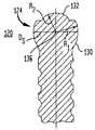
도 12는 본 발명의 특정한 바람직한 실시예에 따른 파스너의 부분도이고,12 is a partial view of a fastener in accordance with certain preferred embodiments of the present invention,
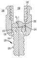
도 13a 및 도 13b는 본 발명의 특정한 바람직한 실시예에 따라 결합 요소에 파스너를 조립하는 방법을 나타내는 도면이고,13A and 13B illustrate a method of assembling a fastener to a coupling element in accordance with certain preferred embodiments of the present invention,
도 14는 본 발명의 추가의 바람직한 실시예에 따른 결합 요소의 사시도이고,14 is a perspective view of a coupling element according to a further preferred embodiment of the invention,
도 15는 도 14의 결합 요소의 정면도이고,15 is a front view of the coupling element of FIG. 14,
도 16은 도 14 및 도 15에 도시된 결합 요소의 평면도이고,16 is a plan view of the coupling element shown in FIGS. 14 and 15,
도 17은 본 발명의 추가의 바람직한 실시예에 따라 결합 요소와 결합된 나사식 파스너의 정면도이고,17 is a front view of a threaded fastener engaged with a coupling element according to a further preferred embodiment of the present invention,
도 18은 본 발명의 추가의 바람직한 실시예에 따른 안정화 조립체용 파스너를 도시한 도면이다.18 shows a fastener for a stabilizing assembly according to a further preferred embodiment of the present invention.
〈도면의 주요 부분에 대한 부호의 설명〉<Explanation of symbols for main parts of drawing>
20 : 파스너20: fastener
24 : 나사 헤드24: screw head
26 : 나사26: screw
28 : 네크28 neck
34 : 홈34: home
40 : 결합 요소40: coupling element
48 : 홈48: home
50 : 보어50: bore
52 : 공동52: joint
62 : 드라이버62: driver
72 : 안정화 로드72: stabilization rod
본 발명은 척추 고정 기구에 관한 것으로, 보다 구체적으로 말하면 조립체를 구속하기 위하여 개선된 나사 헤드/결합 요소 계면을 갖춘 낮은 프로파일의 척추경 나사 조립체에 관한 것이다.The present invention relates to a spinal fixation mechanism, and more particularly to a low profile pedicle screw assembly with an improved screw head / coupling element interface for constraining the assembly.
척주(脊柱)는, 신체에 지지부를 제공하고 섬세한 척수와 척수 신경을 보호하는 뼈의 연결 조직의 고도로 복잡한 시스템이다. 척주는 하나의 위에 다른 하나가 적층되는 일련의 척추뼈를 포함하며, 각 척추뼈 본체는 비교적 약한 해면뼈로 이루어진 내부 또는 중앙부와 비교적 강한 피질성 뼈로 이루어진 외부를 포함한다. 각 척추뼈 본체 사이에는 척주가 겪는 압축력을 완화 및 완충하는 추간 원판이 위치한다. 척수와 척수 신경을 포함하는 척추관은 척주뼈 본체의 배후에 위치한다.The spinal column is a highly complex system of connective tissue of bone that provides support to the body and protects the delicate spinal cord and spinal nerves. The spinal column comprises a series of vertebrae that are stacked one on top of the other, and each vertebral body includes an interior or center of relatively weak sponges and an exterior of relatively strong cortical bone. Between each vertebral body is an intervertebral disc that relaxes and cushions the compressive force experienced by the spinal column. The spinal canal, including the spinal cord and spinal nerves, is located behind the spinal column.
척주 측만증(척주의 비정상적인 측방향 만곡), 척주 후만증(일반적으로 흉추에서의 척주의 비정상적인 전방 만곡), 과도한 척주 전만증(일반적으로 요추에서의 척주의 비정상적인 후방 만곡), 척추뼈 전전위증(일반적으로 요추 또는 경추에서 하나의 척추뼈가 다른 척추뼈 위로 전방 이동하는 것), 및 디스크의 파열 또는 골절, 퇴행성 디스크 질환, 척추뼈의 골절과 같은 외상, 질병 또는 비정상(abnormality)에 의해 야기되는 기타 장애를 포함한 많은 종류의 척주 장애가 존재한다. 그러한 증상으로 고통받는 환자는 일반적으로 극도의 고통 및 약화된 고통 뿐 아니라, 저하된 신경 기능을 경험하게 된다.Spinal scoliosis (abnormal lateral curvature of the spine), spinal sclerosis (usually abnormal anterior curvature of the spine in the thoracic spine), excessive spinal lordosis (usually abnormal posterior curvature of the spine in the lumbar spine), vertebral dislocation (usually lumbar spine) Or forward movement of one vertebrae over the other vertebrae in the cervical spine) and other disorders caused by trauma, disease or abnormality such as disc rupture or fracture, degenerative disc disease, fracture of the vertebrae There are many types of spinal disorders, including. Patients suffering from such symptoms generally experience extreme neurological distress as well as extreme pain and weakened pain.
일반적으로, 본 발명은 통상적으로 척추 고정(spinal fixation)으로 지칭하는 기술을 포함하므로, 척추의 척추뼈를 함께 융합시키거나 및/또는 기계적으로 고정하는 데 외과적인 삽임물(implant)이 사용된다. 척추 고정은 척추의 전체적인 배열을 변경하도록 인접 척추뼈의 정렬을 서로에 대하여 변경시키는 데도 사용될 수 있다. 이러한 기술은 전술한 증상을 치료하여, 대부분의 경우에 환자가 겪는 고통을 경감시키는 데 효과적으로 이용되어 왔다. 그러나, 이하에 보다 상세하게 설명하는 바와 같이, 현재의 척주 고정 기구와 관련한 몇 가지 단점이 있다.In general, the present invention includes a technique commonly referred to as spinal fixation, so surgical implants are used to fuse and / or mechanically fix the vertebrae of the spine together. Spinal fixation can also be used to alter the alignment of adjacent vertebrae relative to one another to alter the overall arrangement of the spine. This technique has been used effectively to treat the aforementioned symptoms and in most cases alleviate the pain experienced by the patient. However, as described in more detail below, there are some disadvantages associated with current spinal column anchorages.
한 가지 척주 고정 기술에는, 척추에 대략 평행하게 연장되고 통상적으로 척추 로드(spine rod)로 지칭되는 정형외과용 로드를 이용하여 척추를 고정하는 것이 수반된다. 이는 척주를 후부로 노출시키고 적절한 척추뼈의 척추경(pedicle)에 뼈 나사를 조임으로써 달성될 수 있다. 척추경 나사는 일반적으로 척추뼈마다 2개가 설치되어, 척추 로드에 대한 고정점으로서 작용한다. 따라서, 관통되어 척추 로드 를 수용하게 되어 있는 결합 요소는 척추 로드를 나사에 결합하는 데 사용된다. 로드의 정렬의 영향으로 척추는 보다 유리한 형상으로 맞춰지게 된다. 일정한 경우에, 척추 로드는 척주의 원하는 만곡을 달성하도록 구부러질 수 있다.One spinal column fixation technique involves securing the spine using an orthopedic rod that extends approximately parallel to the spine and is commonly referred to as a spine rod. This can be accomplished by exposing the spinal column to the back and tightening the bone screws to the pedicle of the appropriate vertebrae. Pedicle screws are generally two per vertebrae, acting as anchor points for the vertebral rods. Thus, a coupling element penetrated to receive the spinal rod is used to couple the spinal rod to the screw. Under the influence of the alignment of the rods the vertebrae are adapted to a more advantageous shape. In some cases, the spinal rod can be bent to achieve the desired curvature of the spinal column.
Vignaud 등의 미국 특허 제5,129,388호는 나사의 상단에 강하게 연결된 U자형 헤드가 있는 척추경 나사를 구비하는 척추 고정 기구를 개시하고 있다. U자형 헤드는 내부에 척추 로드를 수용하도록 U자형 채널을 형성하는 2개의 아암을 포함한다. U자형 헤드에는 수나사가 형성된 멈춤 나사가 그 안에 나사 결합될 수 있도록 암나사가 형성되어 있다. 척추경 나사가 뼈에 삽입되고 척추 로드가 U자형 채널 내에 위치한 후에, 멈춤 나사는 U자형 채널의 암나사에 나사 결합되어 척추 로드를 채널 내에 고정하고 척추 로드와 척추경 나사 사이의 상대 운동을 막는다. 고정 기구는 U자형 헤드의 상부를 덮는 캡도 포함하여, 멈춤 나사가 U자형 헤드의 암나사에 나사 결합되는 때에 아암이 벌어지는 것을 방지한다.U. S. Patent No. 5,129, 388 to Vignaud et al. Discloses a spinal fixation mechanism having a pedicle screw with a U-shaped head strongly connected to the top of the screw. The U-shaped head includes two arms that form a U-shaped channel therein to receive a spinal rod. The U-shaped head is formed with a female thread so that the male threaded set screw can be screwed therein. After the pedicle screw is inserted into the bone and the spinal rod is located in the U-shaped channel, the stop screw is screwed into the female thread of the U-shaped channel to secure the spinal rod in the channel and prevent the relative movement between the spinal rod and the pedicle screw. The fastening mechanism also includes a cap covering the top of the U-shaped head, to prevent the arm from opening when the stop screw is screwed into the female thread of the U-shaped head.
외과 의사들은 전술한 '388 특허에 개시된 것과 같은 척추 고정 기구를 삽입하고자 할 때에 상당한 어려움에 직면해 왔다. 이는 나사를 수용하는 척추경의 상이한 방향성(orientation)과 척추의 만곡에 기인하여 인접 나사의 U자형 헤드가 종종 서로 정렬이 어긋나기 때문이다. 그 결과로서, 척추 로드는 로드가 인접 U자형 채널을 통과하도록 종종 복수의 평면에서 만곡되어야 한다. 이들 문제는 조립체의 강도를 약화시키고, 상당히 장시간의 작업을 야기하므로, 수술과 관련한 합병증의 가능성을 증가시킨다.Surgeons have faced significant difficulties when attempting to insert spinal fixation instruments, such as those disclosed in the aforementioned '388 patent. This is because the U-shaped heads of adjacent screws are often out of alignment with each other due to the different orientation of the pedicle that receives the screws and the curvature of the spine. As a result, the spinal rod must often be curved in a plurality of planes such that the rod passes through adjacent U-shaped channels. These problems weaken the strength of the assembly and lead to significantly longer work, thus increasing the likelihood of complications associated with surgery.
전술한 문제에 따라서, Errico 등의 미국 특허 제5,733,286호와, Biedermann 등의 미국 특허 제5,672,176호와, Metz-Stavenhagen 등의 미국 특허 제5,476,464호는 다축의 척추 고정 기구를 개시하고 있으며, 여기서 뼈에 고정된 고정 요소는 구형 헤드를 갖추고 있다. 전술한 특허의 고정 기구는 정형외과용 로드 구속 조립체도 갖추는데, 이 조립체는 그 안에 정형외과용 로드를 고정하고 이 로드를 고정 요소와 연결하기 위한 것이다. 고정 요소의 구형 헤드는 정형외과용 로드 구속 조립체에 대한 고정 요소의 운동을 허용한다. 그러나, 전술한 특허는 전술한 Vignaud의 '388 특허에 개시된 것과 같은 고정 기구의 모든 결점을 해결하지는 못하는데, 이는 각 척추 고정 기구가 후속하는 삽입에 따라 변위될 수 있기 때문이다. 이는 주로 고정 요소의 구형 헤드와 로드 구속 조립체 사이의 불충분한 표면적 접촉에 기인한 것이다. 또한, 상기 기구는 복잡하고, 많은 부품을 포함하며, 제조하기 어렵다.In accordance with the foregoing problem, US Pat. No. 5,733,286 to Errico et al., US Pat. No. 5,672,176 to Biedermann et al., And US Pat. No. 5,476,464 to Metz-Stavenhagen et al. Disclose multiaxial spinal fixators The fixed stationary element has a spherical head. The fastening mechanism of the aforementioned patent also has an orthopedic rod restraint assembly, which is for fixing the orthopedic rod therein and connecting the rod with the fastening element. The spherical head of the securing element allows the movement of the securing element relative to the orthopedic rod restraint assembly. However, the above patent does not address all the shortcomings of the fasteners as disclosed in the aforementioned Vignaud's' 388 patent, since each spinal fixator can be displaced with subsequent insertion. This is mainly due to insufficient surface area contact between the spherical head of the fastening element and the rod restraint assembly. In addition, the apparatus is complex, contains many parts, and is difficult to manufacture.
1999년 10월 7일자의 공동 양도된 미국 특허 출원 제09/414,272호의 특정한 바람직한 실시예에서, 척추경 나사 조립체는 뼈에 삽입되는 첨단과 그 반대측 단부에 있는 확장 가능한 헤드를 갖춘 파스너를 포함하는데, 이 특허의 개시 내용은 본원 명세서에 전체적으로 참고로 인용된다. 확장 가능한 헤드는 볼록부가 있는 외면과, 내면이 있고 내부 치수를 정하는 오목부와, 헤드의 팽창을 허용하도록 그 내면과 외면 사이에서 연장되는 하나 이상의 슬롯을 포함한다. 조립체는 적어도 부분적으로 상기 오목부 내에서 위치할 수 있는 삽입물(insert)도 포함하는데, 이 삽입물은 외면을 갖추고 있으며, 오목부의 내부 치수보다 큰 외부 치수를 정하는 것이다다. 조립체에는 결합 요소가 포함되며, 이 결합 요소는 로드 수용 개구와, 파 스너를 수용하기 위한 보어와, 파스너의 헤드를 수용하기 위한 시트를 포함하는데, 이 시트는 헤드의 볼록한 하측을 수용하기 위한 오목부를 포함하여, 파스너가 이 시트에 구속되기 전에 결합 요소에 대하여 선회 및 회전될 수 있게 한다. 정형외과용 로드가 결합 요소 내에 위치한 후에, 결합 요소와 결합되는 구속 요소는 정형외과용 로드를 로드 수용 개구에 구속한다. 고정 요소는 로드 수용 개구 내에 배치된 정형외과용 로드에 대하여 압박되게 되어 있으며, 그에 따라 삽입물을 확장 가능한 헤드의 오목부로 압박하여, 삽입물의 외부 치수는 헤드의 내부 치수에 대하여 지지되므로, 헤드의 외면이 결합 요소의 오목한 시트에 대하여 확장하여 파스너가 결합 요소에 대하여 추가로 선회 운동하는 것이 방지된다. 다른 바람직한 실시예에서, 헤드는 탄소 섬유와 같은 소재로 제조되어 확장성이 있다.In certain preferred embodiments of commonly assigned US patent application Ser. No. 09 / 414,272, filed October 7, 1999, the pedicle screw assembly includes a fastener with an expandable head at the tip and opposite end thereof inserted into the bone, The disclosures of this patent are incorporated herein by reference in their entirety. The expandable head includes an outer surface with convex portions, an inner and inner dimensioned recess, and one or more slots extending between the inner and outer surfaces to allow for expansion of the head. The assembly also includes an insert, which can be at least partially located within the recess, which has an outer surface and defines an outer dimension that is greater than the inner dimension of the recess. The assembly includes a coupling element, the coupling element including a rod receiving opening, a bore for receiving the fastener, and a sheet for receiving the head of the fastener, the sheet being recessed to receive the convex lower side of the head. A portion to allow the fastener to be pivoted and rotated relative to the engagement element before it is constrained to this sheet. After the orthopedic rod is located in the engaging element, the restraining element engaged with the engaging element constrains the orthopedic rod to the rod receiving opening. The securing element is adapted to press against an orthopedic rod disposed within the rod receiving opening, thereby pressing the insert into the recess of the expandable head so that the external dimension of the insert is supported against the internal dimension of the head, Expansion against the concave sheet of this engagement element prevents the fastener from further pivoting relative to the engagement element. In another preferred embodiment, the head is made of a material such as carbon fiber and is expandable.
전술한 기구에도 불구하고, 종래 기술의 척추 고정 기구의 개선에 대한 여지가 남아 있는데, 즉 나사 헤드의 구속 방식, 사용하는 데 있어서의 복잡성, 정형외과용 로드와 로드 구속 조립체를 적절하게 배치하는 데에 있어서의 곤란함, 일부 복잡한 기구에 결합되는 많은 부품에 요구되는 조작성, 및 둘 사이의 취약한 계면에 기인하여 뼈 고정 요소에 대한 로드 구속 조립체의 수술 후의 운동 등의 문제가 여전히 존재한다.Notwithstanding the instruments described above, there remains room for improvement of the prior art spinal fixation mechanisms, namely the screw head restraint method, the complexity of use, the proper placement of orthopedic rods and rod restraint assemblies. Problems still exist, such as difficulties in operation, maneuverability required for many components coupled to some complex instruments, and post-operative movement of the rod restraint assembly relative to the bone fixation element due to the fragile interface between the two.
본 발명의 특정의 바람직한 실시예에 따르면, 척주를 안정화하는 데 사용되는 안정화 조립체는, 상단과, 상단에 있는 헤드와, 그 상단과 하단 사이에서 연장 되는 하나 이상의 고정 요소를 갖추고 있는 파스너를 포함한다. 파스너의 헤드는, 중심과, 반경 방향 제1 표면이 있는 하측부와, 반경 방향 제2 표면이 있는 상측부를 포함하며, 반경 방향 제1 표면은 상기 헤드의 중심으로부터의 제1 반경을 정하고, 반경 방향 제2 표면은 헤드의 중심으로부터의 제2 반경을 정하며, 상기 제1 반경은 제2 반경보다 크다. 본 발명은 어떠한 특정 작동 원리에 한정되는 것은 아니지만, 이중 반경의 외면을 갖는 파스너 헤드를 이용하는 것이 전체 윤곽이 낮은 안정화 조립체를 제공하고, 그에 의해 조립체의 치밀함을 증진시키는 것으로 여겨진다. 낮은 윤곽은, 부분적으로는, 헤드 상부에서 반경 방향 제2 표면의 높이가 낮아짐으로 인한 것이다.According to certain preferred embodiments of the invention, a stabilizing assembly used to stabilize the spinal column comprises a fastener having a top, a head at the top, and one or more fastening elements extending between the top and the bottom. . The head of the fastener comprises a center, a lower side with a radial first surface, and an upper side with a radial second surface, the radial first surface defining a first radius from the center of the head, the radius The directional second surface defines a second radius from the center of the head, the first radius being greater than the second radius. Although the present invention is not limited to any particular principle of operation, it is believed that using a fastener head having a double radius outer surface provides a stabilized assembly with low overall contour, thereby enhancing the compactness of the assembly. The low profile is partly due to the lower height of the radial second surface at the top of the head.
척추경 나사 조립체는 결합 요소 내에 삽입되는 안정화 로드와 파스너를 함께 결합하는 결합 요소도 포함하는 것이 바람직하다. 결합 요소는 상단 및 하단과, 안정화 로드를 수용하게 되어 있는 로드 수용 개구와, 상기 파스너를 수용하도록 결합 요소의 하단을 통하여 연장되는 보어와, 파스너가 보어 내에 위치할 때 헤드의 반경 방향 제1 표면에 맞물리게 되는 결합 요소의 하단에 인접한 시트를 포함하는 것이 바람직하다. 특정의 바람직한 실시예에 있어서, 시트는 결합 요소의 하단을 향하여 내향으로 테이퍼지는 측벽을 갖는 원추형 시트이다. 특정의 바람직한 실시예에 있어서, 로드 수용 개구는 결합 요소의 상단에서 시작하여 결합 요소의 하단을 향하여 연장되며, 로드 수용 개구의 하단은 결합 요소의 양측에서 U자형 채널에서 종단되는 것이 바람직하다.The pedicle screw assembly preferably also includes a coupling element for coupling together the stabilizing rod and the fastener inserted into the coupling element. The coupling element has a top and a bottom, a rod receiving opening adapted to receive the stabilizing rod, a bore extending through the bottom of the coupling element to receive the fastener, and a radial first surface of the head when the fastener is located in the bore. It is preferred to include a sheet adjacent the bottom of the coupling element to be engaged with. In certain preferred embodiments, the sheet is a conical sheet having sidewalls that taper inwardly towards the bottom of the coupling element. In certain preferred embodiments, the rod receiving opening extends from the top of the coupling element toward the bottom of the coupling element, and the bottom of the rod receiving opening preferably terminates in a U-shaped channel on both sides of the coupling element.
안정화 조립체는 결합 요소와 결합되는 구속 요소도 포함하는 것이 바람직한 데, 이 구속 요소는 로드 수용 개구 내에 위치하는 안정화 로드에 힘을 가하게 되며, 이로써 안정화 로드는 헤드의 반경 방향 제2 표면에 힘을 가하여 헤드의 반경 방향 제1 표면을 원추형 시트에 대하여 압박하여 파스너와 결합 요소의 서로에 대한 추가의 선회 및 회전 이동을 방지한다. 구속 요소는 결합 요소의 암나사와 나사 결합되도록 수나사를 갖춘 멈춤 나사를 포함할 수 있다. 그러나, 다른 실시예에 있어서, 결합 요소는 그 외면에 수나사가 형성되는 것이 바람직하고, 구속 요소는 결합 요소의 수나사에 나사 결합되는 암나사가 있는 너트를 포함한다.The stabilizing assembly preferably also includes a restraining element that engages the engaging element, which restrains the stabilizing rod located in the rod receiving opening, whereby the stabilizing rod exerts a force on the radial second surface of the head. The radial first surface of the head is pressed against the conical sheet to prevent further pivoting and rotational movement of the fastener and engaging element relative to each other. The restraint element may comprise a set screw with a male thread to thread the female thread of the coupling element. However, in another embodiment, the coupling element preferably has a male thread on its outer surface, and the restraint element comprises a nut with a female thread that is screwed into the male thread of the coupling element.
특정의 바람직한 실시예에 있어서, 파스너는 그 상단과 하단 사이에서 연장되는 종방향 축선을 갖는 나사식 파스너로서, 나사 헤드의 상측으로부터 그것의 하측을 향하여 연장되는 적어도 하나의 홈이 있는 나사 헤드를 포함하며, 상기 적어도 하나의 홈은 파스너를 뼈에 삽입하기 위한 드라이버를 수용하게 되어 있다. 상기 적어도 하나의 홈은 파스너의 종방향 축선과 실질적으로 평행한 방향으로 연장되는 것이 바람직하다. 또한, 상기 적어도 하나의 홈은 헤드의 둘레에서 서로 동일 간격을 두고 있는 복수의 홈을 포함하는 것이 유리하다. 파스너는 결합 요소와 파스너가 서로데 대하여 용이하게 선회 운동하도록 감소된 직경의 네크부도 포함하는 것이 바람직하다. 파스너의 네크는 결합 요소에 대한 파스너의 선회 범위를 확장시키도록 오목면을 포함할 수도 있다.In a particular preferred embodiment, the fastener is a threaded fastener having a longitudinal axis extending between its top and bottom ends, the fastener comprising at least one grooved screw head extending from the top of the screw head toward its bottom. The at least one groove is adapted to receive a driver for inserting the fastener into the bone. The at least one groove preferably extends in a direction substantially parallel to the longitudinal axis of the fastener. It is also advantageous that the at least one groove comprises a plurality of grooves spaced at equal intervals from each other around the head. The fastener preferably also includes a neck portion of reduced diameter so that the fastening element and the fastener pivot easily relative to each other. The neck of the fastener may comprise a concave surface to extend the fastening range of the fastener relative to the engagement element.
파스너는 샤프트를 갖춘 드라이버를 이용하여 뼈에 삽입될 수 있으며, 이 샤프트는 하단과 이 하단으로부터 연장되는 복수의 첨단을 포함한다. 첨단은 헤드의 홈에 삽입되게 되어 있는 것이 바람직하다. 드라이버의 샤프트는 결합 요소의 암 나사와 맞물리게 되어 있는 수나사를 포함할 수 있다.The fastener can be inserted into the bone using a driver with a shaft, which shaft includes a bottom and a plurality of tips extending from the bottom. The tip is preferably to be inserted into the groove of the head. The shaft of the driver may comprise a male screw adapted to engage the female screw of the coupling element.
작동에 있어서, 결합 요소는 척추뼈와 같은 뼈에 나사식 파스너를 고정함으로써 적소에 고정된다. 파스너가 뼈에 고정되기 전에 뼈에 유도 구멍이 형성될 수 있다. 결합 요소가 적소에 고정된 후에, 바람직하게는 결합 요소의 하단과 뼈 사이에 간격이 남아 있어서, 결합 요소는 파스너 및 뼈에 대하여 자유로이 선회 및 회전한다. 이러한 선회 및 회전 작용으로 인하여 결합 요소의 로드 수용 개구 내에서의 정형외과용 안정화 로드의 배치가 용이해진다.In operation, the engagement element is secured in place by securing a threaded fastener to a bone, such as the vertebrae. Guide holes may be formed in the bone before the fasteners are secured to the bone. After the coupling element is secured in place, there is preferably a gap between the bottom of the coupling element and the bone so that the coupling element is free to pivot and rotate relative to the fastener and the bone. This pivoting and rotating action facilitates the placement of the orthopedic stabilizing rod in the rod receiving opening of the coupling element.
안정화 로드가 결합 요소의 로드 수용 개구 내에 배된 후에, 구속 요소, 즉 수나사가 형성된 멈춤 나사는 결합 요소의 암나사에 나사 결합된다. 멈춤 나사가 조여짐에 따라, 멈춤 나사의 하측은 정형외과용 로드와 맞닿아 로드를 통하여 헤드의 반경 방향 제2 표면에 하향 힘을 가한다. 본원 명세서에 사용된 바와 같이, "하향 힘(downward force)"이라는 용어는 결합 요소의 하단을 지향하는 힘을 의미한다. 헤드의 반경 방향 제2 표면에 가해진 하향 힘은 헤드의 반경 방향 제1 표면을 결합 요소의 원추형 시트로 압박한다. 나사 헤드의 반경 방향 제1 표면과 원추형 시트의 결합으로 인하여, 결합 요소는 나사 헤드에 대하여 고정되므로 결합 요소의 추가의 선회 및 회전 운동은 방지된다. 결과로서, 하나 이상의 뼈 파스너에 대한 척추 로드 또는 결합 요소의 시술후 변위 및/또는 운동의 가능성은 현저하게 감소된다. 따라서, 본 발명은 보다 신뢰성 있는 척추 고정 기구를 제공하고, 종래 기술의 기구에서 나타나는 시술후의 변위 문제를 해결한다. 또한, 본 발명의 척추경 나사 조립체는 보다 적은 수의 부품을 갖는다. 결과로서, 이식 시술은 훨씬 단순 해지고, 부품이 환자의 신체 내측으로 떨어질 가능성은 현저하게 줄어든다.After the stabilizing rod is drained into the rod receiving opening of the coupling element, the restraining element, ie the male threaded stop screw, is screwed into the female thread of the coupling element. As the stop screw is tightened, the lower side of the stop screw abuts against the orthopedic rod and exerts a downward force on the radial second surface of the head through the rod. As used herein, the term "downward force" means a force directed toward the bottom of the coupling element. The downward force exerted on the radial second surface of the head forces the radial first surface of the head onto the conical sheet of the engaging element. Due to the engagement of the conical sheet with the radial first surface of the screw head, the coupling element is fixed relative to the screw head so that further pivoting and rotational movement of the coupling element is prevented. As a result, the likelihood of post-operative displacement and / or movement of the spinal rod or engaging element relative to one or more bone fasteners is significantly reduced. Accordingly, the present invention provides a more reliable spinal fixation mechanism and solves the post-procedure displacement problem seen with the prior art instruments. In addition, the pedicle screw assembly of the present invention has fewer parts. As a result, the implantation procedure is much simpler, and the likelihood of parts falling inside the patient's body is significantly reduced.
특정의 바람직한 실시예에 있어서, 파스너는 Sutter의 미국 특허 제4,484,570호에 개시된 것과 같은 뼈 이식 소재를 수용하도록 내부에 하나 이상의 구멍을 포함할 수 있다. 나사를 뼈에 고정하는 데에 나사를 이용하는 대신에, 다른 바람직한 실시예에서는, 파스너가 전술한 Metz-Stavenhagen의 미국 특허 제5,476,464호에 개시된 것과 같은 후크형 고정 요소를 포함할 수 있다. 파스너는 그 외면에 미늘(barb)이 있는 구조일 수도 있으며, 이로써 파스너는 뼈에 압박되고, 미늘은 파스너가 뼈로부터 빠지는 것을 방지한다.In certain preferred embodiments, the fastener may include one or more holes therein to receive bone graft material, such as disclosed in US Pat. No. 4,484,570 to Sutter. Instead of using the screw to secure the screw to the bone, in another preferred embodiment, the fastener may comprise a hook-type fastening element such as disclosed in U.S. Patent No. 5,476,464 to Metz-Stavenhagen, described above. The fastener may have a barb structure on its outer surface, whereby the fastener is pressed against the bone and the barb prevents the fastener from falling out of the bone.
특정의 바람직한 실시예에 있어서, 파스너 헤드의 상측부는 스크루드라이버 또는 육각 렌치와 같은 드라이버를 수용하게 되어 있는 소켓을 포함할 수 있다. 이 실시예에서, 드라이버를 소켓에 삽입하고, 뒤이어 그 드라이버를 회전시켜 파스너를 시계 방향 또는 반시계 방향으로 회전시킴으로써 파스너가 뼈에 결합된다.In certain preferred embodiments, the upper portion of the fastener head may include a socket adapted to receive a driver, such as a screwdriver or a hexagon wrench. In this embodiment, the fastener is coupled to the bone by inserting the driver into the socket and then rotating the driver to rotate the fastener clockwise or counterclockwise.
결합 요소는 결합 요소 내에 로드를 안착시키기 위한 강제 도구와 같은 제어 장치를 수용하도록 내부에 하나 이상의 오목부(impression) 또는 홈이 있을 수 있다. 일부 실시예에서, 오목부 또는 홈은 일반적으로 결합 요소의 종방향 축선에 대하여 실질적으로 수직한 방향으로 연장된다. 홈 또는 막힌 구멍이 결합 요소의 외면에 형성될 수도 있다.The engagement element may have one or more depressions or grooves therein to receive a control device such as a force tool for seating the rod in the engagement element. In some embodiments, the recesses or grooves generally extend in a direction substantially perpendicular to the longitudinal axis of the coupling element. Grooves or blind holes may be formed in the outer surface of the coupling element.
결합 요소의 내면은 그 하단에서, 헤드 하측의 반경 방향 제1 표면과 맞물리고, 적소에 구속되기 전에 헤드를 결합 요소에 대하여 선회시킬 수 있게 하는 시트를 형성하는 것이 바람직하다. 시트는 결합 요소의 하단에 인접하게 마련되는 것 이 바람직하다. 시트는 원추형 또는 볼록형을 이룰 수 있다. 특히 바람직한 실시예에서, 시트는 원추형 시트이다. 원추형 시트의 벽은 그 하단에서의 벽의 직경이 헤드의 외경보다 작도록 서로를 향해 내측으로 테이퍼지는 것이 바람직하다.The inner surface of the coupling element preferably forms a sheet at its lower end that engages the radially first surface below the head and allows the head to pivot relative to the coupling element before being restrained in place. The sheet is preferably provided adjacent the bottom of the coupling element. The sheets can be conical or convex. In a particularly preferred embodiment, the sheet is a conical sheet. The walls of the conical sheet are preferably tapered inwards towards each other such that the diameter of the wall at the bottom thereof is smaller than the outer diameter of the head.
전술한 안정화 기구의 조립 중에, 헤드의 하측이 결합 요소의 원추형 시트에 인접하게 배치될 때까지 파스너의 일부는 결합 요소의 보어를 통과한다. 척추 고정 시술 중에, 파스너가 뼈에 고정된 후에, 결합 요소는 파스너에 대하여 자유로이 선회하게 유지된다. 또한, 결합 요소의 바닥과 뼈 사이에 간격이 존재하는 것이 바람직한데, 간격의 존재로 인하여 결합 요소의 선회 운동이 용이해진다. 파스너의 나사부의 직경보다 작은 직경의 오목면을 갖는 것이 바람직한 파스너의 네크부는 파스너에 대하여 보다 넓은 각도 범위를 통하여 결합 요소가 선회할 수 있게 한다. 따라서, 척추 로드는 결합 요소의 로드 수용 개구 내에 보다 용이하게 배치될 수 있다. 로드가 로드 수용 개구 내에 배치된 후에, 구속 요소는 결합 요소의 나사에 나사 결합된다. 구속 요소가 로드를 조임에 따라, 로드는 헤드의 반경 방향 제2 표면에 하향 힘을 가한다. 헤드의 반경 방향 제2 표면에 가해진 하향 힘은 헤드의 반경 방향 제1 표면을 결합 요소의 원추형 시트로 압박한다. 원추형 시트와 헤드의 반경 방향 제1 표면의 결합으로 인하여, 결합 요소는 헤드에 대하여 구속되므로, 결합 요소의 추가의 선회 및 회전 운동은 방지된다. 결과로서, 척추경 나사 조립체의 시술 후의 변위 및/또는 이동의 가능성이 크게 줄어서, 척추 이식 환자에게 시술 후의 합병증의 발생이 최소화한다.During assembly of the stabilization mechanism described above, part of the fastener passes through the bore of the coupling element until the lower side of the head is disposed adjacent to the conical sheet of the coupling element. During a spinal fixation procedure, after the fastener is fixed to the bone, the engagement element remains free to pivot about the fastener. It is also preferred that there is a gap between the bottom and the bone of the coupling element, which facilitates the pivoting movement of the coupling element. The neck portion of the fastener, which preferably has a concave surface smaller than the diameter of the thread of the fastener, allows the coupling element to pivot through a wider angular range with respect to the fastener. Thus, the spinal rod can be more easily disposed within the rod receiving opening of the coupling element. After the rod is placed in the rod receiving opening, the restraining element is screwed into the screw of the engaging element. As the restraining element tightens the rod, the rod exerts a downward force on the radial second surface of the head. The downward force exerted on the radial second surface of the head forces the radial first surface of the head onto the conical sheet of the engaging element. Due to the engagement of the conical sheet and the radial first surface of the head, the coupling element is constrained relative to the head, so that further pivoting and rotational movement of the coupling element is prevented. As a result, the possibility of postoperative displacement and / or movement of the pedicle screw assembly is greatly reduced, minimizing the incidence of postoperative procedures in spinal transplant patients.
본 발명은 파스너를 뼈에 고정 또는 결합하기 위한 도구도 포함하는 것이 바 람직하다. 도구는 회전 가능한 샤프트 및 헤드의 홈에 맞물리도록 샤프트의 단부로부터 연장되는 하나 이상의 첨단을 갖는 드라이버인 것이 바람직하다. 바람직한 실시예에 있어서, 드라이버는 파스너의 헤드 내의 각 홈에 대하여 하나의 첨단을 갖는다. 드라이버는 샤프트의 하단에 수나사가 있을 수도 있다. 수나사는 파스너가 뼈에 고정될 때 결합 요소의 암나사에 맞물리게 되어 있는 것이 바람직하다. 드라이버의 수나사와 결합 요소의 암나사의 결합은 파스너가 뼈에 고정될 때 일반적으로 조립체를 안정화시킨다. 구체적으로, 나사의 결합은 파스너를 뼈에 박을 때 결합 요소가 파스너에 대하여 이동하는 것을 방지하므로, 파스너의 설치를 간단하게 한다.The present invention preferably also includes a tool for securing or engaging the fastener to the bone. The tool is preferably a driver having at least one tip extending from the end of the shaft to engage the rotatable shaft and the groove of the head. In a preferred embodiment, the driver has one tip for each groove in the head of the fastener. The driver may have a male thread at the bottom of the shaft. The male thread is preferably engaged with the female thread of the coupling element when the fastener is fixed to the bone. The engagement of the male screw of the driver with the female screw of the coupling element generally stabilizes the assembly when the fastener is secured to the bone. Specifically, the engagement of the screws prevents the coupling elements from moving relative to the fasteners when driving the fasteners into the bone, thus simplifying the installation of the fasteners.
본 발명의 이들 목적 및 다른 목적과, 특징 및 장점은 첨부 도면을 참고로 하여 이하에 설명하는 바람직한 실시예의 상세한 설명으로부터 보다 명백해진다.These and other objects, features and advantages of the present invention will become more apparent from the detailed description of the preferred embodiments described below with reference to the accompanying drawings.
다른 바람직한 실시예에 있어서, 안정화 조립체용의 결합 요소는 상단 및 하단과, 안정화 로드를 수용하게 되어 있는 로드 수용 개구와, 제1 직경의 반경 방향 제1 표면이 있는 헤드를 갖춘 파스너를 수용하도록 상기 결합 요소의 하단을 통하여 연장되는 보어와, 상기 파스너의 헤드의 하측과 맞물리게 되어 있고 상기 결합 요소의 하단에 인접한 시트를 포함한다. 결합 요소는 바람직하게는 그것의 상단으로부터 하단을 향하여 연장되는 나사와, 상기 결합 요소의 시트와 나사 사이에 있는 환형 립을 포함하고, 이로써 상기 환형 립은 헤드의 반경 방향 제1 표면의 제1 직경보다 작은 제2 직경을 갖는다.In another preferred embodiment, the coupling element for the stabilization assembly is adapted to receive a fastener having a top and a bottom, a rod receiving opening adapted to receive the stabilizing rod, and a head having a radially first surface of a first diameter. A bore extending through the bottom of the engagement element and a sheet adapted to engage the lower side of the head of the fastener and adjacent the bottom of the engagement element. The engagement element preferably comprises a screw extending from its top towards the bottom and an annular lip between the seat and the thread of the engagement element, whereby the annular lip is the first diameter of the radial first surface of the head. Have a smaller second diameter.
또 다른 바람직한 실시예에 있어서, 안정화 조립체용 결합 요소는 상단과, 그로부터 멀리 있는 하단과, 안정화 로드를 수용하게 되어 있는 로드 수용 개구를 포함한다. 결합 요소는 외면과, 결합 요소의 하단을 통하여 연장되는 중앙 보어를 이루는 내면을 포함하는 것이 바람직하다. 결합 요소의 하단에 인접한 시트는 유리하게는 파스너의 헤드의 하측에 결합되게 되어 있고, 이로써 결합 요소의 폭이 최소화하도록 결합 요소는 로드 수용 개구와 그 외면 사이에 하나 이상의 절결부를 포함한다. 본 발명이 어느 특정 작동 원리로 한정되는 것은 아니지만, 로드 수용 개구의 가장자리에 절결부를 마련하면 결합 요소의 폭이 감소하므로, 보다 많은 결합 요소가 안정화 로드의 소정의 길이에 걸쳐 끼워질 수 있는 것으로 여겨진다. 절결부는 결합 요소 상의 날카로운 가장자리도 최소화하여, 결합 요소가 환자의 조직을 상하게 하거나 및/또는 수술 장갑을 찢을 가능성을 줄인다.In another preferred embodiment, the coupling element for the stabilizing assembly comprises a top, a bottom far from it, and a rod receiving opening adapted to receive the stabilizing rod. The coupling element preferably comprises an outer surface and an inner surface which forms a central bore extending through the bottom of the coupling element. The sheet adjacent the bottom of the coupling element is advantageously adapted to engage under the head of the fastener, whereby the coupling element comprises one or more cutouts between the rod receiving opening and its outer surface to minimize the width of the coupling element. Although the invention is not limited to any particular principle of operation, the provision of cutouts at the edges of the rod receiving openings reduces the width of the coupling elements, so that more coupling elements can be fitted over a predetermined length of the stabilizing rod. Is considered. The cutout also minimizes the sharp edges on the joining elements, reducing the likelihood that the joining elements will damage the patient's tissue and / or tear the surgical glove.
본 발명의 이들 목적 및 다른 목적과, 특징 및 장점은 첨부 도면을 참고로 하여 이하에 설명되는 바람직한 실시예의 상세한 설명으로부터 보다 명백해진다.These and other objects, features and advantages of the present invention will become more apparent from the following detailed description of the preferred embodiments described below with reference to the accompanying drawings.
본 발명의 바람직한 특정 실시예에 따른 도 1을 참고하면, 척추경 나사 조립체는 뼈에 삽입되는 첨단(22)과 그 상단에 헤드(24)가 있는 나사식 파스너와 같은 파스너(20)를 포함하고 있다. 나사식 파스너(20)는 첨단(22)과 나사 헤드(24) 사이에서 연장되는 수나사(26)를 포함하는 것이 바람직하다. 수나사(26)는 나사 헤드(24)와 수나사(26)의 상단 사이에 위치하는 것이 바람직한 네크(28)에서 종단된다. 네크(28)는 수나사의 직경보다 작은 직경의 오목한 표면을 갖는 것이 유리하다. 감소된 직경의 네크(28)로 인하여, 나사식 파스너(20)는 보다 넓은 이동 범위를 통해 선회 및 회전될 수 있는데, 이는 이하에서 상세하게 설명한다. 수나사(26), 네크(28) 및 나사 헤드(24)를 포함하는 나사식 파스너는, 내구성이 있고 신체에 이식될 수 있는 티타늄 또는 스테인리스 강과 같은 비유기질의 소재로 만들어지는 것이 바람직하다.Referring to FIG. 1, in accordance with certain preferred embodiments of the present invention, a pedicle screw assembly includes a
도 1 및 도 2를 참고하면, 나사 헤드(24)는 양호하게 반경 방향의 제1 표면을 형성하는 하측부(30)와 반경 방향의 제2 표면을 형성하는 상측부(32)를 갖추고 있다. 나사 헤드(24)에는 양호하게 나사식 파스너(20)의 종방향 축선에 실질적으로 평행한 방향으로 연장되는 하나 이상의 홈(34)이 마련되어 있다. 도 2를 참고하면, 바람직한 일실시예에 있어서, 나사 헤드(24)에는, 서로 일정 간격을 두고 나사 헤드(24)의 외주 둘레에서 연장되는 복수의 홈(34)이 마련된다. 나사 헤드(24)의 상측부(32)는 바람직하게는 복수의 홈(34)의 중앙에 있다.Referring to FIGS. 1 and 2, the
도 3a 및 도 3b를 참고하면, 나사 헤드(24)는 중심(36)이 있으므로, 나사 헤드(24)의 하측부(30)는 중심(36)으로부터의 반경이R1인 반경 방향의 제1 표면을 형성한다. 나사 헤드(24)는 중심(36)으로부터의 제2 반경이R2인 반경 방향의 제2 표면을 갖는 상측부(32)를 포함한다. 복수의 홈(34)은 바람직하게는 나사식 파스너를 뼈에 나사 고정하는 데 사용된 드라이버의 첨단(prong)을 수용하게 되어 있으며, 이에 대해서는 이하에서 상세하게 설명한다.3A and 3B, since the
도 4 및 도 5를 참고하면, 척추경 나사 조립체에는 도 1 내지 도 3b에 도시된 나사식 파스너와 정형외과용 안정화 로드를 결합하는 결합 요소(40)도 포함되어 있다. 결합 요소(40)는 티타늄 또는 스테인리스 강과 같은 불활성 소재로 제조되 는 것이 바람직하다. 결합 요소(40)는 상단(42), 하단(44), 및 이들 상단 및 하단 사이에서 연장되는 종방향 축선(C-C)을 갖추고 있다. 결합 요소(40)에는, 바람직하게는 그 하단(44)의 볼록한 표면과 그 상단의 원통형 표면을 갖는 외면(46)이 마련되어 있다. 외면(46)에는, 바람직하게는 정형 외과용 로드를 척추경 나사 조립체에 안착시키는 데 사용되는 강제 수단(persuader instrument)과 같은 고정 요소 또는 도구를 이용하여 결합 요소(40)를 파지 및/또는 조종할 수 있도록 내부에 형성된 하나 이상의 홈(48)이 포함되어 있다. 홈(48)은 바람직하게도 결합 요소(40)의 종방향 축선(C-C)에 실질적으로 수직한 방향으로 연장되어 있다.4 and 5, the pedicle screw assembly also includes a
결합 요소(40)에는 나사식 파스너를 수용하기 위한 보어(50)가 마련되어 있으며, 이 보어는 결합 요소의 종방향 축선(C-C)을 따라 연장되어 있다. 보어(50)는 결합 요소(40)의 내면을 이루며, 결합 요소의 상단(42)으로부터 하단(44)에 인접한 공동(52)을 향하여 연장되는 암나사(51)를 갖추고 있다. 공동(52)의 하단에는 바람직하게는 하단(44)을 향하여 내측으로 테이퍼지는 측벽이 있는 원추형의 시트(54)가 마련되어 있다. 다른 실시예에서, 결합 요소 상의 나사는 수나사일 수도 있다.The
도 6a 및 도 6b는 나사식 파스너(20)와 결합 요소(40)를 조립하는 한 가지 바람직한 방법을 도시한다. 도 6a를 참고하면, 나사식 파스너(20)의 첨단(22)은 결합 요소의 상단(42)으로부터 하단(44)을 향하여 결합 요소(40)의 보어(50)를 통과하여, 나사식 파스너의 나사부가 보어(50)를 통과한다. 나사식 파스너(20)의 나사부(26)는 보어(50)를 자유로이 통과할 수 있는데, 이는 나사부(26)가 결합 요소(40)의 암나사(51)의 내경보다 작은 외경을 갖기 때문이다. 도 6b를 참고하면, 나사식 파스너(20)는, 나사 헤드(24)가 결합 요소(40)의 공동(52) 내에 배치되고 나사 헤드의 하측이 결합 요소의 시트와 맞물릴 때까지 결합 요소(40)의 하단을 향하여 계속해서 삽입된다.6A and 6B illustrate one preferred method of assembling the threaded
도 7을 참고하면, 나사식 파스너(20)가 결합 요소(40)와 조립된 후에, 나사식 파스너(20)의 네크(28)는 결합 요소에 대하여 자유로이 선회 및 회전한다. 전술한 바와 같이, 네크(28)는 감소된 직경을 갖는 것이 바람직하고, 나사식 파스너(20)와 결합 요소가 보다 넓은 각도 범위에 걸쳐 서로에 대해 선회할 수 있도록 오목한 외면을 가질 수도 있다.Referring to FIG. 7, after the threaded
나사식 파스너(20)와 결합 요소가 함께 조립된 후에, 서브 조립체는 뼈(60)에 삽입될 준비가 된다. 제1 단계에서, 나사식 파스너(20)는 뼈에 유도 구멍(pilot hole)을 천공함으로써 뼈(60)에 고정될 수 있다. 다음에, 나사식 파스너(20)의 첨단(도시 생략)이 유도 구멍에 배치되어, 드라이버 또는 공구를 이용하여 나사식 파스너가 뼈(60)에 나사 결합될 수 있다. 나사식 파스너(20)를 뼈(60)에 박기 위한 하나의 바람직한 드라이버(62)에는 복수의 하향 연장 첨단(68)을 갖춘 하단(66)이 있는 회전 샤프트(64)가 포함되어 있다. 첨단(68)은 나사식 파스너(20)에 있는 나사 헤드(도시 생략)의 홈(34)에 끼워지도록 크기가 정해진다. 샤프트(64)의 회전 시에, 첨단(60)은 나사식 파스너(20)의 홈(34)에 맞물려서 나사식 파스너(20)를 회전시켜 파스너를 뼈(60)에 나사 결합시킨다. 드라이버(62)는, 바람직하게는 샤프트(64)와 첨단(68)의 사이에 수나사(70)를 포함할 수도 있다. 수나사(70)는 결합 요소(40)의 암나사(51; 도 4 및 도 5 참조)와 나사식으로 맞물리도록 설계된다. 드라이버(62)의 수나사(70)와 결합 요소(40)의 암나사(51) 사이의 맞물림 결합은 일반적으로 나사식 파스너(20)를 뼈(60)에 박아 넣을 때 척추경 나사 조립체를 안정화한다.After the threaded
도 9a 및 도 9b를 참고로 하면, 나사식 파스너(20)가 뼈(60)에 고정된 후에, 결합 요소(40)는 나사식 파스너에 대하여 자유로이 선회 및 회전할 수 있게 유지되어 정형외과용 안정화 로드(72)가 결합 요소(40)의 로드 수용 개구(74) 내에서 배치될 수 있다. 로드 수용 개구(74)는 바람직하게는 결합 요소(40)의 상단(42)으로부터 연장되는 U자형 개구를 포함하고 있다. 또한, 나사식 파스너가 뼈에 완전히 삽입된 후에, 결합 요소(40)의 하단(44)과 뼈(60) 사이에는 간격이 존재한다. 이 간격으로 인하여, 결합 요소(40)는 나사식 파스너(20)에 대하여 용이하게 선회 및 회전하게 된다. 다음에, 결합 요소(40)는 홈(48)과 공구를 맞물리게 함으로써 또는 결합 요소의 외측 본체부를 파지함으로써 이동(예컨대, 선회)할 수 있다. 다음에, 결합 요소(40)는 정형외과용 로드(72)가 도 9b에 도시된 바와 같이 로드 수용 개구(74) 내에 배치될 수 있도록 선회 및/또는 회전될 수 있다.9A and 9B, after the threaded
도 9c를 참고하면, 안정화 로드(72)가 결합 요소(40) 내에 배치된 후에, 수나사(도시 생략)가 있는 멈춤 나사(76)는 결합 요소(40)의 암나사(51)에 나사 결합된다. 멈춤 나사(76)는 멈춤 나사(76)의 하측부(78)가 안정화 로드(72)에 맞닿을 때까지 암나사(51)에 계속해서 나사 결합된다. 다음에, 멈춤 나사(76)는 안정화 로드(72)를 로드 수용 채널(74) 내에 고정하도록 암나사(51) 내에서 더욱 회전한 다. 조여진 멈춤 나사(76)는 로드(72)를 통하여 나사 헤드(24)의 상측부(32)의 반경 방향 제2 표면에 하향 힘을 가한다. 나사 헤드(24)의 반경 방향 제2 표면에 가해진 하향 힘은 나사 헤드(24)의 하측부(30)의 반경 방향 제1 표면을 결합 요소(40)의 원추형 시트(54)로 압박한다. 나사 헤드(24)의 하측부(30)의 반경 방향 제1 표면과 원추형 시트(54)의 맞물림으로 인하여, 결합 요소(40)를 나사 헤드(24)에 대하여 고정하는 구형 표면/원추형 표면의 마찰식 고정이 이루어지고, 이로써 결합 요소(40)와 나사식 파스너(20)는 서로에 대하여 추가로 선회 및 회전하는 것이 방지된다. 본 발명은 어떠한 특정 작동 원리에 의해서도 한정되지 않지만, 나사 헤드의 구형 표면과 결합 요소의 원추형 시트의 맞물림은, 나사 헤드와 결합 요소의 계면에 가해지는 고정력(locking force)을 현저하게 증대시키는 것으로 생각된다.Referring to FIG. 9C, after the stabilizing
도 10을 참고하면, 본 발명의 다른 바람직한 실시예에 따라서, 안정화 조립체용 결합 요소(140)는 상단(142)과 하단(144)을 포함하고 있다. 결합 요소(140)는 상단(142)과 하단(144) 사이에서 연장되는 외면(146)도 포함하며, 이 외면(146)은 하나 이상의 홈(148)을 포함하고 있다. 결합 요소는 중앙에 위치된 보어(150)도 포함하며, 이 보어는 종방향 축선(C-C)을 따라 상단(142)과 하단(144) 사이에서 연장되어 있다. 보어(150)는 상단(142)으로부터 하단(144)을 향해 연장되는 암나사(151)에 의해 에워싸여 있다. 결합 요소(140)에는 하단(144)에 인접한 공동(152)도 포함되며, 이 공동은 결합 요소(140)의 하단(144)을 향하여 내측으로 테이퍼진 측벽이 있는 원추형 시트(154)를 포함하고 있다. 결합 요소(140)는 암나 사(151)와 공동(152) 사이의 직경DW를 갖는 내벽(153)과, 내벽(153)과 공동(152) 사이의 립(155)도 포함한다. 립(155)의 직경(DL)은 내벽(153)의 직경(DW)보다 작다. 도 12에 도시된 바와 같이, 나사 헤드(124)의 반경 방향 제1 표면(130)의 외경(DS)은 결합 요소의 립(155)의 직경(DL)보다 크다. 그 결과로, 립(155)은, 파스너(120)의 나사 헤드가 결합 요소(140)와 조립된 후에 결합 요소(140)의 공동(152) 내에 파스너(120)를 유지하는 정지구로서 기능한다.Referring to FIG. 10, in accordance with another preferred embodiment of the present invention, the
도 11은 도 10에 도시된 결합 요소(140)의 일부를 확대한 도면이다. 전술한 바와 같이, 결합 요소(140)는 그 상단(도시 생략)으로부터 하단(144)을 향하여 연장되는 보어(150)와, 암나사(151)와 공동(152) 사이에서 연장되는 내벽(153)을 포함한다. 공동(152)은 내측으로 테이퍼진 측벽이 있는 원추형 시트(154)를 포함한다. 결합 요소(140)는 내벽(153)과 공동(152) 사이에서 위치된 립(155)을 포함한다. 립(155)의 직경(DL)은 결합 요소(140)의 내벽(153)의 직경(DW)보다 작다.FIG. 11 is an enlarged view of a portion of the
도 12는 그 상단에 나사 헤드(124)가 있는 나사식 파스너(120)를 도시하는데, 나사 헤드(124)는 그 하측에 반경 방향 제1 표면(130)과, 그 상측부에 반경 방향 제2 표면(132)을 포함하고 있다. 나사 헤드(124)는 중심(136)과, 중심(136)으로부터의 반경이R1인 반경 방향 제1 표면(130)과 중심(136)으로부터의 반경이R2인 반경 방향 제2 표면(132)을 포함하는데, 여기서R1이R2보다 크다. 나사 헤드(124)의 반경 방향 제1 표면은 길이 R1의 2배의 외경(D2)을 형성한다.FIG. 12 shows a threaded
도 13a 및 도 13b는 도 10 및 도 11에 도시된 결합 요소(140)와 조립되는 나사식 파스너(120)를 도시하고 있다. 전술한 바와 같이, 결합 요소(140)는 나사 헤드(124)의 반경 방향 제1 표면(130)의 직경(DS)보다 작은 직경(DL)을 갖는 립(155)을 포함하지만, 나사 헤드(124)의 반경 방향 제1 표면(130)의 외경(DS)은 내벽(153)의 내경보다 작다.13A and 13B show a threaded
도 13a 및 도 13b를 참고하면, 나사식 파스너(120)를 결합 요소(140)에 조립하는 중에, 나사식 파스너(120)는 나사부(126)가 결합 요소(140) 하단(144)의 개구를 통과하도록 보어(150)를 통과한다. 나사 헤드(124)의 외경(DS)이 내벽(153)의 내경보다 작기 때문에, 나사 헤드(124)는 반경 방향 제1 표면(130)이 립(155)과 맞물릴 때까지 쉽게 보어(150)를 통과한다. 립(155)의 내경(DL)이 나사 헤드(124)의 반경 방향 제1 표면(130)의 외경(DS)보다 작기 때문에, 립(155)은 정지부로서 작용하여, 나사 헤드는 감소된 직경의 립(155)을 밀고 나가야 한다. 도 13b를 참고하면, 나사 헤드(124)의 외경(DS)이 립(155)을 통과한 후에, 나사 헤드는 립(155)에 의하여 공동(152) 내에 유지되며, 결합 요소(140)는 안정화 로드를 수용하도록 나사 헤드(124)에 대하여 선회될 수 있다. 안정화 로드가 결합 요소(140)의 U자형 개구 내에 수용된 후에, 멈춤 나사(도시 생략)는 안정화 로드를 U자형 개구 내에 잡아두도록 결합 요소(140)의 암나사(151)에 나사 결합될 수 있다. 다음에, 멈춤 나사는 안정화 로드에 하향 힘을 가하도록 조여지고, 뒤이어 이 로드는 나사 헤드(124)의 반경 방향 제2 표면(132)에 힘을 가하는 것이 바람직하다. 반경 방향 제2 표면(132) 상의 하향 힘은 결합 요소의 원추형 시트로 반경 방향 제1 표면(130)을 압박하여 나사 헤드와 결합 요소를 서로에 대하여 고정한다.13A and 13B, while assembling the threaded
도 14 내지 도 16은 본 발명의 추가의 바람직한 실시예에 따른 결합 요소(240)를 도시한다. 결합 요소(240)는 상단(242)과, 하단(244) 및 이들(242, 244) 사이에서 연장되는 외면(246)을 포함하고 있다. 결합 요소(240)의 외면(246)은 그 마주하는 아암에 홈(248)을 포함하고 있다. 결합 요소(240)는 그 상단과 하단 사이에서 연장되는 중앙 보어(150)를 포함한다. 결합 요소(240)는 U자형 로드 수용 개구(174)의 양측에 제1 아암(261A) 및 제2 아암(261B)을 포함하며, 이 U자형 로드 수용 개구는 안정화 로드(도시 생략)를 수용하게 되어 있다. U자형 개구의 가장자리에는 그 내부에 절결부(263)가 형성되어 있다. 절결부(263)가 결합 요소의 프로파일 또는 폭을 감소시키므로, 일련의 결합 요소가 안정화 로드와 결합될 때 다른 결합 요소와의 간섭을 최소화한다. 절결부(263)로 인하여, 결합 요소(240)는 함께 보다 긴밀하게 적층되고 각 척추뼈 위에 고정될 수 있으므로, 척추 분절의 고정(fusion)이 개선된다. 본 발명이 임의의 특정 작동 원리로 한정되는 것은 아니지만, 일부 환자는 비교적 작은 척추뼈를 가져서, 결합 요소를 각 척추골 위에 고정하기가 어려운 것으로 관찰되었다. 그 결과로서, 일부 척추뼈는 안정화 조립체의 일부 섹션이 그 뼈에 부착되지 않을 수 있어서, 척추 분절의 전체 부분이 안정화되지 않기 때문에, 이러한 상황은 척추 분절의 안정화 및 통합에 악영향을 끼칠 수 있다. 또한, 절결부(263)는 결합 요소 상에 날카로운 가장자리가 생기는 것을 최소화하는데, 그러한 가장자리는 환자의 조직(tissue)에 염증을 일으키거나 의사의 수술용 장갑을 찢을 수 있다.14-16 illustrate a
도 17은 나사식 파스너(220)와 조립되는 도 14 내지 도 16의 결합 요소(240)의 정면도를 도시한다. 결합 요소(240)는 멈춤 나사(276)를 수용하기 위한 암나사(도시 생략)를 포함한다. 결합 요소(240)는 그 프로파일을 최소화하고 날카로운 가장자리의 발생을 줄이기 위하여 절결부(263)를 포함하고 있다.17 shows a front view of the
도 18은 본 발명의 다른 실시예에 따른 파스너(320)를 도시한다. 파스너(320)는 중심(336)으로부터의 반경이R1인 반경 방향 제1 표면(330)과 중심(336)으로부터의 반경이R2인 반경 방향 제2 표면(332)이 있는 헤드(324)를 포함한다. 제1 반경(R1)은 제2 반경(R2)보다 크다. 파스너(320)는 파스너를 접합부(도시 생략)에 고정하기 위한 후크(370)를 포함하고 있다.18 illustrates a
본 명세서에서는 특정 실시예를 참고로 하여 본 발명을 설명하였지만, 이들 실시예는 본원 발명의 원리 및 용례의 단지 예시적인 것이다. 그러므로, 예시적인 실시예에 대한 많은 변형예가 있을 수 있으며, 첨부된 청구범위에 의해 한정되는 본원 발명의 사상 및 범위를 벗어나지 않으면서 그외의 구성이 있을 수 있다.Although the invention has been described herein with reference to specific embodiments, these embodiments are merely illustrative of the principles and applications of the invention. Therefore, many modifications may be made to the exemplary embodiments, and other configurations may be made without departing from the spirit and scope of the invention as defined by the appended claims.
본 발명에 따르면, 나사 헤드의 구속 방식, 사용하는 데 있어서의 복잡성, 정형외과용 로드와 로드 구속 조립체를 적절하게 배치하는 데에 있어서의 곤란함, 일부 복잡한 기구에 결합된 많은 부품에 요구되는 조작성, 및 둘 사이의 취약한 계 면에 기인하여 뼈 고정 요소에 대한 로드 구속 조립체의 수술 후의 운동 등의 문제를 해소하는 척추경 나사 조립체가 제공된다.According to the present invention, the screw head restraint method, complexity in use, difficulty in properly arranging orthopedic rods and rod restraint assemblies, and operability required for many parts coupled to some complex mechanisms A pedicle screw assembly is provided that solves problems such as post-operative movement of the rod restraint assembly with respect to the bone fixation element due to the weak interface between the two and the two.
Claims (57)
Translated fromKoreanApplications Claiming Priority (2)
| Application Number | Priority Date | Filing Date | Title |
|---|---|---|---|
| US09/755,846US6488681B2 (en) | 2001-01-05 | 2001-01-05 | Pedicle screw assembly |
| US09/755,846 | 2001-01-05 |
Publications (2)
| Publication Number | Publication Date |
|---|---|
| KR20020057790A KR20020057790A (en) | 2002-07-12 |
| KR100551677B1true KR100551677B1 (en) | 2006-02-13 |
Family
ID=25040890
Family Applications (1)
| Application Number | Title | Priority Date | Filing Date |
|---|---|---|---|
| KR1020010082286AExpired - Fee RelatedKR100551677B1 (en) | 2001-01-05 | 2001-12-21 | Pedicle screw assembly |
Country Status (8)
| Country | Link |
|---|---|
| US (5) | US6488681B2 (en) |
| EP (3) | EP2145595B1 (en) |
| JP (2) | JP2002233532A (en) |
| KR (1) | KR100551677B1 (en) |
| AT (3) | ATE390090T1 (en) |
| AU (1) | AU759914B2 (en) |
| CA (1) | CA2359373C (en) |
| DE (2) | DE60140706D1 (en) |
Families Citing this family (313)
| Publication number | Priority date | Publication date | Assignee | Title |
|---|---|---|---|---|
| EP1244387B1 (en)* | 1999-12-24 | 2005-12-14 | Societe De Fabrication De Materiel Orthopedique Sofamor | Pedicle screws with inclined channels to hold support rods |
| US7833250B2 (en) | 2004-11-10 | 2010-11-16 | Jackson Roger P | Polyaxial bone screw with helically wound capture connection |
| DE10055888C1 (en)* | 2000-11-10 | 2002-04-25 | Biedermann Motech Gmbh | Bone screw, has connector rod receiving part with unsymmetrically arranged end bores |
| US8377100B2 (en) | 2000-12-08 | 2013-02-19 | Roger P. Jackson | Closure for open-headed medical implant |
| US6726689B2 (en) | 2002-09-06 | 2004-04-27 | Roger P. Jackson | Helical interlocking mating guide and advancement structure |
| US6488681B2 (en)* | 2001-01-05 | 2002-12-03 | Stryker Spine S.A. | Pedicle screw assembly |
| FR2822053B1 (en)* | 2001-03-15 | 2003-06-20 | Stryker Spine Sa | ANCHORING MEMBER WITH SAFETY RING FOR SPINAL OSTEOSYNTHESIS SYSTEM |
| US10258382B2 (en) | 2007-01-18 | 2019-04-16 | Roger P. Jackson | Rod-cord dynamic connection assemblies with slidable bone anchor attachment members along the cord |
| US8353932B2 (en) | 2005-09-30 | 2013-01-15 | Jackson Roger P | Polyaxial bone anchor assembly with one-piece closure, pressure insert and plastic elongate member |
| US8292926B2 (en) | 2005-09-30 | 2012-10-23 | Jackson Roger P | Dynamic stabilization connecting member with elastic core and outer sleeve |
| US10729469B2 (en) | 2006-01-09 | 2020-08-04 | Roger P. Jackson | Flexible spinal stabilization assembly with spacer having off-axis core member |
| US7862587B2 (en) | 2004-02-27 | 2011-01-04 | Jackson Roger P | Dynamic stabilization assemblies, tool set and method |
| GB2393189B (en)* | 2001-07-19 | 2005-06-15 | Trikon Holdings Ltd | Depositing a tantalum film |
| US6974460B2 (en) | 2001-09-14 | 2005-12-13 | Stryker Spine | Biased angulation bone fixation assembly |
| DE10157969C1 (en) | 2001-11-27 | 2003-02-06 | Biedermann Motech Gmbh | Element used in spinal and accident surgery comprises a shaft joined to a holding element having a U-shaped recess with two free arms having an internal thread with flanks lying at right angles to the central axis of the holding element |
| US7879075B2 (en) | 2002-02-13 | 2011-02-01 | Zimmer Spine, Inc. | Methods for connecting a longitudinal member to a bone portion |
| US7066937B2 (en)* | 2002-02-13 | 2006-06-27 | Endius Incorporated | Apparatus for connecting a longitudinal member to a bone portion |
| US20030171755A1 (en)* | 2002-03-05 | 2003-09-11 | Moseley Colin F. | Bone screws |
| US11224464B2 (en) | 2002-05-09 | 2022-01-18 | Roger P. Jackson | Threaded closure with inwardly-facing tool engaging concave radiused structures and axial through-aperture |
| US8282673B2 (en) | 2002-09-06 | 2012-10-09 | Jackson Roger P | Anti-splay medical implant closure with multi-surface removal aperture |
| WO2006052796A2 (en) | 2004-11-10 | 2006-05-18 | Jackson Roger P | Helical guide and advancement flange with break-off extensions |
| US8876868B2 (en) | 2002-09-06 | 2014-11-04 | Roger P. Jackson | Helical guide and advancement flange with radially loaded lip |
| US8257402B2 (en) | 2002-09-06 | 2012-09-04 | Jackson Roger P | Closure for rod receiving orthopedic implant having left handed thread removal |
| DE10246386B4 (en) | 2002-10-04 | 2008-08-07 | Biedermann Motech Gmbh | Bone screw, bone fixation device and retaining element |
| AU2003287273C1 (en) | 2002-10-30 | 2010-01-07 | Zimmer Spine, Inc. | Spinal stabilization system insertion and methods |
| US9539012B2 (en) | 2002-10-30 | 2017-01-10 | Zimmer Spine, Inc. | Spinal stabilization systems with quick-connect sleeve assemblies for use in surgical procedures |
| US20060095035A1 (en)* | 2004-11-03 | 2006-05-04 | Jones Robert J | Instruments and methods for reduction of vertebral bodies |
| US20040111088A1 (en)* | 2002-12-06 | 2004-06-10 | Picetti George D. | Multi-rod bone attachment member |
| US7141051B2 (en) | 2003-02-05 | 2006-11-28 | Pioneer Laboratories, Inc. | Low profile spinal fixation system |
| US7621918B2 (en) | 2004-11-23 | 2009-11-24 | Jackson Roger P | Spinal fixation tool set and method |
| US8540753B2 (en)* | 2003-04-09 | 2013-09-24 | Roger P. Jackson | Polyaxial bone screw with uploaded threaded shank and method of assembly and use |
| US6716214B1 (en) | 2003-06-18 | 2004-04-06 | Roger P. Jackson | Polyaxial bone screw with spline capture connection |
| US20050182401A1 (en)* | 2003-05-02 | 2005-08-18 | Timm Jens P. | Systems and methods for spine stabilization including a dynamic junction |
| US20050177164A1 (en)* | 2003-05-02 | 2005-08-11 | Carmen Walters | Pedicle screw devices, systems and methods having a preloaded set screw |
| US7615068B2 (en)* | 2003-05-02 | 2009-11-10 | Applied Spine Technologies, Inc. | Mounting mechanisms for pedicle screws and related assemblies |
| US7635379B2 (en)* | 2003-05-02 | 2009-12-22 | Applied Spine Technologies, Inc. | Pedicle screw assembly with bearing surfaces |
| DE20307776U1 (en)* | 2003-05-19 | 2004-09-23 | Metz-Stavenhagen, Peter, Dr.med. | Anchoring element for fastening a rod of a device for setting up a human or animal spine to a vertebral bone |
| US7377923B2 (en) | 2003-05-22 | 2008-05-27 | Alphatec Spine, Inc. | Variable angle spinal screw assembly |
| US7194120B2 (en)* | 2003-05-29 | 2007-03-20 | Board Of Regents, The University Of Texas System | Methods and systems for image-guided placement of implants |
| US8926637B2 (en) | 2003-06-13 | 2015-01-06 | Covidien Lp | Multiple member interconnect for surgical instrument and absorbable screw fastener |
| US8092500B2 (en) | 2007-05-01 | 2012-01-10 | Jackson Roger P | Dynamic stabilization connecting member with floating core, compression spacer and over-mold |
| US8257398B2 (en)* | 2003-06-18 | 2012-09-04 | Jackson Roger P | Polyaxial bone screw with cam capture |
| US8398682B2 (en) | 2003-06-18 | 2013-03-19 | Roger P. Jackson | Polyaxial bone screw assembly |
| US8366753B2 (en) | 2003-06-18 | 2013-02-05 | Jackson Roger P | Polyaxial bone screw assembly with fixed retaining structure |
| US8137386B2 (en) | 2003-08-28 | 2012-03-20 | Jackson Roger P | Polyaxial bone screw apparatus |
| US8926670B2 (en) | 2003-06-18 | 2015-01-06 | Roger P. Jackson | Polyaxial bone screw assembly |
| US7967850B2 (en) | 2003-06-18 | 2011-06-28 | Jackson Roger P | Polyaxial bone anchor with helical capture connection, insert and dual locking assembly |
| US8377102B2 (en) | 2003-06-18 | 2013-02-19 | Roger P. Jackson | Polyaxial bone anchor with spline capture connection and lower pressure insert |
| US7776067B2 (en) | 2005-05-27 | 2010-08-17 | Jackson Roger P | Polyaxial bone screw with shank articulation pressure insert and method |
| US7766915B2 (en) | 2004-02-27 | 2010-08-03 | Jackson Roger P | Dynamic fixation assemblies with inner core and outer coil-like member |
| US7087057B2 (en) | 2003-06-27 | 2006-08-08 | Depuy Acromed, Inc. | Polyaxial bone screw |
| US20050203513A1 (en)* | 2003-09-24 | 2005-09-15 | Tae-Ahn Jahng | Spinal stabilization device |
| US7763052B2 (en)* | 2003-12-05 | 2010-07-27 | N Spine, Inc. | Method and apparatus for flexible fixation of a spine |
| US7815665B2 (en) | 2003-09-24 | 2010-10-19 | N Spine, Inc. | Adjustable spinal stabilization system |
| US8979900B2 (en) | 2003-09-24 | 2015-03-17 | DePuy Synthes Products, LLC | Spinal stabilization device |
| US7137985B2 (en) | 2003-09-24 | 2006-11-21 | N Spine, Inc. | Marking and guidance method and system for flexible fixation of a spine |
| US7588575B2 (en) | 2003-10-21 | 2009-09-15 | Innovative Spinal Technologies | Extension for use with stabilization systems for internal structures |
| US7967826B2 (en) | 2003-10-21 | 2011-06-28 | Theken Spine, Llc | Connector transfer tool for internal structure stabilization systems |
| TW200518711A (en)* | 2003-12-11 | 2005-06-16 | A Spine Holding Group Corp | Rotation buckling ball-head spine restoring equipment |
| US7527638B2 (en) | 2003-12-16 | 2009-05-05 | Depuy Spine, Inc. | Methods and devices for minimally invasive spinal fixation element placement |
| US11419642B2 (en) | 2003-12-16 | 2022-08-23 | Medos International Sarl | Percutaneous access devices and bone anchor assemblies |
| US7179261B2 (en) | 2003-12-16 | 2007-02-20 | Depuy Spine, Inc. | Percutaneous access devices and bone anchor assemblies |
| JP2007516811A (en)* | 2003-12-30 | 2007-06-28 | デピュイ・スパイン・エスエイアールエル | Bone anchor assembly and method for manufacturing bone anchor assembly |
| WO2005065397A2 (en)* | 2003-12-30 | 2005-07-21 | Depuy Spine Sarl | Bone anchor assemblies |
| US7678137B2 (en) | 2004-01-13 | 2010-03-16 | Life Spine, Inc. | Pedicle screw constructs for spine fixation systems |
| US7993373B2 (en) | 2005-02-22 | 2011-08-09 | Hoy Robert W | Polyaxial orthopedic fastening apparatus |
| US7862594B2 (en)* | 2004-02-27 | 2011-01-04 | Custom Spine, Inc. | Polyaxial pedicle screw assembly |
| US7789896B2 (en) | 2005-02-22 | 2010-09-07 | Jackson Roger P | Polyaxial bone screw assembly |
| US8152810B2 (en) | 2004-11-23 | 2012-04-10 | Jackson Roger P | Spinal fixation tool set and method |
| US7163539B2 (en)* | 2004-02-27 | 2007-01-16 | Custom Spine, Inc. | Biased angle polyaxial pedicle screw assembly |
| JP2007525274A (en) | 2004-02-27 | 2007-09-06 | ロジャー・ピー・ジャクソン | Orthopedic implant rod reduction instrument set and method |
| US7160300B2 (en) | 2004-02-27 | 2007-01-09 | Jackson Roger P | Orthopedic implant rod reduction tool set and method |
| US7892257B2 (en) | 2004-02-27 | 2011-02-22 | Custom Spine, Inc. | Spring loaded, load sharing polyaxial pedicle screw assembly and method |
| US7819902B2 (en)* | 2004-02-27 | 2010-10-26 | Custom Spine, Inc. | Medialised rod pedicle screw assembly |
| US8475495B2 (en) | 2004-04-08 | 2013-07-02 | Globus Medical | Polyaxial screw |
| US7503924B2 (en) | 2004-04-08 | 2009-03-17 | Globus Medical, Inc. | Polyaxial screw |
| US7678139B2 (en) | 2004-04-20 | 2010-03-16 | Allez Spine, Llc | Pedicle screw assembly |
| US8021398B2 (en) | 2004-06-09 | 2011-09-20 | Life Spine, Inc. | Spinal fixation system |
| US7935135B2 (en)* | 2004-06-09 | 2011-05-03 | Zimmer Spine, Inc. | Spinal fixation device |
| US7744635B2 (en)* | 2004-06-09 | 2010-06-29 | Spinal Generations, Llc | Spinal fixation system |
| US7938848B2 (en) | 2004-06-09 | 2011-05-10 | Life Spine, Inc. | Spinal fixation system |
| US7559943B2 (en)* | 2004-06-09 | 2009-07-14 | Zimmer Spine, Inc. | Spinal fixation device with internal drive structure |
| US7857834B2 (en)* | 2004-06-14 | 2010-12-28 | Zimmer Spine, Inc. | Spinal implant fixation assembly |
| KR100612621B1 (en)* | 2004-07-07 | 2006-08-14 | 주식회사 지에스메디칼 | Transconnectors for connecting bone fixation devices and rods within them |
| US7766945B2 (en) | 2004-08-10 | 2010-08-03 | Lanx, Inc. | Screw and rod fixation system |
| DE202004020396U1 (en) | 2004-08-12 | 2005-07-07 | Columbus Trading-Partners Pos und Brendel GbR (vertretungsberechtigte Gesellschafter Karin Brendel, 95503 Hummeltal und Bohumila Pos, 95445 Bayreuth) | Child seat for motor vehicles |
| US20060052786A1 (en)* | 2004-08-17 | 2006-03-09 | Zimmer Spine, Inc. | Polyaxial device for spine stabilization during osteosynthesis |
| US20060052784A1 (en)* | 2004-08-17 | 2006-03-09 | Zimmer Spine, Inc. | Polyaxial device for spine stabilization during osteosynthesis |
| US20060052783A1 (en)* | 2004-08-17 | 2006-03-09 | Dant Jack A | Polyaxial device for spine stabilization during osteosynthesis |
| US7651502B2 (en)* | 2004-09-24 | 2010-01-26 | Jackson Roger P | Spinal fixation tool set and method for rod reduction and fastener insertion |
| US8366747B2 (en)* | 2004-10-20 | 2013-02-05 | Zimmer Spine, Inc. | Apparatus for connecting a longitudinal member to a bone portion |
| US8267969B2 (en) | 2004-10-20 | 2012-09-18 | Exactech, Inc. | Screw systems and methods for use in stabilization of bone structures |
| US8226690B2 (en) | 2005-07-22 | 2012-07-24 | The Board Of Trustees Of The Leland Stanford Junior University | Systems and methods for stabilization of bone structures |
| US7604655B2 (en)* | 2004-10-25 | 2009-10-20 | X-Spine Systems, Inc. | Bone fixation system and method for using the same |
| WO2006047711A2 (en) | 2004-10-25 | 2006-05-04 | Alphaspine, Inc. | Pedicle screw systems and methods |
| US7513905B2 (en)* | 2004-11-03 | 2009-04-07 | Jackson Roger P | Polyaxial bone screw |
| US8926672B2 (en) | 2004-11-10 | 2015-01-06 | Roger P. Jackson | Splay control closure for open bone anchor |
| US7572279B2 (en)* | 2004-11-10 | 2009-08-11 | Jackson Roger P | Polyaxial bone screw with discontinuous helically wound capture connection |
| US8444681B2 (en) | 2009-06-15 | 2013-05-21 | Roger P. Jackson | Polyaxial bone anchor with pop-on shank, friction fit retainer and winged insert |
| US9168069B2 (en) | 2009-06-15 | 2015-10-27 | Roger P. Jackson | Polyaxial bone anchor with pop-on shank and winged insert with lower skirt for engaging a friction fit retainer |
| US9216041B2 (en) | 2009-06-15 | 2015-12-22 | Roger P. Jackson | Spinal connecting members with tensioned cords and rigid sleeves for engaging compression inserts |
| US9980753B2 (en) | 2009-06-15 | 2018-05-29 | Roger P Jackson | pivotal anchor with snap-in-place insert having rotation blocking extensions |
| US8308782B2 (en) | 2004-11-23 | 2012-11-13 | Jackson Roger P | Bone anchors with longitudinal connecting member engaging inserts and closures for fixation and optional angulation |
| WO2006057837A1 (en) | 2004-11-23 | 2006-06-01 | Jackson Roger P | Spinal fixation tool attachment structure |
| US7875065B2 (en) | 2004-11-23 | 2011-01-25 | Jackson Roger P | Polyaxial bone screw with multi-part shank retainer and pressure insert |
| WO2006058221A2 (en) | 2004-11-24 | 2006-06-01 | Abdou Samy M | Devices and methods for inter-vertebral orthopedic device placement |
| US7404818B2 (en)* | 2004-11-30 | 2008-07-29 | Warsaw Orthopedic, Inc. | Side-loading adjustable bone anchor |
| US7799062B2 (en)* | 2004-11-30 | 2010-09-21 | Stryker Trauma S.A. | Self-guiding threaded fastener |
| FR2880254B1 (en)* | 2004-12-30 | 2007-11-30 | Neuro France Implants Sarl | IMPLANT DEVICE FOR VERTEBRAL OSTEOSYNTHESIS EQUIPMENT AND TOOL FOR ITS PLACEMENT |
| US10076361B2 (en) | 2005-02-22 | 2018-09-18 | Roger P. Jackson | Polyaxial bone screw with spherical capture, compression and alignment and retention structures |
| US7901437B2 (en) | 2007-01-26 | 2011-03-08 | Jackson Roger P | Dynamic stabilization member with molded connection |
| US7476239B2 (en) | 2005-05-10 | 2009-01-13 | Jackson Roger P | Polyaxial bone screw with compound articulation |
| US8403962B2 (en) | 2005-02-22 | 2013-03-26 | Roger P. Jackson | Polyaxial bone screw assembly |
| US7914536B2 (en)* | 2005-03-11 | 2011-03-29 | Aesculap Ag | Bone repair device and method |
| US8163261B2 (en)* | 2005-04-05 | 2012-04-24 | Voltaix, Llc | System and method for making Si2H6 and higher silanes |
| TWI375545B (en) | 2005-04-25 | 2012-11-01 | Synthes Gmbh | Bone anchor with locking cap and method of spinal fixation |
| CA2614898C (en) | 2005-04-27 | 2014-04-22 | Trinity Orthopedics, Llc | Mono-planar pedilcle screw method, system, and kit |
| WO2007011431A2 (en)* | 2005-07-18 | 2007-01-25 | Dong Myung Jeon | Bi-polar bone screw assembly |
| US8523865B2 (en) | 2005-07-22 | 2013-09-03 | Exactech, Inc. | Tissue splitter |
| US7766946B2 (en)* | 2005-07-27 | 2010-08-03 | Frank Emile Bailly | Device for securing spinal rods |
| US7717943B2 (en) | 2005-07-29 | 2010-05-18 | X-Spine Systems, Inc. | Capless multiaxial screw and spinal fixation assembly and method |
| WO2007040553A1 (en)* | 2005-09-26 | 2007-04-12 | Dong Jeon | Hybrid jointed bone screw system |
| US8105368B2 (en) | 2005-09-30 | 2012-01-31 | Jackson Roger P | Dynamic stabilization connecting member with slitted core and outer sleeve |
| CN101316559A (en)* | 2005-09-30 | 2008-12-03 | 帕拉迪格脊骨有限责任公司 | Hinged polyaxial screw and methods of use |
| WO2007041702A2 (en)* | 2005-10-04 | 2007-04-12 | Alphaspine, Inc. | Pedicle screw system with provisional locking aspects |
| US7927359B2 (en)* | 2005-10-06 | 2011-04-19 | Paradigm Spine, Llc | Polyaxial screw |
| US8097025B2 (en) | 2005-10-25 | 2012-01-17 | X-Spine Systems, Inc. | Pedicle screw system configured to receive a straight or curved rod |
| WO2007069251A2 (en)* | 2005-12-13 | 2007-06-21 | Expanding Orthopedics Inc. | Polyaxial fastener assembly |
| US20070161986A1 (en)* | 2005-12-13 | 2007-07-12 | Levy Mark M | Polyaxial fastener assembly |
| US7704271B2 (en) | 2005-12-19 | 2010-04-27 | Abdou M Samy | Devices and methods for inter-vertebral orthopedic device placement |
| US7819899B2 (en)* | 2006-01-03 | 2010-10-26 | Zimmer Spine, Inc. | Instrument for pedicle screw adhesive materials |
| EP1971282A2 (en) | 2006-01-10 | 2008-09-24 | Life Spine, Inc. | Pedicle screw constructs and spinal rod attachment assemblies |
| WO2007114834A1 (en) | 2006-04-05 | 2007-10-11 | Dong Myung Jeon | Multi-axial, double locking bone screw assembly |
| WO2007121271A2 (en) | 2006-04-11 | 2007-10-25 | Synthes (U.S.A) | Minimally invasive fixation system |
| US20070270813A1 (en)* | 2006-04-12 | 2007-11-22 | Laszlo Garamszegi | Pedicle screw assembly |
| EP2012686B1 (en) | 2006-04-18 | 2013-10-02 | Joseph Nicholas Logan | Spinal rod system |
| US8361129B2 (en) | 2006-04-28 | 2013-01-29 | Depuy Spine, Inc. | Large diameter bone anchor assembly |
| US8133262B2 (en) | 2006-04-28 | 2012-03-13 | Depuy Spine, Inc. | Large diameter bone anchor assembly |
| US20070255284A1 (en)* | 2006-04-28 | 2007-11-01 | Sdgi Holdings, Inc. | Orthopedic implant apparatus |
| EP2078506A4 (en)* | 2006-06-05 | 2011-11-09 | Traiber S L | Device for vertebral attachment and tool for fitting of the said device |
| ATE505145T1 (en)* | 2006-06-07 | 2011-04-15 | Disc Motion Technologies Inc | PEDICLE SCREW |
| US20080058808A1 (en)* | 2006-06-14 | 2008-03-06 | Spartek Medical, Inc. | Implant system and method to treat degenerative disorders of the spine |
| WO2008008511A2 (en) | 2006-07-14 | 2008-01-17 | Laszlo Garamszegi | Pedicle screw assembly with inclined surface seat |
| US8388660B1 (en) | 2006-08-01 | 2013-03-05 | Samy Abdou | Devices and methods for superior fixation of orthopedic devices onto the vertebral column |
| US8062340B2 (en)* | 2006-08-16 | 2011-11-22 | Pioneer Surgical Technology, Inc. | Spinal rod anchor device and method |
| US7918857B2 (en) | 2006-09-26 | 2011-04-05 | Depuy Spine, Inc. | Minimally invasive bone anchor extensions |
| US20090082775A1 (en)* | 2006-10-25 | 2009-03-26 | Moti Altarac | Spondylolisthesis reduction system and method |
| US8096996B2 (en)* | 2007-03-20 | 2012-01-17 | Exactech, Inc. | Rod reducer |
| US9101401B2 (en)* | 2006-11-20 | 2015-08-11 | Aesculap Implant Systems, Llc | Bone repair device and method |
| US8679128B2 (en) | 2006-12-07 | 2014-03-25 | Zimmer Spine, Inc. | Apparatus and methods for reduction of vertebral bodies in a spine |
| WO2008091266A1 (en)* | 2006-12-07 | 2008-07-31 | Dong Myung Jeon | Spinal rod transverse connector system |
| CA2670988C (en) | 2006-12-08 | 2014-03-25 | Roger P. Jackson | Tool system for dynamic spinal implants |
| WO2008082836A1 (en)* | 2006-12-29 | 2008-07-10 | Abbott Spine Inc. | Spinal stabilization systems and methods |
| US8636783B2 (en)* | 2006-12-29 | 2014-01-28 | Zimmer Spine, Inc. | Spinal stabilization systems and methods |
| US8366745B2 (en) | 2007-05-01 | 2013-02-05 | Jackson Roger P | Dynamic stabilization assembly having pre-compressed spacers with differential displacements |
| US8231635B2 (en) | 2007-01-18 | 2012-07-31 | Stryker Spine | Polyaxial screwdriver for a pedicle screw system |
| US8475498B2 (en) | 2007-01-18 | 2013-07-02 | Roger P. Jackson | Dynamic stabilization connecting member with cord connection |
| US10792074B2 (en) | 2007-01-22 | 2020-10-06 | Roger P. Jackson | Pivotal bone anchor assemly with twist-in-place friction fit insert |
| WO2008094572A2 (en)* | 2007-01-30 | 2008-08-07 | Dong Myung Jeon | Anterior cervical plating system |
| US8012177B2 (en) | 2007-02-12 | 2011-09-06 | Jackson Roger P | Dynamic stabilization assembly with frusto-conical connection |
| US8926669B2 (en)* | 2007-02-27 | 2015-01-06 | The Center For Orthopedic Research And Education, Inc. | Modular polyaxial pedicle screw system |
| US8167912B2 (en) | 2007-02-27 | 2012-05-01 | The Center for Orthopedic Research and Education, Inc | Modular pedicle screw system |
| WO2008128105A1 (en)* | 2007-04-12 | 2008-10-23 | Texas Scottish Rite Hospital For Children | Orthopedic fastener for stabilization and fixation |
| US8979904B2 (en) | 2007-05-01 | 2015-03-17 | Roger P Jackson | Connecting member with tensioned cord, low profile rigid sleeve and spacer with torsion control |
| US10383660B2 (en) | 2007-05-01 | 2019-08-20 | Roger P. Jackson | Soft stabilization assemblies with pretensioned cords |
| US8197517B1 (en) | 2007-05-08 | 2012-06-12 | Theken Spine, Llc | Frictional polyaxial screw assembly |
| US7942911B2 (en) | 2007-05-16 | 2011-05-17 | Ortho Innovations, Llc | Polyaxial bone screw |
| US7942910B2 (en) | 2007-05-16 | 2011-05-17 | Ortho Innovations, Llc | Polyaxial bone screw |
| US7951173B2 (en) | 2007-05-16 | 2011-05-31 | Ortho Innovations, Llc | Pedicle screw implant system |
| US7947065B2 (en) | 2008-11-14 | 2011-05-24 | Ortho Innovations, Llc | Locking polyaxial ball and socket fastener |
| US8197518B2 (en) | 2007-05-16 | 2012-06-12 | Ortho Innovations, Llc | Thread-thru polyaxial pedicle screw system |
| US7942909B2 (en) | 2009-08-13 | 2011-05-17 | Ortho Innovations, Llc | Thread-thru polyaxial pedicle screw system |
| CA2690038C (en) | 2007-05-31 | 2012-11-27 | Roger P. Jackson | Dynamic stabilization connecting member with pre-tensioned solid core |
| US8048128B2 (en) | 2007-06-05 | 2011-11-01 | Spartek Medical, Inc. | Revision system and method for a dynamic stabilization and motion preservation spinal implantation system and method |
| US8021396B2 (en) | 2007-06-05 | 2011-09-20 | Spartek Medical, Inc. | Configurable dynamic spinal rod and method for dynamic stabilization of the spine |
| US8083772B2 (en) | 2007-06-05 | 2011-12-27 | Spartek Medical, Inc. | Dynamic spinal rod assembly and method for dynamic stabilization of the spine |
| US8048115B2 (en) | 2007-06-05 | 2011-11-01 | Spartek Medical, Inc. | Surgical tool and method for implantation of a dynamic bone anchor |
| US8109970B2 (en) | 2007-06-05 | 2012-02-07 | Spartek Medical, Inc. | Deflection rod system with a deflection contouring shield for a spine implant and method |
| US8052722B2 (en) | 2007-06-05 | 2011-11-08 | Spartek Medical, Inc. | Dual deflection rod system for a dynamic stabilization and motion preservation spinal implantation system and method |
| US8048123B2 (en) | 2007-06-05 | 2011-11-01 | Spartek Medical, Inc. | Spine implant with a deflection rod system and connecting linkages and method |
| US8092501B2 (en) | 2007-06-05 | 2012-01-10 | Spartek Medical, Inc. | Dynamic spinal rod and method for dynamic stabilization of the spine |
| US8114134B2 (en) | 2007-06-05 | 2012-02-14 | Spartek Medical, Inc. | Spinal prosthesis having a three bar linkage for motion preservation and dynamic stabilization of the spine |
| US20080312697A1 (en)* | 2007-06-15 | 2008-12-18 | Robert Reid, Inc. | System and Method for Polyaxially Adjustable Bone Anchorage |
| US20090005815A1 (en)* | 2007-06-28 | 2009-01-01 | Scott Ely | Dynamic stabilization system |
| US20090069852A1 (en)* | 2007-09-06 | 2009-03-12 | Warsaw Orthopedic, Inc. | Multi-Axial Bone Anchor Assembly |
| US20090069849A1 (en)* | 2007-09-10 | 2009-03-12 | Oh Younghoon | Dynamic screw system |
| US8414588B2 (en) | 2007-10-04 | 2013-04-09 | Depuy Spine, Inc. | Methods and devices for minimally invasive spinal connection element delivery |
| US8911477B2 (en) | 2007-10-23 | 2014-12-16 | Roger P. Jackson | Dynamic stabilization member with end plate support and cable core extension |
| US20090125032A1 (en)* | 2007-11-14 | 2009-05-14 | Gutierrez Robert C | Rod removal instrument |
| US9801667B2 (en)* | 2007-12-07 | 2017-10-31 | Nexus Spine, L.L.C. | Instruments, tools, and methods for presson pedicle screws |
| US20090171395A1 (en)* | 2007-12-28 | 2009-07-02 | Jeon Dong M | Dynamic spinal rod system |
| EP2249717B1 (en) | 2008-01-14 | 2015-02-25 | K2M, Inc. | Spinal fixation device |
| US20090192548A1 (en)* | 2008-01-25 | 2009-07-30 | Jeon Dong M | Pedicle-laminar dynamic spinal stabilization device |
| US20090194206A1 (en)* | 2008-01-31 | 2009-08-06 | Jeon Dong M | Systems and methods for wrought nickel/titanium alloy flexible spinal rods |
| US9345517B2 (en) | 2008-02-02 | 2016-05-24 | Globus Medical, Inc. | Pedicle screw having a removable rod coupling |
| US9579126B2 (en) | 2008-02-02 | 2017-02-28 | Globus Medical, Inc. | Spinal rod link reducer |
| US9408641B2 (en)* | 2008-02-02 | 2016-08-09 | Globus Medical, Inc. | Spinal rod link reducer |
| WO2009097623A2 (en)* | 2008-02-02 | 2009-08-06 | Texas Scottish Rite Hospital For Children | Pedicle screw |
| US8007522B2 (en) | 2008-02-04 | 2011-08-30 | Depuy Spine, Inc. | Methods for correction of spinal deformities |
| US8267979B2 (en) | 2008-02-26 | 2012-09-18 | Spartek Medical, Inc. | Load-sharing bone anchor having a deflectable post and axial spring and method for dynamic stabilization of the spine |
| US8048125B2 (en) | 2008-02-26 | 2011-11-01 | Spartek Medical, Inc. | Versatile offset polyaxial connector and method for dynamic stabilization of the spine |
| US8333792B2 (en) | 2008-02-26 | 2012-12-18 | Spartek Medical, Inc. | Load-sharing bone anchor having a deflectable post and method for dynamic stabilization of the spine |
| US8083775B2 (en) | 2008-02-26 | 2011-12-27 | Spartek Medical, Inc. | Load-sharing bone anchor having a natural center of rotation and method for dynamic stabilization of the spine |
| US20100036437A1 (en)* | 2008-02-26 | 2010-02-11 | Spartek Medical, Inc. | Load-sharing bone anchor having a deflectable post with a compliant ring and method for stabilization of the spine |
| US8337536B2 (en) | 2008-02-26 | 2012-12-25 | Spartek Medical, Inc. | Load-sharing bone anchor having a deflectable post with a compliant ring and method for stabilization of the spine |
| US8211155B2 (en) | 2008-02-26 | 2012-07-03 | Spartek Medical, Inc. | Load-sharing bone anchor having a durable compliant member and method for dynamic stabilization of the spine |
| US8057517B2 (en) | 2008-02-26 | 2011-11-15 | Spartek Medical, Inc. | Load-sharing component having a deflectable post and centering spring and method for dynamic stabilization of the spine |
| US8097024B2 (en) | 2008-02-26 | 2012-01-17 | Spartek Medical, Inc. | Load-sharing bone anchor having a deflectable post and method for stabilization of the spine |
| US8007518B2 (en) | 2008-02-26 | 2011-08-30 | Spartek Medical, Inc. | Load-sharing component having a deflectable post and method for dynamic stabilization of the spine |
| US9060813B1 (en) | 2008-02-29 | 2015-06-23 | Nuvasive, Inc. | Surgical fixation system and related methods |
| WO2009111387A1 (en)* | 2008-03-03 | 2009-09-11 | Biospinex, Llc | Methods and devices for in situ tissue navigation |
| WO2009155523A1 (en)* | 2008-06-19 | 2009-12-23 | Life Spine, Inc. | Spinal rod connectors configured to retain spinal rods of varying diameters |
| US8197512B1 (en)* | 2008-07-16 | 2012-06-12 | Zimmer Spine, Inc. | System and method for spine stabilization using resilient inserts |
| AU2010260521C1 (en) | 2008-08-01 | 2013-08-01 | Roger P. Jackson | Longitudinal connecting member with sleeved tensioned cords |
| US20100087873A1 (en)* | 2008-10-06 | 2010-04-08 | Warsaw Orthopedics, Inc. | Surgical Connectors for Attaching an Elongated Member to a Bone |
| US8506601B2 (en) | 2008-10-14 | 2013-08-13 | Pioneer Surgical Technology, Inc. | Low profile dual locking fixation system and offset anchor member |
| US8382809B2 (en)* | 2008-10-17 | 2013-02-26 | Omni Surgical | Poly-axial pedicle screw implements and lock screw therefor |
| US20090143823A1 (en)* | 2008-11-13 | 2009-06-04 | Jeon Dong M | Transverse connector system for spinal rods |
| US8075603B2 (en) | 2008-11-14 | 2011-12-13 | Ortho Innovations, Llc | Locking polyaxial ball and socket fastener |
| WO2010078029A1 (en) | 2008-12-17 | 2010-07-08 | Synthes Usa, Llc | Posterior spine dynamic stabilizer |
| US20100160978A1 (en)* | 2008-12-23 | 2010-06-24 | John Carbone | Bone screw assembly with non-uniform material |
| US8636778B2 (en) | 2009-02-11 | 2014-01-28 | Pioneer Surgical Technology, Inc. | Wide angulation coupling members for bone fixation system |
| US8998961B1 (en) | 2009-02-26 | 2015-04-07 | Lanx, Inc. | Spinal rod connector and methods |
| US8241341B2 (en) | 2009-03-20 | 2012-08-14 | Spinal Usa, Inc. | Pedicle screws and methods of using the same |
| CN102497828B (en) | 2009-05-20 | 2015-09-09 | 斯恩蒂斯有限公司 | What patient installed retracts part |
| US9668771B2 (en) | 2009-06-15 | 2017-06-06 | Roger P Jackson | Soft stabilization assemblies with off-set connector |
| CN103826560A (en) | 2009-06-15 | 2014-05-28 | 罗杰.P.杰克逊 | Polyaxial Bone Anchor with Socket Stem and Winged Inserts with Friction Fit Compression Collars |
| US11229457B2 (en) | 2009-06-15 | 2022-01-25 | Roger P. Jackson | Pivotal bone anchor assembly with insert tool deployment |
| US8998959B2 (en) | 2009-06-15 | 2015-04-07 | Roger P Jackson | Polyaxial bone anchors with pop-on shank, fully constrained friction fit retainer and lock and release insert |
| USD746461S1 (en) | 2009-06-19 | 2015-12-29 | Life Spine, Inc. | Spinal rod connector |
| EP2485654B1 (en) | 2009-10-05 | 2021-05-05 | Jackson P. Roger | Polyaxial bone anchor with non-pivotable retainer and pop-on shank, some with friction fit |
| US8361123B2 (en) | 2009-10-16 | 2013-01-29 | Depuy Spine, Inc. | Bone anchor assemblies and methods of manufacturing and use thereof |
| US20110118783A1 (en)* | 2009-11-16 | 2011-05-19 | Spartek Medical, Inc. | Load-sharing bone anchor having a flexible post and method for dynamic stabilization of the spine |
| CN102695465A (en) | 2009-12-02 | 2012-09-26 | 斯帕泰克医疗股份有限公司 | Low profile spinal prosthesis incorporating a bone anchor having a deflectable post and a compound spinal rod |
| US8764806B2 (en) | 2009-12-07 | 2014-07-01 | Samy Abdou | Devices and methods for minimally invasive spinal stabilization and instrumentation |
| US8545505B2 (en)* | 2010-01-15 | 2013-10-01 | Pioneer Surgical Technology, Inc. | Low friction rod persuader |
| US8535318B2 (en) | 2010-04-23 | 2013-09-17 | DePuy Synthes Products, LLC | Minimally invasive instrument set, devices and related methods |
| US12383311B2 (en) | 2010-05-14 | 2025-08-12 | Roger P. Jackson | Pivotal bone anchor assembly and method for use thereof |
| US20110307015A1 (en) | 2010-06-10 | 2011-12-15 | Spartek Medical, Inc. | Adaptive spinal rod and methods for stabilization of the spine |
| US9084634B1 (en) | 2010-07-09 | 2015-07-21 | Theken Spine, Llc | Uniplanar screw |
| US10603083B1 (en) | 2010-07-09 | 2020-03-31 | Theken Spine, Llc | Apparatus and method for limiting a range of angular positions of a screw |
| WO2012030712A1 (en) | 2010-08-30 | 2012-03-08 | Zimmer Spine, Inc. | Polyaxial pedicle screw |
| AU2011299558A1 (en) | 2010-09-08 | 2013-05-02 | Roger P. Jackson | Dynamic stabilization members with elastic and inelastic sections |
| AU2011324058A1 (en) | 2010-11-02 | 2013-06-20 | Roger P. Jackson | Polyaxial bone anchor with pop-on shank and pivotable retainer |
| EP2659845A1 (en) | 2010-12-27 | 2013-11-06 | Biedermann Technologies GmbH & Co. KG | Polyaxial bone anchoring device |
| US9084636B2 (en) | 2011-01-10 | 2015-07-21 | Spine Craft, LLC | Surgical plate system and method |
| US9387013B1 (en) | 2011-03-01 | 2016-07-12 | Nuvasive, Inc. | Posterior cervical fixation system |
| JP5865479B2 (en) | 2011-03-24 | 2016-02-17 | ロジャー・ピー・ジャクソン | Multiaxial bone anchor with compound joint and pop-mounted shank |
| US9131962B2 (en) | 2011-05-24 | 2015-09-15 | Globus Medical, Inc. | Bone screw assembly |
| CN103717159B (en) | 2011-05-27 | 2016-08-17 | 新特斯有限责任公司 | Minimally Invasive Spinal Fixation System Including Vertebral Alignment Features |
| US9005249B2 (en) | 2011-07-11 | 2015-04-14 | Life Spine, Inc. | Spinal rod connector assembly |
| US8888827B2 (en) | 2011-07-15 | 2014-11-18 | Globus Medical, Inc. | Orthopedic fixation devices and methods of installation thereof |
| US9186187B2 (en) | 2011-07-15 | 2015-11-17 | Globus Medical, Inc. | Orthopedic fixation devices and methods of installation thereof |
| US9198694B2 (en) | 2011-07-15 | 2015-12-01 | Globus Medical, Inc. | Orthopedic fixation devices and methods of installation thereof |
| US9358047B2 (en) | 2011-07-15 | 2016-06-07 | Globus Medical, Inc. | Orthopedic fixation devices and methods of installation thereof |
| US9993269B2 (en) | 2011-07-15 | 2018-06-12 | Globus Medical, Inc. | Orthopedic fixation devices and methods of installation thereof |
| US8845728B1 (en) | 2011-09-23 | 2014-09-30 | Samy Abdou | Spinal fixation devices and methods of use |
| WO2013052626A1 (en) | 2011-10-05 | 2013-04-11 | The Unversity Of Akron | Reduced shock breakaway set screw for use with a surgical construct |
| RU2601986C2 (en)* | 2011-12-14 | 2016-11-10 | Инновейтив Сёрджикал Дизайнс, Инк. | Minimally invasive method and apparatus for stabilizing the spinal column |
| EP2606841B1 (en)* | 2011-12-23 | 2016-03-09 | Biedermann Technologies GmbH & Co. KG | Polyaxial bone anchoring device |
| US8911479B2 (en) | 2012-01-10 | 2014-12-16 | Roger P. Jackson | Multi-start closures for open implants |
| US9254149B2 (en) | 2012-01-18 | 2016-02-09 | Neurosurj Research and Development, LLC | Spinal fixation method and apparatus |
| US8430916B1 (en) | 2012-02-07 | 2013-04-30 | Spartek Medical, Inc. | Spinal rod connectors, methods of use, and spinal prosthesis incorporating spinal rod connectors |
| US20130226240A1 (en) | 2012-02-22 | 2013-08-29 | Samy Abdou | Spinous process fixation devices and methods of use |
| EP2846718B1 (en) | 2012-05-11 | 2019-11-20 | OrthoPediatrics Corp. | Surgical connectors and instrumentation |
| EP2689734B1 (en)* | 2012-07-27 | 2016-09-14 | Biedermann Technologies GmbH & Co. KG | Polyaxial bone anchoring device with enlarged pivot angle |
| US9198767B2 (en) | 2012-08-28 | 2015-12-01 | Samy Abdou | Devices and methods for spinal stabilization and instrumentation |
| US9782204B2 (en) | 2012-09-28 | 2017-10-10 | Medos International Sarl | Bone anchor assemblies |
| US9320617B2 (en) | 2012-10-22 | 2016-04-26 | Cogent Spine, LLC | Devices and methods for spinal stabilization and instrumentation |
| US8911478B2 (en) | 2012-11-21 | 2014-12-16 | Roger P. Jackson | Splay control closure for open bone anchor |
| US10058354B2 (en) | 2013-01-28 | 2018-08-28 | Roger P. Jackson | Pivotal bone anchor assembly with frictional shank head seating surfaces |
| US8852239B2 (en) | 2013-02-15 | 2014-10-07 | Roger P Jackson | Sagittal angle screw with integral shank and receiver |
| US20140336709A1 (en)* | 2013-03-13 | 2014-11-13 | Baxano Surgical, Inc. | Multi-threaded pedicle screw system |
| US9724145B2 (en) | 2013-03-14 | 2017-08-08 | Medos International Sarl | Bone anchor assemblies with multiple component bottom loading bone anchors |
| US10342582B2 (en) | 2013-03-14 | 2019-07-09 | DePuy Synthes Products, Inc. | Bone anchor assemblies and methods with improved locking |
| US20140277153A1 (en) | 2013-03-14 | 2014-09-18 | DePuy Synthes Products, LLC | Bone Anchor Assemblies and Methods With Improved Locking |
| US9775660B2 (en) | 2013-03-14 | 2017-10-03 | DePuy Synthes Products, Inc. | Bottom-loading bone anchor assemblies and methods |
| US9259247B2 (en) | 2013-03-14 | 2016-02-16 | Medos International Sarl | Locking compression members for use with bone anchor assemblies and methods |
| US9453526B2 (en) | 2013-04-30 | 2016-09-27 | Degen Medical, Inc. | Bottom-loading anchor assembly |
| US9566092B2 (en) | 2013-10-29 | 2017-02-14 | Roger P. Jackson | Cervical bone anchor with collet retainer and outer locking sleeve |
| US9717533B2 (en) | 2013-12-12 | 2017-08-01 | Roger P. Jackson | Bone anchor closure pivot-splay control flange form guide and advancement structure |
| US9451993B2 (en)* | 2014-01-09 | 2016-09-27 | Roger P. Jackson | Bi-radial pop-on cervical bone anchor |
| FR3018442B1 (en)* | 2014-03-12 | 2016-03-25 | Safe Orthopaedics | IMPROVED ANCHOR SCREW FOR VERTEBRATES STABILIZATION AND OSTEOSYNTHESIS SYSTEM COMPRISING SUCH SCREWS |
| US9597119B2 (en) | 2014-06-04 | 2017-03-21 | Roger P. Jackson | Polyaxial bone anchor with polymer sleeve |
| US10064658B2 (en) | 2014-06-04 | 2018-09-04 | Roger P. Jackson | Polyaxial bone anchor with insert guides |
| EP2985001B1 (en) | 2014-08-11 | 2017-04-19 | Biedermann Technologies GmbH & Co. KG | Polyaxial bone anchoring device |
| CN104939902B (en)* | 2015-05-06 | 2017-05-31 | 山东威高骨科材料股份有限公司 | Monoplane pedicle screw |
| US10265104B2 (en) | 2015-09-23 | 2019-04-23 | Deniz Ufuk Erbulut | Pedicle screw |
| US10857003B1 (en) | 2015-10-14 | 2020-12-08 | Samy Abdou | Devices and methods for vertebral stabilization |
| ES2878182T3 (en) | 2015-12-17 | 2021-11-18 | Ali Fahir Ozer | Double-headed pedicle screw |
| US10617449B2 (en) | 2016-01-08 | 2020-04-14 | Stryker European Holdings I, Llc | Tap marker |
| CN108697445B (en)* | 2016-02-26 | 2022-04-19 | 美多斯国际有限公司 | Polyaxial bone fixation element |
| US10744000B1 (en) | 2016-10-25 | 2020-08-18 | Samy Abdou | Devices and methods for vertebral bone realignment |
| US10973648B1 (en) | 2016-10-25 | 2021-04-13 | Samy Abdou | Devices and methods for vertebral bone realignment |
| US10973558B2 (en)* | 2017-06-12 | 2021-04-13 | K2M, Inc. | Screw insertion instrument and methods of use |
| US10610265B1 (en) | 2017-07-31 | 2020-04-07 | K2M, Inc. | Polyaxial bone screw with increased angulation |
| US10507043B1 (en) | 2017-10-11 | 2019-12-17 | Seaspine Orthopedics Corporation | Collet for a polyaxial screw assembly |
| EP3593745B1 (en) | 2018-02-02 | 2024-10-09 | Stryker European Operations Holdings LLC | Orthopedic screw and porous structures thereof |
| US11311314B2 (en) | 2018-07-31 | 2022-04-26 | GetSet Surgical SA | Spinal surgery systems and methods |
| US11179248B2 (en) | 2018-10-02 | 2021-11-23 | Samy Abdou | Devices and methods for spinal implantation |
| EP3669801B1 (en) | 2018-12-21 | 2024-03-06 | Stryker European Operations Limited | Tap marker with flexible extension and associated instruments |
| EP3705069B1 (en) | 2019-03-05 | 2023-02-22 | K2M, Inc. | Automatic ratcheting screwdriver |
| USD926978S1 (en) | 2019-06-07 | 2021-08-03 | GetSet Surgical SA | Surgical instrument handle |
| USD896384S1 (en) | 2019-06-07 | 2020-09-15 | GetSet Surgical SA | Spinal fusion cage |
| USD926312S1 (en) | 2019-06-07 | 2021-07-27 | GetSet Surgical SA | Surgical instrument handle |
| USD927687S1 (en) | 2019-06-07 | 2021-08-10 | GetSet Surgical SA | Surgical instrument handle |
| EP3769922A1 (en)* | 2019-07-24 | 2021-01-27 | Koninklijke Philips N.V. | Coupling assembly for use in a personal care appliance |
| WO2021034664A1 (en) | 2019-08-14 | 2021-02-25 | K2M, Inc. | Pedicle fixation system |
| EP3878386B1 (en) | 2020-03-12 | 2023-08-30 | Biedermann Technologies GmbH & Co. KG | Coupling device for use with a bone anchoring element and bone anchoring device with such a coupling device |
| USD956233S1 (en)* | 2020-04-24 | 2022-06-28 | Solco Biomedical Co., Ltd. | Cervical screw |
| US12262927B2 (en) | 2020-12-10 | 2025-04-01 | K2M, Inc. | Screw insertion instrument and methods of use |
| WO2022184797A1 (en) | 2021-03-05 | 2022-09-09 | Medos International Sarl | Selectively locking polyaxial screw |
| EP4111992B1 (en) | 2021-07-01 | 2024-01-31 | Biedermann Technologies GmbH & Co. KG | Bone anchoring device |
Citations (2)
| Publication number | Priority date | Publication date | Assignee | Title |
|---|---|---|---|---|
| US5466237A (en)* | 1993-11-19 | 1995-11-14 | Cross Medical Products, Inc. | Variable locking stabilizer anchor seat and screw |
| US5989254A (en)* | 1997-05-20 | 1999-11-23 | Katz; Akiva Raphael | Pedicle screw assembly |
Family Cites Families (43)
| Publication number | Priority date | Publication date | Assignee | Title |
|---|---|---|---|---|
| CH648197A5 (en) | 1980-05-28 | 1985-03-15 | Synthes Ag | IMPLANT AND SCREW FASTENING ON ITS BONE. |
| FR2642643B1 (en) | 1989-02-09 | 1991-05-10 | Vignaud Jean Louis | SPINAL INSTRUMENTATION FOR UNIVERSAL PEDICULAR FIXATION WITH MICROMETRIC ADJUSTMENT DIAPASON SCREW |
| FR2645732B1 (en)* | 1989-04-13 | 1997-01-03 | Cotrel Yves | VERTEBRAL IMPLANT FOR OSTEOSYNTHESIS DEVICE |
| WO1991016020A1 (en)* | 1990-04-26 | 1991-10-31 | Danninger Medical Technology, Inc. | Transpedicular screw system and method of use |
| US5492442A (en)* | 1990-11-27 | 1996-02-20 | National Medical Specialty, Inc. | Bone screw with improved threads |
| US5246442A (en) | 1991-12-31 | 1993-09-21 | Danek Medical, Inc. | Spinal hook |
| US5946988A (en)* | 1992-02-27 | 1999-09-07 | Howmedica Gmbh | Tool for driving pedicle screws |
| DE9202745U1 (en) | 1992-03-02 | 1992-04-30 | Howmedica Gmbh, 2314 Schoenkirchen | Device for bracing vertebrae of the human spine |
| US5253406A (en)* | 1992-11-17 | 1993-10-19 | Lisle Corporation | Brake clip tool |
| DE9302700U1 (en) | 1993-02-25 | 1993-04-08 | Howmedica GmbH, 2314 Schönkirchen | Device for setting up a spine |
| US6077262A (en) | 1993-06-04 | 2000-06-20 | Synthes (U.S.A.) | Posterior spinal implant |
| WO1996008206A1 (en) | 1994-09-15 | 1996-03-21 | Smith & Nephew Richards Inc. | Osteosynthesis apparatus |
| ATE214897T1 (en)* | 1994-11-16 | 2002-04-15 | Advanced Spine Fixation Syst | GRIP HOOK FOR FIXING THE SPINAL SEGMENTS |
| DE19509332C1 (en) | 1995-03-15 | 1996-08-14 | Harms Juergen | Anchoring element |
| US5882350A (en)* | 1995-04-13 | 1999-03-16 | Fastenetix, Llc | Polyaxial pedicle screw having a threaded and tapered compression locking mechanism |
| US5669911A (en)* | 1995-04-13 | 1997-09-23 | Fastenetix, L.L.C. | Polyaxial pedicle screw |
| US5554157A (en)* | 1995-07-13 | 1996-09-10 | Fastenetix, L.L.C. | Rod securing polyaxial locking screw and coupling element assembly |
| DE19542116A1 (en) | 1995-11-11 | 1997-05-15 | Peter Brehm | Device for fixing implant to bone |
| US6045554A (en)* | 1996-07-16 | 2000-04-04 | University Of Florida Tissue Bank, Inc. | Cortical bone interference screw |
| US5879350A (en)* | 1996-09-24 | 1999-03-09 | Sdgi Holdings, Inc. | Multi-axial bone screw assembly |
| US5885286A (en) | 1996-09-24 | 1999-03-23 | Sdgi Holdings, Inc. | Multi-axial bone screw assembly |
| US5797911A (en)* | 1996-09-24 | 1998-08-25 | Sdgi Holdings, Inc. | Multi-axial bone screw assembly |
| US5728098A (en) | 1996-11-07 | 1998-03-17 | Sdgi Holdings, Inc. | Multi-angle bone screw assembly using shape-memory technology |
| ES2191775T3 (en) | 1996-12-12 | 2003-09-16 | Synthes Ag | DEVICE FOR CONNECTING A LONGITUDINAL SUPPORT WITH A PEDICULAR SCREW. |
| US5733286A (en) | 1997-02-12 | 1998-03-31 | Third Millennium Engineering, Llc | Rod securing polyaxial locking screw and coupling element assembly |
| DE29710484U1 (en)* | 1997-06-16 | 1998-10-15 | Howmedica GmbH, 24232 Schönkirchen | Receiving part for a holding component of a spinal implant |
| US5951553A (en) | 1997-07-14 | 1999-09-14 | Sdgi Holdings, Inc. | Methods and apparatus for fusionless treatment of spinal deformities |
| US6030389A (en) | 1997-08-04 | 2000-02-29 | Spinal Concepts, Inc. | System and method for stabilizing the human spine with a bone plate |
| US6013601A (en)* | 1997-09-12 | 2000-01-11 | Nocopi Technologies, Inc. | Laser printing method and substrate |
| US6113601A (en)* | 1998-06-12 | 2000-09-05 | Bones Consulting, Llc | Polyaxial pedicle screw having a loosely coupled locking cap |
| US6090111A (en) | 1998-06-17 | 2000-07-18 | Surgical Dynamics, Inc. | Device for securing spinal rods |
| US6123434A (en)* | 1998-07-10 | 2000-09-26 | American Electric Cord International Ltd. | Fluorescent angle light |
| US6342055B1 (en)* | 1999-04-29 | 2002-01-29 | Theken Surgical Llc | Bone fixation system |
| US6273888B1 (en) | 1999-05-28 | 2001-08-14 | Sdgi Holdings, Inc. | Device and method for selectively preventing the locking of a shape-memory alloy coupling system |
| US6254602B1 (en)* | 1999-05-28 | 2001-07-03 | Sdgi Holdings, Inc. | Advanced coupling device using shape-memory technology |
| US6280442B1 (en)* | 1999-09-01 | 2001-08-28 | Sdgi Holdings, Inc. | Multi-axial bone screw assembly |
| AU1493301A (en)* | 1999-09-27 | 2001-04-30 | Blackstone Medical, Inc. | A surgical screw system and related methods |
| US6554834B1 (en)* | 1999-10-07 | 2003-04-29 | Stryker Spine | Slotted head pedicle screw assembly |
| US6554854B1 (en) | 1999-12-10 | 2003-04-29 | Scimed Life Systems, Inc. | Process for laser joining dissimilar metals and endoluminal stent with radiopaque marker produced thereby |
| US6443953B1 (en)* | 2000-02-08 | 2002-09-03 | Cross Medical Products, Inc. | Self-aligning cap nut for use with a spinal rod anchor |
| US6485491B1 (en)* | 2000-09-15 | 2002-11-26 | Sdgi Holdings, Inc. | Posterior fixation system |
| US6488681B2 (en)* | 2001-01-05 | 2002-12-03 | Stryker Spine S.A. | Pedicle screw assembly |
| US6974460B2 (en)* | 2001-09-14 | 2005-12-13 | Stryker Spine | Biased angulation bone fixation assembly |
- 2001
- 2001-01-05USUS09/755,846patent/US6488681B2/ennot_activeExpired - Lifetime
- 2001-10-10EPEP20090172712patent/EP2145595B1/ennot_activeExpired - Lifetime
- 2001-10-10DEDE60140706Tpatent/DE60140706D1/ennot_activeExpired - Lifetime
- 2001-10-10DEDE2001633360patent/DE60133360T2/ennot_activeExpired - Lifetime
- 2001-10-10EPEP20070123729patent/EP1913886B1/ennot_activeExpired - Lifetime
- 2001-10-10ATAT01402612Tpatent/ATE390090T1/ennot_activeIP Right Cessation
- 2001-10-10ATAT09172712Tpatent/ATE533418T1/enactive
- 2001-10-10EPEP20010402612patent/EP1222899B1/ennot_activeExpired - Lifetime
- 2001-10-10ATAT07123729Tpatent/ATE450219T1/ennot_activeIP Right Cessation
- 2001-10-10AUAU79333/01Apatent/AU759914B2/ennot_activeExpired
- 2001-10-19CACA002359373Apatent/CA2359373C/ennot_activeExpired - Lifetime
- 2001-12-21KRKR1020010082286Apatent/KR100551677B1/ennot_activeExpired - Fee Related
- 2001-12-28JPJP2001401819Apatent/JP2002233532A/enactivePending
- 2002
- 2002-07-17USUS10/197,092patent/US6858030B2/ennot_activeCeased
- 2005
- 2005-12-15USUS11/303,091patent/USRE42932E1/ennot_activeExpired - Lifetime
- 2006
- 2006-07-14JPJP2006194026Apatent/JP4584876B2/ennot_activeExpired - Fee Related
- 2011
- 2011-09-23USUS13/243,322patent/US8894692B2/ennot_activeExpired - Fee Related
- 2014
- 2014-10-24USUS14/523,370patent/US20150105827A1/ennot_activeAbandoned
Patent Citations (2)
| Publication number | Priority date | Publication date | Assignee | Title |
|---|---|---|---|---|
| US5466237A (en)* | 1993-11-19 | 1995-11-14 | Cross Medical Products, Inc. | Variable locking stabilizer anchor seat and screw |
| US5989254A (en)* | 1997-05-20 | 1999-11-23 | Katz; Akiva Raphael | Pedicle screw assembly |
Also Published As
| Publication number | Publication date |
|---|---|
| ATE450219T1 (en) | 2009-12-15 |
| US20120071932A1 (en) | 2012-03-22 |
| EP1913886A2 (en) | 2008-04-23 |
| JP2006314818A (en) | 2006-11-24 |
| EP2145595B1 (en) | 2011-11-16 |
| EP1913886A3 (en) | 2008-05-14 |
| DE60133360D1 (en) | 2008-05-08 |
| EP1222899B1 (en) | 2008-03-26 |
| EP1913886B1 (en) | 2009-12-02 |
| US20150105827A1 (en) | 2015-04-16 |
| JP4584876B2 (en) | 2010-11-24 |
| DE60140706D1 (en) | 2010-01-14 |
| USRE42932E1 (en) | 2011-11-15 |
| DE60133360T2 (en) | 2009-04-23 |
| EP1222899A3 (en) | 2004-10-27 |
| US8894692B2 (en) | 2014-11-25 |
| US6488681B2 (en) | 2002-12-03 |
| US20020091386A1 (en) | 2002-07-11 |
| JP2002233532A (en) | 2002-08-20 |
| AU759914B2 (en) | 2003-05-01 |
| CA2359373A1 (en) | 2002-07-05 |
| US6858030B2 (en) | 2005-02-22 |
| EP1222899A2 (en) | 2002-07-17 |
| US20020183748A1 (en) | 2002-12-05 |
| AU7933301A (en) | 2002-07-11 |
| EP2145595A2 (en) | 2010-01-20 |
| ATE390090T1 (en) | 2008-04-15 |
| KR20020057790A (en) | 2002-07-12 |
| ATE533418T1 (en) | 2011-12-15 |
| EP2145595A3 (en) | 2010-03-03 |
| CA2359373C (en) | 2005-05-17 |
Similar Documents
| Publication | Publication Date | Title |
|---|---|---|
| KR100551677B1 (en) | Pedicle screw assembly | |
| CA2321803C (en) | Slotted head pedicle screw assembly | |
| US9662144B2 (en) | Stabilizing bone using spinal fixation devices and systems | |
| CN101098661B (en) | Side Loaded Vertebral Anchor | |
| US8075599B2 (en) | Adjustable bone anchor assembly | |
| JP5078900B2 (en) | System for stabilizing bone parts | |
| US20050277928A1 (en) | Spinal implant fixation assembly | |
| US20080086131A1 (en) | Bone screw fixation | |
| WO2021031121A1 (en) | Split dynamic and static dual-purpose pedicle screw and mounting tool thereof | |
| KR100507615B1 (en) | Pedicle screw and pedicle screw assembly having the same | |
| JP2021529583A (en) | Modular screw system with adjustable length |
Legal Events
| Date | Code | Title | Description |
|---|---|---|---|
| PA0109 | Patent application | St.27 status event code:A-0-1-A10-A12-nap-PA0109 | |
| PG1501 | Laying open of application | St.27 status event code:A-1-1-Q10-Q12-nap-PG1501 | |
| R17-X000 | Change to representative recorded | St.27 status event code:A-3-3-R10-R17-oth-X000 | |
| A201 | Request for examination | ||
| E13-X000 | Pre-grant limitation requested | St.27 status event code:A-2-3-E10-E13-lim-X000 | |
| P11-X000 | Amendment of application requested | St.27 status event code:A-2-2-P10-P11-nap-X000 | |
| P13-X000 | Application amended | St.27 status event code:A-2-2-P10-P13-nap-X000 | |
| PA0201 | Request for examination | St.27 status event code:A-1-2-D10-D11-exm-PA0201 | |
| A302 | Request for accelerated examination | ||
| PA0302 | Request for accelerated examination | St.27 status event code:A-1-2-D10-D17-exm-PA0302 St.27 status event code:A-1-2-D10-D16-exm-PA0302 | |
| P11-X000 | Amendment of application requested | St.27 status event code:A-2-2-P10-P11-nap-X000 | |
| P13-X000 | Application amended | St.27 status event code:A-2-2-P10-P13-nap-X000 | |
| E902 | Notification of reason for refusal | ||
| PE0902 | Notice of grounds for rejection | St.27 status event code:A-1-2-D10-D21-exm-PE0902 | |
| T11-X000 | Administrative time limit extension requested | St.27 status event code:U-3-3-T10-T11-oth-X000 | |
| E13-X000 | Pre-grant limitation requested | St.27 status event code:A-2-3-E10-E13-lim-X000 | |
| P11-X000 | Amendment of application requested | St.27 status event code:A-2-2-P10-P11-nap-X000 | |
| P13-X000 | Application amended | St.27 status event code:A-2-2-P10-P13-nap-X000 | |
| E701 | Decision to grant or registration of patent right | ||
| PE0701 | Decision of registration | St.27 status event code:A-1-2-D10-D22-exm-PE0701 | |
| GRNT | Written decision to grant | ||
| PR0701 | Registration of establishment | St.27 status event code:A-2-4-F10-F11-exm-PR0701 | |
| PR1002 | Payment of registration fee | St.27 status event code:A-2-2-U10-U11-oth-PR1002 Fee payment year number:1 | |
| PG1601 | Publication of registration | St.27 status event code:A-4-4-Q10-Q13-nap-PG1601 | |
| PN2301 | Change of applicant | St.27 status event code:A-5-5-R10-R13-asn-PN2301 St.27 status event code:A-5-5-R10-R11-asn-PN2301 | |
| LAPS | Lapse due to unpaid annual fee | ||
| PC1903 | Unpaid annual fee | St.27 status event code:A-4-4-U10-U13-oth-PC1903 Not in force date:20090207 Payment event data comment text:Termination Category : DEFAULT_OF_REGISTRATION_FEE | |
| PC1903 | Unpaid annual fee | St.27 status event code:N-4-6-H10-H13-oth-PC1903 Ip right cessation event data comment text:Termination Category : DEFAULT_OF_REGISTRATION_FEE Not in force date:20090207 |