KR100550907B1 - Lens transfer device of camera module - Google Patents
Lens transfer device of camera moduleDownload PDFInfo
- Publication number
- KR100550907B1 KR100550907B1KR1020040069985AKR20040069985AKR100550907B1KR 100550907 B1KR100550907 B1KR 100550907B1KR 1020040069985 AKR1020040069985 AKR 1020040069985AKR 20040069985 AKR20040069985 AKR 20040069985AKR 100550907 B1KR100550907 B1KR 100550907B1
- Authority
- KR
- South Korea
- Prior art keywords
- lens
- camera module
- rotating plate
- transfer device
- optical axis
- Prior art date
- Legal status (The legal status is an assumption and is not a legal conclusion. Google has not performed a legal analysis and makes no representation as to the accuracy of the status listed.)
- Expired - Fee Related
Links
Images


Classifications
- G—PHYSICS
- G02—OPTICS
- G02B—OPTICAL ELEMENTS, SYSTEMS OR APPARATUS
- G02B7/00—Mountings, adjusting means, or light-tight connections, for optical elements
- G02B7/02—Mountings, adjusting means, or light-tight connections, for optical elements for lenses
- G02B7/04—Mountings, adjusting means, or light-tight connections, for optical elements for lenses with mechanism for focusing or varying magnification
- G02B7/10—Mountings, adjusting means, or light-tight connections, for optical elements for lenses with mechanism for focusing or varying magnification by relative axial movement of several lenses, e.g. of varifocal objective lens
- G02B7/102—Mountings, adjusting means, or light-tight connections, for optical elements for lenses with mechanism for focusing or varying magnification by relative axial movement of several lenses, e.g. of varifocal objective lens controlled by a microcomputer
- G—PHYSICS
- G02—OPTICS
- G02B—OPTICAL ELEMENTS, SYSTEMS OR APPARATUS
- G02B13/00—Optical objectives specially designed for the purposes specified below
- G02B13/001—Miniaturised objectives for electronic devices, e.g. portable telephones, webcams, PDAs, small digital cameras
- G02B13/009—Miniaturised objectives for electronic devices, e.g. portable telephones, webcams, PDAs, small digital cameras having zoom function
- H—ELECTRICITY
- H04—ELECTRIC COMMUNICATION TECHNIQUE
- H04N—PICTORIAL COMMUNICATION, e.g. TELEVISION
- H04N23/00—Cameras or camera modules comprising electronic image sensors; Control thereof
- H04N23/57—Mechanical or electrical details of cameras or camera modules specially adapted for being embedded in other devices
Landscapes
- Physics & Mathematics (AREA)
- Engineering & Computer Science (AREA)
- General Physics & Mathematics (AREA)
- Optics & Photonics (AREA)
- Multimedia (AREA)
- Signal Processing (AREA)
- General Engineering & Computer Science (AREA)
- Lens Barrels (AREA)
- Studio Devices (AREA)
Abstract
Translated fromKoreanDescription
Translated fromKorean도1은 종래기술에 의한 초점 조절 기능이 없는 카메라 모듈이다.1 is a camera module without a focus control function according to the prior art.
도2는 종래기술에 의한 수동으로 줌 기능을 수행하는 줌렌즈 결합장치의 주요부품 사시도이다.2 is a perspective view of main parts of a zoom lens coupling apparatus for manually performing a zoom function according to the related art.
도3은 종래기술에 의한 자동으로 줌 기능을 수행하는 줌렌즈 결합장치의 주요부품 사시도이다.3 is a perspective view of main parts of a zoom lens coupling apparatus for automatically performing a zoom function according to the related art.
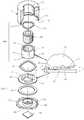
도4는 본 발명에 의한 렌즈 이송장치의 주요부품 사시도이다.Figure 4 is a perspective view of the main parts of the lens transfer apparatus according to the present invention.
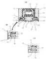
도5는 본 발명에 의한 렌즈 이송장치의 일 실시예의 중앙부 단면도이다.5 is a cross-sectional view of the central portion of an embodiment of a lens transport apparatus according to the present invention.
도6은 본 발명에 의한 렌즈 이송장치의 다른 실시예의 중앙부 단면도이다.6 is a cross sectional view of the center of another embodiment of the lens transfer apparatus according to the present invention.
* 도면의 주요부분에 대한 부호의 설명 *Explanation of symbols on the main parts of the drawings
10...하우징20...렌즈 배럴10.
30...배럴 홀더40...회전판30
50...압전구동기60...바닥판50
70...이미지 센서80...추가 렌즈군70 ...
300...구동부400...이송부300
본 발명은 렌즈 이송장치에 관한 것으로, 보다 상세하게는 압전구동기에서 발생하는 진행파에 구동력에 의한 회전운동을 렌즈의 직선운동으로 변화시켜 초점을 조절하거나 접사, 광학 줌 기능을 제공하는 카메라모듈의 렌즈 이송장치에 관한 것이다.The present invention relates to a lens transfer device, and more particularly, a lens of a camera module for adjusting focus or providing macro zoom and optical zoom by changing a rotational motion caused by a driving force in a traveling wave generated in a piezoelectric actuator into a linear motion of the lens. It relates to a conveying device.
일반적으로 카메라는 다수개의 렌즈를 구비하고 있으며 각각의 렌즈를 이동시켜 그 상대거리를 변화시킴으로써 광학적인 초점거리를 조절하도록 구성된다. 최근 카메라가 탑재된 휴대전화가 등장하여 휴대전화에 의해 정지화상 및 동영상의 촬영이 가능해지게 되었으며, 고해상도 및 고화질의 촬영을 위해 카메라의 성능이 점차 개선되어 가고 있는 추세이다.Generally, a camera has a plurality of lenses and is configured to adjust the optical focal length by moving each lens to change its relative distance. Recently, a mobile phone equipped with a camera has been introduced, and still pictures and videos can be taken by the mobile phone, and the performance of the camera is gradually being improved for high resolution and high quality shooting.
도1은 초점조절 기능이 없는 종래의 카메라 모듈의 사시도이다.1 is a perspective view of a conventional camera module without a focusing function.
도1과 같은 종래의 카메라 모듈은 이미지 센서(170) 및 필터는 하우징(110) 하부에 조립되고, 렌즈 배럴(120) 내에는 다수의 렌즈가 장착된다.In the conventional camera module as shown in FIG. 1, the
상기 렌즈 배럴(120)은, 상기 하우징(110)의 내주면과 상기 렌즈 배럴(120) 의 외주면에 형성된 나사산을 이용하여 렌즈 어레이(130)와 상기 이미지 센서(170)의 초점을 맞춘 후, 에폭시 등을 통하여 상기 하우징(110)에 고정된다.The
그러나, 이와 같은 고정 초점 방식은 특정 거리에서의 초점 조절이 불가능하여 화질의 선명도에 한계가 있다는 문제점이 발생한다.However, such a fixed focus method has a problem in that it is impossible to adjust the focus at a specific distance, thereby limiting the sharpness of the image quality.
따라서, 메가픽셀 이상의 카메라 모듈에서는 초점 기능이 필수적으로 요구된다.Therefore, focusing is indispensable for camera modules larger than megapixels.
이를 위해 자동초점 조절장치, 접사장치 및 광학 줌 장치 등을 구비한 카메라 모듈을 휴대전화에 적용할 필요성이 대두되었으나 종래 방식으로 제작된 카메라는 소형의 휴대전화에 탑재하는데 무리가 있었다.To this end, the necessity of applying a camera module having an automatic focusing device, a macro device, an optical zoom device, and the like to a mobile phone has emerged, but a conventionally manufactured camera has been difficult to mount in a small mobile phone.
즉, 종래의 방식은 이미지 센서와 렌즈간의 상대적인 거리를 변화시켜 초점조절 및/또는 광학 줌 기능의 구동원으로서 DC모터를 사용하고 있으나, 이러한 경우에는 다수개의 감속기어를 서로 연결하여 사용하는 것이므로 응답속도의 저하 및 회전속도의 편차로 인해 초점조절을 정밀하게 수행하기 위한 정확한 위치제어가 곤란할 뿐만 아니라, 부피가 크고 장치가 복잡하므로 휴대전화 내의 극도로 제한된 공간 속에서 초점조절 기능 등을 구현하기 어렵다는 문제점이 있다.That is, in the conventional method, the DC motor is used as a driving source of the focus adjustment and / or optical zoom function by changing the relative distance between the image sensor and the lens. In this case, since the plurality of reduction gears are connected to each other, the response speed It is difficult to precisely control the position for precise focusing due to the decrease in speed and the rotational speed, and it is difficult to implement the focusing function in the extremely limited space in the mobile phone because of its bulky and complicated device. There is this.
상기와 같은 문제점을 해결하기 위하여, 광학적 줌 기능 수행에 필요한 렌즈 이송을 자동 초점조절에 적용하는 방안을 고려해 볼 수 있을 것이다.In order to solve the above problems, it may be considered to apply the lens transfer required for performing the optical zoom function to the automatic focusing.
도2 및 도3은 각각 수동 및 자동으로 줌 기능을 수행하는 종래의 줌렌즈 결 합장치의 주요부품 구성도이다.2 and 3 are main components of a conventional zoom lens combining apparatus that performs a zoom function manually and automatically, respectively.
도2에서와 같이, 줌렌즈 결합장치는 내주면에 나사산이 형성된 원통형의 줌렌즈 케이스(250), 줌렌즈(210), 외주면에 나사산(241)이 형성된 카메라(240) 등으로 이루어지며, 사용자가 상기 줌렌즈 케이스(250)를 손으로 회전하면 상기 줌렌즈(210)와 상기 카메라(242)와 거리가 변하게 되어 줌인 혹은 줌아웃 된다.As shown in FIG. 2, the zoom lens coupling device includes a cylindrical
이러한 방식은 렌즈를 자동으로 이송하는 것이 아니므로 광학 줌 기능에는 이용될 수 있으나, 초점조절에는 이용되기 어렵다.This method can be used for the optical zoom function because it does not automatically transfer the lens, but is difficult to use for focusing.
즉, 렌즈의 직경이 작은 경우에는 그 초점거리가 짧아서 초점거리 조절시 렌즈의 이동거리도 짧아지므로, 따라서 도2와 같은 구성을 갖는 경우 사용자가 수동으로 줌렌즈 케이스(250)를 회전시켜 미세 초점거리를 조절하는 것은 매우 힘들다.That is, when the diameter of the lens is small, the focal length is short, so the movement distance of the lens is shortened when the focal length is adjusted. Therefore, when the lens has the configuration as shown in FIG. 2, the user manually rotates the
뿐만 아니라, 상기의 구성을 갖는 경우 줌 렌즈(210)가 회전하게 되어 광축이 변하므로 고해상도를 얻을 수 없다는 문제점이 있다.In addition, in the case of having the above configuration, since the
한편, 도3은 자동 줌기능을 구현하기 위해 모터(270)와, 상기 줌렌즈 결합장치는 상기 모터(270)의 동력을 이용하여 상기 줌렌즈 결합장치를 이송하는 이송장치(260)를 더 구비하며, 상기 카메라(240)의 외주부에 길이방향으로 형성된 슬라이딩홈(241)과, 내주부에 상기 슬라이딩홈(241)에 끼워지도록 돌기(255)가 형성된 줌렌즈 케이스(250)를 포함하여 구성된다.On the other hand, Figure 3 is a
사용자의 키 패드 조작 또는 센서 감지에 의해 상기 모터(270)가 구동됨에 따라, 상기 구동축(271)에 고정된 이송피니언(262)이 회전을 하게 되어, 상기 이송 랙(261)이 길이 방향으로 전후진을 하게 된다. 그 결과로서, 상기 줌렌즈 케이스(250)가 전후방으로 이동을 하여, 상기 줌렌즈(210)가 상기 카메라(240)에 대한 거리가 달라짐에 따라, 광학 줌 기능을 하게 된다.As the
그러나, 이와 같은 구성을 갖는 경우에도 줌렌즈 케이스(250) 외부에 이송을 위한 장치를 필요로 하므로, 카메라 모듈의 부피가 커진다는 문제를 근본적으로 해결할 수 없으며, 극도로 제한된 공간 내에서 구동되어야 하는 소형 광학기기에는 적합하지 않다.However, even in such a configuration, since a device for transporting outside the
따라서, 휴대폰용 카메라 등의 소형 광학기기에서 초점조절, 접사, 광학 줌 등의 기능을 수행하기 위해, 소형화가 가능하면서도 미세한 렌즈 이송을 통해 고해상도를 얻을 수 있는 렌즈 이송장치가 요구된다.Therefore, in order to perform functions such as focus adjustment, macro, optical zoom, and the like in a small optical device such as a camera for a mobile phone, a lens transport apparatus capable of miniaturization and high resolution through fine lens transport is required.
본 발명은 상기와 같은 문제점을 해결하기 위한 것으로, 크기가 작고 구성이 간단하면서도 정밀한 카메라 모듈의 렌즈 이송장치를 제공하는 것을 목적으로 한다.The present invention is to solve the above problems, an object of the present invention is to provide a lens transfer device of a small size, simple configuration, yet precise camera module.
또한, 본 발명은 정밀한 렌즈 이송을 통해 미세한 초점조절을 함으로써 고해상도, 고선명도의 화상을 얻을 수 있는 카메라 모듈의 렌즈 이송장치를 제공함을 목적으로 한다.
In addition, an object of the present invention is to provide a lens transfer device of a camera module that can obtain a high-resolution, high-definition image by making fine focus adjustment through precise lens transfer.
상기와 같은 목적을 달성하기 위하여 본 발명은,The present invention to achieve the above object,
인가된 전압에 의해 기계적 구동력을 발생시키는 링 형상의 압전구동기(piezoelectric actuator) 및 상기 압전구동기의 상부에 위치하고 상기 압전구동기의 구동력에 의해 렌즈의 광축을 중심으로 회전하는 회전판을 구비하는 구동부;A driving unit including a ring-shaped piezoelectric actuator for generating a mechanical driving force by an applied voltage and a rotating plate positioned above the piezoelectric driver and rotating about an optical axis of the lens by a driving force of the piezoelectric driver;
상기 회전판의 상면과 접촉하고 내부에 상기 렌즈가 고정되는 중공형 배럴 홀더를 구비하며, 상기 회전판이 회전할 때 상기 렌즈의 광축방향으로 직선이송되는 이송부; 및 A conveying part having a hollow barrel holder in contact with an upper surface of the rotating plate and having the lens fixed therein, and linearly moving in the optical axis direction of the lens when the rotating plate rotates; And
상기 구동부와 이송부를 내부에 수용하고, 상기 이송부가 상기 렌즈의 광축방향으로 직선이송되도록 안내하는 가이드 수단이 형성된 중공형 하우징;A hollow housing having the driving unit and the conveying unit therein and having guide means for guiding the conveying unit to be linearly moved in the optical axis direction of the lens;
을 포함하며,Including;
상기 압전구동기의 구동력에 의해 상기 회전판이 회전하면 상기 배럴 홀더의 하부와 상기 회전판 상면의 접촉에 의해 상기 이송부가 상기 하우징의 가이드 수단을 통해 안내되어 상기 렌즈의 광축방향으로 이송되는 카메라모듈의 렌즈 이송장치를 제공한다.When the rotating plate is rotated by the driving force of the piezoelectric actuator, the conveying unit is guided through the guide means of the housing by the contact of the lower part of the barrel holder and the upper surface of the rotating plate, thereby transferring the lens of the camera module to be transferred in the optical axis direction of the lens. Provide the device.
바람직하게는, 상기 구동부는 상면에 상기 압전구동기가 안착되는 안착홈이 함몰형성되고 이미지 센서를 구비하는 바닥판을 더 포함하며, 상기 압전구동기는 진행파 구동형식의 압전구동기이다.Preferably, the driving unit further includes a bottom plate having a recessed groove in which the piezoelectric driver is seated and having an image sensor, and the piezoelectric driver is a piezoelectric driver of a traveling wave driving type.
또한 바람직하게는, 상기 회전판은 상면에 점진적으로 높이가 증가하는 적어도 하나 이상의 경사 캠이 돌출형성되어 있고, 상기 배럴 홀더는 하부면에 상기 경 사 캠과 접촉하는 캠 팔로우어가 상기 경사 캠에 대응하여 돌출형성되어 있으며, 상기 이송부는 상기 회전판이 광축을 중심으로 회전할 때 상기 경사 캠과 캠 팔로우어의 접촉에 의해 이송된다.Also preferably, the rotating plate may have at least one inclined cam projecting from the upper surface of the rotating plate gradually increasing in height, and the barrel holder may have a cam follower in contact with the inclined cam at a lower surface thereof. It is protruding and the conveying part is conveyed by the contact between the inclined cam and the cam follower when the rotating plate rotates about the optical axis.
더욱 바람직하게는, 상기 경사 캠은 상기 렌즈의 광축을 중심으로 하여 원주방향으로 일정한 각도마다 등간격을 두고 상기 회전판의 상면에 돌출형성되며, 상기 캠 팔로우어는 상기 경사 캠에 대응하여 상기 배럴 홀더의 하면에 돌출형성된다.More preferably, the inclined cam is formed to protrude on the upper surface of the rotating plate at regular intervals in the circumferential direction with respect to the optical axis of the lens, the cam follower is formed of the barrel holder corresponding to the inclined cam Protruding on the lower surface.
바람직하게는, 상기 배럴 홀더는 외주면에 적어도 하나 이상의 활주부가 돌출형성되고, 상기 하우징은 상기 활주부와 대응하는 내주면에 상기 활주부를 수용하여 활주시키는 안내부가 함몰형성되며, 상기 활주부 및 상기 안내부는 상기 렌즈의 광축에 평행하게 형성된다.Preferably, the barrel holder has at least one sliding portion protruding from the outer circumferential surface, the housing is formed with a guide portion for receiving and sliding the sliding portion on the inner peripheral surface corresponding to the sliding portion, the sliding portion and the guide portion It is formed parallel to the optical axis of the lens.
또한 바람직하게는, 상기 바닥판은 상기 렌즈의 광축을 중심축으로 하는 중공 원통형 회전지지부가 상면에 돌출형성되고, 상기 회전지지부는 상기 회전판의 중앙에 관통형성된 내주면에 삽입되어 상기 회전판의 회전시 상기 회전판의 반경 방향으로의 운동을 제한한다.Also preferably, the bottom plate may have a hollow cylindrical rotation support portion protruding from an upper surface of the lens, and the rotation support portion may be inserted into an inner circumferential surface penetrating through the center of the rotation plate to rotate the rotation plate. Limit the radial movement of the turntable.
바람직하게는, 상기 이송부는 상기 경사 캠과 상기 캠 팔로우어를 탄성적으로 가압하여 접촉하도록 하는 제1 탄성수단을 더 포함할 수 있으며, 상기 구동부는 상기 압전구동기 상면과 상기 회전판 하면을 예압된 탄성력으로 가압하는 제2 탄성수단을 더 포함할 수 있으며, 상기 제1 및 제2 탄성수단은 링 형상의 예압된 파도스프링(wave spring)이다.Preferably, the transfer unit may further include a first elastic means for elastically pressing the inclined cam and the cam follower to come into contact with each other, and the driving unit has a preloaded elastic force on the upper surface of the piezoelectric actuator and the lower surface of the rotary plate. It may further comprise a second elastic means for pressing, wherein the first and second elastic means is a ring-shaped pre-loaded wave spring (wave spring).
또한, 상기 렌즈 이송장치는 피사체의 거리를 측정하는 센서의 신호 또는 사용자의 지시에 의해 상기 압전구동기의 구동을 제어하는 제어부를 더 포함할 수 있으며, 광학 줌 또는 접사 기능 수행을 위해 적어도 하나 이상의 렌즈를 구비하는 추가 렌즈군을 더 포함할 수도 있다.In addition, the lens transport apparatus may further include a control unit for controlling the driving of the piezoelectric actuator by a signal of a sensor measuring a distance of a subject or a user's instruction, and at least one lens for performing an optical zoom or macro function. It may further include an additional lens group having a.
이하 본 발명의 실시예에 대하여 첨부된 도면에 따라서 보다 상세히 설명한다.Hereinafter, embodiments of the present invention will be described in detail with reference to the accompanying drawings.
도4는 본 발명에 의한 렌즈 이송장치의 부품 사시도이며, 도5는 본 발명에 의한 렌즈 이송장치의 중앙부 단면도이다.4 is a perspective view of a part of the lens transfer apparatus according to the present invention, and FIG. 5 is a cross-sectional view of a central portion of the lens transfer apparatus according to the present invention.
먼저 도4에서 도시한 바와 같이, 본 발명에 의한 카메라모듈의 렌즈 이송장치는 구동부(300), 이송부(400) 및 상기 구동부와 상기 이송부를 수용하는 하우징(10)을 포함한다.First, as shown in FIG. 4, the lens transfer apparatus of the camera module according to the present invention includes a
상기 구동부(300)는 인가된 전압에 의해 기계적 구동력을 발생시키는 링 형상의 압전구동기(piezoelectric actuator)(50) 및 상기 압전구동기(50)의 상부에 위치하고 상기 압전구동기의 구동력에 의해 렌즈의 광축을 중심으로 회전하는 회전판(40)을 구비한다.The driving
여기서, 렌즈는 후술하는 바와 같이 배럴 홀더(30)에 고정된다.Here, the lens is fixed to the
바람직하게는, 상기 회전판은 상면에 점진적으로 높이가 증가하는 적어도 하나 이상의 경사 캠이 돌출형성되어 있다.Preferably, the rotary plate is formed with at least one inclined cam protruding gradually increasing in height on the upper surface.
또한 바람직하게는, 상기 구동부(300)는 상면에 상기 압전구동기(50)가 안착 되는 안착홈이 함몰형성되고 이미지 센서를 구비하는 바닥판을 더 포함할 수 있다.Also preferably, the driving
상기 압전구동기(50)는 상기 회전판(40)에 구동력을 전달하여 회전판을 회전시키는 역할을 하며, 빛이 렌즈를 투과하여 이미지센서(70)에 도달할 수 있도록 링 형상을 가진다.The
또한, 상기 압전구동기(50)는 정역전이 가능하고 소형화가 용이하며 수명이 길다는 점에서 정재파 형식보다는 진행파 구동형식의 압전구동기인 것이 바람직하며, 수백 나노미터(㎚) 내지 수십 마이크로미터(㎛)의 변위와 수 킬로헤르쯔(kHz)이상의 작동주파수를 가진다.In addition, the
한편, 상기 이송부(400)는 상기 회전판(30)의 상면과 접촉하고 내부에 상기 렌즈가 고정되는 중공형의 배럴 홀더(30)를 구비하며, 상기 회전판(30)이 회전하면 상기 배럴 홀더(30)의 하부와 상기 회전판(30) 상면의 접촉에 의해 상기 렌즈의 광축방향으로 직선이송된다.On the other hand, the
바람직하게는, 상기 배럴 홀더(30)는 하면에 상기 회전판(40)의 경사 캠(41)과 접촉하는 캠 팔로우어(32)가 상기 경사 캠(41)에 대응하여 돌출형성되어 있으며, 이때 상기 이송부는 상기 회전판(40)의 회전시 상기 경사 캠(41)과 캠 팔로우어(32)의 접촉에 의해 이송된다.Preferably, the
또한, 상기 배럴 홀더(30)의 내부에는 적어도 하나 이상의 렌즈를 갖는 렌즈 배럴(20)이 고정되는 것이 바람직하다.In addition, it is preferable that the
여기서, 적어도 하나 이상의 렌즈는 렌즈의 광축이 일치하도록 렌즈 배럴 (20)에 조립되며, 상기 렌즈 배럴(20)의 외주면에는 상기 배럴 홀더(30)의 내주면의 나사산과 맞물리도록 나사산이 형성되어 있다.Here, the at least one lens is assembled to the
또한, 상기 렌즈 배럴(20)은 배럴 홀더(30)의 내주면에 조립되어 초기 위치가 보정된 후 에폭시 등으로 고정된다.In addition, the
한편, 상기 하우징(10)은 중공형으로서 상기 구동부(300)와 이송부(400)를 내부에 수용하고, 상기 이송부(400)가 상기 렌즈의 광축방향으로 직선이송되도록 안내하는 가이드 수단이 형성되어 있다.On the other hand, the
본 발명의 실시예에 관하여 보다 상세히 설명하면 다음과 같다.Hereinafter, the embodiment of the present invention will be described in detail.
도4에 도시된 바와 같이, 상기 회전판(40)의 경사 캠(41)은 상기 렌즈의 광축을 중심으로 하여 원주방향으로 일정한 각도마다 등간격을 두고 상기 회전판(40)의 상면에 돌출 형성되며, 상기 배럴 홀더(30)의 캠 팔로우어(32)는 상기 경사 캠(41)에 대응하여 상기 배럴 홀더(30)의 하면에 돌출형성된다.As shown in Figure 4, the
바람직하게는, 상기 경사 캠(41)은 안정된 3점 지지를 위하여 상기 회전판(40)의 상면에 원주방향으로 120°마다 형성되며, 이에 대응하는 상기 캠 팔로우어(32) 역시 120°마다 상기 배럴 홀더(30)의 하면에 돌출 형성된다.Preferably, the
더욱 바람직하게는, 도4의 확대부에 도시된 것과 같이, 상기 경사 캠(41)은 상기 배럴 홀더(30)의 하면과 상기 경사 캠(41)이 서로 간섭되는 것을 막기 위하여 경사 캠(41)의 최대 높이(H)가 캠 팔로우어(32)의 최대 높이(h)보다 낮아야 한다.More preferably, as shown in the enlarged portion of FIG. 4, the
또한, 상기 캠 팔로우어(32)는 상기 경사 캠(41)의 경사면과 점접촉을 하도록 반구형 형상인 것이 바람직하나, 선접촉을 하도록 호형 단면으로 이루어질 수도 있다.In addition, the
도4의 확대부에 도시된 것과 같이, 상기 캠 팔로우어(32)는 상기 경사 캠(41)의 높이가 0인 위치에서 이웃하는 경사 캠의 단부에 접촉하여 경사 캠이 형성되지 않은 회전판의 상면과 상기 캠 팔로우어(32)의 접촉이 제한되므로, 상기 캠 팔로우어(32)는 상기 경사 캠(41)의 경사면을 따라서만 접촉하게 된다.As shown in the enlarged portion of FIG. 4, the
즉, 렌즈 배럴(20)이 상방으로 이동하는 경우에는 상기 캠 팔로우어(32)는 상기 경사 캠(41)의 높이가 0인 위치로부터 상기 경사 캠(41)의 높이가 H인 방향으로 상기 경사 캠(41)의 경사면을 따라 이동하며, 도4 확대부의 이점쇄선으로 표시된 캠 팔로우어는 상기 경사 캠(41)의 경사면에 접촉하고 있는 캠 팔로우어(32)를 도시하고 있다.That is, when the
한편, 효과적으로 렌즈의 이송을 구현하기 위해서는 상기 배럴 홀더(30) 및 이에 고정된 렌즈 배럴(20)은 상기 회전판(40)의 회전각도에 정비례하여 렌즈의 광축방향으로 이송되는 것이 바람직하며, 상기 배럴 홀더(30)의 이송거리는 상기 경사 캠의 최대 높이(H)보다 작다.Meanwhile, in order to effectively transfer the lens, the
즉, 상기 경사 캠(41)의 형상은 캠 팔로우어(32)와 경사 캠(41)이 접촉하는 높이가 회전판의 회전각도에 따라 선형적으로 증감하도록 이루어져야 하며, 이러한 형상을 갖는 경사 캠(41)을 사용함으로써 렌즈의 이송에 필요한 회전판(40)의 회전각도가 선형적으로 결정될 수 있다.That is, the shape of the
한편, 카메라폰, 디지털 카메라 등과 같이 소형 광학기기의 카메라모듈에 사용되는 렌즈는 소형이므로, 렌즈가 직선이송되지 않고 회전되어 이송된다면 렌즈의 수차 특성, 렌즈의 회전축과 광축의 불일치 등으로 인하여 이미지 센서(70)와 렌즈간의 광축이 변할 수 있게 되어 고해상도를 얻을 수 없다.On the other hand, the lens used in the camera module of small optical devices such as camera phones, digital cameras, etc. is small, so if the lens is rotated and transported without linear movement, the image sensor may be damaged due to the aberration characteristics of the lens and the inconsistency between the rotation axis and optical axis of the lens The optical axis between the
이러한 문제점을 해결하기 위하여 렌즈는 광축 방향으로 이송되는 것이 바람직하게 된다.In order to solve this problem, the lens is preferably transferred in the optical axis direction.
이러한 광축방향의 직선 이송을 구현하기 위하여, 상기 배럴 홀더(30)는 외주면에 적어도 하나 이상의 활주부(31)가 돌출형성되고, 상기 하우징(10)은 상기 활주부(31)와 대응하는 내주면에 상기 활주부(31)를 수용하여 활주시키는 안내부(11)가 함몰형성되며, 상기 활주부(31) 및 안내부(11)는 상기 렌즈의 광축에 평행하게 형성되는 것이 바람직하다.In order to realize the linear transport in the optical axis direction, the
이와는 반대로, 상기 하우징(10)의 내주면에 활주부(11)를 돌출형성하고, 상기 배럴 홀더(30)의 외주면에 안내부(31)를 함몰형성하는 구성도 가능할 것이다.On the contrary, the sliding
또한, 상기 캠 팔로우어(32)와 경사 캠(41)의 경사면이 접촉하는 위치가 경사면의 내외측으로 변한다면 회전판의 회전각도에 정비례하여 렌즈가 이송되는 것을 보장하기 어려우므로, 정밀한 이송을 위하여 상기 배럴 홀더(30)의 하부에 돌출형성된 캠 팔로우어(32)는 광축을 중심으로 일정한 반경을 유지하며 상기 경사 캠(41)과 접촉하는 것이 바람직하며, 이를 위해서는 상기 회전판(40)의 회전축과 광축이 일치하도록 유지하는 것이 필요하다. In addition, if the position where the inclined surface of the
따라서, 바닥판(60)의 상면에는 상기 렌즈의 광축을 중심축으로 하는 중공 원통형 회전지지부(61)가 돌출형성되고, 상기 회전지지부(61)는 상기 회전판(40)의 중앙에 관통형성된 내주면(42)에 삽입되어 상기 회전판(40)의 회전시 상기 회전판의 반경 방향으로의 운동을 제한하도록 하는 것이 바람직하다.Therefore, a hollow cylindrical
한편, 상기 하우징(10)은 상기 바닥판(60)에 의해 하부가 폐쇄되며, 상기 바닥판(60)은 상기 하우징(10)의 하부에 고정되어 상기 하우징과 상기 바닥판의 상대 회전을 제한하므로 상기 하우징은 압전구동기(50)의 구동에 의한 영향을 받지 않는다.On the other hand, the
바람직하게는, 상기 하우징(10)은 외주면 하단에 복수개의 상부 결합턱(14)이 요철 형상으로 형성되고, 상기 바닥판(60)은 외주면에 상기 상부 결합턱(14)에 대응하여 맞물리는 하부 결합턱(63)이 형성되며, 상기 상부 결합턱(14)과 하부 결합턱(63)의 맞물림으로 인해 상기 하우징(10)과 바닥판(60)이 고정되도록 할 수 있다.Preferably, the
더욱 바람직하게는, 도5b에서와 같이 상기 상부 결합턱(14)은 중심부로 돌출형성된 돌출부를 포함하며, 상기 돌출부에 의해 상기 상부 결합턱(14)과 하부 결합턱(63)의 맞물림이 유지되도록 할 수 있다.More preferably, as shown in FIG. 5B, the
이때, 상기 바닥판(60)은 상기 하우징(10)의 하부측에서 상방으로 조립되며, 조립을 할 때에는 상기 상부 결합턱(14)의 돌출부가 바깥쪽으로 벌어지면서 상기 상부 결합턱(14)과 하부 결합턱(63)이 맞물리며, 맞물린 후에는 탄성에 의해 상부 결합턱(14)의 돌출부가 상기 바닥판(60)을 지지하게 된다.At this time, the
즉, 바닥판(60)의 외주면이 함몰되고 하우징(10)의 외주면 하단이 돌출된 부분은 도5b에서와 같은 단면을 가지게 되고, 바닥판(60)의 외주면이 돌출되고 하우징(10)의 외주면 하단이 함몰된 부분은 도5c에서와 같은 단면을 가지게 된다.That is, the portion where the outer circumferential surface of the
이와 같은 형상을 갖는 상부 결합턱(14)과 하부 결합턱(63)을 통하여 용접, 나사체결 등 별도의 공정없이도 하우징(10)과 바닥판(60)을 고정할 수 있으므로 조립성이 개선되는 효과가 있게 된다.Through the upper coupling jaw (14) and the lower coupling jaw (63) having such a shape can be fixed to the
한편, 도4 및 도5에 도시된 바와 같이 상기 이송부(400)는 상기 경사 캠(41)과 상기 캠 팔로우어(32)를 탄성적으로 가압하여 접촉하도록 하는 제1 탄성수단(15)을 포함할 수 있으며, 상기 제1 탄성수단(15)은 조립의 편의성 및 전면에 걸쳐 일정한 탄성력을 제공하기 위하여 링 형상의 예압된 파도스프링(wave spring)인 것이 바람직하다.Meanwhile, as shown in FIGS. 4 and 5, the
또한, 상기 경사 캠(41)과 캠 팔로우어(32)를 탄성적으로 가압하고, 상기 배럴 홀더(30)가 이미지 센서(70)의 반대측으로 이송되면 압축되어 이송 공간을 제공하도록 하기 위해, 상기 제1 탄성수단(15)은 도5a에서와 같이 상기 하우징(10) 내면에 형성된 상부단(12)과 상기 배럴 홀더(30)의 상면 사이에 구비되는 것이 바람직하다.In addition, in order to elastically pressurize the
또한, 상기 구동부(300)는 상기 압전구동기(50) 상면과 상기 회전판(40) 하면을 예압된 탄성력으로 가압하는 제2 탄성수단(16)을 더 포함할 수 있으며, 상기 제2 탄성수단(16)은 조립의 편의성 및 전면에 걸쳐 일정한 탄성력을 제공하기 위하 여 링 형상의 예압된 파도스프링(wave spring)인 것이 바람직하다.In addition, the driving
또한, 도5a에서와 같이 상기 제2 탄성수단(16)은 상기 회전판(40) 상면과 하우징 내면의 중간단(13) 사이에 구비되어 상기 압전구동기(50) 상면과 상기 회전판(40) 하면을 예압된 탄성력으로 가압하는 것이 바람직하다.In addition, the second elastic means 16 is provided between the upper surface of the
한편, 본 발명에 의한 카메라모듈의 렌즈 이송장치는 자동 초점조절 기능을 수행하기 위하여 피사체의 거리를 측정하는 센서의 신호 또는 사용자의 지시에 의해 상기 압전구동기(50)의 구동을 제어하는 제어부(미도시)를 더 포함하는 것이 바람직하다.On the other hand, the lens transfer apparatus of the camera module according to the present invention is a control unit for controlling the driving of the piezoelectric actuator (50) by the signal of the sensor for measuring the distance of the subject or the user's instructions in order to perform the automatic focusing function (not shown) It is preferred to further include c).
도6은 본 발명에 의한 렌즈 이송장치의 다른 실시예를 보여주는 중앙부 단면도로서, 추가 렌즈군(80)을 포함하고 있다.Fig. 6 is a cross sectional view of the central portion showing another embodiment of the lens transfer apparatus according to the present invention, and includes an
도6에 도시된 바와 같이, 본 발명에 의한 카메라모듈의 렌즈 이송장치는 광학 줌 또는 접사 기능 수행을 위해 적어도 하나 이상의 렌즈를 구비하는 추가 렌즈군(80)을 더 포함할 수 있으며, 광축의 전후로 이송되는 렌즈 배럴(20)의 렌즈와 상기 추가 렌즈군(80)에 구비된 렌즈의 상호 작용에 의해 광학 줌 기능 또는 접사 기능의 수행이 가능하게 된다.As shown in FIG. 6, the lens transport apparatus of the camera module according to the present invention may further include an
이때, 상기 추가 렌즈군(80)은 상기 렌즈 배럴(20)에 구비된 렌즈가 이송되는 구조 등을 이용하여 이송가능하도록 장착할 수도 있고, 이미지 센서(70)에 대해 고정된 위치에 장착할 수도 있다.In this case, the
상기 추가 렌즈군(80)이 이송되도록 하는 경우, 본 발명에 의한 렌즈 이송장치는 상기 렌즈 배럴(20)의 이송량에 따라 상기 추가 렌즈군(80)이 종속적으로 이송되게 하는 구조로 형성될 수도 있고, 별도의 구동부(300) 및 이송부(400)를 추가적으로 구비하여 상기 추가 렌즈군(80)이 상기 렌즈 배럴(20)의 이송과는 독립적으로 이송되게 할 수도 있다.When the
또한 상기 이미지 센서(70)에 대해 고정된 위치에 장착하는 경우, 상기 추가 렌즈군(80)은 도6에서와 같이 상기 바닥판(10)의 중앙에 관통형성된 회전지지부(61)에 고정될 수 있으나, 이미지 센서(70)와의 일정간격이 유지되는 위치라면 하우징(10) 상부에 배치되는 것도 가능할 것이다.In addition, when mounted in a fixed position with respect to the
이때, 상기 렌즈 배럴(20)의 렌즈와 상기 추가 렌즈군(80)의 렌즈 특성은 추가 렌즈군(80)의 장착 위치, 고정/이송 여부 등에 따라 적절하게 선택될 수 있다.In this case, the lens of the
또한, 상기 추가 렌즈군(80)의 광축은 상기 배럴 홀더(30) 및 이에 고정된 렌즈 배럴(20)에 구비된 렌즈의 광축과 일치하도록 고정되어야 한다.In addition, the optical axis of the
바람직하게는, 사용자의 접사, 줌인 또는 줌아웃의 구동 지시를 받아 상기 압전구동기(50)의 구동을 제어하여 상기 배럴 홀더(30) 및 이에 고정된 렌즈 배럴(20)을 이송시키는 제어부(미도시)를 더 포함할 수 있다.Preferably, a control unit (not shown) which transfers the
상기와 같은 구성을 갖는 본 발명의 일실시예의 작용에 대해 도4 및 도5를 참조하여 살펴본다.The operation of an embodiment of the present invention having the above configuration will be described with reference to FIGS. 4 and 5.
먼저, 압전구동기(50)에 전압을 인가한다. 이때, 상기 압전구동기(50)는 피 사체의 위치를 감지하는 센서 또는 사용자의 지시에 의해 압전구동기의 구동을 제어하는 제어부(미도시)의 신호에 의해 구동될 수도 있다.First, a voltage is applied to the
상기 압전구동기(50)에 구동신호가 인가되면 압전구동기는 진행파(정현파) 에 의한 기계적 구동력을 발생하고 압전구동기의 구동력에 의해 회전판(40)이 회전하게 된다. 이때, 상기 압전구동기(50)와 상기 회전판(40) 사이의 접촉력 유지를 위하여 제2 탄성수단(16)을 추가적으로 구성할 수 있다.When a driving signal is applied to the
또한, 상기 회전판(40)의 회전에 따라 경사 캠(41)이 회전하게 되어 배럴 홀더(30) 하부의 캠 팔로우어(32)와 접촉하는 경사 캠 부분의 높이가 증가하게 된다.In addition, as the rotating
이때, 상기 경사 캠(41)과 접촉하는 상기 캠 팔로우어(32)가 이미지 센서(70)의 반대방향으로 밀리게 되고, 상기 배럴 홀더(30)의 외면에 광축방향으로 돌출형성된 활주부(31)가 하우징의 내면에 광축방향으로 함몰형성된 안내부(11)에 안내되어 상기 배럴 홀더(30) 및 이에 고정된 렌즈 배럴(20)이 이미지 센서 반대측 광축방향으로 이송된다. 여기서, 제1 탄성수단(15)에 의해 상기 경사 캠(41)과 캠 팔로우어(32)의 접촉력이 유지되도록 할 수 있다.At this time, the
한편, 압전구동기에 더 이상 전압이 인가되지 않으면 압전구동기는 구동을 멈추게 되고, 렌즈의 이송은 끝나게 된다.On the other hand, when the voltage is no longer applied to the piezoelectric actuator, the piezoelectric actuator stops driving, and the transfer of the lens is finished.
이때, 피사체의 거리를 측정하는 센서에 의해 결정된 렌즈 이송위치에 다다르거나 사용자가 구동멈춤 지시를 하면 제어부가 상기 압전구동기(50)에 구동멈춤 신호를 인가하고, 이에 의해 렌즈의 이송이 끝날 수도 있다.At this time, when the user reaches the lens transfer position determined by the sensor for measuring the distance of the subject or when the user instructs to stop driving, the control unit applies a driving stop signal to the
전술한 바와 반대로, 이미지 센서 측으로 렌즈를 이송하는 경우에도 상기와 같은 원리로 작동된다.Contrary to the above, even when the lens is transferred to the image sensor side, the same principle as described above.
일반적으로, 진행파 구동형식의 압전구동기(50)는 수백 나노미터(㎚) 내지 수십 마이크로미터(㎛)의 변위와 수 킬로헤르쯔(kHz)이상의 작동주파수를 가지므로 미세한 변위 조절이 가능하고, 따라서 정밀한 렌즈 이송을 구현하여 고해상도, 고선명도의 화상을 얻을 수 있으며, 소형 광학기기의 카메라모듈에 적용할 수 있을 만큼 소형화가 가능하다는 유리한 효과가 있게 된다.In general, the traveling wave drive
한편, 광학 줌 기능 또는 접사 기능의 수행 역시 상기와 같은 작용에 의해 이루어진다.On the other hand, performance of the optical zoom function or macro function is also performed by the above operation.
다만, 고배율의 광학 줌 기능 수행을 위해서는 렌즈의 이송거리가 다소 길어질 필요가 있으므로, 이러한 경우에는 광학 줌 기능 수행에 필요한 렌즈 이송거리만큼 상기 경사 캠(41)의 높이를 높이면 되고, 빠른 이송동작 수행을 위해 상기 압전구동기(50)의 변위 및/또는 작동주파수를 크게 설정하면 될 것이다.However, in order to perform a high magnification optical zoom function, the lens feeding distance needs to be slightly longer. In this case, the height of the
이상과 같이 본 발명에 의하면, 압전구동기의 구동에 의한 회전이송을 직선 이송으로 변화시켜 렌즈를 이송함으로써, 크기가 작고 구성이 간단하면서도 정밀한 렌즈 이송장치의 구현이 가능하다는 효과가 있게 된다.As described above, according to the present invention, by changing the rotational movement by the drive of the piezoelectric actuator to a linear conveyance to convey the lens, it is possible to implement a small lens size, simple configuration and precise lens conveying apparatus.
또한, 본 발명은 압전구동기를 이용하여 미세한 초점조절이 가능하므로, 고해상도, 고선명도의 화상을 얻을 수 있다는 효과가 있다.In addition, since the present invention enables fine focus adjustment using a piezoelectric actuator, there is an effect that an image of high resolution and high definition can be obtained.
한편, 상기와 같은 소형의 렌즈 이송장치를 구현함으로써, 카메라 폰, 디지털 카메라 등에 사용되는 카메라모듈의 초점조절, 광학 줌밍(zooming), 접사 등에 이용될 수 있다는 효과가 있게 된다.
On the other hand, by implementing the compact lens transfer device as described above, there is an effect that it can be used for focusing, optical zooming, macro, etc. of the camera module used in the camera phone, digital camera, and the like.
본 발명은 특정한 실시예에 관하여 도시하고 설명하였지만, 당업계에서 통상의 지식을 가진 자라면 이하의 특허청구범위에 기재된 본 발명의 사상 및 영역을 벗어나지 않는 범위 내에서 본 발명을 다양하게 수정 및 변경시킬 수 있음을 밝혀두고자 한다.While the invention has been shown and described with respect to particular embodiments, it will be apparent to those skilled in the art that various modifications and variations can be made in the present invention without departing from the spirit and scope of the invention as set forth in the claims below. I want to make it clear.
Claims (23)
Translated fromKoreanPriority Applications (5)
| Application Number | Priority Date | Filing Date | Title |
|---|---|---|---|
| KR1020040069985AKR100550907B1 (en) | 2004-09-02 | 2004-09-02 | Lens transfer device of camera module |
| US11/007,306US20060044455A1 (en) | 2004-09-02 | 2004-12-09 | Lens-positioning device of camera module |
| DE102004060785ADE102004060785B4 (en) | 2004-09-02 | 2004-12-17 | Lens positioning device for a camera module |
| JP2004372374AJP2006072294A (en) | 2004-09-02 | 2004-12-22 | Lens transfer device of camera module |
| CNB2004101045788ACN100350289C (en) | 2004-09-02 | 2004-12-22 | Lens-positioning device of camera module |
Applications Claiming Priority (1)
| Application Number | Priority Date | Filing Date | Title |
|---|---|---|---|
| KR1020040069985AKR100550907B1 (en) | 2004-09-02 | 2004-09-02 | Lens transfer device of camera module |
Publications (1)
| Publication Number | Publication Date |
|---|---|
| KR100550907B1true KR100550907B1 (en) | 2006-02-13 |
Family
ID=36139334
Family Applications (1)
| Application Number | Title | Priority Date | Filing Date |
|---|---|---|---|
| KR1020040069985AExpired - Fee RelatedKR100550907B1 (en) | 2004-09-02 | 2004-09-02 | Lens transfer device of camera module |
Country Status (5)
| Country | Link |
|---|---|
| US (1) | US20060044455A1 (en) |
| JP (1) | JP2006072294A (en) |
| KR (1) | KR100550907B1 (en) |
| CN (1) | CN100350289C (en) |
| DE (1) | DE102004060785B4 (en) |
Cited By (5)
| Publication number | Priority date | Publication date | Assignee | Title |
|---|---|---|---|---|
| WO2013073743A1 (en)* | 2011-11-15 | 2013-05-23 | (주)이즈미디어 | Lens focus adjusting method and adjusting apparatus |
| KR101453006B1 (en)* | 2011-12-01 | 2014-10-21 | 삼성전기주식회사 | Camera module |
| US9596394B2 (en) | 2015-01-16 | 2017-03-14 | Samsung Electronics Co., Ltd. | Camera and lens module |
| KR101903381B1 (en)* | 2013-12-03 | 2018-10-02 | 볼리미디어 홀딩즈 컴퍼니 리미티드 | Zoom/focus device and zoom lens |
| US12273624B2 (en) | 2021-12-08 | 2025-04-08 | Samsung Electronics Co., Ltd. | Camera module and electronic device including the same |
Families Citing this family (49)
| Publication number | Priority date | Publication date | Assignee | Title |
|---|---|---|---|---|
| JP4923535B2 (en)* | 2005-01-27 | 2012-04-25 | コニカミノルタオプト株式会社 | Lens unit and imaging unit |
| US20060274186A1 (en)* | 2005-06-02 | 2006-12-07 | Akihiro Machida | Lens focusing device with latching shoe |
| JP4123250B2 (en)* | 2005-06-24 | 2008-07-23 | 松下電器産業株式会社 | Image sensor driving apparatus and imaging apparatus using the same |
| WO2007029559A1 (en)* | 2005-09-09 | 2007-03-15 | Murata Manufacturing Co., Ltd. | Ultrasonic sensor |
| CN100394238C (en)* | 2006-04-14 | 2008-06-11 | 博立码杰通讯(深圳)有限公司 | Integrated focusing/zooming system of optical apparatus |
| KR100770866B1 (en)* | 2006-06-01 | 2007-10-26 | 삼성전자주식회사 | Camera lens module with auto focus |
| JP2008152032A (en)* | 2006-12-18 | 2008-07-03 | Smk Corp | The camera module |
| KR100844493B1 (en)* | 2007-01-10 | 2008-07-08 | 삼성전자주식회사 | Mobile terminal operation method and device |
| CN100578278C (en)* | 2007-02-13 | 2010-01-06 | 财团法人工业技术研究院 | Optical focusing device |
| WO2008124457A1 (en)* | 2007-04-03 | 2008-10-16 | Shuxiang Dong | Miniature piezoelectric motor and method of driving elements using same |
| US7656460B2 (en)* | 2007-08-21 | 2010-02-02 | Sony Ericsson Mobile Communications Ab | Autofocus assembly that adjusts a lens in the optical axis direction by alignment of holes in a spacing ring that receive ball bearings |
| KR100927420B1 (en)* | 2008-04-24 | 2009-11-19 | 삼성전기주식회사 | Lens drive module |
| CN101542348B (en)* | 2008-10-14 | 2011-04-20 | 香港应用科技研究院有限公司 | Multi-actuator lens actuating device |
| JP5407409B2 (en)* | 2009-02-23 | 2014-02-05 | コニカミノルタ株式会社 | Imaging device and manufacturing method thereof |
| US12328491B1 (en) | 2009-03-25 | 2025-06-10 | Magna Electronics Inc. | Vehicular camera and lens assembly |
| ES2693455T3 (en) | 2009-03-25 | 2018-12-11 | Magna Electronics Inc. | Camera assembly and vehicular lens |
| CN101872057B (en)* | 2009-04-27 | 2013-03-20 | 鸿富锦精密工业(深圳)有限公司 | Focusing structure and lens module group with same |
| TWI420217B (en)* | 2009-05-15 | 2013-12-21 | Hon Hai Prec Ind Co Ltd | Focusing mechanism and camera module using same |
| CN101943787B (en)* | 2009-07-06 | 2013-03-20 | 鸿富锦精密工业(深圳)有限公司 | Camera module |
| TWI427349B (en)* | 2009-07-15 | 2014-02-21 | Hon Hai Prec Ind Co Ltd | Camera module |
| KR20110068419A (en)* | 2009-12-16 | 2011-06-22 | 삼성전기주식회사 | Camera module |
| TWI497144B (en)* | 2010-10-28 | 2015-08-21 | Hon Hai Prec Ind Co Ltd | Lens holder and lens module using same |
| US8803256B2 (en) | 2010-11-15 | 2014-08-12 | DigitalOptics Corporation MEMS | Linearly deployed actuators |
| JP5939786B2 (en)* | 2011-02-10 | 2016-06-22 | キヤノン株式会社 | Acoustic wave acquisition device |
| US9380219B2 (en) | 2011-04-20 | 2016-06-28 | Magna Electronics Inc. | Angular filter for vehicle mounted cameras |
| DE102011002299A1 (en)* | 2011-04-28 | 2012-10-31 | Sick Ag | optics carrier |
| CN103858425B (en) | 2011-08-02 | 2018-03-30 | 马格纳电子系统公司 | Vehicle camera system |
| US9871971B2 (en) | 2011-08-02 | 2018-01-16 | Magma Electronics Inc. | Vehicle vision system with light baffling system |
| CN103135317A (en)* | 2011-11-22 | 2013-06-05 | 鸿富锦精密工业(深圳)有限公司 | Actuator and camera module comprising same |
| KR101298454B1 (en)* | 2011-12-22 | 2013-08-23 | 삼성전기주식회사 | Camera module |
| TWI545364B (en)* | 2011-12-27 | 2016-08-11 | 鴻海精密工業股份有限公司 | Autofocus lens module |
| CN103185946A (en)* | 2011-12-29 | 2013-07-03 | 鸿富锦精密工业(深圳)有限公司 | Automatic focus lens module |
| US9451138B2 (en) | 2013-11-07 | 2016-09-20 | Magna Electronics Inc. | Camera for vehicle vision system |
| US9749509B2 (en) | 2014-03-13 | 2017-08-29 | Magna Electronics Inc. | Camera with lens for vehicle vision system |
| WO2015180121A1 (en)* | 2014-05-30 | 2015-12-03 | 博立多媒体控股有限公司 | Zoom lens |
| CN104270558B (en)* | 2014-10-08 | 2017-11-03 | 信利光电股份有限公司 | The adjustable camera module of gradient |
| CN104597613B (en)* | 2015-01-06 | 2017-02-22 | 苏州佳世达电通有限公司 | Assembly device and assembling method thereof |
| DE102015212123B4 (en)* | 2015-06-30 | 2017-12-28 | Robert Bosch Gmbh | Camera housing for adjusting an optical system and method |
| DE102015225794B4 (en)* | 2015-12-17 | 2017-12-14 | Robert Bosch Gmbh | Adjustment element for a camera module, adjustment device and method for setting an axial distance |
| CN109039147A (en)* | 2018-08-31 | 2018-12-18 | 洛阳同铸电子科技有限公司 | A kind of rotary-type linear ultrasonic electric machine driving focusing, zoom lens |
| CN112492130B (en)* | 2019-09-12 | 2021-10-01 | 华为技术有限公司 | Camera module and mobile terminal |
| DE102020125369A1 (en) | 2020-09-29 | 2022-03-31 | Sick Ag | lens module |
| DE202020105559U1 (en) | 2020-09-29 | 2022-01-07 | Sick Ag | lens module |
| CN112351178B (en)* | 2020-11-06 | 2022-04-05 | 广州立景创新科技有限公司 | Image pickup apparatus and method for adjusting the same |
| CN114915704B (en)* | 2021-02-09 | 2023-04-21 | 宁波舜宇光电信息有限公司 | Sleeve assembly, camera module, operation method of camera module and mobile electronic equipment |
| US12305716B2 (en) | 2021-10-07 | 2025-05-20 | Means Industries, Inc. | Actuation mechanism |
| DE112022003638T5 (en)* | 2021-10-07 | 2024-05-23 | Means Industries, Inc. | ACTUATION MECHANISM |
| JP7539978B2 (en)* | 2022-03-09 | 2024-08-26 | 北京小米移動軟件有限公司 | Lens movement mechanism |
| CN115318579A (en)* | 2022-08-31 | 2022-11-11 | 武汉精立电子技术有限公司 | Positioning mechanism, fitting system and method for micro optical machine lens |
Citations (4)
| Publication number | Priority date | Publication date | Assignee | Title |
|---|---|---|---|---|
| JPS63117670A (en) | 1986-11-04 | 1988-05-21 | Nikon Corp | Drive device using ultrasonic motor |
| JPH04163413A (en)* | 1990-10-26 | 1992-06-09 | Minolta Camera Co Ltd | Rotating cylinder driving device of photographing lens barrel |
| JPH06313833A (en)* | 1993-04-30 | 1994-11-08 | Toshiba Corp | Optical device |
| JP2000019374A (en) | 1998-06-29 | 2000-01-21 | Murata Mfg Co Ltd | Focusing unit and image forming device |
Family Cites Families (12)
| Publication number | Priority date | Publication date | Assignee | Title |
|---|---|---|---|---|
| JPS59111624A (en)* | 1982-12-17 | 1984-06-27 | Canon Inc | lens barrel |
| GB2183929B (en)* | 1985-08-05 | 1989-11-15 | Canon Kk | Vibration wave motor |
| JPH01197707A (en)* | 1988-02-02 | 1989-08-09 | Copal Co Ltd | Lens barrel driving device for optical instrument |
| US4950060A (en)* | 1988-05-07 | 1990-08-21 | Minolta Camera Kabushiki Kaisha | Lens driving cam mechanism |
| JPH02220014A (en)* | 1989-02-21 | 1990-09-03 | Olympus Optical Co Ltd | Zoom lens barrel |
| JP3045833B2 (en)* | 1991-07-02 | 2000-05-29 | 旭光学工業株式会社 | Lens barrel for drip-proof and waterproof camera |
| JP3206199B2 (en)* | 1993-03-31 | 2001-09-04 | 株式会社ニコン | Lens barrel |
| JPH0943476A (en)* | 1995-07-26 | 1997-02-14 | Minolta Co Ltd | Lens driving mechanism for lens interchangeable camera |
| JPH10321827A (en)* | 1997-05-16 | 1998-12-04 | Sony Corp | Imaging device and camera |
| JP3762602B2 (en)* | 2000-02-01 | 2006-04-05 | ペンタックス株式会社 | Lens frame guide device for zoom lens barrel |
| KR100469432B1 (en)* | 2002-07-26 | 2005-02-02 | 엘지전자 주식회사 | Portable device |
| US7095159B2 (en)* | 2004-06-29 | 2006-08-22 | Avago Technologies Sensor Ip (Singapore) Pte. Ltd. | Devices with mechanical drivers for displaceable elements |
- 2004
- 2004-09-02KRKR1020040069985Apatent/KR100550907B1/ennot_activeExpired - Fee Related
- 2004-12-09USUS11/007,306patent/US20060044455A1/ennot_activeAbandoned
- 2004-12-17DEDE102004060785Apatent/DE102004060785B4/ennot_activeExpired - Fee Related
- 2004-12-22CNCNB2004101045788Apatent/CN100350289C/ennot_activeExpired - Fee Related
- 2004-12-22JPJP2004372374Apatent/JP2006072294A/enactivePending
Patent Citations (4)
| Publication number | Priority date | Publication date | Assignee | Title |
|---|---|---|---|---|
| JPS63117670A (en) | 1986-11-04 | 1988-05-21 | Nikon Corp | Drive device using ultrasonic motor |
| JPH04163413A (en)* | 1990-10-26 | 1992-06-09 | Minolta Camera Co Ltd | Rotating cylinder driving device of photographing lens barrel |
| JPH06313833A (en)* | 1993-04-30 | 1994-11-08 | Toshiba Corp | Optical device |
| JP2000019374A (en) | 1998-06-29 | 2000-01-21 | Murata Mfg Co Ltd | Focusing unit and image forming device |
Cited By (5)
| Publication number | Priority date | Publication date | Assignee | Title |
|---|---|---|---|---|
| WO2013073743A1 (en)* | 2011-11-15 | 2013-05-23 | (주)이즈미디어 | Lens focus adjusting method and adjusting apparatus |
| KR101453006B1 (en)* | 2011-12-01 | 2014-10-21 | 삼성전기주식회사 | Camera module |
| KR101903381B1 (en)* | 2013-12-03 | 2018-10-02 | 볼리미디어 홀딩즈 컴퍼니 리미티드 | Zoom/focus device and zoom lens |
| US9596394B2 (en) | 2015-01-16 | 2017-03-14 | Samsung Electronics Co., Ltd. | Camera and lens module |
| US12273624B2 (en) | 2021-12-08 | 2025-04-08 | Samsung Electronics Co., Ltd. | Camera module and electronic device including the same |
Also Published As
| Publication number | Publication date |
|---|---|
| CN100350289C (en) | 2007-11-21 |
| DE102004060785B4 (en) | 2007-07-12 |
| CN1743887A (en) | 2006-03-08 |
| JP2006072294A (en) | 2006-03-16 |
| DE102004060785A1 (en) | 2006-03-09 |
| US20060044455A1 (en) | 2006-03-02 |
Similar Documents
| Publication | Publication Date | Title |
|---|---|---|
| KR100550907B1 (en) | Lens transfer device of camera module | |
| US7852578B2 (en) | Lens barrel and camera including it | |
| JP4953874B2 (en) | Lens barrel, imaging device, and information terminal device | |
| JP3415540B2 (en) | Zoom lens barrel | |
| KR101621283B1 (en) | Camera lens assembly | |
| JP2011154347A (en) | Lens barrel | |
| US20220308303A1 (en) | Lens driving apparatus, camera module and camera-mounted apparatus | |
| CN1325954C (en) | Collapsible lens barrel and imaging apparatus | |
| US10976515B2 (en) | Rotational force transmitting apparatus, lens apparatus and imaging apparatus having the same | |
| JP4867707B2 (en) | Lens barrel, imaging device, and optical axis adjustment method | |
| EP1610164B1 (en) | Lens holding device, lens-barrel, and imaging device | |
| KR100640097B1 (en) | Video recording device | |
| JP2016142935A (en) | Optical instrument | |
| KR101613078B1 (en) | Camera lens assembly | |
| JP5978799B2 (en) | Lens barrel | |
| JP2005274703A (en) | Lens barrel | |
| KR100550876B1 (en) | Micro Lens Module | |
| KR100506988B1 (en) | Imaging Device | |
| JP4623714B2 (en) | Camera module and portable terminal using the camera module | |
| JP2011169954A (en) | Optical apparatus | |
| JP2006047907A (en) | Lens driving device and imaging apparatus | |
| JP4623713B2 (en) | Camera module and portable terminal using the camera module | |
| JP2008268605A (en) | Lens tube and camera | |
| JP2023172717A (en) | Imaging apparatus | |
| JP2006098587A (en) | Camera module and portable terminal using the camera module |
Legal Events
| Date | Code | Title | Description |
|---|---|---|---|
| A201 | Request for examination | ||
| PA0109 | Patent application | St.27 status event code:A-0-1-A10-A12-nap-PA0109 | |
| PA0201 | Request for examination | St.27 status event code:A-1-2-D10-D11-exm-PA0201 | |
| R18-X000 | Changes to party contact information recorded | St.27 status event code:A-3-3-R10-R18-oth-X000 | |
| D13-X000 | Search requested | St.27 status event code:A-1-2-D10-D13-srh-X000 | |
| D14-X000 | Search report completed | St.27 status event code:A-1-2-D10-D14-srh-X000 | |
| E701 | Decision to grant or registration of patent right | ||
| PE0701 | Decision of registration | St.27 status event code:A-1-2-D10-D22-exm-PE0701 | |
| GRNT | Written decision to grant | ||
| PR0701 | Registration of establishment | St.27 status event code:A-2-4-F10-F11-exm-PR0701 | |
| PR1002 | Payment of registration fee | St.27 status event code:A-2-2-U10-U11-oth-PR1002 Fee payment year number:1 | |
| PG1601 | Publication of registration | St.27 status event code:A-4-4-Q10-Q13-nap-PG1601 | |
| R18-X000 | Changes to party contact information recorded | St.27 status event code:A-5-5-R10-R18-oth-X000 | |
| LAPS | Lapse due to unpaid annual fee | ||
| PC1903 | Unpaid annual fee | St.27 status event code:A-4-4-U10-U13-oth-PC1903 Not in force date:20090204 Payment event data comment text:Termination Category : DEFAULT_OF_REGISTRATION_FEE | |
| PC1903 | Unpaid annual fee | St.27 status event code:N-4-6-H10-H13-oth-PC1903 Ip right cessation event data comment text:Termination Category : DEFAULT_OF_REGISTRATION_FEE Not in force date:20090204 | |
| R18-X000 | Changes to party contact information recorded | St.27 status event code:A-5-5-R10-R18-oth-X000 | |
| P22-X000 | Classification modified | St.27 status event code:A-4-4-P10-P22-nap-X000 | |
| P22-X000 | Classification modified | St.27 status event code:A-4-4-P10-P22-nap-X000 | |
| R18-X000 | Changes to party contact information recorded | St.27 status event code:A-5-5-R10-R18-oth-X000 | |
| P22-X000 | Classification modified | St.27 status event code:A-4-4-P10-P22-nap-X000 |