KR100550263B1 - Spinal stabilization device - Google Patents
Spinal stabilization deviceDownload PDFInfo
- Publication number
- KR100550263B1 KR100550263B1KR1020050020084AKR20050020084AKR100550263B1KR 100550263 B1KR100550263 B1KR 100550263B1KR 1020050020084 AKR1020050020084 AKR 1020050020084AKR 20050020084 AKR20050020084 AKR 20050020084AKR 100550263 B1KR100550263 B1KR 100550263B1
- Authority
- KR
- South Korea
- Prior art keywords
- metal
- biocompatible
- spacer
- nonmetal
- hollow
- Prior art date
- Legal status (The legal status is an assumption and is not a legal conclusion. Google has not performed a legal analysis and makes no representation as to the accuracy of the status listed.)
- Expired - Fee Related
Links
Images


Classifications
- A—HUMAN NECESSITIES
- A61—MEDICAL OR VETERINARY SCIENCE; HYGIENE
- A61B—DIAGNOSIS; SURGERY; IDENTIFICATION
- A61B17/00—Surgical instruments, devices or methods
- A61B17/16—Instruments for performing osteoclasis; Drills or chisels for bones; Trepans
- A61B17/17—Guides or aligning means for drills, mills, pins or wires
- A61B17/1739—Guides or aligning means for drills, mills, pins or wires specially adapted for particular parts of the body
- A61B17/1757—Guides or aligning means for drills, mills, pins or wires specially adapted for particular parts of the body for the spine
- A—HUMAN NECESSITIES
- A61—MEDICAL OR VETERINARY SCIENCE; HYGIENE
- A61B—DIAGNOSIS; SURGERY; IDENTIFICATION
- A61B17/00—Surgical instruments, devices or methods
- A61B17/56—Surgical instruments or methods for treatment of bones or joints; Devices specially adapted therefor
- A61B17/58—Surgical instruments or methods for treatment of bones or joints; Devices specially adapted therefor for osteosynthesis, e.g. bone plates, screws or setting implements
- A61B17/68—Internal fixation devices, including fasteners and spinal fixators, even if a part thereof projects from the skin
- A61B17/70—Spinal positioners or stabilisers, e.g. stabilisers comprising fluid filler in an implant
- A—HUMAN NECESSITIES
- A61—MEDICAL OR VETERINARY SCIENCE; HYGIENE
- A61B—DIAGNOSIS; SURGERY; IDENTIFICATION
- A61B17/00—Surgical instruments, devices or methods
- A61B17/34—Trocars; Puncturing needles
- A61B17/3417—Details of tips or shafts, e.g. grooves, expandable, bendable; Multiple coaxial sliding cannulas, e.g. for dilating
- A61B17/3421—Cannulas
- A—HUMAN NECESSITIES
- A61—MEDICAL OR VETERINARY SCIENCE; HYGIENE
- A61B—DIAGNOSIS; SURGERY; IDENTIFICATION
- A61B17/00—Surgical instruments, devices or methods
- A61B17/34—Trocars; Puncturing needles
- A61B17/3468—Trocars; Puncturing needles for implanting or removing devices, e.g. prostheses, implants, seeds, wires
- A—HUMAN NECESSITIES
- A61—MEDICAL OR VETERINARY SCIENCE; HYGIENE
- A61B—DIAGNOSIS; SURGERY; IDENTIFICATION
- A61B17/00—Surgical instruments, devices or methods
- A61B17/56—Surgical instruments or methods for treatment of bones or joints; Devices specially adapted therefor
- A61B17/58—Surgical instruments or methods for treatment of bones or joints; Devices specially adapted therefor for osteosynthesis, e.g. bone plates, screws or setting implements
- A61B17/68—Internal fixation devices, including fasteners and spinal fixators, even if a part thereof projects from the skin
- A61B17/70—Spinal positioners or stabilisers, e.g. stabilisers comprising fluid filler in an implant
- A61B17/7001—Screws or hooks combined with longitudinal elements which do not contact vertebrae
- A61B17/7002—Longitudinal elements, e.g. rods
- A61B17/7004—Longitudinal elements, e.g. rods with a cross-section which varies along its length
- A61B17/7007—Parts of the longitudinal elements, e.g. their ends, being specially adapted to fit around the screw or hook heads
- A—HUMAN NECESSITIES
- A61—MEDICAL OR VETERINARY SCIENCE; HYGIENE
- A61B—DIAGNOSIS; SURGERY; IDENTIFICATION
- A61B17/00—Surgical instruments, devices or methods
- A61B17/56—Surgical instruments or methods for treatment of bones or joints; Devices specially adapted therefor
- A61B17/58—Surgical instruments or methods for treatment of bones or joints; Devices specially adapted therefor for osteosynthesis, e.g. bone plates, screws or setting implements
- A61B17/68—Internal fixation devices, including fasteners and spinal fixators, even if a part thereof projects from the skin
- A61B17/70—Spinal positioners or stabilisers, e.g. stabilisers comprising fluid filler in an implant
- A61B17/7001—Screws or hooks combined with longitudinal elements which do not contact vertebrae
- A61B17/7002—Longitudinal elements, e.g. rods
- A61B17/7019—Longitudinal elements having flexible parts, or parts connected together, such that after implantation the elements can move relative to each other
- A61B17/7026—Longitudinal elements having flexible parts, or parts connected together, such that after implantation the elements can move relative to each other with a part that is flexible due to its form
- A61B17/7028—Longitudinal elements having flexible parts, or parts connected together, such that after implantation the elements can move relative to each other with a part that is flexible due to its form the flexible part being a coil spring
- A—HUMAN NECESSITIES
- A61—MEDICAL OR VETERINARY SCIENCE; HYGIENE
- A61B—DIAGNOSIS; SURGERY; IDENTIFICATION
- A61B17/00—Surgical instruments, devices or methods
- A61B17/56—Surgical instruments or methods for treatment of bones or joints; Devices specially adapted therefor
- A61B17/58—Surgical instruments or methods for treatment of bones or joints; Devices specially adapted therefor for osteosynthesis, e.g. bone plates, screws or setting implements
- A61B17/68—Internal fixation devices, including fasteners and spinal fixators, even if a part thereof projects from the skin
- A61B17/70—Spinal positioners or stabilisers, e.g. stabilisers comprising fluid filler in an implant
- A61B17/7001—Screws or hooks combined with longitudinal elements which do not contact vertebrae
- A61B17/7002—Longitudinal elements, e.g. rods
- A61B17/7019—Longitudinal elements having flexible parts, or parts connected together, such that after implantation the elements can move relative to each other
- A61B17/7026—Longitudinal elements having flexible parts, or parts connected together, such that after implantation the elements can move relative to each other with a part that is flexible due to its form
- A61B17/7029—Longitudinal elements having flexible parts, or parts connected together, such that after implantation the elements can move relative to each other with a part that is flexible due to its form the entire longitudinal element being flexible
- A—HUMAN NECESSITIES
- A61—MEDICAL OR VETERINARY SCIENCE; HYGIENE
- A61B—DIAGNOSIS; SURGERY; IDENTIFICATION
- A61B90/00—Instruments, implements or accessories specially adapted for surgery or diagnosis and not covered by any of the groups A61B1/00 - A61B50/00, e.g. for luxation treatment or for protecting wound edges
- A61B90/39—Markers, e.g. radio-opaque or breast lesions markers
- A—HUMAN NECESSITIES
- A61—MEDICAL OR VETERINARY SCIENCE; HYGIENE
- A61B—DIAGNOSIS; SURGERY; IDENTIFICATION
- A61B17/00—Surgical instruments, devices or methods
- A61B17/02—Surgical instruments, devices or methods for holding wounds open, e.g. retractors; Tractors
- A—HUMAN NECESSITIES
- A61—MEDICAL OR VETERINARY SCIENCE; HYGIENE
- A61B—DIAGNOSIS; SURGERY; IDENTIFICATION
- A61B17/00—Surgical instruments, devices or methods
- A61B17/34—Trocars; Puncturing needles
- A61B17/3417—Details of tips or shafts, e.g. grooves, expandable, bendable; Multiple coaxial sliding cannulas, e.g. for dilating
- A61B17/3421—Cannulas
- A61B17/3439—Cannulas with means for changing the inner diameter of the cannula, e.g. expandable
- A—HUMAN NECESSITIES
- A61—MEDICAL OR VETERINARY SCIENCE; HYGIENE
- A61B—DIAGNOSIS; SURGERY; IDENTIFICATION
- A61B17/00—Surgical instruments, devices or methods
- A61B17/34—Trocars; Puncturing needles
- A61B17/3472—Trocars; Puncturing needles for bones, e.g. intraosseus injections
- A—HUMAN NECESSITIES
- A61—MEDICAL OR VETERINARY SCIENCE; HYGIENE
- A61B—DIAGNOSIS; SURGERY; IDENTIFICATION
- A61B17/00—Surgical instruments, devices or methods
- A61B17/56—Surgical instruments or methods for treatment of bones or joints; Devices specially adapted therefor
- A61B17/58—Surgical instruments or methods for treatment of bones or joints; Devices specially adapted therefor for osteosynthesis, e.g. bone plates, screws or setting implements
- A61B17/68—Internal fixation devices, including fasteners and spinal fixators, even if a part thereof projects from the skin
- A61B17/70—Spinal positioners or stabilisers, e.g. stabilisers comprising fluid filler in an implant
- A61B17/7001—Screws or hooks combined with longitudinal elements which do not contact vertebrae
- A61B17/7002—Longitudinal elements, e.g. rods
- A61B17/701—Longitudinal elements with a non-circular, e.g. rectangular, cross-section
- A—HUMAN NECESSITIES
- A61—MEDICAL OR VETERINARY SCIENCE; HYGIENE
- A61B—DIAGNOSIS; SURGERY; IDENTIFICATION
- A61B17/00—Surgical instruments, devices or methods
- A61B17/56—Surgical instruments or methods for treatment of bones or joints; Devices specially adapted therefor
- A61B17/58—Surgical instruments or methods for treatment of bones or joints; Devices specially adapted therefor for osteosynthesis, e.g. bone plates, screws or setting implements
- A61B17/68—Internal fixation devices, including fasteners and spinal fixators, even if a part thereof projects from the skin
- A61B17/70—Spinal positioners or stabilisers, e.g. stabilisers comprising fluid filler in an implant
- A61B17/7001—Screws or hooks combined with longitudinal elements which do not contact vertebrae
- A61B17/7032—Screws or hooks with U-shaped head or back through which longitudinal rods pass
- A—HUMAN NECESSITIES
- A61—MEDICAL OR VETERINARY SCIENCE; HYGIENE
- A61B—DIAGNOSIS; SURGERY; IDENTIFICATION
- A61B17/00—Surgical instruments, devices or methods
- A61B2017/00831—Material properties
- A61B2017/00862—Material properties elastic or resilient
- A—HUMAN NECESSITIES
- A61—MEDICAL OR VETERINARY SCIENCE; HYGIENE
- A61B—DIAGNOSIS; SURGERY; IDENTIFICATION
- A61B17/00—Surgical instruments, devices or methods
- A61B17/02—Surgical instruments, devices or methods for holding wounds open, e.g. retractors; Tractors
- A61B17/025—Joint distractors
- A61B2017/0256—Joint distractors for the spine
- A—HUMAN NECESSITIES
- A61—MEDICAL OR VETERINARY SCIENCE; HYGIENE
- A61B—DIAGNOSIS; SURGERY; IDENTIFICATION
- A61B90/00—Instruments, implements or accessories specially adapted for surgery or diagnosis and not covered by any of the groups A61B1/00 - A61B50/00, e.g. for luxation treatment or for protecting wound edges
- A61B90/36—Image-producing devices or illumination devices not otherwise provided for
- A61B2090/363—Use of fiducial points
- A—HUMAN NECESSITIES
- A61—MEDICAL OR VETERINARY SCIENCE; HYGIENE
- A61B—DIAGNOSIS; SURGERY; IDENTIFICATION
- A61B90/00—Instruments, implements or accessories specially adapted for surgery or diagnosis and not covered by any of the groups A61B1/00 - A61B50/00, e.g. for luxation treatment or for protecting wound edges
- A61B90/39—Markers, e.g. radio-opaque or breast lesions markers
- A61B2090/3904—Markers, e.g. radio-opaque or breast lesions markers specially adapted for marking specified tissue
- A61B2090/3916—Bone tissue
- A—HUMAN NECESSITIES
- A61—MEDICAL OR VETERINARY SCIENCE; HYGIENE
- A61B—DIAGNOSIS; SURGERY; IDENTIFICATION
- A61B90/00—Instruments, implements or accessories specially adapted for surgery or diagnosis and not covered by any of the groups A61B1/00 - A61B50/00, e.g. for luxation treatment or for protecting wound edges
- A61B90/39—Markers, e.g. radio-opaque or breast lesions markers
- A61B2090/3987—Applicators for implanting markers
- Y—GENERAL TAGGING OF NEW TECHNOLOGICAL DEVELOPMENTS; GENERAL TAGGING OF CROSS-SECTIONAL TECHNOLOGIES SPANNING OVER SEVERAL SECTIONS OF THE IPC; TECHNICAL SUBJECTS COVERED BY FORMER USPC CROSS-REFERENCE ART COLLECTIONS [XRACs] AND DIGESTS
- Y10—TECHNICAL SUBJECTS COVERED BY FORMER USPC
- Y10T—TECHNICAL SUBJECTS COVERED BY FORMER US CLASSIFICATION
- Y10T403/00—Joints and connections
- Y10T403/45—Flexibly connected rigid members
Landscapes
- Health & Medical Sciences (AREA)
- Orthopedic Medicine & Surgery (AREA)
- Surgery (AREA)
- Life Sciences & Earth Sciences (AREA)
- Neurology (AREA)
- Engineering & Computer Science (AREA)
- Public Health (AREA)
- Heart & Thoracic Surgery (AREA)
- Medical Informatics (AREA)
- Molecular Biology (AREA)
- Animal Behavior & Ethology (AREA)
- General Health & Medical Sciences (AREA)
- Biomedical Technology (AREA)
- Veterinary Medicine (AREA)
- Nuclear Medicine, Radiotherapy & Molecular Imaging (AREA)
- Pathology (AREA)
- Oral & Maxillofacial Surgery (AREA)
- Dentistry (AREA)
- Surgical Instruments (AREA)
- Prostheses (AREA)
Abstract
Translated fromKoreanDescription
Translated fromKorean도 1은 본 발명에 따른 척추 고정장치의 사시도,1 is a perspective view of a spinal fixation apparatus according to the present invention,
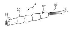
도 2는 본 발명에 따른 연결부재를 나타내는 사시도,2 is a perspective view showing a connecting member according to the present invention;
도 3은 도 2에 따른 연결부재의 다른 양태를 나타내는 구성도,3 is a configuration diagram showing another embodiment of the connecting member according to FIG. 2;
도 4는 본 발명에 따른 연결부재의 강체부 및 스페이서의 단면도,4 is a cross-sectional view of the rigid body portion and the spacer of the connecting member according to the present invention;
도 5는 본 발명에 따른 연결부재의 다른 양태를 나타내는 사시도,5 is a perspective view showing another embodiment of the connecting member according to the present invention;
도 6은 본 발명에 따른 연결부재의 또 다른 양태를 나타내는 사시도,6 is a perspective view showing another embodiment of the connecting member according to the present invention;
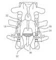
도 7은 본 발명에 따른 연결부재의 사용양태를 나타내는 구성도,Figure 7 is a block diagram showing the use of the connection member according to the invention,
도 8은 본 발명에 따른 연결부재의 또 다른 양태를 나타내는 사시도,8 is a perspective view showing another embodiment of the connecting member according to the present invention;
도 9는 본 발명에 따른 연결부재의 또 다른 양태를 나타내는 사시도,9 is a perspective view showing another embodiment of the connecting member according to the present invention;
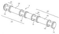
도 10은 본 발명에 따른 연결부재의 또 다른 양태를 나타내는 사시도,10 is a perspective view showing another embodiment of the connecting member according to the present invention;
도 11은 본 발명에 따른 연결부재의 또 다른 양태를 나타내는 사시도,11 is a perspective view showing another embodiment of the connecting member according to the present invention;
도 12는 본 발명에 따른 연결부재의 또 다른 양태를 나타내는 단면도이다.12 is a cross-sectional view showing another embodiment of the connecting member according to the present invention.
<도면의 주요부분에 대한 부호의 설명><Description of the symbols for the main parts of the drawings>
2 : 고정부재2' : 제 1 고정부재2: fixing member 2 ': first fixing member
2" : 제 2 고정부재4 : 로드, 연결부재2 ": second fixing member 4: rod, connecting member
6 : 클램프 샤프트 8 : 체결부6: clamp shaft 8: fastening part
10, 12 : 나사산14 : 고정수단10, 12: thread 14: fixing means
16 : 연결수단18 18' : 강체부16: connecting means 18 18 ': rigid body
20 : 스페이서(spacer) 22 : 연결홈20: spacer 22: connecting groove
24 : 돌출부26 : 삽입홈24: protrusion 26: insertion groove
28 : 금속부30 : 비금속부28: metal part 30: non-metal part
32, 32' : 척추분절34 : 디스크32, 32 ': Spine segment 34: disk
36 : 패쉿 조인트(facet joint)38 : 멜팅(melting)부36: facet joint 38: melting part
40 : 피복부40: covering part
본 발명은 척추의 질환을 치료하기 위한 척추 고정장치에 사용되는 로드(rod) 등의 연결부재에 관한 것으로서, 더욱 상세하게는 뼈에 삽입될 수 있는 스크류 모양의 고정부재 한 쌍 이상을 척추의 일측에 각각 삽입하여 고정시킨 후 상기 각각의 고정부재 상단의 체결부에 고정되어 상기 각각의 고정부재를 연결시키는 유연성을 갖는 연결부재에에 관한 것이다.The present invention relates to a connecting member such as a rod (rod) used in the spinal fixing device for treating a disease of the spine, and more particularly, one or more pairs of screw-shaped fixing members that can be inserted into a bone. It relates to a connecting member having a flexibility to be connected to each of the fixing member is fixed to the fastening portion of the upper end of each fixing member after being inserted and fixed to each.
퇴행성 추간반 질환(DDD, disc degenerative diseases)이나 척추강 협착증(spinal stenosis), 척추전방전위증(spondylolisthesis) 등과 같은 퇴행성 척추질 환은 보존적 치료에 호전이 없을 경우 수술적 치료를 필요로 하는데, 상기 수술적 치료는 먼저 감압(decompression)을 한 뒤 골유합(fusion, ALIF, PLIF 또는 posterolateral fusion)을 하고, 상기 골유합이 종료된 후 척추를 고정시키는 고정술을 하게 된다. 이때, 상기 수술 과정 중 일부의 경우 감압만 하거나 골유합술까지만 시술하기도 하지만 대부분의 경우 고정술까지 하게 된다.Degenerative spinal diseases such as disc degenerative diseases (DDD), spinal stenosis, spondylolisthesis, etc., require surgical treatment without improvement in conservative treatment. Treatment is decompression, followed by fusion (ALIF, PLIF or posterolateral fusion), and after the end of the union, fixation is performed to fix the spine. At this time, in some of the surgical procedures, only the decompression or bone fusion surgery may be performed, but in most cases, fixation is performed.
통상적으로 시술되는 고정술은 척추 고정장치를 이용하는데, 상기 척추 고정장치는 손상된 척추부를 정상적인 상태로 교정한 후 움직임 없이 고정할 수 있도록 척추골의 척추경 또는 천골에 소정의 강도와 깊이로 삽입되는 고정용 스크류와 척추부의 일측에 위치되는 로드 및 상기 로드와 고정용 스크류를 연계하여 체결하는 체결수단 등으로 구성되어 있다.Fixation is usually performed using a spinal fixation device, which is fixed to the vertebrae or sacrum of the vertebrae to be fixed at a predetermined strength and depth to fix the damaged vertebrae in a normal state without movement. It consists of a screw and a rod located on one side of the spine and a fastening means for fastening in conjunction with the rod and the fixing screw.
전술한 척추 고정장치의 일례로서 대한민국 특허공개 특2001-0047359호는 척추제의 척추경 또는 천골에 소정의 각도와 깊이로 삽입되며, 몸체 상부로는 중앙부가 관통되게 형성되고, 양측 내부에 체결부가 구비되며, 저면으로 안착부가 위치되고, 몸체 하측으로는 소정의 길이만큼 나선부가 구비된 고정용 스크류와 상기 고정용 스크류의 몸체 상부 저면 안착부에 위치되며, 손상된 척추부의 움직임을 방지할 수 있도록 소정의 길이와 직경을 갖고 몸체에는 결합수단이 형성된 로드와 상기 손상된 척추부의 움직임을 방지하기 위해 설치되는 로드와 고정용 스크류를 연계시켜 체결할 수 있도록 몸체 하측으로는 고정용 스크류의 체결부와 고정되는 체결구가 형성된 척추 고정장치가 개시되어 있으며, 대한민국 특허등록 제0324698호는 고정용 스크류에 고정되는 커넥터의 몸체 저면부에 구형의 회동구를 구비시키고 고정용 스크류와 상부커넥터와 하부커넥터가 차지하는 측면공간을 축소하여 시술의 편의성 및 작업성을 향상시킨 척추 고정장치가 개시되어 있으며, 미국특허출원 제6,193,720호에는 적어도 하나 이상의 스크류 상단에 로드 형태의 연결부재를 설치하여 척추를 고정시키는 척추 고정장치가 개시되어 있다.Republic of Korea Patent Publication No. 2001-0047359 as an example of the spinal fixation device described above is inserted into the pedicle or sacrum of the vertebrae at a predetermined angle and depth, the center portion is formed to penetrate the upper portion of the body, the fastening portion inside both sides It is provided, the seating portion is located on the bottom, the fixing screw is provided with a spiral portion to the lower side of the body and is located on the bottom seating portion of the upper surface of the upper body of the fixing screw, and to prevent the movement of the damaged spine Has a length and diameter of the body is fixed to the fastening portion of the fixing screw to the lower side of the body to be fastened by connecting the rod and the fixing screw is installed in order to prevent the movement of the damaged spine and the rod formed with a coupling means A spinal fixation device in which a fastener is formed is disclosed, and Korean Patent Registration No. 0324698 is fixed to a fixing screw The present invention discloses a spinal fixation device provided with a spherical pivoting hole at the bottom of a connector and reducing side space occupied by a fixing screw and an upper connector and a lower connector to improve the convenience and workability of the procedure. No. 6,193,720 discloses a spinal fixation device for fixing a spine by installing a rod-shaped connection member on at least one or more screws.
그러나, 상기 척추 고정장치에 사용되는 로드 등의 연결수단은 척추를 안정적으로 유지해주고, 비정상적인 움직임(abnormal movement)을 억제하여 불안정성으로 인하여 환자에게 발생하는 통증을 방지하고, 수술시 감압으로 약해진 척추를 보강하기 위하여 사용하는 것으로서, 척추의 상·하로 고정하여 척추간의 움직임을 허용하지 않으므로 장기간 사용할 경우 환자의 정상적인 움직임이 없어지며 상·하 척추관절에 이상이 오는 정션 증후군(junction syndrome) 또는 트랜지션널 증후군(transitional syndrome) 등의 부작용이 나타나는 문제점이 있다.However, the connecting means such as the rod used in the spinal fixing device maintains the spine stably, inhibits abnormal movements, prevents pain caused by the patient due to instability, and prevents the spine weakened by decompression during surgery. It is used to reinforce the upper and lower spine, which does not allow movement between the spine. Therefore, if long-term use does not allow the patient to move normally, the junction syndrome or transitional syndrome is abnormal in the upper and lower spine joints. Side effects such as transitional syndrome are present.
여기서, 감압이란 신경압박에 의하여 유발하는 통증을 해결하기 위해 척추의 일부 조직을 제거하여 척추강과 신경근을 보다 자유롭게 하는 것으로서, 상기 조직을 제거하게 되면 증상은 호전되지만 척추가 약해지는 문제점이 발생하고, 이를 보정하기 위하여 척추 고정장치를 사용한다.Here, decompression is to remove some tissues of the spine to free the spinal cavity and nerve roots in order to solve the pain caused by nerve compression, and when the tissue is removed, symptoms improve but the spine weakens. Spinal fixation is used to correct this.
특히, 전술한 척추 고정장치는 척추골에 삽입되는 고정수단 예를 들면 스크류 형태의 고정수단을 연결해 주는 로드는 강성(剛性)이 높으므로 수술 후 고정된 관절이 움직이지 않게 되어, 수술부위의 위 또는 아래에 위치한 척추관절의 움직임이 증가하여 척추의 불안정성을 초래하게 된다.In particular, the above-described spinal fixation device is a rod that connects the fixing means inserted into the vertebrae, for example, screw-type fixing means has a high rigidity (剛性) so that the fixed joints do not move after the operation, or above the surgical site The movement of the lower spinal joint increases, resulting in instability of the spine.
특히, 척추 고정장치를 이용한 시술에 대한 학계의 최근 보고에 의하면 지나 친 척추고정은 골유합에 도움이 되지 못하는 것으로 보고되고 있으며, 척추 고정장치의 시술 후 수술부위의 척추에 약간의 로드(load)가 가해지는 것이 오히려 골유합에 도움을 주는 것으로 알려져 있고, 일부에서는 시술한 척추의 상·하 척추관절을 움직일 수 있는 경우에 오히려 골유합에 도움이되는 것으로 보고되고 있는 실정이다.In particular, according to the recent reports of academics on the treatment using spinal fixation, excessive spinal fixation is not helpful for bone union, and there is a slight load on the spine of the surgical site after the spinal fixation. Rather, it is known that it helps bone union, and in some cases, the upper and lower spine joints of the treated spine are reported to be helpful for bone union.
전술한 문제점을 극복하기 위하여 골유합 후 고정술을 행하는 수술방법 대신 척추의 손상된 디스크 전체를 제거하는 인트라디스컬(intradiscal) 치료법, 상기 디스크를 인공 디스크로 치환하는 인공 디스크(artificial disc) 치료법 및 상기 디스크 구조물 중 수핵(nucleus)만을 대체하는 치료법 등이 개발되었으나, 상기 인트라디스컬 치료법은 최소 침습적이고 수술시간도 짧다는 장점이 있으나 치료의 성공률이 낮고, 인공 디스크를 이용한 치료법은 최근 들어 많이 적용되고 있으나 그 효과가 충분히 검증되지 못하였으며, 상기 수핵만을 대체하는 치료법은 현재까지 그 효과가 검증되지 못하였을 뿐만 아니라 퇴행성 추간반 질환의 일부에만 적용 가능하다는 문제점이 있다.In order to overcome the above-mentioned problems, intradiscal treatment for removing the entire damaged disk of the spine instead of surgery after bone fixation, artificial disc treatment for replacing the disk with an artificial disk, and the disk structure Treatments to replace only nucleus have been developed, but the intradiscal treatment has the advantages of minimally invasive and short operation time, but the success rate of treatment is low, and the treatment using artificial discs has been widely applied in recent years. The effectiveness has not been fully verified, and the treatment that replaces only the nucleus pulposus has a problem that the effect has not been verified to date and is applicable only to a part of the degenerative intervertebral disc disease.
그러므로 현재까지 척추질환에 사용되고 있는 로드 등을 이용한 척추 고정장치는 척추관련 질환을 치료하는데 있어서 주도적인 역할을 수행해오고 있으나, 수술 후 척추의 지나친 운동제한과 상·하 척추관절의 불안정성을 해결해야 하는 문제점이 있다.Therefore, spinal fixation devices using rods, which have been used for spinal diseases, have played a leading role in the treatment of spinal diseases, but they have to solve excessive movement limitation of spine and instability of upper and lower spinal joints after surgery. There is a problem.
이에, 본 발명자는 전술한 문제점을 극복하기 위하여 연구를 거듭하던 중 척추에 삽입되는 고정부재의 상단에 연결설치되는 로드를 유연한 구조 및/또는 재질 로 구성하여 상·하 척추관절을 움직일 수 있도록 할 수 있다는 점을 착안하여 본 발명을 완성하기에 이르렀다.Accordingly, the present inventors to configure the rod connected to the upper end of the fixing member inserted into the spine during the study to overcome the above-mentioned problems with a flexible structure and / or material to be able to move the upper and lower vertebral joints. The present invention has been completed by focusing on the fact that it can be used.
본 발명은 전술한 문제점을 해결하기 위하여 도출된 것으로서, 감압이 필요한 환자에게 감압 후 골유합을 하지 않고 바로 고정하는 방법을 사용할 수 있도록 하고, 척추의 비정상적인 움직임을 최소화하는 동시에 정상운동을 보존하며 인접 척추의 불안정성 유발을 최소화하기 위한 연결부재를 제공하는데 기술적 과제가 있다.The present invention was derived to solve the above-mentioned problems, to enable a patient to need a method of decompression immediately after decompression to the patient in need of decompression, while minimizing the abnormal movement of the spine while preserving normal movement and adjacent vertebrae There is a technical problem to provide a connecting member for minimizing the instability of the.
상기 목적을 달성하기 위한 본 발명은 척추 고정장치의 스크류 형태의 클램프 샤프트와 체결부를 포함하는 적어도 두 개 이상의 고정부재를 척추의 원하는 위치에 삽입하여 고정시킨 후 상기 각각의 고정부재를 연결하는 연결부재를 유연한 구조 및/또는 재질로 구성되도록 한다.The present invention for achieving the above object is at least two fastening members including a screw shaft and a fastening portion of the screw type of the spinal fixing device to insert the fixed position in the desired position of the spine and connecting the respective connecting members To be constructed of flexible structures and / or materials.
본 발명은 손상된 척추를 일정배열로 정열시킨 후 고정시켜 척추를 고정 및 교정할 수 있도록 척추에 삽입되어 체결되는 나사산이 형성된 스크류 형태의 클램프 샤프트 및 상기 클램프 샤프트의 상단에 연결설치되어 연결부재가 안착되어 체결되는 체결부로 구성된 적어도 두 개 이상의 고정부재와 상기 고정부재의 체결부에 삽입되어 고정되는 연결부재를 포함하는 척추 고정장치의 연결부재에 있어서, 상기 연결부재가 길이방향에 대하여 양쪽 말단에 강체부를 각각 구비시키고, 상기 각각의 강체부 사이에 중공을 갖는 하나 이상의 스페이서를 구비시키고, 길이방향으로 연장된 유연한 연결수단을 상기 스페이서의 중공을 통과시켜 상기 각각의 강체부에 연설치하여 연결부재의 길이방향으로 상기 각각의 강체부 사이에 스페이서가 실질적으로 고정되도록 구성된 것을 포함하는 척추 고정장치용 연결부재를 제공한다.The present invention is a screw-type clamp shaft and a screw-shaped clamp shaft that is inserted into the spine to be fixed and corrected by aligning and fixing the damaged vertebrae in a predetermined arrangement and connected to the upper end of the clamp shaft is seated In the connecting member of the spinal fixing device comprising at least two fixing members consisting of a fastening portion to be fastened and the connection member is inserted and fixed to the fastening portion of the fixing member, the connecting member is rigid at both ends with respect to the longitudinal direction And a plurality of spacers each having a hollow between the respective rigid bodies, and a flexible connecting means extending in the longitudinal direction through the hollows of the spacers to propagate the respective rigid portions to the rigid members. Spacers between the respective rigid portions in the longitudinal direction are substantially To provide a connection member for a spinal fixation device comprising constructed.
본 발명은 유연성을 갖는 척추 고정장치용 연결부재를 제공하기 위한 것으로, 상기 척추 고정장치는 통상적인 퇴행성 추간반 질환, 척추강협착증 또는 척추전방전위증 등과 같은 퇴행성 척추질환과 척추 불안정성을 유발하는 기타 척추를 고정 및 교정하기 위해 사용되는 것을 의미하며, 적어도 척추질환에 적용되어 척추에 삽입되어 고정될 수 있도록 스크류 형태를 갖는 고정부재와 상기 고정부재에 체결되어 상기 척추를 움직이지 않도록 하는 연결부재로 구성된다.The present invention is to provide a flexible connection member for the spinal fixation device, the spinal fixation device is a degenerative spinal disease such as degenerative intervertebral disc disease, spinal stenosis or spinal dislocation and other spine that causes spinal instability. Means to be used for fixing and correcting, it is composed of a fixing member having a screw shape so as to be inserted into the spine at least to be fixed to the spinal disease and a connecting member fastened to the fixing member so as not to move the spine. .
한편, 본 발명에 따른 연결부재는 척추에 삽입되어 고정된 고정부재의 일측에 연결설치되어 척추에 가해지는 하중을 견딜 수 있을 뿐만 아니라, 척추가 안정화되도록 고정시킬 수 있는 강도를 갖고, 척추의 움직임에 따라 일정하게 휘어질 수 있는 유연성을 갖는 것이라면 어떠한 것을 사용하여도 무방하며, 이러한 목적을 달성하기 위하여 당업계에서 통상적으로 사용되는 로드 등을 상기 연결부재로 이해할 수 있다.On the other hand, the connecting member according to the present invention is connected to one side of the fixed member is inserted into the spine can not only bear the load applied to the spine, but also has a strength that can be fixed to stabilize the spine, the movement of the spine According to the present invention, any one may be used as long as it has flexibility to be constantly bent, and a rod or the like commonly used in the art may be understood as the connecting member in order to achieve this object.
한편, 본 발명에 따른 연결부재는 척추에 삽입되어 고정된 고정부재의 일측에 연결설치되어 척추에 가해지는 하중을 견딜 수 있을 뿐만 아니라, 척추가 움직 이지 않도록 고정시킬 수 있는 강도를 갖고, 척추의 움직임에 따라 일정하게 휘어질 수 있는 재질 및/또는 구조라면 어떠한 것을 사용하여도 무방하다.On the other hand, the connecting member according to the present invention is connected to one side of the fixed member is inserted into the spine can not only bear the load applied to the spine, but also has a strength that can be fixed so that the spine does not move, Any material and / or structure that can be bent constantly according to movement may be used.
이와 같이 본 발명에 따른 척추 수술장치용 연결부재는 거시적인 관점에서 강성을 갖는 강체부(rigid end portion)를 상기 연결부재의 길이방향에 대하여 양쪽 말단에 구비시키고, 상기 각각의 강체부 사이에 강성을 갖는 또는 스페이서의 위치에 따라 강성과 유연성을 함께 갖는 스페이서(spacer)를 적어도 하나 이상 구비시켜 구성할 수 있다.As described above, the connecting member for the spinal surgery apparatus according to the present invention includes a rigid end portion having rigidity at both ends with respect to the longitudinal direction of the connecting member, and has rigidity between the respective rigid portions. It may be configured by having at least one or more spacers having both rigidity and flexibility depending on the position of the spacer.
이때, 상기 강체부 및 스페이서는 생체친화적인 금속, 생체친화적인 금속 및 생체친화적인 비금속 혼합물, 바람직하게는 생체친화적인 금속과 일정 부분이 생체친화적인 비금속으로 구성된 혼합물 또는 생체친화적인 금속 및 비금속 합성물로 이루어져 있는 바, 사용 가능한 생체친화적인 금속으로는 티타늄(titanium), 스테인레스 스틸(stainless steel), 지르코늄(zirconium), 탄탈(tantalum), 코발트(cobalt), 크롬(chromium), 니켈(nickel), 알루미늄(aluminum), 바나듐(vanadium) 또는 이들의 혼합물 또는 이들의 합금 등이 있고, 생체친화적인 비금속은 고분자(polymers), 엘라스토머(elastomers), 수지(resins), 세라믹(ceramics), 플라스틱(plastic), 카본 그래파이트(carbon graphite) 또는 이들의 혼합물 등이 있고, 상기 생체친화적인 금속 또는 생체친화적인 비금속은 이에 한정되는 것은 아니며, 당업계에서 본 발명에 따른 연결부재로 통상적으로 사용할 수 있는 것이라면 어떠한 것을 사용하여도 무방하다.In this case, the rigid portion and the spacer is a biocompatible metal, a biocompatible metal and a biocompatible nonmetal mixture, preferably a mixture composed of a biocompatible metal and a portion of the biocompatible nonmetal or a biocompatible metal and a nonmetal composite. The biocompatible metals that can be used include titanium, stainless steel, zirconium, tantalum, cobalt, chromium, nickel, Aluminum, vanadium, or mixtures thereof, or alloys thereof, and biocompatible nonmetals include polymers, elastomers, resins, ceramics, plastics, and the like. , Carbon graphite, or a mixture thereof, and the biocompatible metal or the biocompatible nonmetal is not limited thereto. As long as it can be commonly used as a connecting member according to the present invention in the art may be used any.
여기서, 상기 생체친화적인 금속 및 비금속 합성물은 전술한 생체친화적인 금속과 생체친화적인 비금속을 서로 합성(synthetic)한 것을 의미한다.Here, the biocompatible metal and the nonmetallic composite mean that the biocompatible metal and the biocompatible nonmetal described above are synthesized with each other.
한편, 전술한 재질로 이루어진 본 발명에 따른 강체부는 유연성을 갖는 연결수단에 의하여 스페이서에 연결설치되며, 그 일측이 척추 고정장치의 고정부재에 구비된 체결부에 삽입되어 체결될 수 있으므로 상기 체결부에 체결되어 고정될 수 있는 강성을 갖고, 상기 체결부에 용이하게 삽입될 수 있도록 원통형, 원기둥형, 봉형 등으로 이루어지는 것이 좋다. 그러나 그 형태는 상기 형태로 한정되는 것은 아니며, 상기 체결부에 삽입될 수 있는 어떠한 형태로 구성되어도 무방하다.On the other hand, the rigid body according to the present invention made of the above-described material is connected to the spacer by a connecting means having flexibility, one side of the fastening part because it can be inserted into the fastening part provided in the fixing member of the spinal fixing device It has a rigidity that can be fastened to be fixed to, it is preferable to be made of a cylindrical, cylindrical, rod-shaped, etc. to be easily inserted into the fastening portion. However, the form is not limited to the above form, and may be configured in any form that can be inserted into the fastening portion.
필요에 따라, 본 발명에 따른 강체부는 그 내부 중심에 중공이 형성되어 유연성을 갖는 연결수단이 삽입되어 고정될 수도 있고, 상기 강체부의 길이는 특별히 한정되는 것이 아니지만, 적어도 척추 고정장치의 체결부에 고정될 수 있는 정도의 길이를 갖는 것이 좋다.If necessary, the rigid part according to the present invention may be fixed by inserting a flexible connecting means having a hollow in the inner center thereof, the length of the rigid part is not particularly limited, but at least in the fastening portion of the spinal fixing device It is good to have a length that can be fixed.
그러나 상기 강체부가 척추 고정장치에 고정될 목적으로 존재하지 않고 스페이서를 관통하여 연결설치되는 연결수단을 고정하기 위해 존재할 경우 그 길이는 강체부의 직경보다 짧게 구성될 수도 있고, 특정적으로 원통형이 아닌 플레이트 형태로 존재할 수도 있다.However, if the rigid body is not intended to be fixed to the spinal fixation device but is present to fix the connecting means connected through the spacer, the length thereof may be configured to be shorter than the diameter of the rigid body, and in particular, a non-cylindrical plate. It may also exist in the form.
본 발명에 따른 스페이서는 한 쌍의 강체부 사이에 구비된 것으로서, 단독 또는 복수개로 사용될 수 있으며, 척추에 가해지는 외압을 견딜 수 있을 정도의 강성을 갖고, 그 형태는 이에 한정하는 것은 아니지만, 중공을 갖는 원통형, 중공을 갖는 원기둥형, 중공을 갖는 봉형 또는 링형 등의 구조로 구성된다.The spacer according to the present invention is provided between a pair of rigid bodies, and may be used alone or in plurality, and has a rigidity sufficient to withstand external pressure applied to the spine, and the shape thereof is not limited thereto. It is composed of a structure having a cylindrical shape, a cylindrical shape having a hollow, a rod shape having a hollow, or a ring shape.
특히, 본 발명에 따른 스페이서는 전술한 바와 같이 중공을 갖는 원통형, 중 공을 갖는 원기둥형, 중공을 갖는 봉형 또는 링형 등의 구조물을 단독으로 사용할 수 있지만, 필요에 따라 전술한 중공을 갖는 원통형, 중공을 갖는 원기둥형, 중공을 갖는 봉형 또는 링형 등의 구조물을 복수로 사용할 수 있으므로, 본원 발명에서는 적어도 하나 이상의 스페이서를 다수개 구비시켜 이루어진 것 전체를 스페이서로 간주할 수 있다. 이에, 본원 발명에서 언급되는 스페이서는 연결부재의 길이방향에 대하여 양쪽 말단에 위치하는 강체부 사이에 있는 구성을 스페이서로 이해할 수 있다.In particular, the spacer according to the present invention can be used alone, such as a cylindrical having a hollow, a cylindrical having a hollow, a rod-shaped or a ring having a hollow, as described above, if necessary, the cylindrical having a hollow, Since a plurality of structures such as a cylinder having a hollow, a rod or a ring having a hollow, and the like can be used in plural, in the present invention, the whole of at least one or more spacers can be regarded as a spacer. Thus, the spacer referred to in the present invention can be understood as a spacer between the rigid body portions located at both ends with respect to the longitudinal direction of the connecting member.
특정 양태로서, 본 발명에 따른 생체친화적인 금속과 생체친화적인 비금속 혼합물로 구성된 스페이서는 상기 생체친화적인 금속으로 이루어진 중공을 갖는 원통형, 중공을 갖는 원기둥형, 중공을 갖는 봉형 또는 링형 등의 구조물의 중공 내부 또는 상기 구조물의 중공 내부 및 외부에 생체친화적인 비금속을 충진 또는 피복한 형태로 구성될 수 있는 바, 본 발명에서는 상기 금속재질로 이루어진 구조물에 비금속재질이 충진 및/또는 피복된 형태를 특정적으로 메탈 하이브리드(metal hybrid)로 지칭하기로 한다.In a particular embodiment, a spacer composed of a biocompatible metal and a biocompatible nonmetal mixture according to the present invention comprises a cylindrical, hollow, cylindrical, hollow, rod or ring structure of the biocompatible metal. Bars may be formed in the form of filling or coating the bio-compatible non-metal in the hollow inside or the hollow inside and outside of the structure, in the present invention, the non-metal material is filled and / or coated in the structure made of the metal material It will be referred to as a metal hybrid (metal hybrid).
다른 특정 양태로서, 본 발명에 따른 스페이서는 강성을 갖는 금속, 바람직하게는 생체친화적인 금속으로 이루어진 금속부를 중심으로 양측에 비금속, 바람직하게는 생체친화적인 비금속으로 이루어진 비금속부가 한 쌍으로 형성되어 구성될 수 있으며, 필요에 따라 상기 금속부와 비금속부를 순차적으로 반복하여 연결설치한 형태로 구성될 수도 있다.In another specific embodiment, a spacer according to the present invention is constructed by forming a pair of nonmetal, preferably a biocompatible nonmetal, on a pair of nonmetal, preferably a biocompatible nonmetal, on both sides of a metal having rigidity, preferably a biocompatible metal. It may be, or may be configured in a form in which the metal part and the non-metal part are sequentially and repeatedly connected as necessary.
이때, 상기 금속부를 중심으로 양측에 연결설치되는 한 쌍의 비금속부의 재 질은 서로 다른 재질로 구성할 수 있고, 상기 스페이서를 구성하는 금속부는 필요에 따라 척추 고정장치의 고정부재에 연결설치될 수 있으며, 상기 스페이서를 구성하는 비금속부 및/또는 금속부의 외주면에 인체에 녹는 물질 예를 들면, 폴리락틱산(polylactic acid), 폴리글리콜릭산(polyglycolic acid), 폴리글락틱산(polyglactic acid), 폴리디옥산온(polydioxanone), 폴리글리코네이트(polyglyconate), 칼슘설페이트(calcium sulfate), 칼슘포스페이트(calcium phosphate) 또는 이의 혼합물 등을 피복하여 멜팅부를 형성시켜 스페이서를 구성할 수도 있다.In this case, the material of the pair of non-metal parts connected to both sides of the metal part may be formed of different materials, and the metal part constituting the spacer may be connected to the fixing member of the spinal fixing device as necessary. The non-metal part and / or metal part constituting the spacer may be dissolved in the human body, for example, polylactic acid, polyglycolic acid, polyglactic acid, polydi The spacer may be formed by forming a melting part by coating oxanone, polyglyconate, calcium sulfate, calcium phosphate, or a mixture thereof, and the like.
다른 양태로서, 본 발명에 따른 스페이서는 중공을 갖는 섹션부와 상기 섹션부에 연결설치된 중공을 갖는 비금속 섹션부로 구성될 수 있는 바, 상기 섹션부는 금속, 금속합금, 고분자, 수지, 플라스틱 또는 이들의 혼합물로 구성되어 있고, 상기 비금속 섹션부는 엘라스토머, 고분자, 수지, 플라스틱 또는 이들의 혼합물 등의 비금속으로 구성되어 있다.In another aspect, the spacer according to the present invention may be composed of a section having a hollow and a non-metal section having a hollow connected to the section, wherein the section has a metal, a metal alloy, a polymer, a resin, a plastic or a combination thereof. It is composed of a mixture, the non-metal section is composed of a non-metal, such as an elastomer, a polymer, a resin, a plastic or a mixture thereof.
이때, 상기 금속 및 금속합금으로 사용가능한 구체적인 물질은 티타늄, 스테인레스 스틸, 지르코늄, 탄탈, 코발트, 크롬, 니켈, 알루미늄, 바나듐 등의 생체친화적인 금속 및 이들로부터 선택되는 적어도 둘 이상의 금속합금 등이 있다.In this case, specific materials usable as the metal and the metal alloy include biocompatible metals such as titanium, stainless steel, zirconium, tantalum, cobalt, chromium, nickel, aluminum, vanadium, and at least two or more metal alloys selected from them. .
여기서, 상기 섹션부는 금속만으로 이루어질 수 있으며 이러한 경우, 상기 금속으로 이루어진 섹션부를 본 발명에 따른 금속부로 이해할 수 있고, 상기 비금속으로 이루어진 비금속 섹센부는 본 발명에 따른 비금속부로 이해할 수 있다.Here, the section portion may be made of only metal, and in this case, the section portion made of the metal may be understood as the metal portion according to the present invention, and the nonmetallic section portion made of the nonmetal may be understood as the nonmetal portion according to the present invention.
한편, 상기 섹션부가 금속만으로 이루어진 경우, 상기 섹션부는 비금속 섹션 부에 의하여 피복될 수 있고, 필요에 따라 상기 섹션부가 금속만으로 이루어져 있고 비금속 섹션부가 전술한 섹션부를 피복시키지 않도록 독립적으로 섹션부의 일측에 연결설치되면, 상기 섹션부를 구성하는 금속이 비금속으로 이루어진 비금속 섹션부의 일측을 덮도록 구성될 수 있다.On the other hand, when the section portion is made of only metal, the section portion may be covered by a non-metallic section portion, and if necessary, the section portion is made of only metal and is independently connected to one side of the section portion so that the non-metallic section portion does not cover the aforementioned section portion. When installed, the metal constituting the section portion may be configured to cover one side of the nonmetal section portion made of a nonmetal.
이때, 상기 섹션부를 피복시키는 비금속 섹션부의 재질은 엘라스토머를 사용하는 것이 좋다.At this time, it is preferable to use an elastomer as the material of the non-metal section covering the section.
또 다른 특정양태로서, 본 발명에 따른 스페이서는 그 내부 중심에 강성을 갖는 중공의 강체부를 구비하고, 상기 강체부를 중심으로 양측에 생체친화적인 비금속으로 이루어진 비금속부, 생체친화적인 금속으로 이루어진 금속부 및 생체친화적인 비금속부를 순차적으로 연결설치하여 구성될 수 있으며, 상기 강체부를 중심으로 양측에 연결설치되는 한 쌍의 비금속부의 재질 및 두께에 따라 연결부재의 유연성을 조절할 수 있도록 구성된다.In another specific embodiment, the spacer according to the present invention includes a hollow rigid body having rigidity at an inner center thereof, and a non-metallic portion made of a biocompatible nonmetal on both sides of the rigid portion, and a metallic portion made of a biocompatible metal. And it can be configured by connecting the bio-friendly non-metal parts sequentially, and configured to adjust the flexibility of the connection member according to the material and thickness of the pair of non-metal parts connected to both sides of the rigid body portion.
이때, 상기 강체부를 중심으로 양측에 연결설치되는 한 쌍의 비금속부 각각 및/또는 전체 비금속부 표면에 폴리락틱산, 폴리글리콜릭산, 폴리글락틱산, 폴리디옥산온, 폴리글리코네이트, 칼슘설페이트, 칼슘포스페이트 또는 이의 혼합물 등의 인체에 녹을 수 있는 재질로 피복된 멜팅부를 형성할 수 있다.At this time, the polylactic acid, polyglycolic acid, polylactic acid, polydioxanone, polyglyconate, calcium sulfate, Melting part coated with a material that can be dissolved in the human body, such as calcium phosphate or a mixture thereof may be formed.
본 발명에 따른 연결수단은 그 자체로 유연성을 갖는 동시에 본 발명에 따른 연결부재를 구성하는 강체부 및 스페이서를 연결하기 위한 것으로서, 상기 강체부 및 스페이서를 서로 연결설치할 수 있는 것이라면 어떠한 것을 사용하여도 무방하지만, 바람직하게는 척추의 움직임에 따라 소정량 휠 수 있는 성질을 갖기 위하여 휘어지는 성질을 갖는 재질로 구성되거나 강성이 높은 재질이라도 와이어 형태, 얇은 실 형태로 제조된 금속사를 포갠 와이어 형태, 편조선 형태 또는 샤프트 형태 등의 구조로 구성될 수 있다.The connecting means according to the present invention is intended to connect the rigid body portion and the spacer constituting the connecting member according to the present invention, while having flexibility in itself, as long as it can connect and install the rigid body portion and the spacer. Although it is preferable, even if the material consists of a material having a bending property or a rigid material in order to have a property that can be bent in a predetermined amount according to the movement of the spine, wire form, piece of metal yarn made of a wire form, thin thread form It may be of a structure such as ship form or shaft form.
더욱이, 본 발명에 따른 연결수단은 전술한 와이어, 금속사를 포갠 와이어, 편조선 형태 또는 샤프트 형태 등의 구조 이외에 그 재질로부터 유연성을 확보할 수 있는 바, 사용 가능한 재질로는 생체친화적인 금속, 적어도 생체친화적인 금속과 일정부분이 생체친화적인 비금속으로 구성된 혼합물 또는 생체친화적인 금속 및 비금속 합성물로 구성될 수 있고, 상기 생체친화적인 금속으로는 사용 가능한 물질로는 티타늄, 스테인레스 스틸, 지르코늄, 탄탈, 코발트, 크롬, 니켈, 알루미늄, 바나듐 또는 이들의 혼합물 또는 이들의 합금 등이 있고, 생체친화적인 비금속으로 사용 가능한 물질로는 고분자, 엘라스토머, 수지, 세라믹, 플라스틱, 카본 그래파이트 또는 이들의 혼합물 등이 있으며, 상기 생체친화적인 금속 또는 생체친화적인 비금속은 이에 한정되는 것은 아니며, 당업계에서 본 발명에 따른 연결부재로 통상적으로 사용할 수 있는 것이라면 어떠한 것을 사용하여도 무방하다.In addition, the connecting means according to the present invention can secure flexibility from the material in addition to the structure of the wire, metal yarn-wrapped wire, braided wire form or shaft form as described above, the material can be used biocompatible metal, It may be composed of a mixture of at least a biocompatible metal and a portion of the biocompatible nonmetal, or a biocompatible metal and a nonmetallic composite, and materials usable with the biocompatible metal include titanium, stainless steel, zirconium, and tantalum. , Cobalt, chromium, nickel, aluminum, vanadium, or mixtures thereof, or alloys thereof. Examples of materials that can be used as biocompatible nonmetals include polymers, elastomers, resins, ceramics, plastics, carbon graphite, or mixtures thereof. The biocompatible metal or biocompatible nonmetal is limited thereto. It is but may be used to any as long as they can, be used in a conventional connection to the member according to the present invention the art has not.
그러나 상기 생체친화적인 금속 또는 생체친화적인 비금속은 이에 한정되는 것은 아니며, 당업계에서 본 발명에 따른 연결부재로 사용할 수 있는 통상적인 물질이라면 어떠한 것을 사용하여도 무방하다.However, the biocompatible metal or biocompatible nonmetal is not limited thereto, and any material may be used as long as it is a conventional material that can be used as a connecting member according to the present invention in the art.
여기서, 상기 생체친화적인 금속 및 비금속 합성물은 전술한 생체친화적인 금속과 생체친화적인 비금속을 서로 합성한 것을 의미한다.Here, the biocompatible metal and the nonmetal composite mean that the biocompatible metal and the biocompatible nonmetal are synthesized with each other.
한편, 전술한 바와 같이, 한 쌍의 강체부, 상기 한 쌍의 강체부 사이에 적어 도 하나 이상 구비된 스페이서 및 상기 강체부와 스페이서를 서로 연결시켜 고정하는 연결수단을 포함하는 연결부재는 그 외부에 비금속재질의 피복물질로 피복된 피복부가 형성될 수 있는 바, 상기 피복부를 형성하는 피복물질은 스페이서 단독 또는 스페이서의 일부분 또는 복수의 스페이서 전체에 피복되어 피복부을 형성할 수 있다.On the other hand, as described above, the connection member including a pair of rigid body portion, at least one or more spacers provided between the pair of rigid body portion and the connecting means for connecting and fixing the rigid body portion and the spacer to each other outside thereof A coating part coated with a non-metallic coating material may be formed on the coating material. The coating material forming the coating part may be coated on the spacer alone or on a part of the spacer or the entire plurality of spacers to form the coating part.
이때, 상기 피복부를 구성하는 피복물질은 생체친화적인 비금속 예를 들면, 고분자, 엘라스토머, 수지, 세라믹, 플라스틱, 카본 그래파이트 또는 이들의 혼합물 등을 사용할 수 있다.In this case, the coating material constituting the coating portion may be a biocompatible non-metal, for example, a polymer, an elastomer, a resin, a ceramic, a plastic, carbon graphite or a mixture thereof.
이하, 본 발명에 따른 척추 고정장치용 연결부재를 첨부된 도면을 참조하여 상세히 설명하면 다음과 같다. 그러나 하기의 설명은 오로지 본 발명을 구체적으로 설명하기 위한 것으로 하기 설명에 의해 본 발명의 범위를 한정하는 것은 아니다.Hereinafter, with reference to the accompanying drawings, the connection member for a spinal fixing device according to the present invention will be described in detail. However, the following description is only for describing the present invention in detail and does not limit the scope of the present invention by the following description.
도 1은 본 발명에 따른 척추 고정장치의 사시도, 도 2는 본 발명에 따른 연결부재를 나타내는 사시도, 도 3은 도 2에 따른 연결부재의 다른 양태를 나타내는 구성도, 도 4는 본 발명에 따른 연결부재의 강체부 및 스페이서의 단면도, 도 5는 본 발명에 따른 연결부재의 다른 양태를 나타내는 사시도, 도 6은 본 발명에 따른 연결부재의 또 다른 양태를 나타내는 사시도, 도 7은 본 발명에 따른 연결부재의 사용양태를 나타내는 구성도, 도 8은 본 발명에 따른 연결부재의 또 다른 양태를 나타내는 사시도, 도 9는 본 발명에 따른 연결부재의 또 다른 양태를 나타내는 사 시도, 도 10은 본 발명에 따른 연결부재의 또 다른 양태를 나타내는 사시도, 도 11은 본 발명에 따른 연결부재의 또 다른 양태를 나타내는 사시도, 도 12는 본 발명에 따른 연결부재의 또 다른 양태를 나타내는 단면도로서 함께 설명한다.1 is a perspective view of a spinal fixation apparatus according to the present invention, Figure 2 is a perspective view showing a connecting member according to the present invention, Figure 3 is a configuration diagram showing another aspect of the connecting member according to Figure 2, Figure 4 is according to the present invention Fig. 5 is a perspective view showing another embodiment of the connection member according to the present invention, Fig. 6 is a perspective view showing another embodiment of the connection member according to the present invention, and Fig. 7 is a view according to the present invention. 8 is a perspective view showing another embodiment of the connection member according to the present invention, Figure 9 is a view showing another embodiment of the connection member according to the present invention, Figure 10 is a present invention 11 is a perspective view showing another embodiment of the connecting member according to the present invention, FIG. 11 is a perspective view showing another embodiment of the connecting member according to the present invention, and FIG. 12 is another aspect of the connecting member according to the present invention. It will be described with a cross-sectional view shown.
도 1 내지 도 12에 도시된 바와 같이, 본 발명에 따른 연결부재(4)가 사용되는 척추 고정장치는 크게 척추의 척추경에 삽입되어 고정되는 적어도 두 개 이상의 고정부재(2)와 적어도 하나 이상의 연결부재(4)로 이루어져 있다.As shown in Figures 1 to 12, the spinal fixing device using the connecting
이에, 상기 고정부재(2)를 한 쌍으로 사용할 경우로 본 발명에 따른 척추 고정장치를 설명하면, 상기 한 쌍의 고정부재(2) 중 임의로 하나의 고정부재를 제 1 고정부재(2')로 하고, 다른 하나를 제 2 고정부재(2")로 할 때, 상기 제 1 고정부재(2')와 제 2 고정부재(2")의 일측에 체결되어 상기 제 1 고정부재(2') 및 제 2 고정부재(2")가 용이하게 움직이지 않도록 하는 연결부재(4)로 구성된다.Thus, when using the fixing
여기서, 상기 고정부재(2)는 본 발명에 따른 연결부재(4)와 체결되어 함께 사용되고, 척추에 삽입되어 고정될 수 있는 장치라면 어느 것을 사용하여도 무방하며, 당업계에서 통상적으로 사용되고 있는 척추 고정장치의 고정부재(2)라면 어느 것을 사용하여도 좋다.Here, the fixing
한편, 상기 고정부재(2)는 척추에 삽입되어 체결될 수 있도록 그 하단으로 나사산(10, 12)이 형성되어 있고, 상기 나사산(10, 12)의 말단으로 척추에 삽입될 수 있는 모양인 뾰족한 원추형태로 마감된 스크류 형태의 클램프 샤프트(6) 및 상기 클램프 샤프트(6)의 상단에 연결설치되어 상기 연결부재(4)가 안착되어 체결되 는 체결부(8)로 구성되어 있다.On the other hand, the fixing member (2) has a thread (10, 12) is formed at its lower end so that it can be inserted into the spine, the pointed shape that can be inserted into the spine to the end of the thread (10, 12) It consists of a clamp shaft (6) in the form of a conical finish and a fastening portion (8) connected to the upper end of the clamp shaft (6) to be seated and fastened.
본 발명에 따른 연결부재(4)는 길이방향에 대하여 양쪽 말단에 강체부(18)를 구비시키고, 상기 각각의 강체부(18) 사이에 하나 이상의 스페이서(20)를 구비시키고, 상기 강체부(18) 및 스페이서(20)를 유연한 연결수단(16)으로 연결하여 로드의 길이방향으로 상기 각각의 강체부(18) 사이에 스페이서(20)가 실질적으로 고정되도록 구성된다.The connecting
필요에 따라, 본 발명에 따른 스페이서(20)는 그 내부에 중공이 형성되어 있고, 상기 중공을 관통하여 연결수단(16)이 연결설치되고, 이러한 연결수단(16)은 유연성을 갖기 위하여 유연한 재질 및/또는 구조로 구성되어 있는 바, 이를 구체적으로 설명하면, 도 2 및 도 3에 도시된 바와 같이, 한 쌍의 강체부(18, 18')를 연결부재(4)의 양측 말단에 각각 구비시킨 후 상기 각각의 강체부(18, 18') 사이에 중공을 갖는 적어도 하나 이상의 스페이서(20)를 연결설치할 수 있도록 구성된다.If necessary, the
이때, 본 발명에 따른 연결부재(4)를 구성하는 스페이서(20)가 다수개 구비될 경우, 상기 강체부(18) 및 스페이서(20)는 그 길이방향에 대하여 일측 말단에 내부로 오목한 형태의 연결홈(22)이 형성되어 있고, 상기 연결홈(22)의 대향되는 타측 말단으로 다른 강체부(18) 또는 스페이서(20)에 형성되어 있는 연결홈(22)에 삽입되어 맞물리도록 외부로 돌출된 돌출부(24)가 형성되게 구성할 수도 있다.At this time, when a plurality of
전술한 구성을 갖는 본 발명에 따른 연결부재(4)는 필요에 따라, 도 5에 도시된 바와 같이 상기 강체부(18) 일측에 연결수단(16)을 삽입하여 강체부(18) 및 스페이서(20)를 서로 연결할 수 있도록 삽입홈(26)을 더 구비할 수 있으며, 이와 같은 구성은 연결부재(4)의 길이를 환자마다의 해부학적 특성에 따라 적용할 수 있도록 수술현장에서 조절하여 다르게 구성 할 수도 있다.
다른 양태로서, 본 발명에 따른 연결부재(4)는 상기 연결부재(4)를 구성하는 와이어 형태의 연결수단(16)을 금속클립(metallic clip) 또는 스토퍼(stopper)를 사용하여 고정할 수도 있는 바, 예를 들면 상기 금속클립 또는 스토퍼를 와이어 형태의 연결수단(16)이 통과할 수 있도록 연결수단(16) 보다 약간 큰 지름을 가진 내부지름으로 구성된 작은 원통형 형태를 포함할 수 있다.In another aspect, the connecting
여기서, 상기 금속클립 또는 스토퍼는 당업계에서 통상적으로 사용되는 것이라면 어떠한 것을 사용하여도 무방하다.Here, the metal clip or stopper may be used as long as it is commonly used in the art.
이때, 상기 연결부재(4)를 구성하는 강체부(18) 및 스페이서(20)를 서로 고정시키는 것은 상기 연결수단(16)을 스토퍼를 통해 원하는 정도까지 팽팽히 당긴 후 상기 스토퍼를 스페이서(20)와 스페이서(20) 사이 또는 스페이서(20) 말단 일측에 밀어 넣어 고정시키거나 미리 스페이서(20)의 숫자를 결정한 다음 연결부재(4)를 제작할 때 와이어 형태의 연결수단(16)을 단단하게 고정할 수도 있다.At this time, fixing the
다른 양태로서, 본 발명에 따른 연결부재(4)는 도 6에 도시된 바와 같이, 길이가 다른 한 쌍의 강체부(18, 18') 사이에 중공을 갖는 스페이서(20)를 설치하고, 상기 스페이서(20)의 중공에 유연한 재질 및/또는 구조의 연결수단(16)을 스페이서(20) 및 강체부(18)의 중공에 삽입하여 구성할 수 있다.In another aspect, the connecting
여기서, 상기 스페이서(20)는 생체친화적인 금속, 생체친화적인 금속 및 비금속의 혼합물 또는 생체친화적인 금속 및 비금속 합성물을 사용할 수 있지만, 추 천하기로는 생체친화적인 금속 및 비금속의 혼합물인 메탈 하이브리드를 사용하는 것이 좋다.Here, the
이때, 상기 스페이서(20)는 강성을 갖는 금속으로 이루어진 금속부(28)를 중심으로 양측에 비금속으로 이루어진 비금속부(30)를 설치하여 구성될 수 있다.In this case, the
또 다른 양태로서, 본 발명에 따른 연결부재(4)는 강체부(18)를 중심으로 양측에 스페이서(20)를 형성시킬 수 있다. 이때, 상기 스페이서(20)는 금속으로 이루어진 금속부(28) 및 비금속으로 이루어진 비금속부(30)를 순차적으로 반복설치하여 구성할 수 있다.As another aspect, the connecting
전술한 모든 양태에 있어서, 메탈 하이브리드 스페이서(20)를 적어도 하나의 금속과 비금속으로 구성하여 금속으로 구성된 스페이서(20)의 금속부(28)가 고정장치의 체결부(8) 바람직하게는 스크류나 라미나 후크(lamina hook) 등이 형성되어 있는 고정부재에 체결되어 고정되도록 하고, 엘라스토머 등의 비금속으로 이루어진 스페이서(20)의 비금속부(30)는 상기 금속부(28)의 반대방향과 인접하고 있는 각각의 강체부(18, 18')의 말단과 중간의 유연한 연결수단(16)에 연결설치되도록 한다.In all the above-described embodiments, the
또한, 본 발명에 따른 연결부재(4)는 강체부(18)의 일측 말단과 스페이서(20)의 금속부(28)가 척추 고정장치의 체결부(8)에 고정되어 허리 분절에 부착됨으로써 상기 연결부재(4)가 고정된 허리분절의 하중을 견디면서 동시에 여섯 가지 방향의 움직임 예를 들면, x축(x-axis), y축(y-axis), z축(z-axis), 피치(pitch) 또는 회전 및 편요(偏搖)(roll and yaw) 방향으로의 움직임을 갖도록 한다.In addition, the connecting
이때, 상기 연결부재(4)는 스페이서(20)의 종축방향 움직임이 제한될 수 있 지만, 상기 스페이서(20)의 양쪽에 위치하는 엘라스토머 등으로 이루어진 비금속부(30)에 의하여 압축력과 인장력이 연결부재(4)의 양쪽 말단에 위치하는 강체부(18, 18')의 내부에 전달됨으로써 유연성을 갖도록 유연한 재질 및/또는 구조로 이루어진 연결수단(16)이 위치하는 방향에서 상대적으로 안정된 움직임을 허용하도록 구성된다.At this time, the connecting
또 다른 양태로서, 본 발명에 따른 연결부재(4)는 마찰력이 큰 물질을 이용하여 엘라스토머 등으로 이루어진 비금속부(30)를 피복함으로써 스페이서(20)의 유연한 연결수단(16)의 움직임을 억제하도록 구성할 수 있다. 여기서, 강체부(18, 18')는 중간의 연결수단(16)을 이용하여 스페이서(20) 바람직하게는 메탈 하이브리드로 이루어진 스페이서(20)에 연결설치된다.As yet another aspect, the connecting
여기서, 상기 연결수단(16)은 상기 강체부(18)에 영구적으로 고정되는 강성을 갖는 재질로 이루어져 있고, 특정적으로 와이어 형태 또는 다수개의 금속사를 꼬여 만든 와이어 형태, 편조선 형태 또는 샤프트 형태 등의 구조로 구성될 수도 있으며, 그 재질 및 구조는 이에 한정되는 것이 아니라 그 구조, 길이 및/또는 두께를 변경함에 따라 상기 연결수단(16)의 유연성을 변경할 수 있다.Here, the connecting
또한, 본 발명에 따른 연결부재(4)를 구성하는 강체부(18)의 일측 말단은 척추 고정장치의 체결부(8) 등에 체결될 수 있도록 충분한 길이를 갖도록 형성되며, 상기 메탈 하이브리드 재질을 갖는 스페이서(20)의 금속부(28)가 척추 고정장치의 고정부재에 체결될 경우, 상기 연결부재(4)의 강체부(18')의 일측 말단은 고정부재(2)의 체결부(8)의 외측으로 연장되도록 설치되며, 이러한 경우 체결부(8)의 외측 으로 연장되는 부분의 길이를 감소시키기 위해 상기 고정부재(2)의 체결부(8)에 연결설치되는 연결부재(4)의 강체부(18)에 대향되는 타측 강체부(18')의 길이를 보다 짧게 구성하게 된다.In addition, one end of the
또 다른 양태로서, 본 발명에 따른 유연한 재질 및/또는 구조의 연결수단(16)이 연결부재(4)의 중앙 종축방향으로 같은 동심원이 아닌 형태 즉, 연결수단(16)이 스페이서(20)의 중심점이 아닌 지점을 지나도록 연결설치되는 형태로 구성될 수 있다. 이와 같이 다른 동심원 구조를 갖는 연결부재(4)는 굽혀지는 방향에 따라 다른 정도의 유연성을 가지게 되며, 이는 연결부재(4)가 굽혀지거나 휠 때 예를 들면 환자의 허리가 앞으로 굽혀짐에 따라 보다 큰 강성을 가지게 되고, 상기 연결부재(4)가 반대로 휠 때 예를 들면 환자의 허리가 뒤로 굽혀짐에 따라 강성이 감소되는 장점을 갖게 된다.In a further aspect, the connecting means 16 of the flexible material and / or structure according to the invention is of the same concentric shape in the central longitudinal direction of the connecting
한편, 상기 연결부재(4)의 일측에 형성되는 엘라스토머 등의 재질로 이루어진 비금속부(30)의 경우 상기 비금속부(30)를 형성시키기 위하여 피복하는 비금속의 두께나 양에 따라 연결부재(4)의 굽혀지는 방향이나 강성을 조절할 수 있다.On the other hand, in the case of the
여기서, 상기 비금속부(30)는 연결부재(4)의 스페이서(20)의 움직임에 따라 각기 다른 방향성과 다른 정도의 강성을 주며, 상기 스페이서(20)를 통해서 고정부재(2)에 고정되는 분절의 움직임에 각기 다른 방향성을 부여하게 된다.Here, the
한편, 본 발명에 따른 연결부재(4)는 환자의 허리에 고정하기 전에 올바른 위치에 연결되도록 굽히는 방향과 알맞은 강성을 식별하기 위한 표시 예를 들면 레이저 또는 물리적 표시를 삽입할 수 있다.On the other hand, the connecting
전술한 연결부재(4)의 용이한 설명을 위하여 그 작용방법을 설명하면, 본 발명에 따른 연결부재(4)는 도 7에 도시된 바와 같이 두개의 연결부재(4)를 환자의 척추에 삽입되어 고정된 고정부재(2)에 각각 연결설치하여 사용된다.Referring to the method of operation for easy description of the above-described
이때, 상기 각각의 연결부재(4)는 환자의 척추에 적용되어 각각 필요한 분절에 위치하게 되며, 각각의 연결부재(4)를 구성하는 스페이서(20)는 하위의 척추분절(32')에 체결되고 강체부(18)의 일측 말단은 상위의 척추분절(32)에 체결되도록 한다.At this time, each of the connecting
이와 같은 구성으로 적용되는 연결부재(4)는 척추의 해부학적 및 원래대로 회귀하고자 하는 움직임을 허용하기 위해 고려된 것으로서, 척추분절(32, 32') 사이에 있는 디스크(34)와 인페리어 패쉿 조인트(Inferior facet joint)(36)가 상위 척추분절(32) 보다 하위 척추분절(32')에 근접하기 때문에 상기 연결부재(4) 중 메탈 하이브리드 재질로 이루어진 스페이서(20)를 하위 척추분절(32')에 구비된 고정부재(2)에 연결설치할 때, 상기 연결부재(4)의 유연한 구조부분이 척추가 지니고 있는 본래의 움직임을 제공하는 축, 예를 들면 척추간 디스크(34)와 패쉿 조인트(36) 등의 위치의 축과 일치하거나 가장 근접하게 위치하게 된다. 그러므로 상기 본래의 척추분절 움직임과 같은 위치에서 제공되는 유연성으로 인해 척추에 자연스러운 해부학적 움직임을 허용하게 된다.The connecting
한편, 전술한 위치 이외의 척추부분에서 유연성을 요구하는 경우에는 상기 메탈 하이브리드 재질로 이루어진 스페이서(20)와 연결수단(16)을 강성을 갖는 강체부(18)를 중심으로 양측에 연결설치하여 연결부재(4)를 구성하고, 상기 강체부 (18) 양측에 연결설치된 메탈 하이브리드 재질로 이루어진 스페이서(20)의 금속부(28)에 각각에 척추 고정장치가 체결되도록 구성된다.On the other hand, when flexibility is required at the spine other than the above-described position, the
이때, 상기 연결부재(4)의 스페이서(20)는 연결부재(4)에서 보다 길게 연장되도록 구성되어 환자들의 척추분절(32, 32')간의 길이에 따라 조절 가능하도록 구성된다.At this time, the
또 다른 양태로서, 본 발명에 따른 연결부재(4)는 셋 이상의 척추간 분절에 고정되어 상기 척추간 분절에 움직임을 허용하도록 구성될 수 있는 바, 이러한 연결부재(4)이 일예로서, 중공을 갖는 강체부(18)를 중심으로 양측에 비금속으로 이루어진 비금속부(30), 금속으로 이루어진 금속부(28) 및 비금속부(30)를 순차적으로 연결설치 한 후 전술한 구성을 반복적으로 연결설치하거나, 한 쌍의 강체부(18) 사이에 구비되는 스페이서(20) 및 상기 스페이서(20)와 강체부(18)을 연결시켜 실질적으로 고정하는 연결수단(16)으로 구성된 연결부재(4)를 복수로 연결설치하여 하나의 연결부재(4)를 구성할 수 있다.In another aspect, the connecting
다수의 척추분절에 적용되는 연결부재(4)의 또 다른 양태로서, 척추 고정장치를 이용한 척추수술의 시술자들은 필요에 따라 메탈 하이브리드 재질의 스페이서(20) 중 어느 하나가 강체부(18)로 대체되거나 여러 가지 조합 형태로 구성될 수 있는 바, 이러한 방법을 통해서 스페이서(20)를 가진 한 분절의 연결부재(4)를 반복하여 설치하거나 스페이서(20)의 강체부를 필요에 따라 여러 가지 방법으로 조합하여 각 분절에 필요한 정도의 강성을 갖도록 하여 각각의 상·하 척추분절(32, 32')에 필요한 움직임을 조절하도록 구성될 수 있다.As another aspect of the connecting
이러한 일례로서, 첫 번째 척추분절에 적용되는 연결부재(4)는 두 번째 척추 분절에 적용되는 연결부재(4) 보다 비교적 덜 유연하게 구성될 수 있도록 함으로써 다양한 조합을 통해 각기 다른 정도의 유연성을 갖는 다분절용 척추 고정장치용 연결부재(4)를 제조할 수 있다.As an example of this, the connecting
한편, 본 발명에 따른 연결부재(4)로 도시된 도 6 내지 도 8에 따른 연결부재(4)는 유연성을 갖기 위하여 유연한 재질 및/또는 구조로 구성된 연결수단(16)을 생체친화적인 금속, 바람직하게는 강체부(18)를 구성하는 생체친화적인 금속과 동일유사한 재질로 이루어지도록 구성하는데, 추천하기로는 상기 강체부(18)에 영구적으로 고정되는 비교적 단단한 재질로 이루어져 있고, 특정적으로 와이어 형태 또는 다수개의 금속사를 꼬여 만든 와이어 형태, 편조선 형태의 구조 또는 샤프트 형태 등으로 구성될 수 있고, 그 재질 및 구조는 전술한 내용에 한정되는 것은 아니며, 그 구조, 길이 및/또는 두께를 변경에 따라 연결수단(16)의 유연성을 변경할 수 있다.On the other hand, the connecting
또한, 상기 메탈 하이브리드 재질의 스페이서(20)는 생체친화적인 금속, 바람직하게는 연결부재(4)의 양끝 말단에 위치하는 강체부(18)와 동일한 재질 및 생체친화적인 비금속 예를 들면, 실리콘 또는 폴리우레탄, 바람직하게는 폴리카보네이트 우레탄 등의 비금속으로 구성될 수 있고, 상기 메탈 하이브리드로 이루어진 스페이서(20)는 강체부(18)의 직경과 동일한 직경으로 구성되고, 그 스페이서(20)를 구성하는 엘라스토머 등을 포함하는 비금속부(30)는 상기 강체부(18)의 직경보다 작거나 클 수 있다.In addition, the
필요에 따라, 본 발명에 따른 연결부재(4)는 상기 연결부재(4)의 외부표면을 비금속 등으로 피복하여 유연성을 조절할 수 있도록 구성되는 바, 상기 비금속 등의 피복물질의 종류와 치수에 따라 연결부재(4)의 유연성을 조절할 수도 있다.If necessary, the connecting
또한, 본 발명에 따른 메탈 하이브리드 재질을 포함하는 스페이서(20)의 비금속 또는 엘라스토머 등으로 이루어진 비금속부(30)는 강체부(18)와 금속재질로 이루어진 금속부(28) 또는 유연한 재질 및/또는 구조의 연결수단(16)에 고정되도록 구성될 수 있다.In addition, the
이러한 양태로서, 도 6 내지 도 9에 도시된 바와 같이 엘라스토머로 이루어진 또는 엘라스토머가 충진 및/또는 피복되어 이루어진 비금속부(30)는 금속부(28)를 강체부(18)가 위치하는 방향으로 고정하여 유지됨으로써 외부의 힘에 의해 엘라스토머를 포함하는 비금속부(30)가 어느 방향으로 굽혀지거나 압축될 때 상대적인 움직임을 허용하도록 유지할 수도 있다.In this embodiment, as shown in FIGS. 6 to 9, the
또 다른 양태로서, 스페이서(20)의 금속부(28)가 고정부재(2)에 체결되어 상기 금속부(28)의 움직임에 의한 스페이서(20)의 비금속부(30) 압축력이 상당히 제한되면서 다양한 방향의 움직임을 통해 연결부재(4)의 유연성을 조절할 수 있도록 구성될 수도 있다.In another embodiment, the
또 다른 양태로서, 본 발명에 따른 연결부재(4)는 도9에 도시된 바와 같이, 메탈 하이브리드 재질을 포함하는 스페이서(20)가 적어도 두 가지 이상의 물질로 구성될 수 있는 바, 이는 스페이서(20)의 금속부(28)와 엘라스토머 등으로 이루어진 비금속부(30)로 구성되어 상기 엘라스토머 등의 재질로 이루어진 비금속부(30) 의 외측에 추가로 생체에서 녹을 수 있는 재질로 구성된 멜팅부(40)를 구비할 수 있다.As another aspect, the connecting
여기서, 상기 인체에 녹을 수 있는 재질로 이루어진 멜팅부(38)는 금속재질로 이루어진 스페이서(20)의 금속부(28)의 말단 일측에 인접한 강체부(18)에 형성되어 인체 내에서 녹아 부드러워질 때까지 상기 금속부(28)의 움직임을 일정하게 제한하도록 한다.Here, the melting part 38 made of a material that can be melted in the human body is formed in the
전술한 멜팅부(38)로 사용가능한 물질은 인체에 무해하며, 인체내에서 녹을 수 있는 물질이라면 어떤 것을 사용하여도 무방하지만, 바람직하게는 폴리락틱산, 폴리글리콜릭산, 폴리글락틱산, 폴리디옥산온, 폴리글리코네이트, 칼슘설페이트, 칼슘포스페이트 또는 이의 혼합물을 사용할 수 있으며, 현재까지 발견되지 않은 어떠한 물질이라도 인체 내에서 녹을 수 있는 물질은 본 발명의 멜팅부(38)로 사용될 수 있다.The material usable as the above-described melting part 38 may be used as long as it is harmless to the human body and may be used as long as it can be dissolved in the human body. Preferably, the polylactic acid, polyglycolic acid, polyglycolic acid, polydi Oxanone, polyglyconate, calcium sulfate, calcium phosphate or mixtures thereof may be used, and any material that has not been found so far may be used as the melting part 38 of the present invention.
특히, 본 발명에 따른 유연한 연결수단(16)은 다양한 레벨의 역동적 고정을 필요로 하는 경우에 적용될 수 있다는 장점이 있으며, 엘라스토머 등의 비금속 양과 멜팅부(38)를 구성하는 인체에 녹을 수 있는 물질의 양을 조절하여 구성함으로써 연결수단(16)의 최초 유연성을 조절하고, 시간의 흐름에 따라 상기 멜팅부(38)를 구성하는 물질이 인체 내로 녹아 들어감으로써 초기에 연결부재(4)가 갖는 유연성과 다른 유연성을 얻을 수 있으며, 이는 전술한 바와 같이 3분절 이상의 고정이 필요한 다분절 척추고정에서도 활용될 수 있다.In particular, the flexible connecting
또한, 상기 인체에 녹을 수 있는 물질이 메탈 하이브리드를 포함하는 스페이 서(20)를 전부 또는 일부를 둘러싸는 형태로 피복되거나 스페이서(20)와 연결수단(16)에 형성되어 있는 틈만을 메우는 등의 다양한 방법에 의하여 연결부재(4)의 최초 유연성과 멜팅부(38)를 구성하는 물질이 인체에 녹은 후의 연결부재(4) 유연성의 차이를 조절할 수 있다.In addition, the material that can be dissolved in the human body is covered in a form that surrounds all or part of the
이는 엘라스토머 등으로 구성된 스페이서(20)의 비금속부(30) 전부가 인체 내에서 녹을 수 있는 물질로 대체되어 유연성을 조절할 수 있는 것으로, 이처럼 다양한 조합구성을 통하여 원하는 정도의 유연성을 연결부재(4)에 부여할 수 있다.This is because all of the
본 발명에 따른 연결부재(4)의 또 다른 양태로서, 도 10에 도시된 바와 같이 중공을 갖는 한 쌍의 강체부(18) 사이에 중공을 갖는 스페이서(20)를 구비시키고, 상기 강체부(18) 및 스페이서(20)의 중공에 와이어 형태의 연결수단(4)을 삽입하여 서로 고정시킨 것으로서, 상기 스페이서(20)의 외부에 엘라스토머 등의 비금속을 피복하여 피복층(40)을 형성시켜 구성할 수 있다.As another aspect of the connecting
여기서, 상기 스페이서(20)가 각각의 강체부(18) 사이의 공간을 모두 점유하여 스페이서(20)가 각각의 강체부(18) 사이에 고정되는 것으로서, 강체부(18)와 스페이서(20) 사이에 공간이 존재하지 않으므로 스페이서(20)가 와이어 형태의 연결수단(16)에 의해 움직이거나 미끄러지지 않게 된다. 즉, 각각의 스페이서(20)는 스페이서(20) 끼리 그리고 강체부(18)와 서로 인접하여 중간에 있는 와이어 형태의 연결수단(16)에서 미끄러질 공간이 존재하지 않게 된다.Here, the
필요에 따라, 상기 피복부(40)는 상기 스페이서(20) 단독으로 또는 상기 스페이서(20) 전체를 피복하여 형성될 수 있고, 전술한 피복부(40)와 스페이서(20)의 조합으로 인하여 각 스페이서(20) 마다 다른 물질을 피복하여 서로 다른 물질로 피복된 스페이서(20)를 구성할 수도 있다.If necessary, the covering
한편, 상기 스페이서(20)는 생체친화적인 금속 또는 금속과 비금속의 혼합물로 제조될 수 있고, 상기 피복부(40)는 생체친화적인 비금속 또는 이의 혼합물 또는 합성물, 바람직하게는 엘라스토머 등으로 제조될 수 있다.Meanwhile, the
본 발명에 따른 연결부재(4)의 또 다른 양태로서, 도 11에 도시된 바와 같이 하나의 스페이서(20)에 인접한 다른 스페이서(20)와 연결부재(4)의 말단을 구성하는 강체부(18) 사이에 공간이 없도록 와이어 형태의 연결수단(16)을 연결설치한 것으로서, 피복부(40)가 스페이서(20)와 연결수단(16)의 주변에 형성되어 인접한 스페이서(20)와 강체부(18) 사이의 공간이 모두 피복하도록 구성된다.As another aspect of the connecting
이와 같은 구성을 갖는 연결부재(4)는 피복부(40)가 피복물질로 둘러싸인 연결수단(16) 및 스페이서(20)의 움직임을 제한하여 한 쌍의 강체부(18) 사이의 유연한 부분에 추가적인 강성을 제공할 수 있다.The connecting
여기서, 상기 스페이서(20) 및/또는 연결수단(16)은 생체친화적인 금속, 비금속 또는 금속 및 비금속의 혼합물로 이루어져 있으며, 상기 피복부(40)는 피복에 적합한 생체친화적인 비금속을 사용하는 것이 좋고, 추천하기로는 엘라스토머가 좋다.Here, the
한편, 상기 도 10 및 도 11에 도시된 연결부재(4)는 한 쌍의 강체부(18) 사이에 메탈 하이브리드 스페이서(20)가 각각 또는 전부 함께 피복되어 피복부(40)가 형성될 수 있고, 상기 연결부재(4)의 유연성은 스페이서(20)를 피복한 피복부(40) 의 구성을 변형함으로써 달성될 수 있는 바, 예를 들면 스페이서(20)를 피복한 피복부(40) 중 스페이서(20)의 금속부(28)와 와이어 형태의 연결수단(16)과의 이격거리 또는 각각의 스페이서(20)간의 거리 또는 스페이서(20)와 강체부(18) 사이의 거리를 달리함으로써 연결부재(4)에 유연성을 달리할 수 있다.On the other hand, the connecting
또한, 본 발명에 따른 연결부재(4)의 유연성은 어떤 생체친화적인 물질을 선택하여 사용하는가에 따라 결정되는데, 상기 스페이서(20)를 스테인레스 스틸, 티타늄, 티타늄합금, 탄탈, 지르코늄, 코발트, 크롬 또는 이들의 합금 등을 사용하거나 UHMWPE, PEEK, 폴리우레탄, 알루미나 또는 지르코니아 등의 세라믹 등을 사용할 수도 있다.In addition, the flexibility of the connecting
본 발명에 따른 연결부재(4)의 또 다른 양태로서, 도 11에 도시된 바와 같이 한 쌍의 강체부(18) 사이에 와이어 형태의 연결수단(16)을 통해 스페이서(20)가 연결된 것으로서, 적어도 스페이서(20)의 일부가 엘라스토머 등으로 피복되어 있거나, 연결수단(16), 스페이서(20) 및 강체부(18)가 모두 연결되지 않고 이격되어 있으면서 피복부(40)가 형성되어 있도록 구성된다.As another aspect of the connecting
여기서, 상기 도 12에 도시된 연결부재(4)는 척추 고정장치의 고정부재(20)에 각각 체결되는 강체부(18,18') 사이에 스페이서(20)를 구비하고, 상기 스페이서(20)를 중심으로 양측에 엘라스토머 등의 비금속을 구비시켜 상기 스페이서(20)의 중공과 강체부(18, 18')에 일정부분의 중공으로 와이어 형태의 연결수단(16)을 설치하되 상기 연결수단(16)의 어느 한 쪽이 강체부(18, 18')되게 하거나 또는 연결되지 않도록 구성된다.Here, the connecting
이때, 상기 연결부재(4)를 구성하는 엘라스토머 등의 피복부(40)의 굽힘, 늘어남, 압축 등과 같은 특성이 허리에 가해지는 물리적 힘에 따라서만 제한적으로 움직이도록 구성된 것이며, 이에 따라 척추 고정부재(2)에 연결되는 척추 분절의 정상적인 움직임을 허용하면서 각 분절에 걸리는 하중을 견딜 수 있도록 연결부재(4)의 크기와 모양 등을 선택할 수 있다.At this time, the characteristics such as bending, stretching, compression, etc. of the
또한, 상기 스페이서(20)를 구성하는 금속부(28)와 피복부(40)를 함께 구성하여 피복부(40)가 와이어 형태의 연결수단(16)과 강체부(18) 및 스페이서(20)들이 서로 연결되지 않도록 분리함으로써 서로간의 마찰을 방지하여 마멸에 의한 파편을 최소화 할 수 있으며, 이와 같은 구성을 같은 연결부재(4)는 어떤 형태의 기계적 제한 없이 허리분절이 가지고 있는 모든 움직임을 어떠한 방면으로도 달성할 수 있다는 장점이 있는 바, 이는 척추를 앞으로 굽히고, 뒤로 젖히고, 옆으로 돌리고, 수직적인 탄성을 요구할 때, 필요한 유연성을 제공하게 된다.In addition, the
여기서, 상기 엘라스토머 등으로 이루어진 피복부(40)는 유연한 연결수단(16)과 같은 동심원 구조를 가질 수 있고, 필요에 따라 동심원이 아닐 수도 있으며, 적어도 하나 이상의 와이어가 놓일 수 있다.In this case, the covering
전술한 본원 발명에 따른 연결부재(4)는 모두 골유합 수술 후 척추의 안정 및 교정이 필요한 당해 척추분절이나 인접 척추분절에도 병행하여 사용할 수 있다.All of the connecting
이상에서 설명한 바와 같이, 본 발명이 속하는 기술분야의 당업자는 본 발명이 그 기술적 사상이나 필수적 특징을 변경하지 않고서 다른 구체적인 형태로 실시 될 수 있다는 것을 이해할 수 있을 것이다. 그러므로 이상에서 기술한 일실시예들은 모든 면에서 예시적인 것이며 한정적인 것이 아닌 것으로서 이해해야만 한다. 본 발명의 범위는 상기 상세한 설명보다는 후술하는 특허청구범위의 의미 및 범위 그리고 그 등가개념으로부터 도출되는 모든 변경 또는 변형된 형태가 본 발명의 범위에 포함되는 것으로 해석되어야 한다.As described above, those skilled in the art will understand that the present invention can be implemented in other specific forms without changing the technical spirit or essential features. Therefore, the exemplary embodiments described above are to be understood as illustrative in all respects and not as restrictive. The scope of the present invention should be construed that all changes or modifications derived from the meaning and scope of the appended claims and their equivalents, rather than the detailed description, are included in the scope of the present invention.
본 발명에 따른 연결부재가 유연한 재질 및/또는 구조로 이루어져 있으므로 수술시 골유합을 하지 않고 감압 후 즉시 고정할 수 있어 종래의 골유합 시술시 발생하는 문제점이 없으며, 수술이 간편해지는 효과가 있다.Since the connection member according to the present invention is made of a flexible material and / or structure, it can be fixed immediately after decompression without the bone union during surgery, there is no problem occurring during the conventional bone union procedure, there is an effect that the operation is simplified.
Claims (32)
Translated fromKoreanApplications Claiming Priority (2)
| Application Number | Priority Date | Filing Date | Title |
|---|---|---|---|
| US10/798014 | 2004-03-10 | ||
| US10/798,014US7763052B2 (en) | 2003-12-05 | 2004-03-10 | Method and apparatus for flexible fixation of a spine |
Publications (1)
| Publication Number | Publication Date |
|---|---|
| KR100550263B1true KR100550263B1 (en) | 2006-02-08 |
Family
ID=37178693
Family Applications (3)
| Application Number | Title | Priority Date | Filing Date |
|---|---|---|---|
| KR1020040076295AExpired - Fee RelatedKR100550262B1 (en) | 2004-03-10 | 2004-09-23 | Rod for spine fixation |
| KR1020040108788AExpired - Fee RelatedKR100554359B1 (en) | 2004-03-10 | 2004-12-20 | Connecting member for spinal fixation |
| KR1020050020084AExpired - Fee RelatedKR100550263B1 (en) | 2004-03-10 | 2005-03-10 | Spinal stabilization device |
Family Applications Before (2)
| Application Number | Title | Priority Date | Filing Date |
|---|---|---|---|
| KR1020040076295AExpired - Fee RelatedKR100550262B1 (en) | 2004-03-10 | 2004-09-23 | Rod for spine fixation |
| KR1020040108788AExpired - Fee RelatedKR100554359B1 (en) | 2004-03-10 | 2004-12-20 | Connecting member for spinal fixation |
Country Status (2)
| Country | Link |
|---|---|
| US (2) | US7763052B2 (en) |
| KR (3) | KR100550262B1 (en) |
Cited By (1)
| Publication number | Priority date | Publication date | Assignee | Title |
|---|---|---|---|---|
| KR101258822B1 (en) | 2011-08-25 | 2013-05-06 | 강경탁 | Dynamic Spinal Stabilization Device |
Families Citing this family (256)
| Publication number | Priority date | Publication date | Assignee | Title |
|---|---|---|---|---|
| FR2812186B1 (en)* | 2000-07-25 | 2003-02-28 | Spine Next Sa | FLEXIBLE CONNECTION PIECE FOR SPINAL STABILIZATION |
| FR2812185B1 (en) | 2000-07-25 | 2003-02-28 | Spine Next Sa | SEMI-RIGID CONNECTION PIECE FOR RACHIS STABILIZATION |
| US7833250B2 (en) | 2004-11-10 | 2010-11-16 | Jackson Roger P | Polyaxial bone screw with helically wound capture connection |
| ES2240384T3 (en)* | 2000-09-18 | 2005-10-16 | Zimmer Gmbh | PEDICULAR SCREW FOR INTERVERTEBRAL SUPPORT ELEMENT. |
| US10258382B2 (en) | 2007-01-18 | 2019-04-16 | Roger P. Jackson | Rod-cord dynamic connection assemblies with slidable bone anchor attachment members along the cord |
| US8353932B2 (en) | 2005-09-30 | 2013-01-15 | Jackson Roger P | Polyaxial bone anchor assembly with one-piece closure, pressure insert and plastic elongate member |
| US10729469B2 (en) | 2006-01-09 | 2020-08-04 | Roger P. Jackson | Flexible spinal stabilization assembly with spacer having off-axis core member |
| US7862587B2 (en) | 2004-02-27 | 2011-01-04 | Jackson Roger P | Dynamic stabilization assemblies, tool set and method |
| US8292926B2 (en) | 2005-09-30 | 2012-10-23 | Jackson Roger P | Dynamic stabilization connecting member with elastic core and outer sleeve |
| US20160242816A9 (en) | 2001-05-09 | 2016-08-25 | Roger P. Jackson | Dynamic spinal stabilization assembly with elastic bumpers and locking limited travel closure mechanisms |
| AU2003265597A1 (en)* | 2002-08-23 | 2004-03-11 | Paul C. Mcafee | Metal-backed uhmpe rod sleeve system preserving spinal motion |
| US8876868B2 (en) | 2002-09-06 | 2014-11-04 | Roger P. Jackson | Helical guide and advancement flange with radially loaded lip |
| WO2006052796A2 (en) | 2004-11-10 | 2006-05-18 | Jackson Roger P | Helical guide and advancement flange with break-off extensions |
| US7621918B2 (en) | 2004-11-23 | 2009-11-24 | Jackson Roger P | Spinal fixation tool set and method |
| US8540753B2 (en) | 2003-04-09 | 2013-09-24 | Roger P. Jackson | Polyaxial bone screw with uploaded threaded shank and method of assembly and use |
| US7377923B2 (en) | 2003-05-22 | 2008-05-27 | Alphatec Spine, Inc. | Variable angle spinal screw assembly |
| US8366753B2 (en) | 2003-06-18 | 2013-02-05 | Jackson Roger P | Polyaxial bone screw assembly with fixed retaining structure |
| US8926670B2 (en) | 2003-06-18 | 2015-01-06 | Roger P. Jackson | Polyaxial bone screw assembly |
| US8092500B2 (en) | 2007-05-01 | 2012-01-10 | Jackson Roger P | Dynamic stabilization connecting member with floating core, compression spacer and over-mold |
| US7967850B2 (en) | 2003-06-18 | 2011-06-28 | Jackson Roger P | Polyaxial bone anchor with helical capture connection, insert and dual locking assembly |
| US7766915B2 (en) | 2004-02-27 | 2010-08-03 | Jackson Roger P | Dynamic fixation assemblies with inner core and outer coil-like member |
| US7776067B2 (en) | 2005-05-27 | 2010-08-17 | Jackson Roger P | Polyaxial bone screw with shank articulation pressure insert and method |
| US7799082B2 (en) | 2003-08-05 | 2010-09-21 | Flexuspine, Inc. | Artificial functional spinal unit system and method for use |
| US7753958B2 (en) | 2003-08-05 | 2010-07-13 | Gordon Charles R | Expandable intervertebral implant |
| US7909869B2 (en) | 2003-08-05 | 2011-03-22 | Flexuspine, Inc. | Artificial spinal unit assemblies |
| US8002798B2 (en) | 2003-09-24 | 2011-08-23 | Stryker Spine | System and method for spinal implant placement |
| US7955355B2 (en) | 2003-09-24 | 2011-06-07 | Stryker Spine | Methods and devices for improving percutaneous access in minimally invasive surgeries |
| US7137985B2 (en) | 2003-09-24 | 2006-11-21 | N Spine, Inc. | Marking and guidance method and system for flexible fixation of a spine |
| US8979900B2 (en) | 2003-09-24 | 2015-03-17 | DePuy Synthes Products, LLC | Spinal stabilization device |
| US7179261B2 (en) | 2003-12-16 | 2007-02-20 | Depuy Spine, Inc. | Percutaneous access devices and bone anchor assemblies |
| US7527638B2 (en) | 2003-12-16 | 2009-05-05 | Depuy Spine, Inc. | Methods and devices for minimally invasive spinal fixation element placement |
| US11419642B2 (en) | 2003-12-16 | 2022-08-23 | Medos International Sarl | Percutaneous access devices and bone anchor assemblies |
| US8029548B2 (en) | 2008-05-05 | 2011-10-04 | Warsaw Orthopedic, Inc. | Flexible spinal stabilization element and system |
| US7160300B2 (en) | 2004-02-27 | 2007-01-09 | Jackson Roger P | Orthopedic implant rod reduction tool set and method |
| US11241261B2 (en) | 2005-09-30 | 2022-02-08 | Roger P Jackson | Apparatus and method for soft spinal stabilization using a tensionable cord and releasable end structure |
| JP2007525274A (en) | 2004-02-27 | 2007-09-06 | ロジャー・ピー・ジャクソン | Orthopedic implant rod reduction instrument set and method |
| US8152810B2 (en) | 2004-11-23 | 2012-04-10 | Jackson Roger P | Spinal fixation tool set and method |
| US7766941B2 (en)* | 2004-05-14 | 2010-08-03 | Paul Kamaljit S | Spinal support, stabilization |
| WO2006016371A2 (en)* | 2004-08-13 | 2006-02-16 | Mazor Surgical Technologies Ltd | Minimally invasive spinal fusion |
| US20060052786A1 (en)* | 2004-08-17 | 2006-03-09 | Zimmer Spine, Inc. | Polyaxial device for spine stabilization during osteosynthesis |
| US20060052784A1 (en)* | 2004-08-17 | 2006-03-09 | Zimmer Spine, Inc. | Polyaxial device for spine stabilization during osteosynthesis |
| AU2005277363A1 (en)* | 2004-08-18 | 2006-03-02 | Fsi Acquisition Sub, Llc | Adjacent level facet arthroplasty devices, spine stabilization systems, and methods |
| US7651502B2 (en) | 2004-09-24 | 2010-01-26 | Jackson Roger P | Spinal fixation tool set and method for rod reduction and fastener insertion |
| US20100241120A1 (en)* | 2004-10-04 | 2010-09-23 | Saint Louis University | Intramedullary nail device and method for repairing long bone |
| US8025680B2 (en) | 2004-10-20 | 2011-09-27 | Exactech, Inc. | Systems and methods for posterior dynamic stabilization of the spine |
| US8267969B2 (en) | 2004-10-20 | 2012-09-18 | Exactech, Inc. | Screw systems and methods for use in stabilization of bone structures |
| US8162985B2 (en) | 2004-10-20 | 2012-04-24 | The Board Of Trustees Of The Leland Stanford Junior University | Systems and methods for posterior dynamic stabilization of the spine |
| US8226690B2 (en)* | 2005-07-22 | 2012-07-24 | The Board Of Trustees Of The Leland Stanford Junior University | Systems and methods for stabilization of bone structures |
| US7935134B2 (en) | 2004-10-20 | 2011-05-03 | Exactech, Inc. | Systems and methods for stabilization of bone structures |
| US8926672B2 (en) | 2004-11-10 | 2015-01-06 | Roger P. Jackson | Splay control closure for open bone anchor |
| US8444681B2 (en) | 2009-06-15 | 2013-05-21 | Roger P. Jackson | Polyaxial bone anchor with pop-on shank, friction fit retainer and winged insert |
| US9980753B2 (en) | 2009-06-15 | 2018-05-29 | Roger P Jackson | pivotal anchor with snap-in-place insert having rotation blocking extensions |
| US9216041B2 (en) | 2009-06-15 | 2015-12-22 | Roger P. Jackson | Spinal connecting members with tensioned cords and rigid sleeves for engaging compression inserts |
| US9168069B2 (en) | 2009-06-15 | 2015-10-27 | Roger P. Jackson | Polyaxial bone anchor with pop-on shank and winged insert with lower skirt for engaging a friction fit retainer |
| WO2006057837A1 (en) | 2004-11-23 | 2006-06-01 | Jackson Roger P | Spinal fixation tool attachment structure |
| WO2006058221A2 (en) | 2004-11-24 | 2006-06-01 | Abdou Samy M | Devices and methods for inter-vertebral orthopedic device placement |
| EP1719468A1 (en) | 2004-12-17 | 2006-11-08 | Zimmer GmbH | Intervertebral stabilization system |
| US10076361B2 (en) | 2005-02-22 | 2018-09-18 | Roger P. Jackson | Polyaxial bone screw with spherical capture, compression and alignment and retention structures |
| US7901437B2 (en) | 2007-01-26 | 2011-03-08 | Jackson Roger P | Dynamic stabilization member with molded connection |
| US7556639B2 (en)* | 2005-03-03 | 2009-07-07 | Accelerated Innovation, Llc | Methods and apparatus for vertebral stabilization using sleeved springs |
| US20060212033A1 (en)* | 2005-03-03 | 2006-09-21 | Accin Corporation | Vertebral stabilization using flexible rods |
| US20060229607A1 (en)* | 2005-03-16 | 2006-10-12 | Sdgi Holdings, Inc. | Systems, kits and methods for treatment of the spinal column using elongate support members |
| US20060264935A1 (en)* | 2005-05-04 | 2006-11-23 | White Patrick M | Orthopedic stabilization device |
| US20060264937A1 (en)* | 2005-05-04 | 2006-11-23 | White Patrick M | Mobile spine stabilization device |
| US8177817B2 (en) | 2005-05-18 | 2012-05-15 | Stryker Spine | System and method for orthopedic implant configuration |
| US20060282080A1 (en)* | 2005-06-08 | 2006-12-14 | Accin Corporation | Vertebral facet stabilizer |
| US7828825B2 (en)* | 2005-06-20 | 2010-11-09 | Warsaw Orthopedic, Inc. | Multi-level multi-functional spinal stabilization systems and methods |
| US8083773B2 (en)* | 2005-07-15 | 2011-12-27 | Muhammad Abubakar Atiq Durrani | Apparatus for minimally invasive posterior correction of spinal deformity |
| US8523865B2 (en) | 2005-07-22 | 2013-09-03 | Exactech, Inc. | Tissue splitter |
| DE602005007223D1 (en) | 2005-08-24 | 2008-07-10 | Biedermann Motech Gmbh | Rod-shaped element for use in spine or trauma surgery and stabilization device with such an element |
| KR101335475B1 (en) | 2005-08-24 | 2013-12-05 | 비이더만 테크놀로지스 게엠베하 & 코. 카게 | Rod-shaped Implant Element for the Application in Spine Surgery or Trauma Surgery and Stabilization Device with such a Rod-shaped Implant Element |
| WO2007038429A1 (en) | 2005-09-27 | 2007-04-05 | Endius, Inc. | Methods and apparatuses for stabilizing the spine through an access device |
| US8105368B2 (en) | 2005-09-30 | 2012-01-31 | Jackson Roger P | Dynamic stabilization connecting member with slitted core and outer sleeve |
| US20070093814A1 (en)* | 2005-10-11 | 2007-04-26 | Callahan Ronald Ii | Dynamic spinal stabilization systems |
| GB0521582D0 (en) | 2005-10-22 | 2005-11-30 | Depuy Int Ltd | An implant for supporting a spinal column |
| US8357181B2 (en) | 2005-10-27 | 2013-01-22 | Warsaw Orthopedic, Inc. | Intervertebral prosthetic device for spinal stabilization and method of implanting same |
| WO2007061960A2 (en)* | 2005-11-18 | 2007-05-31 | Life Spine, Inc. | Dynamic spinal stabilization devices and systems |
| US20070118119A1 (en)* | 2005-11-18 | 2007-05-24 | Zimmer Spine, Inc. | Methods and device for dynamic stabilization |
| US8034078B2 (en) | 2008-05-30 | 2011-10-11 | Globus Medical, Inc. | System and method for replacement of spinal motion segment |
| US7704271B2 (en) | 2005-12-19 | 2010-04-27 | Abdou M Samy | Devices and methods for inter-vertebral orthopedic device placement |
| US20070173822A1 (en)* | 2006-01-13 | 2007-07-26 | Sdgi Holdings, Inc. | Use of a posterior dynamic stabilization system with an intradiscal device |
| GB0600662D0 (en) | 2006-01-13 | 2006-02-22 | Depuy Int Ltd | Spinal support rod kit |
| DE102006003374A1 (en)* | 2006-01-24 | 2007-07-26 | Biedermann Motech Gmbh | Connecting rod with outer flexible element |
| US8348952B2 (en) | 2006-01-26 | 2013-01-08 | Depuy International Ltd. | System and method for cooling a spinal correction device comprising a shape memory material for corrective spinal surgery |
| US7815663B2 (en) | 2006-01-27 | 2010-10-19 | Warsaw Orthopedic, Inc. | Vertebral rods and methods of use |
| US7578849B2 (en)* | 2006-01-27 | 2009-08-25 | Warsaw Orthopedic, Inc. | Intervertebral implants and methods of use |
| US7682376B2 (en) | 2006-01-27 | 2010-03-23 | Warsaw Orthopedic, Inc. | Interspinous devices and methods of use |
| EP1981422B1 (en)* | 2006-02-06 | 2018-10-24 | Stryker European Holdings I, LLC | Rod contouring apparatus for percutaneous pedicle screw extension |
| US20070233064A1 (en)* | 2006-02-17 | 2007-10-04 | Holt Development L.L.C. | Apparatus and method for flexible spinal fixation |
| US20080269804A1 (en)* | 2006-02-17 | 2008-10-30 | Holt Development L.L.C. | Apparatus and method for flexible spinal fixation |
| US8118869B2 (en) | 2006-03-08 | 2012-02-21 | Flexuspine, Inc. | Dynamic interbody device |
| EP2012686B1 (en)* | 2006-04-18 | 2013-10-02 | Joseph Nicholas Logan | Spinal rod system |
| US20070270821A1 (en)* | 2006-04-28 | 2007-11-22 | Sdgi Holdings, Inc. | Vertebral stabilizer |
| US20080058808A1 (en) | 2006-06-14 | 2008-03-06 | Spartek Medical, Inc. | Implant system and method to treat degenerative disorders of the spine |
| US9526525B2 (en)* | 2006-08-22 | 2016-12-27 | Neuropro Technologies, Inc. | Percutaneous system for dynamic spinal stabilization |
| US7766942B2 (en)* | 2006-08-31 | 2010-08-03 | Warsaw Orthopedic, Inc. | Polymer rods for spinal applications |
| US8425601B2 (en)* | 2006-09-11 | 2013-04-23 | Warsaw Orthopedic, Inc. | Spinal stabilization devices and methods of use |
| US20080097431A1 (en)* | 2006-09-22 | 2008-04-24 | Paul Peter Vessa | Flexible spinal stabilization |
| WO2008039790A1 (en)* | 2006-09-25 | 2008-04-03 | Zimmer Spine, Inc. | Apparatus for connecting a longitudinal member to a bone portion |
| US8317841B2 (en)* | 2006-09-26 | 2012-11-27 | Bray Jr Robert S | Cervical dynamic stabilization system |
| US7947045B2 (en)* | 2006-10-06 | 2011-05-24 | Zimmer Spine, Inc. | Spinal stabilization system with flexible guides |
| US20080177333A1 (en)* | 2006-10-24 | 2008-07-24 | Warsaw Orthopedic, Inc. | Adjustable jacking implant |
| US8096996B2 (en) | 2007-03-20 | 2012-01-17 | Exactech, Inc. | Rod reducer |
| CA2670988C (en) | 2006-12-08 | 2014-03-25 | Roger P. Jackson | Tool system for dynamic spinal implants |
| CN102525623B (en) | 2006-12-10 | 2015-04-29 | 帕拉迪格脊骨有限责任公司 | Posterior functionally dynamic stabilization system |
| US8029544B2 (en)* | 2007-01-02 | 2011-10-04 | Zimmer Spine, Inc. | Spine stiffening device |
| US11224463B2 (en) | 2007-01-18 | 2022-01-18 | Roger P. Jackson | Dynamic stabilization connecting member with pre-tensioned flexible core member |
| US8366745B2 (en) | 2007-05-01 | 2013-02-05 | Jackson Roger P | Dynamic stabilization assembly having pre-compressed spacers with differential displacements |
| US7931676B2 (en)* | 2007-01-18 | 2011-04-26 | Warsaw Orthopedic, Inc. | Vertebral stabilizer |
| US7875059B2 (en) | 2007-01-18 | 2011-01-25 | Warsaw Orthopedic, Inc. | Variable stiffness support members |
| US8475498B2 (en)* | 2007-01-18 | 2013-07-02 | Roger P. Jackson | Dynamic stabilization connecting member with cord connection |
| US7959677B2 (en) | 2007-01-19 | 2011-06-14 | Flexuspine, Inc. | Artificial functional spinal unit system and method for use |
| US8435268B2 (en)* | 2007-01-19 | 2013-05-07 | Reduction Technologies, Inc. | Systems, devices and methods for the correction of spinal deformities |
| US9414861B2 (en) | 2007-02-09 | 2016-08-16 | Transcendental Spine, Llc | Dynamic stabilization device |
| US8926667B2 (en)* | 2007-02-09 | 2015-01-06 | Transcendental Spine, Llc | Connector |
| US8012177B2 (en) | 2007-02-12 | 2011-09-06 | Jackson Roger P | Dynamic stabilization assembly with frusto-conical connection |
| US8740944B2 (en)* | 2007-02-28 | 2014-06-03 | Warsaw Orthopedic, Inc. | Vertebral stabilizer |
| US8292929B2 (en)* | 2007-03-16 | 2012-10-23 | Zimmer Spine, Inc. | Dynamic spinal stabilization system and method of using the same |
| US8057516B2 (en)* | 2007-03-21 | 2011-11-15 | Zimmer Spine, Inc. | Spinal stabilization system with rigid and flexible elements |
| US8052727B2 (en) | 2007-03-23 | 2011-11-08 | Zimmer Gmbh | System and method for insertion of flexible spinal stabilization element |
| US7922725B2 (en)* | 2007-04-19 | 2011-04-12 | Zimmer Spine, Inc. | Method and associated instrumentation for installation of spinal dynamic stabilization system |
| WO2008134703A2 (en)* | 2007-04-30 | 2008-11-06 | Globus Medical, Inc. | Flexible spine stabilization system |
| US8979904B2 (en) | 2007-05-01 | 2015-03-17 | Roger P Jackson | Connecting member with tensioned cord, low profile rigid sleeve and spacer with torsion control |
| US10383660B2 (en) | 2007-05-01 | 2019-08-20 | Roger P. Jackson | Soft stabilization assemblies with pretensioned cords |
| US8016832B2 (en)* | 2007-05-02 | 2011-09-13 | Zimmer Spine, Inc. | Installation systems for spinal stabilization system and related methods |
| CA2690038C (en) | 2007-05-31 | 2012-11-27 | Roger P. Jackson | Dynamic stabilization connecting member with pre-tensioned solid core |
| US8048115B2 (en) | 2007-06-05 | 2011-11-01 | Spartek Medical, Inc. | Surgical tool and method for implantation of a dynamic bone anchor |
| US8048128B2 (en) | 2007-06-05 | 2011-11-01 | Spartek Medical, Inc. | Revision system and method for a dynamic stabilization and motion preservation spinal implantation system and method |
| US8021396B2 (en) | 2007-06-05 | 2011-09-20 | Spartek Medical, Inc. | Configurable dynamic spinal rod and method for dynamic stabilization of the spine |
| US8083772B2 (en) | 2007-06-05 | 2011-12-27 | Spartek Medical, Inc. | Dynamic spinal rod assembly and method for dynamic stabilization of the spine |
| US8109970B2 (en) | 2007-06-05 | 2012-02-07 | Spartek Medical, Inc. | Deflection rod system with a deflection contouring shield for a spine implant and method |
| US8048123B2 (en) | 2007-06-05 | 2011-11-01 | Spartek Medical, Inc. | Spine implant with a deflection rod system and connecting linkages and method |
| US8052722B2 (en) | 2007-06-05 | 2011-11-08 | Spartek Medical, Inc. | Dual deflection rod system for a dynamic stabilization and motion preservation spinal implantation system and method |
| US8092501B2 (en) | 2007-06-05 | 2012-01-10 | Spartek Medical, Inc. | Dynamic spinal rod and method for dynamic stabilization of the spine |
| US8114134B2 (en) | 2007-06-05 | 2012-02-14 | Spartek Medical, Inc. | Spinal prosthesis having a three bar linkage for motion preservation and dynamic stabilization of the spine |
| WO2009026519A1 (en)* | 2007-08-23 | 2009-02-26 | Life Spine Inc. | Resilient spinal rod system with controllable angulation |
| CA2697170A1 (en)* | 2007-09-14 | 2009-03-19 | Synthes Usa, Llc | Interspinous spacer |
| US20090082815A1 (en)* | 2007-09-20 | 2009-03-26 | Zimmer Gmbh | Spinal stabilization system with transition member |
| US20090088782A1 (en)* | 2007-09-28 | 2009-04-02 | Missoum Moumene | Flexible Spinal Rod With Elastomeric Jacket |
| US20090099606A1 (en)* | 2007-10-16 | 2009-04-16 | Zimmer Spine Inc. | Flexible member with variable flexibility for providing dynamic stability to a spine |
| US8182514B2 (en) | 2007-10-22 | 2012-05-22 | Flexuspine, Inc. | Dampener system for a posterior stabilization system with a fixed length elongated member |
| US20090105755A1 (en)* | 2007-10-22 | 2009-04-23 | Warsaw Orthopedics, Inc. | Apparatus and method for connecting spinal fixation systems together |
| US8523912B2 (en) | 2007-10-22 | 2013-09-03 | Flexuspine, Inc. | Posterior stabilization systems with shared, dual dampener systems |
| US8157844B2 (en) | 2007-10-22 | 2012-04-17 | Flexuspine, Inc. | Dampener system for a posterior stabilization system with a variable length elongated member |
| US8187330B2 (en) | 2007-10-22 | 2012-05-29 | Flexuspine, Inc. | Dampener system for a posterior stabilization system with a variable length elongated member |
| US8267965B2 (en) | 2007-10-22 | 2012-09-18 | Flexuspine, Inc. | Spinal stabilization systems with dynamic interbody devices |
| US8162994B2 (en) | 2007-10-22 | 2012-04-24 | Flexuspine, Inc. | Posterior stabilization system with isolated, dual dampener systems |
| US8911477B2 (en) | 2007-10-23 | 2014-12-16 | Roger P. Jackson | Dynamic stabilization member with end plate support and cable core extension |
| US8043339B2 (en)* | 2007-10-24 | 2011-10-25 | Zimmer Spine, Inc. | Flexible member for use in a spinal column and method for making |
| GB0720762D0 (en) | 2007-10-24 | 2007-12-05 | Depuy Spine Sorl | Assembly for orthopaedic surgery |
| US8758439B2 (en) | 2007-11-19 | 2014-06-24 | Linares Medical Devices, Llc | Spine support implant including inter vertebral insertable fluid ballastable insert and inter-vertebral web retaining harnesses |
| US20090131984A1 (en)* | 2007-11-19 | 2009-05-21 | Linares Miguel A | Spine support implant including inter vertebral insertable fluid ballastable insert and inter-vertebral web retaining harnesses |
| US8888850B2 (en)* | 2007-11-19 | 2014-11-18 | Linares Medical Devices, Llc | Combination spacer insert and support for providing inter-cervical vertebral support |
| US20100318130A1 (en)* | 2007-12-15 | 2010-12-16 | Parlato Brian D | Flexible rod assembly for spinal fixation |
| US8252028B2 (en) | 2007-12-19 | 2012-08-28 | Depuy Spine, Inc. | Posterior dynamic stabilization device |
| US9232968B2 (en) | 2007-12-19 | 2016-01-12 | DePuy Synthes Products, Inc. | Polymeric pedicle rods and methods of manufacturing |
| USD620109S1 (en) | 2008-02-05 | 2010-07-20 | Zimmer Spine, Inc. | Surgical installation tool |
| US9277940B2 (en)* | 2008-02-05 | 2016-03-08 | Zimmer Spine, Inc. | System and method for insertion of flexible spinal stabilization element |
| US8337536B2 (en) | 2008-02-26 | 2012-12-25 | Spartek Medical, Inc. | Load-sharing bone anchor having a deflectable post with a compliant ring and method for stabilization of the spine |
| US8007518B2 (en) | 2008-02-26 | 2011-08-30 | Spartek Medical, Inc. | Load-sharing component having a deflectable post and method for dynamic stabilization of the spine |
| US8083775B2 (en) | 2008-02-26 | 2011-12-27 | Spartek Medical, Inc. | Load-sharing bone anchor having a natural center of rotation and method for dynamic stabilization of the spine |
| US8267979B2 (en) | 2008-02-26 | 2012-09-18 | Spartek Medical, Inc. | Load-sharing bone anchor having a deflectable post and axial spring and method for dynamic stabilization of the spine |
| US8048125B2 (en) | 2008-02-26 | 2011-11-01 | Spartek Medical, Inc. | Versatile offset polyaxial connector and method for dynamic stabilization of the spine |
| US8333792B2 (en) | 2008-02-26 | 2012-12-18 | Spartek Medical, Inc. | Load-sharing bone anchor having a deflectable post and method for dynamic stabilization of the spine |
| US8057517B2 (en) | 2008-02-26 | 2011-11-15 | Spartek Medical, Inc. | Load-sharing component having a deflectable post and centering spring and method for dynamic stabilization of the spine |
| US8211155B2 (en) | 2008-02-26 | 2012-07-03 | Spartek Medical, Inc. | Load-sharing bone anchor having a durable compliant member and method for dynamic stabilization of the spine |
| US8097024B2 (en) | 2008-02-26 | 2012-01-17 | Spartek Medical, Inc. | Load-sharing bone anchor having a deflectable post and method for stabilization of the spine |
| US20090248077A1 (en)* | 2008-03-31 | 2009-10-01 | Derrick William Johns | Hybrid dynamic stabilization |
| DE602008004213D1 (en)* | 2008-05-06 | 2011-02-10 | Biedermann Motech Gmbh | Rod-shaped implant, in particular for the dynamic stabilization of the spine |
| US9017384B2 (en)* | 2008-05-13 | 2015-04-28 | Stryker Spine | Composite spinal rod |
| US20100063548A1 (en)* | 2008-07-07 | 2010-03-11 | Depuy International Ltd | Spinal Correction Method Using Shape Memory Spinal Rod |
| AU2010260521C1 (en) | 2008-08-01 | 2013-08-01 | Roger P. Jackson | Longitudinal connecting member with sleeved tensioned cords |
| EP2160988B1 (en)* | 2008-09-04 | 2012-12-26 | Biedermann Technologies GmbH & Co. KG | Rod-shaped implant in particular for stabilizing the spinal column and stabilization device including such a rod-shaped implant |
| CN105434039B (en) | 2008-11-06 | 2019-01-15 | 恩克斯特拉公司 | System and method for treating prostata tissue |
| JP2012508068A (en) | 2008-11-06 | 2012-04-05 | エヌエックスセラ インコーポレイテッド | System and method for treatment of prostate tissue |
| CN102271595A (en) | 2008-11-06 | 2011-12-07 | 恩克斯特拉公司 | Systems and methods for treatment of bph |
| US20100137908A1 (en)* | 2008-12-01 | 2010-06-03 | Zimmer Spine, Inc. | Dynamic Stabilization System Components Including Readily Visualized Polymeric Compositions |
| US9055979B2 (en)* | 2008-12-03 | 2015-06-16 | Zimmer Gmbh | Cord for vertebral fixation having multiple stiffness phases |
| WO2010078029A1 (en) | 2008-12-17 | 2010-07-08 | Synthes Usa, Llc | Posterior spine dynamic stabilizer |
| US20100160968A1 (en)* | 2008-12-19 | 2010-06-24 | Abbott Spine Inc. | Systems and methods for pedicle screw-based spine stabilization using flexible bands |
| US8137356B2 (en)* | 2008-12-29 | 2012-03-20 | Zimmer Spine, Inc. | Flexible guide for insertion of a vertebral stabilization system |
| US8641734B2 (en) | 2009-02-13 | 2014-02-04 | DePuy Synthes Products, LLC | Dual spring posterior dynamic stabilization device with elongation limiting elastomers |
| US8118840B2 (en) | 2009-02-27 | 2012-02-21 | Warsaw Orthopedic, Inc. | Vertebral rod and related method of manufacture |
| US9833277B2 (en) | 2009-04-27 | 2017-12-05 | Nxthera, Inc. | Systems and methods for prostate treatment |
| US9668771B2 (en) | 2009-06-15 | 2017-06-06 | Roger P Jackson | Soft stabilization assemblies with off-set connector |
| CN103826560A (en) | 2009-06-15 | 2014-05-28 | 罗杰.P.杰克逊 | Polyaxial Bone Anchor with Socket Stem and Winged Inserts with Friction Fit Compression Collars |
| US11229457B2 (en) | 2009-06-15 | 2022-01-25 | Roger P. Jackson | Pivotal bone anchor assembly with insert tool deployment |
| US8998959B2 (en) | 2009-06-15 | 2015-04-07 | Roger P Jackson | Polyaxial bone anchors with pop-on shank, fully constrained friction fit retainer and lock and release insert |
| US9320543B2 (en) | 2009-06-25 | 2016-04-26 | DePuy Synthes Products, Inc. | Posterior dynamic stabilization device having a mobile anchor |
| US20110009906A1 (en)* | 2009-07-13 | 2011-01-13 | Zimmer Spine, Inc. | Vertebral stabilization transition connector |
| US8105360B1 (en) | 2009-07-16 | 2012-01-31 | Orthonex LLC | Device for dynamic stabilization of the spine |
| US8657856B2 (en)* | 2009-08-28 | 2014-02-25 | Pioneer Surgical Technology, Inc. | Size transition spinal rod |
| US9011494B2 (en) | 2009-09-24 | 2015-04-21 | Warsaw Orthopedic, Inc. | Composite vertebral rod system and methods of use |
| EP2485654B1 (en) | 2009-10-05 | 2021-05-05 | Jackson P. Roger | Polyaxial bone anchor with non-pivotable retainer and pop-on shank, some with friction fit |
| WO2011066231A1 (en)* | 2009-11-25 | 2011-06-03 | Seaspine, Inc. | Hybrid rod constructs for spinal applications |
| US8328849B2 (en)* | 2009-12-01 | 2012-12-11 | Zimmer Gmbh | Cord for vertebral stabilization system |
| CN102695465A (en) | 2009-12-02 | 2012-09-26 | 斯帕泰克医疗股份有限公司 | Low profile spinal prosthesis incorporating a bone anchor having a deflectable post and a compound spinal rod |
| US8764806B2 (en) | 2009-12-07 | 2014-07-01 | Samy Abdou | Devices and methods for minimally invasive spinal stabilization and instrumentation |
| US9445844B2 (en) | 2010-03-24 | 2016-09-20 | DePuy Synthes Products, Inc. | Composite material posterior dynamic stabilization spring rod |
| EP2549963B1 (en) | 2010-03-25 | 2023-08-23 | Boston Scientific Scimed, Inc. | Systems for prostate treatment |
| US8740945B2 (en) | 2010-04-07 | 2014-06-03 | Zimmer Spine, Inc. | Dynamic stabilization system using polyaxial screws |
| US20110307015A1 (en) | 2010-06-10 | 2011-12-15 | Spartek Medical, Inc. | Adaptive spinal rod and methods for stabilization of the spine |
| US20120029564A1 (en)* | 2010-07-29 | 2012-02-02 | Warsaw Orthopedic, Inc. | Composite Rod for Spinal Implant Systems With Higher Modulus Core and Lower Modulus Polymeric Sleeve |
| US8382803B2 (en) | 2010-08-30 | 2013-02-26 | Zimmer Gmbh | Vertebral stabilization transition connector |
| AU2011299558A1 (en) | 2010-09-08 | 2013-05-02 | Roger P. Jackson | Dynamic stabilization members with elastic and inelastic sections |
| US20120109207A1 (en)* | 2010-10-29 | 2012-05-03 | Warsaw Orthopedic, Inc. | Enhanced Interfacial Conformance for a Composite Rod for Spinal Implant Systems with Higher Modulus Core and Lower Modulus Polymeric Sleeve |
| AU2011324058A1 (en) | 2010-11-02 | 2013-06-20 | Roger P. Jackson | Polyaxial bone anchor with pop-on shank and pivotable retainer |
| US8721566B2 (en) | 2010-11-12 | 2014-05-13 | Robert A. Connor | Spinal motion measurement device |
| JP5865479B2 (en) | 2011-03-24 | 2016-02-17 | ロジャー・ピー・ジャクソン | Multiaxial bone anchor with compound joint and pop-mounted shank |
| US8388687B2 (en) | 2011-03-25 | 2013-03-05 | Flexuspine, Inc. | Interbody device insertion systems and methods |
| CN103917200B (en) | 2011-09-13 | 2016-03-30 | 恩克斯特拉公司 | Systems and methods for prostate treatment |
| US8845728B1 (en) | 2011-09-23 | 2014-09-30 | Samy Abdou | Spinal fixation devices and methods of use |
| US9526627B2 (en) | 2011-11-17 | 2016-12-27 | Exactech, Inc. | Expandable interbody device system and method |
| US8911479B2 (en) | 2012-01-10 | 2014-12-16 | Roger P. Jackson | Multi-start closures for open implants |
| US8430916B1 (en) | 2012-02-07 | 2013-04-30 | Spartek Medical, Inc. | Spinal rod connectors, methods of use, and spinal prosthesis incorporating spinal rod connectors |
| US20130226240A1 (en) | 2012-02-22 | 2013-08-29 | Samy Abdou | Spinous process fixation devices and methods of use |
| EP2833815B1 (en)* | 2012-04-03 | 2020-11-11 | Boston Scientific Scimed, Inc. | Induction coil vapor generator |
| US9198767B2 (en) | 2012-08-28 | 2015-12-01 | Samy Abdou | Devices and methods for spinal stabilization and instrumentation |
| US9320617B2 (en) | 2012-10-22 | 2016-04-26 | Cogent Spine, LLC | Devices and methods for spinal stabilization and instrumentation |
| US8911478B2 (en) | 2012-11-21 | 2014-12-16 | Roger P. Jackson | Splay control closure for open bone anchor |
| US10058354B2 (en) | 2013-01-28 | 2018-08-28 | Roger P. Jackson | Pivotal bone anchor assembly with frictional shank head seating surfaces |
| US8852239B2 (en) | 2013-02-15 | 2014-10-07 | Roger P Jackson | Sagittal angle screw with integral shank and receiver |
| US9492288B2 (en) | 2013-02-20 | 2016-11-15 | Flexuspine, Inc. | Expandable fusion device for positioning between adjacent vertebral bodies |
| US9827020B2 (en) | 2013-03-14 | 2017-11-28 | Stryker European Holdings I, Llc | Percutaneous spinal cross link system and method |
| BR112015022358A2 (en) | 2013-03-14 | 2017-07-18 | Nxthera Inc | method for treating abnormal prostate tissue, and, method for treating prostate cancer, and, prostate cancer therapy system |
| CA2846149C (en) | 2013-03-14 | 2018-03-20 | Stryker Spine | Systems and methods for percutaneous spinal fusion |
| US9566092B2 (en) | 2013-10-29 | 2017-02-14 | Roger P. Jackson | Cervical bone anchor with collet retainer and outer locking sleeve |
| US10159579B1 (en) | 2013-12-06 | 2018-12-25 | Stryker European Holdings I, Llc | Tubular instruments for percutaneous posterior spinal fusion systems and methods |
| US9744050B1 (en) | 2013-12-06 | 2017-08-29 | Stryker European Holdings I, Llc | Compression and distraction system for percutaneous posterior spinal fusion |
| US9408716B1 (en) | 2013-12-06 | 2016-08-09 | Stryker European Holdings I, Llc | Percutaneous posterior spinal fusion implant construction and method |
| US9968395B2 (en) | 2013-12-10 | 2018-05-15 | Nxthera, Inc. | Systems and methods for treating the prostate |
| US10194970B2 (en) | 2013-12-10 | 2019-02-05 | Nxthera, Inc. | Vapor ablation systems and methods |
| US9717533B2 (en) | 2013-12-12 | 2017-08-01 | Roger P. Jackson | Bone anchor closure pivot-splay control flange form guide and advancement structure |
| US9451993B2 (en) | 2014-01-09 | 2016-09-27 | Roger P. Jackson | Bi-radial pop-on cervical bone anchor |
| US9517144B2 (en) | 2014-04-24 | 2016-12-13 | Exactech, Inc. | Limited profile intervertebral implant with incorporated fastening mechanism |
| US10398565B2 (en) | 2014-04-24 | 2019-09-03 | Choice Spine, Llc | Limited profile intervertebral implant with incorporated fastening and locking mechanism |
| US10758274B1 (en) | 2014-05-02 | 2020-09-01 | Nuvasive, Inc. | Spinal fixation constructs and related methods |
| US10588642B2 (en) | 2014-05-15 | 2020-03-17 | Gauthier Biomedical, Inc. | Molding process and products formed thereby |
| US9597119B2 (en) | 2014-06-04 | 2017-03-21 | Roger P. Jackson | Polyaxial bone anchor with polymer sleeve |
| US10064658B2 (en) | 2014-06-04 | 2018-09-04 | Roger P. Jackson | Polyaxial bone anchor with insert guides |
| CA3008161C (en) | 2014-12-09 | 2023-09-26 | John A. Heflin | Spine alignment system |
| US10342593B2 (en) | 2015-01-29 | 2019-07-09 | Nxthera, Inc. | Vapor ablation systems and methods |
| CA2982372A1 (en) | 2015-05-13 | 2016-11-17 | Nxthera, Inc. | Systems and methods for treating the bladder with condensable vapor |
| US10857003B1 (en) | 2015-10-14 | 2020-12-08 | Samy Abdou | Devices and methods for vertebral stabilization |
| US10835384B2 (en) | 2016-09-13 | 2020-11-17 | Mayo Foundation For Medical Education And Research | Facet joint replacement devices |
| US10973648B1 (en) | 2016-10-25 | 2021-04-13 | Samy Abdou | Devices and methods for vertebral bone realignment |
| US10744000B1 (en) | 2016-10-25 | 2020-08-18 | Samy Abdou | Devices and methods for vertebral bone realignment |
| CN106388921A (en)* | 2016-11-21 | 2017-02-15 | 上海市同仁医院 | Bolt tying rope instrument for scoliosis correction |
| JP7129980B2 (en) | 2016-12-21 | 2022-09-02 | ボストン サイエンティフィック サイムド,インコーポレイテッド | Steam cautery system and method |
| WO2018129466A1 (en) | 2017-01-06 | 2018-07-12 | Nxthera, Inc. | Transperineal vapor ablation systems and methods |
| US11737793B2 (en) | 2017-10-20 | 2023-08-29 | Mayo Foundation For Medical Education And Research | Facet joint replacement devices |
| US11179248B2 (en) | 2018-10-02 | 2021-11-23 | Samy Abdou | Devices and methods for spinal implantation |
| US11583318B2 (en) | 2018-12-21 | 2023-02-21 | Paradigm Spine, Llc | Modular spine stabilization system and associated instruments |
| KR102298523B1 (en)* | 2019-09-30 | 2021-09-03 | 황민석 | Rod for fixing the spine |
| US20230181222A1 (en)* | 2021-12-14 | 2023-06-15 | Ctl Medical Corporation | Adjustable rod |
| TWI830526B (en)* | 2022-01-03 | 2024-01-21 | 臺北醫學大學 | spine stabilization system |
Citations (7)
| Publication number | Priority date | Publication date | Assignee | Title |
|---|---|---|---|---|
| KR900012583A (en)* | 1989-02-08 | 1990-09-01 | 원본미기재 | Connector of calibration device |
| US5282863A (en)* | 1985-06-10 | 1994-02-01 | Charles V. Burton | Flexible stabilization system for a vertebral column |
| US5415661A (en)* | 1993-03-24 | 1995-05-16 | University Of Miami | Implantable spinal assist device |
| US6585769B1 (en)* | 1999-04-05 | 2003-07-01 | Howmedica Osteonics Corp. | Artificial spinal ligament |
| KR200377260Y1 (en)* | 2004-12-01 | 2005-03-10 | 박경우 | Spinal fixation apparatus having length variable type rods and pedicle screws |
| KR200377032Y1 (en)* | 2004-11-26 | 2005-03-10 | 주의조 | Apparatus of fixing backbone |
| KR20050030142A (en)* | 2003-09-24 | 2005-03-29 | 장태안 | A dynamic spinal fixation device |
Family Cites Families (184)
| Publication number | Priority date | Publication date | Assignee | Title |
|---|---|---|---|---|
| US2379577A (en) | 1943-01-25 | 1945-07-03 | Harry H Harsted | Foldable antenna |
| US3635233A (en) | 1970-03-19 | 1972-01-18 | Charles H Robertson | Collapsible cane and crutch construction |
| US3669133A (en) | 1971-06-08 | 1972-06-13 | Hycor Inc | Collapsible rod |
| GB1551706A (en) | 1975-04-28 | 1979-08-30 | Downs Surgical Ltd | Surgical implant |
| CH628803A5 (en) | 1978-05-12 | 1982-03-31 | Sulzer Ag | Implant insertable between adjacent vertebrae |
| US4378712A (en)* | 1979-02-27 | 1983-04-05 | Nippon Cable System, Inc. | Control cable |
| US4369769A (en) | 1980-06-13 | 1983-01-25 | Edwards Charles C | Spinal fixation device and method |
| US4448191A (en) | 1981-07-07 | 1984-05-15 | Rodnyansky Lazar I | Implantable correctant of a spinal curvature and a method for treatment of a spinal curvature |
| US4483562A (en) | 1981-10-16 | 1984-11-20 | Arnold Schoolman | Locking flexible shaft device with live distal end attachment |
| SE466732B (en) | 1987-10-29 | 1992-03-30 | Atos Medical Ab | LED PROTES, INCLUDING A LED BODY BETWEEN ONE COUPLE OF TAPS FOR INSTALLATION |
| US4979531A (en) | 1988-03-25 | 1990-12-25 | Toor John W | Tent pole and method of manufacture therefor |
| DE8807485U1 (en) | 1988-06-06 | 1989-08-10 | Mecron Medizinische Produkte Gmbh, 1000 Berlin | Intervertebral disc endoprosthesis |
| DE3823737A1 (en) | 1988-07-13 | 1990-01-18 | Lutz Biedermann | CORRECTION AND HOLDING DEVICE, ESPECIALLY FOR THE SPINE |
| USRE36221E (en) | 1989-02-03 | 1999-06-01 | Breard; Francis Henri | Flexible inter-vertebral stabilizer as well as process and apparatus for determining or verifying its tension before installation on the spinal column |
| US4960410A (en)* | 1989-03-31 | 1990-10-02 | Cordis Corporation | Flexible tubular member for catheter construction |
| CH678803A5 (en) | 1989-07-12 | 1991-11-15 | Sulzer Ag | |
| US5029847A (en) | 1989-08-07 | 1991-07-09 | Helen Ross | Foldable exercise stick |
| US4932975A (en) | 1989-10-16 | 1990-06-12 | Vanderbilt University | Vertebral prosthesis |
| US5055104A (en) | 1989-11-06 | 1991-10-08 | Surgical Dynamics, Inc. | Surgically implanting threaded fusion cages between adjacent low-back vertebrae by an anterior approach |
| US5030220A (en) | 1990-03-29 | 1991-07-09 | Advanced Spine Fixation Systems Incorporated | Spine fixation system |
| FR2666981B1 (en)* | 1990-09-21 | 1993-06-25 | Commarmond Jacques | SYNTHETIC LIGAMENT VERTEBRAL. |
| US5133716A (en) | 1990-11-07 | 1992-07-28 | Codespi Corporation | Device for correction of spinal deformities |
| FR2672202B1 (en) | 1991-02-05 | 1993-07-30 | Safir | BONE SURGICAL IMPLANT, ESPECIALLY FOR INTERVERTEBRAL STABILIZER. |
| DE4109941A1 (en) | 1991-03-26 | 1992-10-01 | Reljica Kostic Zlatko Dr | Flexible prosthesis for backbone - comprises flexible spring forming supporting element connected to two fixing elements attached to adjacent vertebrae |
| US5251611A (en) | 1991-05-07 | 1993-10-12 | Zehel Wendell E | Method and apparatus for conducting exploratory procedures |
| FR2676911B1 (en) | 1991-05-30 | 1998-03-06 | Psi Ste Civile Particuliere | INTERVERTEBRAL STABILIZATION DEVICE WITH SHOCK ABSORBERS. |
| CA2117088A1 (en)* | 1991-09-05 | 1993-03-18 | David R. Holmes | Flexible tubular device for use in medical applications |
| US5246442A (en) | 1991-12-31 | 1993-09-21 | Danek Medical, Inc. | Spinal hook |
| DE9202745U1 (en) | 1992-03-02 | 1992-04-30 | Howmedica Gmbh, 2314 Schoenkirchen | Device for bracing vertebrae of the human spine |
| FR2692952B1 (en) | 1992-06-25 | 1996-04-05 | Psi | IMPROVED SHOCK ABSORBER WITH MOVEMENT LIMIT. |
| GB9217578D0 (en) | 1992-08-19 | 1992-09-30 | Surgicarft Ltd | Surgical implants,etc |
| US5814046A (en) | 1992-11-13 | 1998-09-29 | Sofamor S.N.C. | Pedicular screw and posterior spinal instrumentation |
| DE4239716C1 (en) | 1992-11-26 | 1994-08-04 | Kernforschungsz Karlsruhe | Elastic implant for stabilising degenerated spinal column segments |
| DE4243951C2 (en) | 1992-12-23 | 1997-07-03 | Plus Endoprothetik Ag | Device for stiffening a spinal column section consisting of at least two vertebrae |
| DE4303770C1 (en)* | 1993-02-09 | 1994-05-26 | Plus Endoprothetik Ag Rotkreuz | Stiffening and correction system for spinal vertebrae - comprises screw-ended holders with connecting rod supporting clamped distance pieces. |
| US5413576A (en) | 1993-02-10 | 1995-05-09 | Rivard; Charles-Hilaire | Apparatus for treating spinal disorder |
| FR2701650B1 (en) | 1993-02-17 | 1995-05-24 | Psi | Double shock absorber for intervertebral stabilization. |
| FR2702363B1 (en) | 1993-03-12 | 1995-04-21 | Biomat | Rod-shaped osteosynthesis element. |
| US5423816A (en) | 1993-07-29 | 1995-06-13 | Lin; Chih I. | Intervertebral locking device |
| FR2709246B1 (en)* | 1993-08-27 | 1995-09-29 | Martin Jean Raymond | Dynamic implanted spinal orthosis. |
| FR2709247B1 (en) | 1993-08-27 | 1995-09-29 | Martin Jean Raymond | Device for anchoring spinal instrumentation on a vertebra. |
| FR2712481B1 (en) | 1993-11-18 | 1996-01-12 | Graf Henry | Improvements to flexible inter-vertebral stabilizers. |
| ATE180402T1 (en) | 1994-02-28 | 1999-06-15 | Sulzer Orthopaedie Ag | STABILIZATION OF ADJACENT BACK VERTEBRATE |
| EP0677277A3 (en) | 1994-03-18 | 1996-02-28 | Patrice Moreau | Spinal prosthetic assembly. |
| FR2717370A1 (en) | 1994-03-18 | 1995-09-22 | Moreau Patrice | Intervertebral stabilising prosthesis for spinal reinforcement inserted during spinal surgery |
| CA2551185C (en) | 1994-03-28 | 2007-10-30 | Sdgi Holdings, Inc. | Apparatus and method for anterior spinal stabilization |
| FR2718946B1 (en) | 1994-04-25 | 1996-09-27 | Soprane Sa | Flexible rod for lumbosacral osteosynthesis fixator. |
| ES2081766B1 (en) | 1994-05-13 | 1996-10-01 | Bilbao Ortiz De Zarate Jose Ra | POSTERIOR CERVICAL VERTEBRAL FIXATION SYSTEM. |
| US5488761A (en)* | 1994-07-28 | 1996-02-06 | Leone; Ronald P. | Flexible shaft and method for manufacturing same |
| FR2724553B1 (en) | 1994-09-15 | 1996-12-20 | Tornier Sa | EXTERNAL OR INTERNAL FIXER FOR THE REPAIR OF FRACTURES OR ARTHROPLASTIES OF THE SKELETON |
| US5681311A (en) | 1994-09-15 | 1997-10-28 | Smith & Nephew, Inc. | Osteosynthesis apparatus |
| AU6499596A (en) | 1995-07-18 | 1997-02-18 | Edwards, Garland U. | Flexible shaft |
| US6447518B1 (en) | 1995-07-18 | 2002-09-10 | William R. Krause | Flexible shaft components |
| US5658286A (en) | 1996-02-05 | 1997-08-19 | Sava; Garard A. | Fabrication of implantable bone fixation elements |
| US5688275A (en) | 1996-02-09 | 1997-11-18 | Koros; Tibor | Spinal column rod fixation system |
| US5984970A (en)* | 1996-03-13 | 1999-11-16 | Bramlet; Dale G. | Arthroplasty joint assembly |
| US5713900A (en) | 1996-05-31 | 1998-02-03 | Acromed Corporation | Apparatus for retaining bone portions in a desired spatial relationship |
| FR2755844B1 (en) | 1996-11-15 | 1999-01-29 | Stryker France Sa | OSTEOSYNTHESIS SYSTEM WITH ELASTIC DEFORMATION FOR SPINE |
| IL128261A0 (en)* | 1999-01-27 | 1999-11-30 | Disc O Tech Medical Tech Ltd | Expandable element |
| FR2763832B1 (en)* | 1997-05-29 | 1999-10-01 | Materiel Orthopedique En Abreg | VERTEBRAL ROD FOR INSTRUMENTATION OF RACHIDIAN OSTEOSYNTHESIS, AND OSTEOSYNTHESIS INSTRUMENTATION COMPRISING SUCH ROD |
| DE29711559U1 (en) | 1997-07-02 | 1997-08-21 | Howmedica GmbH, 24232 Schönkirchen | Elongated element for the transmission of forces |
| EP0999795A1 (en) | 1997-07-31 | 2000-05-17 | Plus Endoprothetik Ag | Device for stiffening and/or correcting a vertebral column or such like |
| US5964769A (en) | 1997-08-26 | 1999-10-12 | Spinal Concepts, Inc. | Surgical cable system and method |
| US5964767A (en)* | 1997-09-12 | 1999-10-12 | Tapia; Eduardo Armando | Hollow sealable device for temporary or permanent surgical placement through a bone to provide a passageway into a cavity or internal anatomic site in a mammal |
| FR2771280B1 (en) | 1997-11-26 | 2001-01-26 | Albert P Alby | RESILIENT VERTEBRAL CONNECTION DEVICE |
| FR2774581B1 (en) | 1998-02-10 | 2000-08-11 | Dimso Sa | INTEREPINOUS STABILIZER TO BE ATTACHED TO SPINOUS APOPHYSIS OF TWO VERTEBRES |
| US6187000B1 (en) | 1998-08-20 | 2001-02-13 | Endius Incorporated | Cannula for receiving surgical instruments |
| US6296644B1 (en) | 1998-08-26 | 2001-10-02 | Jean Saurat | Spinal instrumentation system with articulated modules |
| US6193720B1 (en) | 1998-11-30 | 2001-02-27 | Depuy Orthopaedics, Inc. | Cervical spine stabilization method and system |
| US6475220B1 (en) | 1999-10-15 | 2002-11-05 | Whiteside Biomechanics, Inc. | Spinal cable system |
| FR2799949B1 (en) | 1999-10-22 | 2002-06-28 | Abder Benazza | SPINAL OSTETHOSYNTHESIS DEVICE |
| US6811567B2 (en) | 1999-10-22 | 2004-11-02 | Archus Orthopedics Inc. | Facet arthroplasty devices and methods |
| KR200188511Y1 (en)* | 2000-01-06 | 2000-07-15 | 구자교 | A supplement plug for spinal colulm |
| US6893462B2 (en) | 2000-01-11 | 2005-05-17 | Regeneration Technologies, Inc. | Soft and calcified tissue implants |
| FR2805451B1 (en) | 2000-02-29 | 2002-04-19 | Arnaud Andre Soubeiran | IMPROVED DEVICE FOR MOVING TWO BODIES IN RELATION TO ONE ANOTHER, PARTICULARLY FOR REALIZING IMPLANTABLE SYSTEMS IN THE HUMAN BODY |
| US6293949B1 (en) | 2000-03-01 | 2001-09-25 | Sdgi Holdings, Inc. | Superelastic spinal stabilization system and method |
| DE60136980D1 (en) | 2000-03-28 | 2009-01-22 | Showa Ika Kogyo Co Ltd | Spine implant, drive tool and nut guide |
| US6402750B1 (en) | 2000-04-04 | 2002-06-11 | Spinlabs, Llc | Devices and methods for the treatment of spinal disorders |
| US6645207B2 (en) | 2000-05-08 | 2003-11-11 | Robert A. Dixon | Method and apparatus for dynamized spinal stabilization |
| US6530934B1 (en) | 2000-06-06 | 2003-03-11 | Sarcos Lc | Embolic device composed of a linear sequence of miniature beads |
| US6749614B2 (en) | 2000-06-23 | 2004-06-15 | Vertelink Corporation | Formable orthopedic fixation system with cross linking |
| US6899713B2 (en) | 2000-06-23 | 2005-05-31 | Vertelink Corporation | Formable orthopedic fixation system |
| US6576018B1 (en) | 2000-06-23 | 2003-06-10 | Edward S. Holt | Apparatus configuration and method for treating flatfoot |
| US6964667B2 (en) | 2000-06-23 | 2005-11-15 | Sdgi Holdings, Inc. | Formed in place fixation system with thermal acceleration |
| EP1174092A3 (en) | 2000-07-22 | 2003-03-26 | Corin Spinal Systems Limited | A pedicle attachment assembly |
| FR2812186B1 (en) | 2000-07-25 | 2003-02-28 | Spine Next Sa | FLEXIBLE CONNECTION PIECE FOR SPINAL STABILIZATION |
| FR2812185B1 (en) | 2000-07-25 | 2003-02-28 | Spine Next Sa | SEMI-RIGID CONNECTION PIECE FOR RACHIS STABILIZATION |
| US7056321B2 (en) | 2000-08-01 | 2006-06-06 | Endius, Incorporated | Method of securing vertebrae |
| US6626905B1 (en) | 2000-08-02 | 2003-09-30 | Sulzer Spine-Tech Inc. | Posterior oblique lumbar arthrodesis |
| US6447546B1 (en)* | 2000-08-11 | 2002-09-10 | Dale G. Bramlet | Apparatus and method for fusing opposing spinal vertebrae |
| CA2424553C (en) | 2000-08-25 | 2008-01-29 | The Cleveland Clinic Foundation | Apparatus and method for assessing loads on adjacent bones |
| US6554831B1 (en) | 2000-09-01 | 2003-04-29 | Hopital Sainte-Justine | Mobile dynamic system for treating spinal disorder |
| ES2240384T3 (en) | 2000-09-18 | 2005-10-16 | Zimmer Gmbh | PEDICULAR SCREW FOR INTERVERTEBRAL SUPPORT ELEMENT. |
| US6551320B2 (en) | 2000-11-08 | 2003-04-22 | The Cleveland Clinic Foundation | Method and apparatus for correcting spinal deformity |
| US6579319B2 (en) | 2000-11-29 | 2003-06-17 | Medicinelodge, Inc. | Facet joint replacement |
| US6752831B2 (en) | 2000-12-08 | 2004-06-22 | Osteotech, Inc. | Biocompatible osteogenic band for repair of spinal disorders |
| US6419703B1 (en) | 2001-03-01 | 2002-07-16 | T. Wade Fallin | Prosthesis for the replacement of a posterior element of a vertebra |
| WO2002054935A2 (en) | 2000-12-29 | 2002-07-18 | Thomas James C Jr | Vertebral alignment system |
| US6488681B2 (en) | 2001-01-05 | 2002-12-03 | Stryker Spine S.A. | Pedicle screw assembly |
| WO2002060330A1 (en) | 2001-01-29 | 2002-08-08 | Stephen Ritland | Retractor and method for spinal pedicle screw placement |
| JP2002224131A (en) | 2001-02-05 | 2002-08-13 | Mizuho Co Ltd | Inter-vertebral fixing device |
| US6666867B2 (en) | 2001-02-15 | 2003-12-23 | Fast Enetix, Llc | Longitudinal plate assembly having an adjustable length |
| US6451021B1 (en) | 2001-02-15 | 2002-09-17 | Third Millennium Engineering, Llc | Polyaxial pedicle screw having a rotating locking element |
| US7229441B2 (en) | 2001-02-28 | 2007-06-12 | Warsaw Orthopedic, Inc. | Flexible systems for spinal stabilization and fixation |
| US6827743B2 (en) | 2001-02-28 | 2004-12-07 | Sdgi Holdings, Inc. | Woven orthopedic implants |
| US6652585B2 (en) | 2001-02-28 | 2003-11-25 | Sdgi Holdings, Inc. | Flexible spine stabilization system |
| US6802844B2 (en) | 2001-03-26 | 2004-10-12 | Nuvasive, Inc | Spinal alignment apparatus and methods |
| US7128760B2 (en) | 2001-03-27 | 2006-10-31 | Warsaw Orthopedic, Inc. | Radially expanding interbody spinal fusion implants, instrumentation, and methods of insertion |
| US7344539B2 (en) | 2001-03-30 | 2008-03-18 | Depuy Acromed, Inc. | Intervertebral connection system |
| WO2002085217A2 (en) | 2001-04-19 | 2002-10-31 | Spineology, Inc. | Stacked intermedular rods for spinal fixation |
| ATE382298T1 (en) | 2001-04-24 | 2008-01-15 | Coligne Ag | INSTRUMENTS FOR STABILIZING CERTAIN VERTEBRATES OF THE SPINE |
| US6589246B1 (en) | 2001-04-26 | 2003-07-08 | Poly-4 Medical, Inc. | Method of applying an active compressive force continuously across a fracture |
| US7862587B2 (en) | 2004-02-27 | 2011-01-04 | Jackson Roger P | Dynamic stabilization assemblies, tool set and method |
| GB0114783D0 (en) | 2001-06-16 | 2001-08-08 | Sengupta Dilip K | A assembly for the stabilisation of vertebral bodies of the spine |
| FR2827498B1 (en) | 2001-07-18 | 2004-05-14 | Frederic Fortin | FLEXIBLE VERTEBRAL CONNECTION DEVICE CONSISTING OF PALLIANT ELEMENTS OF THE RACHIS |
| WO2003007829A1 (en) | 2001-07-20 | 2003-01-30 | Spinal Concepts, Inc. | Spinal stabilization system and method |
| JP4755781B2 (en)* | 2001-08-01 | 2011-08-24 | 昭和医科工業株式会社 | Jointing member for osteosynthesis |
| US6884241B2 (en) | 2001-09-04 | 2005-04-26 | Orthotec, Llc | Spinal assembly plate |
| US6974460B2 (en) | 2001-09-14 | 2005-12-13 | Stryker Spine | Biased angulation bone fixation assembly |
| US7722645B2 (en) | 2001-09-24 | 2010-05-25 | Bryan Donald W | Pedicle screw spinal fixation device |
| DE60238997D1 (en) | 2001-09-28 | 2011-03-03 | Stephen Ritland | CHROME OR HOOKS |
| GB2382304A (en) | 2001-10-10 | 2003-05-28 | Dilip Kumar Sengupta | An assembly for soft stabilisation of vertebral bodies of the spine |
| FR2831420B1 (en) | 2001-10-30 | 2004-07-16 | Vitatech | APPARATUS FOR HOLDING THE SPIN WITH JOINTING ASSEMBLY |
| US6783527B2 (en) | 2001-10-30 | 2004-08-31 | Sdgi Holdings, Inc. | Flexible spinal stabilization system and method |
| US7008431B2 (en) | 2001-10-30 | 2006-03-07 | Depuy Spine, Inc. | Configured and sized cannula |
| US7285121B2 (en) | 2001-11-05 | 2007-10-23 | Warsaw Orthopedic, Inc. | Devices and methods for the correction and treatment of spinal deformities |
| US6626909B2 (en) | 2002-02-27 | 2003-09-30 | Kingsley Richard Chin | Apparatus and method for spine fixation |
| US6966910B2 (en) | 2002-04-05 | 2005-11-22 | Stephen Ritland | Dynamic fixation device and method of use |
| US7261688B2 (en) | 2002-04-05 | 2007-08-28 | Warsaw Orthopedic, Inc. | Devices and methods for percutaneous tissue retraction and surgery |
| US20050261682A1 (en) | 2002-04-13 | 2005-11-24 | Ferree Bret A | Vertebral shock absorbers |
| US7223289B2 (en) | 2002-04-16 | 2007-05-29 | Warsaw Orthopedic, Inc. | Annulus repair systems and techniques |
| ATE552789T1 (en) | 2002-05-08 | 2012-04-15 | Stephen Ritland | DYNAMIC FIXATION DEVICE |
| EP1364622B1 (en) | 2002-05-21 | 2005-07-20 | Spinelab GmbH | Elastical system for stabilising the spine |
| US20030220643A1 (en) | 2002-05-24 | 2003-11-27 | Ferree Bret A. | Devices to prevent spinal extension |
| DE10236691B4 (en) | 2002-08-09 | 2005-12-01 | Biedermann Motech Gmbh | Dynamic stabilization device for bones, in particular for vertebrae |
| FR2843538B1 (en) | 2002-08-13 | 2005-08-12 | Frederic Fortin | DEVICE FOR DISTRACTING AND DAMPING ADJUSTABLE TO THE GROWTH OF THE RACHIS |
| AU2003265597A1 (en) | 2002-08-23 | 2004-03-11 | Paul C. Mcafee | Metal-backed uhmpe rod sleeve system preserving spinal motion |
| US6648888B1 (en) | 2002-09-06 | 2003-11-18 | Endius Incorporated | Surgical instrument for moving a vertebra |
| US6919497B2 (en)* | 2002-09-10 | 2005-07-19 | First Line Seeds Ltd. | Soybean cultivar SN83544 |
| FR2844180B1 (en) | 2002-09-11 | 2005-08-05 | Spinevision | CONNECTING ELEMENT FOR THE DYNAMIC STABILIZATION OF A SPINAL FIXING SYSTEM AND SPINAL FASTENING SYSTEM COMPRISING SUCH A MEMBER |
| FR2845587B1 (en) | 2002-10-14 | 2005-01-21 | Scient X | DYNAMIC DEVICE FOR INTERVERTEBRAL CONNECTION WITH MULTIDIRECTIONALLY CONTROLLED DEBATMENT |
| US20040147928A1 (en) | 2002-10-30 | 2004-07-29 | Landry Michael E. | Spinal stabilization system using flexible members |
| US7104992B2 (en) | 2003-01-14 | 2006-09-12 | Ebi, L.P. | Spinal fixation system |
| US7473267B2 (en) | 2003-04-25 | 2009-01-06 | Warsaw Orthopedic, Inc. | System and method for minimally invasive posterior fixation |
| WO2004096066A2 (en) | 2003-04-25 | 2004-11-11 | Kitchen Michael S | Spinal curvature correction device |
| US7635379B2 (en) | 2003-05-02 | 2009-12-22 | Applied Spine Technologies, Inc. | Pedicle screw assembly with bearing surfaces |
| US8652175B2 (en) | 2003-05-02 | 2014-02-18 | Rachiotek, Llc | Surgical implant devices and systems including a sheath member |
| CA2524145A1 (en) | 2003-05-02 | 2004-11-18 | Yale University | Dynamic spine stabilizer |
| US7713287B2 (en) | 2003-05-02 | 2010-05-11 | Applied Spine Technologies, Inc. | Dynamic spine stabilizer |
| US20050171543A1 (en) | 2003-05-02 | 2005-08-04 | Timm Jens P. | Spine stabilization systems and associated devices, assemblies and methods |
| US20050182401A1 (en) | 2003-05-02 | 2005-08-18 | Timm Jens P. | Systems and methods for spine stabilization including a dynamic junction |
| US6986771B2 (en) | 2003-05-23 | 2006-01-17 | Globus Medical, Inc. | Spine stabilization system |
| DE10327358A1 (en) | 2003-06-16 | 2005-01-05 | Ulrich Gmbh & Co. Kg | Implant for correction and stabilization of the spine |
| US7794476B2 (en) | 2003-08-08 | 2010-09-14 | Warsaw Orthopedic, Inc. | Implants formed of shape memory polymeric material for spinal fixation |
| US20050203513A1 (en) | 2003-09-24 | 2005-09-15 | Tae-Ahn Jahng | Spinal stabilization device |
| CN100435746C (en) | 2003-09-29 | 2008-11-26 | 斯恩蒂斯有限公司 | Device for elastically stabilizing vertebral bodies |
| BR0318485A (en) | 2003-09-29 | 2006-09-12 | Synthes Gmbh | dynamic damping element for two bones |
| WO2005030067A1 (en) | 2003-09-29 | 2005-04-07 | Synthes Gmbh | Damping element |
| US20050090822A1 (en) | 2003-10-24 | 2005-04-28 | Dipoto Gene | Methods and apparatus for stabilizing the spine through an access device |
| WO2005037150A1 (en) | 2003-10-16 | 2005-04-28 | Osteotech, Inc. | System and method for flexible correction of bony motion segment |
| JP2007508085A (en) | 2003-10-17 | 2007-04-05 | ヴィーダーマン モテッヒ ゲーエムベーハー | Flexible implant |
| DE10348329B3 (en) | 2003-10-17 | 2005-02-17 | Biedermann Motech Gmbh | Rod-shaped element used in spinal column and accident surgery for connecting two bone-anchoring elements comprises a rigid section and an elastic section that are made in one piece |
| US8632570B2 (en) | 2003-11-07 | 2014-01-21 | Biedermann Technologies Gmbh & Co. Kg | Stabilization device for bones comprising a spring element and manufacturing method for said spring element |
| US7862586B2 (en) | 2003-11-25 | 2011-01-04 | Life Spine, Inc. | Spinal stabilization systems |
| US20050131407A1 (en) | 2003-12-16 | 2005-06-16 | Sicvol Christopher W. | Flexible spinal fixation elements |
| US7597694B2 (en) | 2004-01-30 | 2009-10-06 | Warsaw Orthopedic, Inc. | Instruments and methods for minimally invasive spinal stabilization |
| US7297146B2 (en) | 2004-01-30 | 2007-11-20 | Warsaw Orthopedic, Inc. | Orthopedic distraction implants and techniques |
| US7815664B2 (en) | 2005-01-04 | 2010-10-19 | Warsaw Orthopedic, Inc. | Systems and methods for spinal stabilization with flexible elements |
| FR2867057B1 (en) | 2004-03-02 | 2007-06-01 | Spinevision | DYNAMIC BONDING ELEMENT FOR A SPINAL FIXING SYSTEM AND FIXING SYSTEM COMPRISING SUCH A CONNECTING MEMBER |
| US20050203511A1 (en) | 2004-03-02 | 2005-09-15 | Wilson-Macdonald James | Orthopaedics device and system |
| DE102004011685A1 (en) | 2004-03-09 | 2005-09-29 | Biedermann Motech Gmbh | Spine supporting element, comprising spiraled grooves at outer surface and three plain areas |
| US7282065B2 (en) | 2004-04-09 | 2007-10-16 | X-Spine Systems, Inc. | Disk augmentation system and method |
| US7833256B2 (en) | 2004-04-16 | 2010-11-16 | Biedermann Motech Gmbh | Elastic element for the use in a stabilization device for bones and vertebrae and method for the manufacture of such elastic element |
| EP1740111B1 (en) | 2004-04-28 | 2009-08-05 | Synthes GmbH | Device for dynamic bone stabilization |
| US7766941B2 (en) | 2004-05-14 | 2010-08-03 | Paul Kamaljit S | Spinal support, stabilization |
| GB2414674B (en) | 2004-06-04 | 2009-08-12 | John Burke | Apparatus for the correction of skeletal deformities |
| US8858599B2 (en) | 2004-06-09 | 2014-10-14 | Warsaw Orthopedic, Inc. | Systems and methods for flexible spinal stabilization |
| US7931675B2 (en) | 2004-06-23 | 2011-04-26 | Yale University | Dynamic stabilization device including overhanging stabilizing member |
| US7854752B2 (en) | 2004-08-09 | 2010-12-21 | Theken Spine, Llc | System and method for dynamic skeletal stabilization |
| US8162985B2 (en) | 2004-10-20 | 2012-04-24 | The Board Of Trustees Of The Leland Stanford Junior University | Systems and methods for posterior dynamic stabilization of the spine |
| WO2006066053A1 (en) | 2004-12-15 | 2006-06-22 | Stryker Spine | Spinal rods having segments of different elastic properties and methods of using them |
| US7604654B2 (en) | 2005-02-22 | 2009-10-20 | Stryker Spine | Apparatus and method for dynamic vertebral stabilization |
| US7556639B2 (en) | 2005-03-03 | 2009-07-07 | Accelerated Innovation, Llc | Methods and apparatus for vertebral stabilization using sleeved springs |
| US20060212033A1 (en) | 2005-03-03 | 2006-09-21 | Accin Corporation | Vertebral stabilization using flexible rods |
- 2004
- 2004-03-10USUS10/798,014patent/US7763052B2/ennot_activeExpired - Lifetime
- 2004-09-23KRKR1020040076295Apatent/KR100550262B1/ennot_activeExpired - Fee Related
- 2004-11-24USUS10/997,165patent/US20050149020A1/ennot_activeAbandoned
- 2004-12-20KRKR1020040108788Apatent/KR100554359B1/ennot_activeExpired - Fee Related
- 2005
- 2005-03-10KRKR1020050020084Apatent/KR100550263B1/ennot_activeExpired - Fee Related
Patent Citations (7)
| Publication number | Priority date | Publication date | Assignee | Title |
|---|---|---|---|---|
| US5282863A (en)* | 1985-06-10 | 1994-02-01 | Charles V. Burton | Flexible stabilization system for a vertebral column |
| KR900012583A (en)* | 1989-02-08 | 1990-09-01 | 원본미기재 | Connector of calibration device |
| US5415661A (en)* | 1993-03-24 | 1995-05-16 | University Of Miami | Implantable spinal assist device |
| US6585769B1 (en)* | 1999-04-05 | 2003-07-01 | Howmedica Osteonics Corp. | Artificial spinal ligament |
| KR20050030142A (en)* | 2003-09-24 | 2005-03-29 | 장태안 | A dynamic spinal fixation device |
| KR200377032Y1 (en)* | 2004-11-26 | 2005-03-10 | 주의조 | Apparatus of fixing backbone |
| KR200377260Y1 (en)* | 2004-12-01 | 2005-03-10 | 박경우 | Spinal fixation apparatus having length variable type rods and pedicle screws |
Cited By (1)
| Publication number | Priority date | Publication date | Assignee | Title |
|---|---|---|---|---|
| KR101258822B1 (en) | 2011-08-25 | 2013-05-06 | 강경탁 | Dynamic Spinal Stabilization Device |
Also Published As
| Publication number | Publication date |
|---|---|
| US20050149020A1 (en) | 2005-07-07 |
| US20050124991A1 (en) | 2005-06-09 |
| KR20050090949A (en) | 2005-09-14 |
| KR100550262B1 (en) | 2006-02-08 |
| KR100554359B1 (en) | 2006-02-24 |
| US7763052B2 (en) | 2010-07-27 |
Similar Documents
| Publication | Publication Date | Title |
|---|---|---|
| KR100550263B1 (en) | Spinal stabilization device | |
| JP4850823B2 (en) | Dynamic connection element for spinal fixation devices and fixation devices having such connection elements | |
| US20240197366A1 (en) | Spinal fixation constructs and related methods | |
| US7942907B2 (en) | Polyaxial screw assembly | |
| US9445844B2 (en) | Composite material posterior dynamic stabilization spring rod | |
| CN101636118B (en) | Spinal stabilization device | |
| US20080177318A1 (en) | Vertebral Stabilizer | |
| US20100211105A1 (en) | Telescopic Rod For Posterior Dynamic Stabilization | |
| US20090326583A1 (en) | Posterior Dynamic Stabilization System With Flexible Ligament | |
| US20090259257A1 (en) | Pedicule-Based Motion- Preserving Device | |
| US20090326584A1 (en) | Spinal Dynamic Stabilization Rods Having Interior Bumpers | |
| JP5705017B2 (en) | Retention brace for spine vertebral body | |
| US20090088782A1 (en) | Flexible Spinal Rod With Elastomeric Jacket | |
| WO2010093915A1 (en) | Dual spring posterior dynamic stabilization device with elongation limiting elastomer | |
| JP2009512465A (en) | Hinge multi-axis screw and method of using the same | |
| JP2012519031A (en) | Spine rod system and method of use | |
| EP3015084B1 (en) | Spinal fixation member | |
| US20230181222A1 (en) | Adjustable rod | |
| KR100935243B1 (en) | A flexible rod | |
| KR100704151B1 (en) | Spinal Fixation Elastic Rod and Spinal Fixation Procedure Using the Same |
Legal Events
| Date | Code | Title | Description |
|---|---|---|---|
| A201 | Request for examination | ||
| PA0109 | Patent application | St.27 status event code:A-0-1-A10-A12-nap-PA0109 | |
| PA0201 | Request for examination | St.27 status event code:A-1-2-D10-D11-exm-PA0201 | |
| A302 | Request for accelerated examination | ||
| PA0302 | Request for accelerated examination | St.27 status event code:A-1-2-D10-D17-exm-PA0302 St.27 status event code:A-1-2-D10-D16-exm-PA0302 | |
| D13-X000 | Search requested | St.27 status event code:A-1-2-D10-D13-srh-X000 | |
| D14-X000 | Search report completed | St.27 status event code:A-1-2-D10-D14-srh-X000 | |
| E902 | Notification of reason for refusal | ||
| PE0902 | Notice of grounds for rejection | St.27 status event code:A-1-2-D10-D21-exm-PE0902 | |
| P11-X000 | Amendment of application requested | St.27 status event code:A-2-2-P10-P11-nap-X000 | |
| P13-X000 | Application amended | St.27 status event code:A-2-2-P10-P13-nap-X000 | |
| E701 | Decision to grant or registration of patent right | ||
| PE0701 | Decision of registration | St.27 status event code:A-1-2-D10-D22-exm-PE0701 | |
| GRNT | Written decision to grant | ||
| PR0701 | Registration of establishment | St.27 status event code:A-2-4-F10-F11-exm-PR0701 | |
| PR1002 | Payment of registration fee | St.27 status event code:A-2-2-U10-U11-oth-PR1002 Fee payment year number:1 | |
| PG1601 | Publication of registration | St.27 status event code:A-4-4-Q10-Q13-nap-PG1601 | |
| PN2301 | Change of applicant | St.27 status event code:A-5-5-R10-R11-asn-PN2301 | |
| PN2301 | Change of applicant | St.27 status event code:A-5-5-R10-R14-asn-PN2301 | |
| P14-X000 | Amendment of ip right document requested | St.27 status event code:A-5-5-P10-P14-nap-X000 | |
| P16-X000 | Ip right document amended | St.27 status event code:A-5-5-P10-P16-nap-X000 | |
| Q16-X000 | A copy of ip right certificate issued | St.27 status event code:A-4-4-Q10-Q16-nap-X000 | |
| PR1001 | Payment of annual fee | St.27 status event code:A-4-4-U10-U11-oth-PR1001 Fee payment year number:4 | |
| PR1001 | Payment of annual fee | St.27 status event code:A-4-4-U10-U11-oth-PR1001 Fee payment year number:5 | |
| PR1001 | Payment of annual fee | St.27 status event code:A-4-4-U10-U11-oth-PR1001 Fee payment year number:6 | |
| FPAY | Annual fee payment | Payment date:20120201 Year of fee payment:7 | |
| PR1001 | Payment of annual fee | St.27 status event code:A-4-4-U10-U11-oth-PR1001 Fee payment year number:7 | |
| LAPS | Lapse due to unpaid annual fee | ||
| PC1903 | Unpaid annual fee | St.27 status event code:A-4-4-U10-U13-oth-PC1903 Not in force date:20130202 Payment event data comment text:Termination Category : DEFAULT_OF_REGISTRATION_FEE | |
| PC1903 | Unpaid annual fee | St.27 status event code:N-4-6-H10-H13-oth-PC1903 Ip right cessation event data comment text:Termination Category : DEFAULT_OF_REGISTRATION_FEE Not in force date:20130202 |