KR100549136B1 - Projection type image display apparatus - Google Patents
Projection type image display apparatusDownload PDFInfo
- Publication number
- KR100549136B1 KR100549136B1KR1020030010236AKR20030010236AKR100549136B1KR 100549136 B1KR100549136 B1KR 100549136B1KR 1020030010236 AKR1020030010236 AKR 1020030010236AKR 20030010236 AKR20030010236 AKR 20030010236AKR 100549136 B1KR100549136 B1KR 100549136B1
- Authority
- KR
- South Korea
- Prior art keywords
- lens
- light
- lens array
- image display
- display device
- Prior art date
- Legal status (The legal status is an assumption and is not a legal conclusion. Google has not performed a legal analysis and makes no representation as to the accuracy of the status listed.)
- Expired - Fee Related
Links
Images


Classifications
- G—PHYSICS
- G03—PHOTOGRAPHY; CINEMATOGRAPHY; ANALOGOUS TECHNIQUES USING WAVES OTHER THAN OPTICAL WAVES; ELECTROGRAPHY; HOLOGRAPHY
- G03B—APPARATUS OR ARRANGEMENTS FOR TAKING PHOTOGRAPHS OR FOR PROJECTING OR VIEWING THEM; APPARATUS OR ARRANGEMENTS EMPLOYING ANALOGOUS TECHNIQUES USING WAVES OTHER THAN OPTICAL WAVES; ACCESSORIES THEREFOR
- G03B33/00—Colour photography, other than mere exposure or projection of a colour film
- G03B33/10—Simultaneous recording or projection
- G03B33/12—Simultaneous recording or projection using beam-splitting or beam-combining systems, e.g. dichroic mirrors
- G—PHYSICS
- G02—OPTICS
- G02B—OPTICAL ELEMENTS, SYSTEMS OR APPARATUS
- G02B27/00—Optical systems or apparatus not provided for by any of the groups G02B1/00 - G02B26/00, G02B30/00
- G02B27/09—Beam shaping, e.g. changing the cross-sectional area, not otherwise provided for
- G02B27/0938—Using specific optical elements
- G02B27/095—Refractive optical elements
- G02B27/0955—Lenses
- G02B27/0961—Lens arrays
- G—PHYSICS
- G02—OPTICS
- G02B—OPTICAL ELEMENTS, SYSTEMS OR APPARATUS
- G02B26/00—Optical devices or arrangements for the control of light using movable or deformable optical elements
- G02B26/08—Optical devices or arrangements for the control of light using movable or deformable optical elements for controlling the direction of light
- G02B26/10—Scanning systems
- G02B26/12—Scanning systems using multifaceted mirrors
- G02B26/123—Multibeam scanners, e.g. using multiple light sources or beam splitters
- G—PHYSICS
- G02—OPTICS
- G02B—OPTICAL ELEMENTS, SYSTEMS OR APPARATUS
- G02B26/00—Optical devices or arrangements for the control of light using movable or deformable optical elements
- G02B26/08—Optical devices or arrangements for the control of light using movable or deformable optical elements for controlling the direction of light
- G02B26/10—Scanning systems
- G02B26/12—Scanning systems using multifaceted mirrors
- G02B26/124—Details of the optical system between the light source and the polygonal mirror
- H—ELECTRICITY
- H04—ELECTRIC COMMUNICATION TECHNIQUE
- H04N—PICTORIAL COMMUNICATION, e.g. TELEVISION
- H04N9/00—Details of colour television systems
- H04N9/12—Picture reproducers
- H04N9/31—Projection devices for colour picture display, e.g. using electronic spatial light modulators [ESLM]
- H04N9/3102—Projection devices for colour picture display, e.g. using electronic spatial light modulators [ESLM] using two-dimensional electronic spatial light modulators
- H04N9/3111—Projection devices for colour picture display, e.g. using electronic spatial light modulators [ESLM] using two-dimensional electronic spatial light modulators for displaying the colours sequentially, e.g. by using sequentially activated light sources
- H04N9/3117—Projection devices for colour picture display, e.g. using electronic spatial light modulators [ESLM] using two-dimensional electronic spatial light modulators for displaying the colours sequentially, e.g. by using sequentially activated light sources by using a sequential colour filter producing two or more colours simultaneously, e.g. by creating scrolling colour bands
- H—ELECTRICITY
- H04—ELECTRIC COMMUNICATION TECHNIQUE
- H04N—PICTORIAL COMMUNICATION, e.g. TELEVISION
- H04N9/00—Details of colour television systems
- H04N9/12—Picture reproducers
- H04N9/31—Projection devices for colour picture display, e.g. using electronic spatial light modulators [ESLM]
- H04N9/3141—Constructional details thereof
- H04N9/315—Modulator illumination systems
Landscapes
- Physics & Mathematics (AREA)
- General Physics & Mathematics (AREA)
- Optics & Photonics (AREA)
- Engineering & Computer Science (AREA)
- Multimedia (AREA)
- Signal Processing (AREA)
- Projection Apparatus (AREA)
- Liquid Crystal (AREA)
- Video Image Reproduction Devices For Color Tv Systems (AREA)
- Mechanical Optical Scanning Systems (AREA)
Abstract
Translated fromKoreanDescription
Translated fromKorean도1은 본 발명의 일 실시예에 따른 광학 유닛의 개략 다이어그램.1 is a schematic diagram of an optical unit according to an embodiment of the present invention.
도2는 3가지 색상의 광선이 본 발명의 일 실시예에 따른 디스플레이 장치 상에 지시되는 방법을 도시하는 디스플레이 장치의 사시도.FIG. 2 is a perspective view of a display device showing a method in which light rays of three colors are directed on the display device according to an embodiment of the present invention. FIG.
도3a는 본 발명의 일 실시예에 따른 제1 렌즈 어레이의 주표면도.3A is a major surface view of a first lens array in accordance with an embodiment of the present invention.
도3b는 본 발명의 일 실시예에 따른 제2 렌즈 어레이의 주표면도.Fig. 3B is a main surface view of the second lens array according to the embodiment of the present invention.
도4a는 도3a 및 도3b의 제1 및 제2 렌즈 어레이로부터의 광선이 본 발명의 일 실시예에 따른 색상 분리 미러 상에 지시되는 방법을 도시하는 개략 다이어그램.4A is a schematic diagram illustrating how light rays from the first and second lens arrays of FIGS. 3A and 3B are directed onto a color separation mirror according to one embodiment of the invention.
도4b는 본 발명의 일 실시예에 따른 제1 렌즈 어레이의 렌즈 셀을 도시한 도면.4B illustrates a lens cell of the first lens array according to an embodiment of the present invention.
도5a는 종래의 제2 렌즈 어레이에 의해 생성된 광점을 도시한 도면.Fig. 5A shows the light spot generated by the conventional second lens array.
도5b는 본 발명의 일 실시예에 따른 제2 렌즈 어레이에 의해 생성된 광점을 도시한 도면.FIG. 5B illustrates a light spot generated by a second lens array in accordance with an embodiment of the present invention. FIG.
도6은 본 발명의 일 실시예에 따른 광학 유닛의 분해도.6 is an exploded view of an optical unit according to an embodiment of the present invention.
도7은 본 발명의 일 실시예에 따른 광학 유닛의 구성을 도시한 도면.7 is a diagram showing a configuration of an optical unit according to an embodiment of the present invention.
도8은 본 발명의 일 실시예에 따른 광학 유닛의 구성을 도시한 도면.8 is a diagram showing a configuration of an optical unit according to an embodiment of the present invention.
도9는 본 발명의 일 실시예에 따른 광학 유닛의 구성을 도시한 도면.9 illustrates a configuration of an optical unit according to an embodiment of the present invention.
도10은 본 발명의 일 실시예에 따른 광학 유닛의 분해도.10 is an exploded view of an optical unit according to an embodiment of the present invention.
〈도면의 주요부분에 대한 부호의 설명〉<Explanation of symbols for main parts of drawing>
1 : 램프1: Lamp
2 : 반사기2: reflector
3 : 램프 유닛3: lamp unit
4 : 편광 비임 스플리터4: polarizing beam splitter
5 : 제1 렌즈 어레이5: first lens array
6 : 제2 렌즈 어레이6: second lens array
9 : 색상 분리 미러 세트9: color separation mirror set
21 : 액정 패널21: liquid crystal panel
100 : 디스플레이 장치100: display device
본 발명은 2002년 3월 4일에 출원된 일본 특허 출원 제2002-56868호에 관련하여 이를 우선권 주장한 것이다.The present invention claims priority in relation to Japanese Patent Application No. 2002-56868, filed March 4, 2002.
종래의 광학 유닛은 램프로부터의 광이 제1 및 제2 렌즈 어레이, 편광 비임 스플리터(PBS) 및 시준 렌즈(collimator lens)를 통과한 후에, 복수개의 다이크로익 미러에 의해 R, G, B 광으로 분리되고, 이후 상이한 영역에 있는 광 밸브 장치(이후, 간단히 "패널") 상으로 배향되어, 색광 광선이 투사되는 상기 영역 상에서 패널 상에 순차적으로 소정의 배향으로 스크롤되도록, R, G, B 광 경로가 각각 로터리 프리즘을 통해 변경되는 것이 일반적으로 공지되어 있다.Conventional optical units use R, G, B light by means of a plurality of dichroic mirrors after light from the lamp passes through the first and second lens arrays, the polarizing beam splitter (PBS) and the collimator lens. R, G, and B so that they are oriented onto a light valve device (hereafter simply "panel") in a different area, and then scroll in a predetermined orientation sequentially on the panel on the area where the colored light beams are projected. It is generally known that the light paths are each changed through a rotary prism.
전술한 종래의 광학 유닛은 단일-판 패널을 이용하고 조립하기 쉽다는 장점이 있다. 그러나, 복수개의 로터리 프리즘이 요구되기 때문에, 소형화할 수 없다. 게다가, 복수개의 로터리 프리즘을 이용하고, 복수개의 렌즈들 및 다이크로익 미러들을 이용하기 때문에, 비용이 증가되고 복수의 렌즈 사용으로 인해 광 이용 효율이 낮다. 이외에도, 복수개의 로터리 프리즘의 회전 위치는 R, G 및 B 광선이 투사되는 패널 상의 점을 조정하도록 제어되어야 하고, 이러한 조정은 또한 까다롭다. 게다가, 복수개의 모터가 이용되기 때문에, 소음 방지 조치가 수행되어야 한다.The conventional optical unit described above has the advantage that it is easy to use and assemble a single-plate panel. However, since a plurality of rotary prisms is required, it cannot be miniaturized. In addition, since a plurality of rotary prisms are used and a plurality of lenses and dichroic mirrors are used, the cost is increased and the light utilization efficiency is low due to the use of the plurality of lenses. In addition, the rotational positions of the plurality of rotary prisms must be controlled to adjust the points on the panel on which the R, G, and B light beams are projected, which adjustment is also difficult. In addition, since a plurality of motors are used, noise prevention measures must be performed.
또한, 종래의 광학 유닛에서, 다이크로익 미러로부터의 R, G 및 B 광선은 로터리 다면체 상에서 서로 중복되어 산란광에 의한 콘트래스트 저하 또는 색상의 혼합을 야기한다.In addition, in conventional optical units, the R, G and B rays from the dichroic mirror overlap each other on the rotary polyhedron resulting in contrast reduction or color mixing due to scattered light.
본 발명의 실시예는 패널 상에 지시된 광선의 색상 혼합 가능성과 화상 콘트래스트 저하 가능성을 최소화하고 광 이용 효율을 개선하는 신규하고 유용한 화상 디스플레이 기술을 제공한다.Embodiments of the present invention provide novel and useful image display techniques that minimize the possibility of color mixing and the potential for image contrast degradation of light directed on a panel and improve light utilization efficiency.
일 실시예에서, 광학 유닛은 광원과, 화상 신호에 따라 광원으로부터 방사된 광선으로부터 광학 화상을 만드는 화상 디스플레이 장치(패널)와, 장방형 렌즈 셀의 제1 그룹(제1 렌즈 셀)을 갖는 제1 렌즈 어레이와, 렌즈 셀의 제2 그룹(제2 렌즈 셀)을 갖고 화상 디스플레이 장치 상의 렌즈 셀의 제1 그룹의 각각의 렌즈 셀의 화상을 형성하는 제2 렌즈 어레이와, 광원으로부터 방사된 광을 복수개의 색상 광선으로 분리하는 색상 분리 요소와, 색상 분리 요소로부터 방사된 복수개의 색상 광선을 수용하고 상이한 방향의 광축으로 상기 광선들을 투사하고 상이한 영역에 있는 화상 표시 장치 상으로 그들을 배향하고, 일방향으로, 광선이 배향된 상이한 영역을 스크롤하는 로터리 다면체와, 색상 화상으로서 화상 디스플레이 장치로부터 방사된 광선을 투사하는 프로젝터를 포함하고, 전체 제2 렌즈 어레이는 장방형이고 장방형 제1 렌즈 셀과 동일한 방식으로 배향된다.In one embodiment, the optical unit comprises a first display having a light source, an image display apparatus (panel) for making an optical image from light rays emitted from the light source in accordance with the image signal, and a first group of rectangular lens cells (first lens cell). A second lens array having a lens array, a second group of lens cells (second lens cells) and forming an image of each lens cell of the first group of lens cells on the image display device; A color separation element that separates the plurality of color light beams, and a plurality of color light beams emitted from the color separation element, project the light beams with optical axes in different directions, orient them onto image display devices in different areas, and in one direction A rotary polyhedron scrolling through different areas in which light rays are oriented, and projecting light rays emitted from an image display device as a color image. The projector comprises a projector and the entire second lens array is rectangular and oriented in the same manner as the rectangular first lens cell.
본 발명의 일 실시예에서, 투사식 화상 디스플레이 장치는, 광을 방사하기 위한 광원과, 상기 광원으로부터 수용된 광을 편광으로 만들기 위한 편광 비임 스플리터와, 상기 편광 비임 스플리터로부터의 광을 수용하도록 장방형의 형상을 갖는 복수개의 제1 렌즈 셀을 포함하는 제1 렌즈 어레이와, 상기 제1 렌즈 어레이로부터의 광을 수용하도록 구성되고 복수개의 제2 렌즈 셀을 포함하는 제2 렌즈 어레이와, 제2 렌즈로부터의 광을 상이한 색상의 복수개의 광선으로 분리하도록 구성된 색상 분리기와, 상기 복수개의 광선으로부터 광학 화상을 형성하도록 구성된 화상 디스플레이 장치와, 색상 화상으로서 화상 디스플레이 장치로부터 방출된 복수개의 광선을 투사하도록 구성된 프로젝터를 포함하고, 상기 각각의 제1 렌즈 셀들은 제1 측면과 제2 측면을 갖고, 제1 측면은 제2 측면보다 길고, 제1 렌즈 어레이는 장방형의 형상을 갖고, 제1 렌즈 어레이는 제3 측면과 제4 측면을 갖고, 제3 측면은 제4 측면보다 길고, 제1 렌즈 셀의 제1 측면과 제1 렌즈 어레이의 제3 측면은 제1 방향을 따라 연장하고, 상기 제2 렌즈 어레이는 장방형의 형상을 갖고, 제5 측면 및 제6 측면을 갖고, 제2 렌즈 어레이의 제5 측면과 제6 측면은 제1 렌즈 어레이의 제3 및 제4 측면과 사실상 동일한 치수이다. 비임 스플리터는 제1 렌즈 어레이가 장방형의 형상을 가질 수 있도록 구성된다.In one embodiment of the present invention, a projection image display apparatus includes a light source for emitting light, a polarizing beam splitter for making light received from the light source into polarized light, and a rectangular shape for receiving light from the polarizing beam splitter. A first lens array comprising a plurality of first lens cells having a shape, a second lens array configured to receive light from the first lens array and including a plurality of second lens cells, and a second lens A color separator configured to separate light of the light into a plurality of light rays of different colors, an image display device configured to form an optical image from the plurality of light rays, and a projector configured to project a plurality of light rays emitted from the image display device as color images. Wherein each of the first lens cells has a first side and a second side The first side is longer than the second side, the first lens array has a rectangular shape, the first lens array has a third side and a fourth side, and the third side is longer than the fourth side, The first side of the lens cell and the third side of the first lens array extend along a first direction, the second lens array has a rectangular shape, has a fifth side and a sixth side, and a second lens array The fifth and sixth aspects of are substantially the same dimensions as the third and fourth sides of the first lens array. The beam splitter is configured such that the first lens array can have a rectangular shape.
일 실시예에서, 투사식 화상 디스플레이 장치는 광을 방사하기 위한 광원과, 상기 광원으로부터 수용된 광을 편광으로 만들기 위한 편광 비임 스플리터와, 상기 편광 비임 스플리터로부터의 광을 수용하도록 장방형의 형상을 갖는 복수개의 제1 렌즈 셀을 포함하는 제1 렌즈 어레이와, 상기 제1 렌즈 어레이로부터의 광을 수용하고 주요 광과 불필요 광을 방사하도록 구성되고 복수개의 제2 렌즈 셀을 포함하는 제2 렌즈 어레이와, 상기 제2 렌즈 어레이로부터의 주요 광을 상이한 색상의 복수개의 광선으로 분리하고 불필요 광이 복수개의 광선에 첨가되는 것을 방지하도록 구성된 색상 분리기와, 상기 색상 분리기로부터의 복수개의 광선을 수용하고 화상 디스플레이 장치 상에 상이한 방향의 광축을 갖는 복수개의 광선을 지시하는 로터리 다면체와, 상기 복수개의 광선으로부터 광학 화상을 형성하도록 구성된 화상 디스플레이 장치와, 색상 화상으로서 화상 디스플레이 장치로부터 방사된 복수개의 광선을 투사하도록 구성된 프로젝터를 포함한다.In one embodiment, a projection image display apparatus includes a light source for emitting light, a polarizing beam splitter for making light received from the light source into polarized light, and a plurality of rectangular shapes to receive light from the polarizing beam splitter. A first lens array comprising two first lens cells, a second lens array configured to receive light from the first lens array and to emit primary and unnecessary light, the second lens array comprising a plurality of second lens cells; A color separator configured to separate the primary light from the second lens array into a plurality of light rays of different colors and to prevent unnecessary light from being added to the plurality of light rays, and to receive the plurality of light rays from the color separator and to display an image display apparatus A rotary polyhedron indicative of a plurality of light rays having optical axes in different directions on the image, and And a picture display device, and a projector configured to project a plurality of beams emitted from the image display device as a color image that is configured to form an optical image from a plurality of beams.
다른 실시예에서, 투사식 화상 디스플레이 장치는, 광원과, 제1, 제2, 제3 및 제4 측면을 갖고 광원으로부터의 광을 수용하도록 구성된 제1 렌즈 셀을 포함하는 제1 렌즈 어레이와, 복수개의 제2 렌즈 셀을 포함하고, 제1 렌즈 어레이로부터 의 광을 수용하도록 구성된 제2 렌즈 어레이와, 상기 제2 렌즈 어레이로부터 광을 수용하고 광 요소로 광을 방사하도록 구성된 원통형 렌즈와, 상기 원통형 렌즈로부터 방사된 광의 적어도 일부를 수렴하도록 구성된 렌즈 조립체와, 상기 원통형 렌즈로부터의 광을 시준 렌즈를 통해 수용하고 상이한 색상의 복수개의 광선으로 광을 분리하도록 구성된 색상 분리기와, 상기 색상 분리기로부터 복수개의 광선을 수용하고 하기 로터리 다면체로부터 수용된 지시된 복수개의 광선으로부터 광학 화상을 형성하도록 구성된 화상 디스플레이 장치 상으로 복수개의 광선을 지시하도록 구성된, 로터리 다면체와, 색상 화상으로서 화상 디스플레이 장치로부터 방사된 광선을 투사하도록 구성된 프로젝터를 포함하고, 상기 제1 및 제3 측면이 서로 마주하고 상기 제2 측면 및 제4 측면이 서로 마주하며, 상기 제1 및 제2 측면은 각각 D1 및 D2의 길이를 가지며, 상기 원통형 렌즈는 광학 요소 상에 광점을 형성하고, 광점은 제1 렌즈 셀의 제1, 제2, 제3 및 제4 측면 중 하나와 상응하는 제5, 제6, 제7 및 제8 측면을 갖고, 제5 및 제6 측면은 각각 길이 D5, D6을 갖고, 상기 색상 분리기는 광점이 형성되는 광학 요소이고, D6에 대한 D5의 비율은 D2에 대한 D1의 비율과 상이하고, 상기 두 개 이상의 지시된 복수개의 광선은 상이한 방향으로 연장하는 광축을 갖는다.In another embodiment, a projection image display apparatus includes a first lens array including a light source, a first lens cell having first, second, third, and fourth sides and configured to receive light from the light source; A second lens array comprising a plurality of second lens cells, the second lens array configured to receive light from the first lens array, a cylindrical lens configured to receive light from the second lens array and to emit light to the light element; A lens assembly configured to converge at least a portion of the light emitted from the cylindrical lens, a color separator configured to receive light from the cylindrical lens through the collimating lens and separate the light into a plurality of light rays of different colors, and a plurality of from the color separator. And receive an optical beam and form an optical image from the plurality of indicated light beams received from the following rotary polyhedrons A rotary polyhedron, configured to direct a plurality of light rays onto an image display device, and a projector configured to project light rays emitted from the image display device as a color image, wherein the first and third sides face each other and the second The side and fourth sides face each other, the first and second sides having a length of D1 and D2, respectively, the cylindrical lens forming a light spot on the optical element, the light spot being the first, The fifth, sixth, seventh and eighth sides corresponding to one of the second, third and fourth sides, the fifth and sixth sides having lengths D5 and D6, respectively, and the color separator having a light spot It is an optical element to be formed, wherein the ratio of D5 to D6 is different from the ratio of D1 to D2, and the two or more indicated plurality of light rays have optical axes extending in different directions.
본 발명의 다른 특징 및 장점은 이하의 설명으로부터 명백하게 될 것이다.Other features and advantages of the invention will be apparent from the following description.
다음에, 본 발명의 몇 가지 양호한 실시예가 첨부된 도면을 참조하여 설명될 것이다.Next, some preferred embodiments of the present invention will be described with reference to the accompanying drawings.
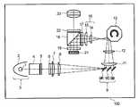
도1은 본 발명의 일 실시예에 따른 디스플레이 장치(100)를 포함하는 광학 유닛의 일반적인 구조를 도시한다. 디스플레이 장치(100)는 본 발명의 일 실시예에 따른 투사식 텔레비전이다.1 shows a general structure of an optical unit including a
도면에 도시된 바와 같이, 반사기(2)를 갖는 램프(아크)(1)로부터의 광을 반사함으로써 얻어지는 램프 유닛(3)으로부터의 광은 S 편광 또는 P 편광으로 광을 변환하도록 편광 비임 스플리터(4)(이하 PBS라 함)를 통과하여 복수개의 제2 램프 화상을 형성하도록 편광이 제1 렌즈 어레이(5)로 들어간다. 다음에, 제1 렌즈 어레이(5)로부터의 광은 복수개의 집광 렌즈를 포함하는 제2 렌즈 어레이(6)를 통과하여 복수개의 제2 램프 화상이 형성되는 영역의 부근에 놓여지고 후술하는 액정 패널(21)(이하 "패널" 또는 "화상 디스플레이 장치"라고 함)의 제1 렌즈 어레이(5)의 각 렌즈의 화상을 형성한다.As shown in the figure, the light from the
제2 렌즈 어레이(6)를 통과한 광은 광을 수렴하는 기능을 하는 제1 렌즈(7) 및 제2 렌즈(8)를 통과하고, 다이크로익 미러 등을 포함하고 백색광을 몇 가지 색상 광선으로 분리하는 [예를 들어, 색상 분리 미러 세트(9)인] 색상 분리기에 도달한다. 렌즈(7, 8)는 이후에 각각 시준 렌즈(7, 8)라고 한다. 색상 분리 미러 세트(9)는 R(적색) 광을 반사하기 위한 R 다이크로익 미러(9R), G(녹색) 광을 반사하기 위한 G 다이크로익 미러(9G) 및 B(청색) 광을 반사하기 위한 B 다이크로익 미러(9B)를 이용한다. R 광을 반사하는 R 다이크로익 미러(9R)는 G 광 및 B 광을 투과시킨다. G 광을 반사하는 G 다이크로익 미러(9G)는 B 광을 투과한다. 광이 R, G, B 광선으로 분리되고 이러한 방식으로 색상 분리 미러 세트(9)에 의해 반사 된 후, R, G, B 광선은 제1 릴레이 렌즈(11)와 제2 릴레이 렌즈(12)를 통과하고 예컨대 8면체와 같은 다면체(13)에 의해 반사되도록 반사식 로터리 다면체(13)의 상이한 영역 상에 지시된다. 반사식 로터리 다면체(13)가 본 실시예에서는 8면체지만, 다면체(13)의 면수는 제한되지 않는다.The light passing through the
R, G, B 광 비임이 다면체(13)의 면들 중 하나에 의해 반사될 때, R, G, B 광 비임의 광축이 한번 교차한다. R, G, B 광 비임 중 두개가 반사식 로터리 다면체(13)의 면들 중 하나에 의해 반사될 때, 이들 비임의 광축은 교차한다. 반사식 로터리 다면체(13)에서 빠져나온 R, G, B 광 비임은 제3 릴레이 렌즈(14) 및 제4 릴레이 렌즈(15) 등으로 구성된 화상 렌즈 시스템(16)을 통과하고 제1 편광판(17)을 통과한다. 그 후에, 분광기로서 PBS(18)에 의해 반사되고 ё/4 파장판(19)을 통과하고 패널(21) 상에 상이한 영역으로 지시된다. 편광 방향이 변화된 패널(21)로부터의 광은 PBS(18)를 통해 이끌리고, 그 다음에 편광판(22)을 통과하고 (도시되지 않은) 스크린 상에 확대되어 투사되도록 최종적으로 투사 렌즈(23)를 통과한다.When the R, G, B light beams are reflected by one of the faces of the
램프 유닛(3)으로부터 색상 분리 미러 세트(9)까지의 부분은 조명 시스템을 구성하고, 제1 릴레이 렌즈로부터 제4 릴레이 렌즈까지의 부분은 본 발명의 일 실시예에 따른 화상 시스템을 구성한다.The portion from the
패널(21)은 투과형 액정 패널(LCD), 반사식 액정 패널(LCOS), 강유전성 액정 패널(FLC) 및 디지털 마이크로-미러 패널일 것이다. 본 발명에서, 이들 패널 중 적합한 것이 사용될 것이다. 본 실시예에서, 패널(21)은 LCOS, LCD 또는 FLC일 것 이다.The
도1에 도시된 실시예에서, 반사식 로터리 다면체(13)의 면들의 수와 크기는 다면체가 회전함에 따라 패널(21) 상의 R, G, B 광선이 주어진 속도로 일방향으로 스크롤하도록 소정의 구성으로 된다.In the embodiment shown in Fig. 1, the number and size of the faces of the
다이크로익 미러(9R, 9G, 9B) 대신에, 다이크로익 프리즘이 광을 R, G, B 광선으로 분리하고 반사 미러 또는 프리즘이 광축 방향으로 제어하는 방식으로 반사 미러 또는 프리즘을 결합한 다이크로익 프리즘이 사용될 수 있다.Instead of
도2를 참조하여, 일정 시간에 로터리 다면체(13)에 의해 디스플레이 장치(21) 상에 반사되는 R, G, B 광선을 지시하는 방법이 이하에 설명된다.Referring to Fig. 2, a method of instructing R, G, and B rays reflected by the
도2는 3가지 색상의 광선이 디스플레이 장치 상에 지시되는 방법을 도시하는 사시도이다. 도2에서, 도면 부호 21R은 R 광선이 지시되는 영역을 나타내고, 21G는 G 광선이 지시되는 영역을 나타내고, 21B는 B 광선이 지시되는 영역을 나타낸다. R, G, B 광선은 동시에 디스플레이 장치(21) 상에 지시된다. 도면부호 25R, 25G, 25B는 R, G, B 광선이 다음에 각각 지시되는 영역을 나타내고, R, G, B 광선이 다음에 지시되는 영역에 어드레스가 기록된다. 이들 영역의 크기는 디스플레이 장치(21)용 기록 시간, 즉 디스플레이 장치(21)의 응답 시간 및 스크롤 속도에 종속된다. 응답 시간이 1행을 스크롤하는데 요구되는 시간보다 짧다면, 이러한 크기는 1행과 동등할 것이다. 한편, 응답이 느리면, 영역에 할당되는 행의 수는 응답 시간에 맞춰진다.Fig. 2 is a perspective view showing how light rays of three colors are directed on the display device. In Fig. 2,
스크롤되는 동안 디스플레이 장치(21) 상의 전술한 것으로부터 처음으로 안 내되는 광선용으로, 색상 코드 어드레스가 위에서 아래의 순서로 색상 영역(21R, 21G, 21B) 상에 기록된다. 한편, 어드레스는 영역(25R, 25G, 25B) 상에 기록된다. 어드레스가 영역(25R, 25G, 25B) 상에 기록된 후에, R, G, B 광선이 영역(25R, 25G, 25B)영역 상에 지시되도록 영역(21R, 21G, 21B) 상에 지시된 R, G, B 광선은 영역(25R, 25G, 25B)과 동일한 양만큼 디스플레이 장치(21) 상에서 하향으로 이동한다. 영역(25R, 25G, 25B) 상에 어드레스가 기록된 후, 어드레스는 그 아래의 다음 행에 기록된다. 이러한 방식으로, R, G, B 광선의 영역은 순차적으로 하향으로 지시된다.For the light rays first guided from the above on the
본 실시예에서, 영역(21R, 21G, 21B)은 실질적으로 동일한 크기여서 제1 렌즈 어레이(5)의 각각의 렌즈의 형상은 (스트립 형상의) R, G, B 광선에 의해 점유되는 디스플레이 장치(21)의 영역(21R, 21G, 21B)의 형상과 유사하다.In the present embodiment, the
스크롤링은 상부로부터 저부로 또는 그 반대로 또는 좌측에서 우측 또는 그 반대로 수행될 수 있다.Scrolling may be performed from top to bottom or vice versa or from left to right or vice versa.
다음에, 본 실시예는 도3 내지 5를 참조하여 상세히 설명된다.Next, this embodiment will be described in detail with reference to Figs.
도3a 및 도3b는 제1 렌즈 어레이 및 제2 렌즈 어레이의 평면도이다. 도1 또는 도3a에 도시된 실시예에서 사용된 제1 렌즈 어레이(5)에서, 렌즈 셀(5a 내지 5x)(이하에서는 종종 제1 렌즈 셀들이라 함)은 장방형이고 도3a에 도시된 바와 같이 파상 패턴(staggered pattern)으로 배열된다. 달리 말하면, 제1 컬럼의 장방형 렌즈 셀(5a 내지 5d)은 수직 방향을 따라 제공된 긴 측면에 정렬되고, 제2 컬럼의 장방형 렌즈 셀(5f 내지 5j)은 수직 방향을 따라 제공된 긴 측면에 또한 정렬된다. 게다가, 제2 컬럼의 렌즈 셀(5f 내지 5j)에 대해, 렌즈 셀의 짧은 측면이 사실상 렌즈 셀(5a 내지 5d)의 긴 측면의 중간 지점에서 이웃 렌즈 셀[즉, 렌즈 셀(5f 및 5g, 5g 및 5h, 5h 및 5i)]의 측면과 접한다. 제3 컬럼은 제1 컬럼과 동일한 방식으로 제2 컬럼에 인접하고, 제4 컬럼은 제2 컬럼과 동일한 방식으로 제3 컬럼에 인접한다. 이하에, 이러한 배열은 파상 패턴이라고 한다. 일 실시예에서, 제1 렌즈 어레이(5)의 렌즈 셀(5a 내지 5x)은 동일한 크기와 치수를 갖는다.3A and 3B are plan views of the first lens array and the second lens array. In the
후술하는 바와 같이, 조명 시스템에서, 제1 렌즈 셀(5a 내지 5x)은 색상 분리 미러 세트(9)의 주변에서 화상을 형성하고, 화상 시스템에서, [색상 분리 미러 세트(9)에 의한 색상 분리의 결과로서] 렌즈 셀(5a 내지 5x)의 단면 형상과 유사한 단면 형상을 갖는 R, G, B 광선은 반사식 로터리 다면체(13)에 의해 반사되고 패널(21) 상에 포커싱된다. 따라서, 제1 렌즈 셀(5a 내지 5x)의 광점과 유사한 형상을 갖는 R, G, B 광점이 패널(21) 상에 나타난다. 따라서, 제1 렌즈 셀(5a 내지 5x)이 다음과 같은 형상을 갖는 것이 바람직하다.As will be described later, in the illumination system, the
색상 광선이 발사되는 방향으로의 패널(21)의 길이(통상 패널의 긴 측면의 길이)는 a로 나타내고, 복수개의 색상의 광선이 발사되는 방향으로의 패널(21)의 길이(짧은 측의 길이)는 b(a>b)로 나타내고, n 색상의 광선이 패널(21) 상에 지시되고, (도3a의) 제1 렌즈 셀(5a 내지 5x)은 긴 측면 대 짧은 측면의 비가 a:(b/n) 이하의 비율이 되도록 형상을 갖는다. 예컨대, 패널(21)의 가로 세로비가 4:3이고 3가지의 광(R, G, B)이 패널(21) 상에 지시되면, 제1 렌즈 셀(5a 내지 5x)의 긴 측면 대 짧은 측면의 비율이 4:3/3 이하인 것이 바람직하고, 어드레싱 폭을 고려하지 않으면 4:1 이하인 것이 바람직하다. 다른 예로써, 패널(21)의 가로 세로비가 16:9이면, 제1 렌즈 셀(5a 내지 5x)의 긴 측면 대 짧은 측면의 비가 16:9/3 이하이거나 또는 16:3이하인 것이 바람직하다. n은 어드레싱 폭(도2의 25R, 25G, 25B)을 고려하여 결정된다. 일 실시예에서, 가로 세로비는 대략 4:1 내지 16:9/4이다.The length of the panel 21 (typically the long side of the panel) in the direction in which the colored light beams are emitted is represented by a, and the length of the
도3b에 도시된 바와 같이, 각각이 대략 정방형인 제2 렌즈 어레이(6)의 렌즈들(이하, 종종 제2 렌즈 셀들이라 함)(6a 내지 6x)을 고려하여, 제1 열의 렌즈 셀들(6a 내지 6c)과 제2 열의 렌즈 셀들(6d 내지 6g)은 도3a에 도시된 제1 및 제2 컬럼의 렌즈 셀들(5a 내지 5j)과 같이 파상 방식으로 배열된다. 일 실시예에서, 제2 렌즈 셀 어레이(6)의 렌즈 셀들(6a 내지 6x)은 동일한 치수와 크기를 갖는다.As shown in Fig. 3B, the
제2 렌즈 셀들은 대략 1:1 내지 1:2의 길이 대 폭 비율을 갖는다. 길이 대 폭 비율은 또한 시선의 각도에 따라 높이 대 폭 비율로서 고려될 수 있다. 제2 렌즈 셀들은 수평으로 정렬된 복수개의 열로 배열된다. 제2 렌즈 어레이(6)는 제1 렌즈 어레이(5)의 장방형 렌즈 셀(5a 내지 5x)의 긴 측면을 따라 길이 방향으로 연장하는 장방형과 같은 전체 형상을 갖는다.The second lens cells have a length to width ratio of approximately 1: 1 to 1: 2. The length to width ratio can also be considered as the height to width ratio depending on the angle of the gaze. The second lens cells are arranged in a plurality of rows arranged horizontally. The
도1을 참조하면, 램프 유닛(3) 내의 램프(아크)(1)의 크기가 제한되기 때문에 반사기(2)로부터 방사된 비임은 평행 요소와 발산 요소를 갖는다. 비임의 평행 요소와 발산 요소는 제1 렌즈 어레이(5) 상에 지시된다. 제2 렌즈 어레이(6)의 렌즈 셀(6a 내지 6x)에 상응하는 제1 렌즈 어레이(5)의 렌즈 셀(5a 내지 5x)용 초점의 주변에, 제1 렌즈 어레이(5)의 렌즈 셀(5a 내지 5x)로부터 방사된 소량의 광선이 제2 렌즈 셀 어레이(6)의 상응하는 렌즈 셀(6a 내지 6x)로 들어가고, 도4a에 도 시된 바와 같이, 다른 광선은 제2 렌즈 어레이(6)의 상응하는 렌즈 셀의 부근에서 렌즈 셀로 들어간다.Referring to Fig. 1, the beam emitted from the
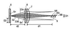
도4a는 광선이 제1 및 제2 렌즈 어레이로부터 색상 분리 미러로 지시되는 방법을 도시한 개략 다이어그램이다.4A is a schematic diagram illustrating how light rays are directed from the first and second lens arrays to the color separation mirror.
도4a를 참조하여, 제1 렌즈 어레이(5)의 렌즈 셀(5n)용으로 렌즈 셀(5n)에 상응하는 [제2 렌즈 어레이(6)의] 렌즈 셀(6n)이 렌즈 셀(5n)용 초점 부근에 위치된다고 가정하면, 렌즈 셀(5n)로부터 방사된 광선의 일부(32)는 렌즈 셀(6n)로 들어가고, 다른 광선(33a, 33b)은 렌즈 셀(6n)에 인접한 렌즈들로 들어간다. 광선(32)은 주요 광으로서 제2 렌즈 어레이(6)로부터 방사되는 반면, 광선(33a, 33b)은 불필요 광으로서 제2 렌즈 어레이(6)로부터 방사된다. 요컨대, 제1 렌즈 어레이(5)의 렌즈 셀(5a 내지 5x)로부터의 광선의 일부는 제2 렌즈 어레이(6)의 상응하는 렌즈 셀(6a 내지 6x)로 들어가고, 다른 광선은 상응하는 렌즈들에 인접한 렌즈 셀로 들어가고, 각각 주요 광 및 불필요 광으로서 제2 렌즈 어레이(6)로부터 빠져나온다. 제2 렌즈 어레이(6)로부터의 주요 광(32)은 조명 시스템[제1 및 제2 시준 렌즈(7, 8) 등]에 의해 집광되어 제1 렌즈 어레이(5)의 렌즈 셀들(5a 내지 5x)로부터의 주요 광이 주요 광 화상으로서 제1 렌즈 셀들과 동일한 형상을 갖는 광의 화상을 형성하도록 다이크로익 미러(9R, 9G, 9B)의 부근에서 서로 모아진다. 그리고, 불필요 광(33a, 33b 등)은 주요 광 화상 부근의 제1 렌즈 셀과 동일한 형상을 갖는 불필요 광 화상을 형성하도록 포커스된다.Referring to Fig. 4A, the
따라서, 불필요 광(33a, 33b)과 주요 광(32)이 모두 R, G, B 광선으로 분리 되고 색상 분리 미러(9)에 의해 반사되면, (R, G, B 다이크로익 미러에 의해 각각 반사된) 불필요 광으로서 R, G, B 광선은 반사식 로터리 다면체(13)의 반사면에서 색상의 혼합 또는 색상 순도 저하를 야기하도록 패널(21) 상에서 서로 혼합되어 지시된다.Thus, if the
이를 방지하기 위해, 본 실시예에서 색상 분리 미러 세트(9)를 구성하는 R 광용 다이크로익 미러(9R), G 광용 다이크로익 미러(9G), B 광용 다이크로익 미러(9B)는 도4a에 도시된 바와 같이 주요 광에 인접한 불필요 광(33a, 33b)이 도달하지 않는 반면, 대부분의 주요 광(32)이 도달하도록 크기가 정해진다.To prevent this, in the present embodiment, the
일 실시예에서, 미러(9R, 9G, 9B)는 도4b에 집합적으로 도시된 바와 같이, 실질적으로 동일한 치수 x, y를 갖는다. 미러의 치수 x, y는 제1 렌즈 어레이(5)의 렌즈 셀들의 치수 X, Y에 각각 상응한다. 도4b는 x:y와 실질적으로 동일한 치수 X, Y를 갖는 제1 렌즈 어레이(5)의 렌즈 셀(50)을 도시한다.In one embodiment, the
도4a를 다시 참조하여, 색상 분리 미러(9R, 9G, 9B)는 높이(또는 길이) y보다 약간 작은 각각의 수직 연장거리 D1를 갖도록 주어진 각도로 경사져 있다. 수직 연장거리는 미러의 상부 에지로부터 하부 에지까지 수직 거리이고, 두 에지는 서로 평행하다. 일 실시예에서, 수직 연장거리 D1은 D1=D2(d1/d2)로 정의되고, 여기서 D2는 렌즈 셀(50)의 수직 거리이고, d2는 제1 렌즈 어레이(5)의 렌즈 셀의 초점거리이고, d1은 제2 렌즈 어레이(6)와 미러(9R, 9G, 9B) 사이에 제공된 렌즈(7)의 초점 거리이다. 다른 실시예에서, 수직 연장거리 D1은 D2(d1/d2)의 90% 내지 110%이거나 또는 D2(d1/d2)의 80% 내지 120%이거나 또는 D2(d1/d2)의 70% 내지 130%이다.Referring again to FIG. 4A, the color separation mirrors 9R, 9G, 9B are inclined at a given angle to have respective vertical extension distances D1 slightly smaller than the height (or length) y. The vertical extension distance is the vertical distance from the top edge to the bottom edge of the mirror and the two edges are parallel to each other. In one embodiment, the vertical extension distance D1 is defined as D1 = D2 (d1 / d2), where D2 is the vertical distance of the
따라서 색상 분리 미러가 수직 연장거리 D1의 크기를 갖도록 제공될 때, 대부분의 불필요 광(33a, 33b)은 제거되거나 또는 반사식 로터리 다면체(13)에 도달하지 못하고, 따라서 패널에 도달하지 못한다. 그 결과, 전술한 문제(색상 혼합 또는 색상 순도 저하)가 방지될 수 있다.Thus, when the color separation mirror is provided to have the size of the vertical extension distance D1, most of the
게다가, 각각의 다이크로익 미러(9R, 9G, 9B)가 주요 광의 덜 강한 부분을 제거하는 구멍으로써 기능할 때, 주요 광의 강도 불균일은 패널(21)에 걸쳐 균일한 광 분포를 갖는 화상을 얻도록 최소화된다.In addition, when each
단면 형상이 제1 렌즈 셀들과 사실상 동일한 다이크로익 미러(9R, 9G, 9B)로부터 반사된 R, G, B 광은 점진적으로 새로운 형상을 취하고, 반사식 로터리 다면체(13)의 부근에서 반사된 후 이들 형상은 전체 제2 렌즈 어레이와 유사하게 되어 제2 렌즈 셀 영역에 상응하는 영역에서 광점을 갖는 광 화상으로 된다. 달리 말하면, 렌즈 셀(5a 내지 5x)로부터의 광은 점진적으로 확장되어 제2 렌즈 어레이(6)를 가로지르는 광점을 갖는 광 화상으로 된다. 제2 렌즈 어레이(6)의 중심의 광점은 크고 강도가 센 반면, 외주 영역에서는 작고 강도가 약하다.R, G, and B light reflected from
색상 분리 미러(9)로부터의 광점은 그 형상이 제1 렌즈 셀의 형상으로부터 전체 제2 렌즈 어레이의 형상으로 변화하는 바와 같이, 반사식 로터리 다면체(13)에 의해 반사된다. 제2 렌즈 어레이와 동일하게 되는 형상을 갖는 광 화상은 광학 화상 시스템(16)을 통과하고 제1 렌즈 셀과 동일한 형상을 갖는 패널(21) 상에 지시됨으로써 다시 새 형상을 취한다. 요약하면, 광 화상의 형상은 색상 분리 미러 의 부근의 제1 렌즈 어레이(제1 렌즈 셀)의 각각의 셀의 형상과 동일하고, 반사식 로터리 다면체(13)의 부근에서 전체 제2 렌즈 어레이의 형상과 동일하고, 다시 패널(21) 상의 각각의 제1 렌즈 셀의 형상과 동일하게 된다.The light spot from the color separation mirror 9 is reflected by the
다음에, 도5a 및 도5b를 참조하여, 도3b에 도시된 하나의 형상과 종래의 광학 유닛에서 종종 볼 수 있는 정방형 또는 원형인 제2 렌즈 어레이의 두 개의 다른 형상이 비교된다.Next, referring to FIGS. 5A and 5B, two different shapes of the second lens array, a square or circular, often seen in conventional optical units, are compared with one shape shown in FIG. 3B.
도5a 및 도5b는 반사식 로터리 다면체의 광점을 도시하는 개략 다이어그램이고, 도5a는 종래의 제2 렌즈 어레이에 의해 생성된 광점을 도시하고 도5b는 본 발명의 일 실시예에 따른 제2 렌즈 어레이에 의한 광점을 도시한다.5A and 5B are schematic diagrams showing light spots of a reflective rotary polyhedron, FIG. 5A shows light spots generated by a conventional second lens array and FIG. 5B is a second lens in accordance with an embodiment of the present invention. The light spot by the array is shown.
제2 렌즈 어레이가 원형이면, 반사식 로터리 다면체(13)의 부근에서의 광점의 형상은 전술한 바와 같이 전체 제2 렌즈 어레이의 형상과 유사하고, 도5a에 도시된 바와 같이, 원형 적색 광점(41R), 녹색 광점(41G), 청색 광점(41B)은 이들 광점(41R, 41G, 41B)을 반사하고 이들을 패널(21) 상으로 배향시키는 반사식 로터리 다면체(13)의 반사면 상에서 지시된다. 이들 각각의 광점이 원형이기 때문에, 적색 광점(41R)의 일부가 녹색 광점(41G)의 일부와 간섭하고 녹색 광점(41G)의 일부가 청색 광점(41B)의 일부와 간섭하여 색상의 혼합과 색상 순도 저하를 야기할 수 있다. 게다가, 간섭 영역, 예컨대 녹색 광점(41G)과 청색 광점(41B) 사이가 반사식 로터리 다면체(13)의 두개의 반사면 사이의 경계가 되면, 광의 일부가 광 손실을 일으키는 산란광으로서 패널(21)의 외측으로 조사된다. 이러한 산란광은 PBS(18), 렌즈(14 또는 15) 또는 편광판(17)의 단부면 등에 의해 반사되어, 패널(21) 또는 투사 렌즈(23)로 안내되어 산란광의 포개짐으로 인한 색상의 혼합이나 콘트래스트 저하를 야기할 수 있다.If the second lens array is circular, the shape of the light spot in the vicinity of the
이와 대조하여, 본 실시예에 따라, 제2 렌즈 어레이(6)는 장방형 제1 렌즈 셀들(5a 내지 5x)의 긴 측면과 평행한 긴 측면을 갖는 장방형이고, 따라서 반사식 로터리 다면체(13)의 반사면 상의 적색 광점(42R), 녹색 광점(42G), 청색 광점(42B)은 전체 제2 렌즈 어레이(6)의 형상과 유사하거나 또는 도5b에 도시된 바와 같이 간섭이 일어나지 않는 장방형이어서, 산란광으로 인한 색상 혼합, 광 손실 또는 콘트래스트 저하가 방지될 수 있다.In contrast, according to the present embodiment, the
본 실시예에서, 제1 렌즈 어레이(5)의 렌즈 셀(5a 내지 5x)은 광선을 확대하고 이를 상응하는 제2 렌즈 어레이(6)의 렌즈 셀(6a 내지6x)로 안내하는 편심 렌즈이다. 이는 제2 렌즈 셀(6a 내지 6x)이 광 손실의 가능성을 감소시키기에 충분히 클 수 있음을 의미한다.In this embodiment, the
선택적으로, 제1 렌즈 셀(5a 내지 5x)[제1 렌즈 어레이(5)의 렌즈 셀]이 반사기의 개구와 유사한 형상이고, 전체 제2 렌즈 어레이는 장방형이고, 제1 렌즈 셀(5a 내지 5x)은 편심 렌즈이고 제2 렌즈 어레이로 지시된 광 비임은 장방형일 때, 도3a 및 3b에 도시된 렌즈 어레이로 얻어지는 효과와 동일한 효과, 예컨대 색상 혼합, 산란광 및 광 손실을 방지하는 것이 달성될 수 있다.Optionally, the
도6은 본 발명의 제2 실시예에 따른 광학 유닛의 사시도이다. 도1에 도시된 것과 동일한 요소들은 동일한 도면 부호로 지시되고 그 설명은 생략된다.6 is a perspective view of an optical unit according to a second embodiment of the present invention. The same elements as those shown in Fig. 1 are designated by the same reference numerals and the description thereof is omitted.
도면에 도시된 바와 같이, 반사기(2)의 외부벽은 장방형 비임이 방사되도록 부분적으로 절결되어 있다. 편광 변환기(61)로 들어간 비임의 일부는 편광 변환기(61)를 통과하고 P 편광으로서 빠져나오고, 다음에 1/2ё파장판에 의해 S 편광으로 변환된 후, 제1 렌즈 어레이(5)로 들어간다. 비임의 다른 부분은 편광 변환기(61)의 제1 반사면(61a)에 의해 반사되고 제2 반사면(61b)에 의해 다시 반사된다. 또한 S 편광으로서 제1 렌즈 어레이(5)로 들어간다. 다음에, 제1 및 제2 시준 렌즈(7, 8)를 통과한 광은 색상 분리 미러(9)에 의해 R, G, B 광선으로 분리되고 광선은 평행 광선으로서 반사식 로터리 다면체(13)로 진행한다. R, G, B 광선이 서로 평행하게 다면체(13)에 충돌함에 따라, 다면체의 반사면 상의 입사각이 동일하고 반사면으로부터 반사된 색상 광선의 광 분포는 R, G, B 광선과 거의 동일하다. 또한, 반사식 로터리 다면체(13)에 의해 반사되고 패널(21) 상으로 지시된 R, G, B 광선은 서로 평행해서 패널(21) 상의 광 이용 효율이 증가된다. 화상 시스템의 렌즈 배율이 증가하면, 수차(aberration)가 발생한다. 그러나, 2 색상의 평행한 광선이 화상 시스템의 렌즈의 단부를 통과함에 따라, 렌즈의 고배율부가 이용될 수 있도록 굴곡될 수 있다. 이는 수차가 화상 시스템에서 저배율 렌즈의 사용에 의해 방지될 수 있음을 의미한다. 반사식 로터리 다면체(13)가 회전함에 따라, 반사된 광선은 평행하지 않게 되지만, R, G, B 광선은 전술한 것과 동일한 효과를 달성할 수 있도록 동일한 방식으로 변경된다.As shown in the figure, the outer wall of the
본 실시예에서, 제1 렌즈 어레이(5)의 렌즈 셀(5a 내지 5x)은 광선을 확대하고 이를 제2 렌즈 어레이(6)의 상응하는 렌즈 셀(6a 내지 6x)로 안내하는 편심 렌즈이기 때문에, 제2 렌즈 셀(6a 내지 6x)은 광 손실의 가능성을 감소시키기에 충분히 클 수 있다. 이러한 경우, 제1 렌즈 셀(5a 내지 5x)은 PBS(61)와 유사한 형상인 것이 바람직하다.In this embodiment, since the
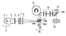
도7은 본 발명의 제3 실시예에 따른 광학 유닛의 사시도이다. 도1에 도시된 것과 동일한 요소는 동일한 도면 부호로 지시되고 그 설명은 생략된다. 도면 부호 79는 색상 분리 미러를 지시한다. 색상 분리 미러(79)는 다음과 같이 준비된다. 유리판들 사이와 외측 유리판의 외측면에 다이크로익 미러를 갖는 3매의 유리판으로 구성된 유리판 조립체가 입사광 측이 광선에 대략 직각인 방식으로 스트립으로 절결되고, 그 다음에 연마된다.7 is a perspective view of an optical unit according to a third embodiment of the present invention. The same elements as shown in Fig. 1 are designated by the same reference numerals and the description thereof is omitted.
R 광용 다이크로익 미러(9R), G 광용 다이크로익 미러(9G), B 광용 다이크로익 미러(9B)가 공기 중에 제공되는 도1에 도시된 경우와 비교하여, 유리와 다이크로익 미러로 제조된 본 실시예의 색상 분리 미러(79)는 미러들 사이의 물리적인 거리가 동일하지만, 광학 길이는 상이하다. 도1에 도시된 바와 같이 도면 부호 c가 미러들(9R 및 9G) 사이와 미러들(9G, 9B) 사이의 거리를 나타내고, d가 본 실시예에 따른 색상 분리 미러(79)의 미러들(79R, 79G) 사이와 미러들(79G, 79B) 사이의 거리를 나타내고, n이 유리의 굴절률을 나타낸다고 가정한다. 물리적인 거리에서 c=d이더라도, 유리 색상 분리 미러(79)의 광학 길이는 c/n(f=c/n)으로 표현되므로 더 짧다. 따라서, 색상 분리 미러[79; R 광용 미러(79R), G 광용 미러(79G), B 광용 미러(79B)]에 의해 불필요한 광을 제거하기 쉽다. 한편, 색상 분리 미러(79)의 광학 길이가 짧을 수 있기 때문에, 초점이 흐려짐에 의한 패널의 R, G, B 광점이 흐려지는 것이 감소될 수 있다. 또한, 불필요 광이 색상 분리 미러(79)의 짧은 광학 길이에 의해 제거될 수 있다. 주요 광 분포의 강도 불균일을 방지하고 패널(21)에 걸쳐 일정한 광 분포를 갖는 화상을 얻기 위해 주요 광의 강도가 낮은 부분을 제거하도록 색상 분리 미러(79)가 주요 광이 새 형상을 취하기 위한 구멍으로서의 기능을 가질 수 있다.Glass and dichroic mirrors as compared to the case shown in FIG. 1 in which an R light
렌즈 어레이(71)는 각각의 렌즈가 볼록 렌즈의 특정 폭을 갖는 중심부로 구성된 3매의 렌즈들의 조합이다. 이러한 렌즈 어레이(71)는 집광하거나 발산하여 반사식 로터리 다면체(13)의 반사면의 광점이 포커싱된다. 더 상세히는, 광점의 크기가 더 작은 패널 상에 광점을 만들어서 색상 광선이 혼합되는 것을 방지하도록 세 개의 광(R, G, B)들 사이의 간격이 증가될 수 있다. 작은 광점은 데이터를 기록하는 데 충분한 시간을 얻는 것이 가능하도록 패널 상의 가드 밴드 부식을 방지할 수 있다.The
렌즈 어레이(71)에 의한 집광은 화상 렌즈에 의한 수차를 방지할 수 있어서 화상 시스템에서 두꺼운 렌즈를 사용할 필요가 없게 한다.Condensing by the
본 실시예에서, 색상 분리 미러(79)로부터의 광선이 서로 평행하고 또한 반사식 로터리 다면체(13)로부터의 광선이 서로 평행하고, 색상 분리 미러(79)로부터 패널(21)로의 R, G, B 광선의 광학 경로의 길이가 사실상 같아서, 패널의 R, G, B 광점의 크기가 거의 동일하다. 이러한 이유로, 우수한 색상 밸런스가 보장되고 휘도의 감퇴가 방지될 수 있다. 게다가, 색상 분리 미러(79)와 반사식 로터리 다면체(13)부터 방사된 광선이 평행하다는 사실은 다른 장점을 제공하고, 도6을 참조하여 설명된 바와 같은 동일한 효과가 얻어질 수 있다.In this embodiment, the light rays from the
유리 색상 분리 미러(79)는 작은 다이크로익 프리즘이고, 도8에 도시된 바와 같이 구성될 수 있다.The glass
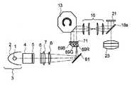
도8은 본 발명의 제4 실시예에 다른 광학 유닛(화상 장치)의 일반적인 구조를 도시한다. 도면에서 유리 분리 미러(89)로 도시된 바와 같이, 조명 시스템의 제2 렌즈 어레이로부터의 광이 도시된 바와 같이 아래쪽으로부터 색상 반사 미러(89)로 들어가고 R 광선이 투과하고 G 및 B 광선이 반사되도록 배열이 이루어 질 수 있다. 이러한 경우, 반사식 로터리 다면체(13)의 R, G, B 광점은 유사한 크기이고, 광 경로 차이로 인한 크기 차가 제거될 수 있다. 또한, 도8에 도시된 바와 같이, 광 경로는 구조적 무결성이 요구될 때 반사 미러(81)들에 의해 굴곡될 수 있다.Fig. 8 shows a general structure of an optical unit (imaging apparatus) according to the fourth embodiment of the present invention. As shown by the glass separating mirror 89 in the figure, the light from the second lens array of the illumination system enters the color reflecting mirror 89 from below, as shown, the R light beam is transmitted and the G and B light beams are reflected. The arrangement can be made as much as possible. In this case, the R, G, B light spots of the
본 실시예에서, 분광기로서 편평한 PBS(18a)가 이용된다. 이는 도1에 도시된 바와 같이 프리즘 PBS(18)와 동일한 효과를 제공한다.In this embodiment, a
도9는 본 발명의 제5 실시예에 따른 광학 유닛의 일반적인 구조를 도시한다. 도1에 도시된 것과 동일한 요소는 동일한 도면 부호로 나타내고 그 설명은 생략된다. 도면 부호 91은 R 광용 색상 분리 미러(91R), G 광용 색상 분리 미러(91G), B 광용 색상 분리 미러(91B)를 포함하는 색상 분리 조립체를 나타낸다. 색상 분리 미러(91R, 91G, 91B)로부터 방사된 광선은 사실상 서로 평행하고 포커싱 광의 기능을 갖는 제1 및 제2 렌즈(11a, 12a)에 의해 반사식 로터리 다면체(13) 상에 포커싱된다. 렌즈(11a, 12a)는 또한 시준 렌즈라고도 한다. 반사식 로터리 다면체(13)에 의해 반사된 R, G, B 광선은 서로의 경로와 교차하고, 사실상 서로 평행한 집광 렌즈(92)로 들어가고, 사실상 서로 평행하게 빠져나오고, 다음에 PBS(18)로 들어간다.9 shows a general structure of an optical unit according to the fifth embodiment of the present invention. The same elements as those shown in Fig. 1 are designated by the same reference numerals and the description thereof is omitted.
제2 렌즈 어레이(6)와 색상 분리 미러 조립체(91) 사이에는 시준 렌즈와 같은 렌즈가 없고, 반사식 로터리 다면체(13)로부터 반사된 R, G, B 광은 어떤 화상 렌즈도 이용하지 않고 집광 렌즈(92)에 의해 거의 평행하게 된다.There is no lens, such as a collimating lens, between the
제2 렌즈 조립체(6)가 도3b에 도시된 바와 같이 구성될 때, 반사식 로터리 다면체(13)의 R, G, B 색상 광점은 겹쳐지지 않아서 화상 시스템은 더 이상 필요없다. 본 실시예에서, 불필요광은 색상 분리 미러(91)에 의해 발생된다. 대책으로서, 필요하다면 불필요 광이 반사식 로터리 다면체(13)에 도달하는 것을 방지하기 위해, 색상 분리 미러(91)로부터 반사식 로터리 다면체(13)까지의 R, G, B 광 경로 내에 구멍이 설치될 수 있다. 제1 렌즈 어레이(5)와 제2 렌즈 어레이(6) 사이의 거리가 짧고, 제2 렌즈 어레이(6)로부터 방사된 주요 광과 불필요 광 사이의 각도가 크고, 주요 광과 불필요 광 사이의 거리가 길 때, 색상 분리 미러(91)는 이를 고려하여 설계될 수 있다.When the
도10은 본 발명의 제6 실시예에 따른 광학 유닛의 분해도이다. 도10에서, 도1에 도시된 요소에 상응하는 요소는 동일한 도면 부호로 나타내고 그 설명은 생략된다.10 is an exploded view of an optical unit according to the sixth embodiment of the present invention. In Fig. 10, elements corresponding to those shown in Fig. 1 are designated by the same reference numerals and description thereof is omitted.
도1에 도시된 제1 렌즈 어레이(5)에 대해, 각각의 렌즈 셀의 짧은 측은 도1을 참조하여 설명된 바와 같이 제1 렌즈 어레이의 용이한 조립을 위해 충분히 짧게 되어야 한다. 이러한 문제에 대한 해결책은 근측 대 원측의 비율이 가능한 한 1( 즉, 정방형)에 근접하고 색상 분리 미러에 의해 원하는 비율로 그 비율을 변화시키는 제1 렌즈 셀을 사용하는 것이다. 본 실시예는 제1 렌즈 어레이의 제조를 손쉽게 하기 위해 이러한 접근을 채용할 수 있다.For the
도10에 도시된 바와 같이, 제1 렌즈 어레이(5a)의 렌즈 셀은 색상 분리 미러에 요구되는 제1 렌즈 셀 화상보다 정방형에 근접한 형태이다. 일 실시예에서, 제1 렌즈 셀의 길이 대 폭의 비는 1:1에서 3:16까지이다. 제2 렌즈 어레이(6a)의 각각의 렌즈 셀은 도1에 도시된 바와 같이 정방형과 유사하다. 본 실시예에서, 제1 및 제2 렌즈 어레이(5a, 6a)의 렌즈 셀들은 파상 패턴으로 배열되지 않았지만, 그렇게 배열될 수 있다.As shown in Fig. 10, the lens cells of the
도10을 참조하면, 제1 및 제2 렌즈 어레이(5a, 6a)로부터 방사된 광선은 분광기로서의 PBS(4)에 의해 S 편광 또는 P 편광으로 변환되어 원통형 렌즈(101), 제1 시준 렌즈(7) 및 제2 시준 렌즈(8)를 통과하여 색상 분리 미러(도시되지 않음)에 도달한다. 도면 부호(102)는 예컨대 G광용 색상 분리 미러 상에 형성된 광점이다.Referring to FIG. 10, light rays emitted from the first and
도10에서, 제1 렌즈 어레이(5a)의 각각의 렌즈 셀의 긴 측면과 짧은 측면은 각각 도면 부호 A1 및 A2로 나타내고, 제1 렌즈 어레이(5a)와 제2 렌즈 어레이(6a) 사이의 거리는 도면 부호 a로 나타낸다. 제1 렌즈 셀의 짧은 측 방향으로 원통형 렌즈와 시준 렌즈들의 합성 초점 거리는 도면 부호 b1로 나타내고, 제1 렌즈 셀의 긴 측 방향으로의 합성 초점 거리는 도면 부호 b2로 나타낸다. 상응하는 광점(102)의 긴 측의 길이는 도면 부호 B1로 나타내고, 광점(102)의 짧은 측의 길 이는 도면 부호 B2로 나타낸다. 여기서, 확대도 M1 (=B1/A1) = b2/a 이고, 확대도 M2 (=B2/A2) = b1/a 의 관계를 만족한다. 따라서, M1 > M2, 즉 b2 > b1의 관계를 만족할 때, 광점의 짧은 측 대 긴 측의 비율은 제1 렌즈 셀의 짧은 측 대 긴 측의 비율보다 작다.In Fig. 10, the long side and the short side of each lens cell of the
본 실시예에서, 긴측에 대한 색상 분리 미러의 광점의 짧은 측의 길이의 비율은 이러한 방식으로 감소될 수 있어서, 제1 렌즈 어레이의 각각의 렌즈 셀의 짧은 측이 요구하는 것보다 길게 할 수 있다. 이는 제1 렌즈 어레이(5a)의 제조를 손쉽게 한다.In this embodiment, the ratio of the length of the short side of the light spot of the color separation mirror to the long side can be reduced in this way, so that the short side of each lens cell of the first lens array can be longer than required. . This makes it easy to manufacture the
제1 렌즈 어레이의 각각의 렌즈 셀의 형상은 도1의 실시예보다 정방형에 더 근접하기 때문에, 광 손실을 감소시킨다. 광점(102)의 짧은 측은 불필요광의 발생 가능성을 최소화하도록 짧아진다.Since the shape of each lens cell of the first lens array is closer to the square than the embodiment of Fig. 1, it reduces the light loss. The short side of the
전술한 실시예에서, 중심축 주위에 링 형상으로 배열된 로터리 다면체의 복수개의 반사면은 편평하고 직선의 평면이다. 그러나, 본 발명은 이에 제한되지 않는다. 반사면은 굴곡될 수 있다. 반사면이 굴곡되면, 디스플레이 장치의 R, G, B 광선의 스크롤 속도를 거의 일정하게 제어하는 것이 가능하다.In the above-described embodiment, the plurality of reflective surfaces of the rotary polyhedron arranged in a ring shape around the central axis are flat and straight planes. However, the present invention is not limited to this. The reflective surface can be curved. When the reflecting surface is bent, it is possible to control the scroll speed of the R, G, and B light beams of the display device to be substantially constant.
전술한 바와 같이, 본 실시예에 따라, 패널 상의 복수개의 색상의 광점의 혼합과 콘트래스트 저하의 발생이 줄어든다. 게다가, 광활용 효율이 개선될 수 있다.As described above, according to the present embodiment, the mixing of the light spots of the plurality of colors on the panel and the occurrence of contrast degradation are reduced. In addition, the light utilization efficiency can be improved.
전술한 설명은 양호한 실시예에 대해 설명하였다. 그러나, 당해 기술 분야의 숙련자에 의해 이들 실시예의 다양한 변경이 존재한다는 것이 이해될 것이다. 이러한 변경은 본 발명의 범주와 첨부된 특허청구의 범위 내에서 제한된다.The foregoing description has described a preferred embodiment. However, it will be understood by those skilled in the art that various changes in these embodiments exist. Such changes are limited within the scope of the invention and the scope of the appended claims.
전술한 상세한 설명은 본 발명의 특정 실시예를 설명하기 위해 제공되었고, 이에 제한되지 않는다. 본 발명의 범주 내에서 다양한 변형 및 변경이 가능하다. 따라서, 본 발명은 첨부된 특허청구의 범위에 의해 한정된다.The foregoing detailed description has been provided to describe particular embodiments of the present invention, but is not limited to such. Many modifications and variations are possible within the scope of the invention. Accordingly, the invention is defined by the appended claims.
본 발명에 따라, 패널 상에 지시된 광선의 색상 혼합 가능성과 화상 콘트래스트 저하를 최소화하고 광 이용 효율을 개선하는 신규하고 유용한 화상 디스플레이 기술이 제공된다.In accordance with the present invention, there is provided a novel and useful image display technique which minimizes the color mixing possibilities of the light beam directed on the panel and the image contrast degradation and improves the light utilization efficiency.
Claims (20)
Translated fromKoreanApplications Claiming Priority (2)
| Application Number | Priority Date | Filing Date | Title |
|---|---|---|---|
| JP2002056868AJP2003255250A (en) | 2002-03-04 | 2002-03-04 | Optical unit and image display device using the same |
| JPJP-P-2002-00056868 | 2002-03-04 |
Publications (2)
| Publication Number | Publication Date |
|---|---|
| KR20030072224A KR20030072224A (en) | 2003-09-13 |
| KR100549136B1true KR100549136B1 (en) | 2006-02-03 |
Family
ID=27764430
Family Applications (1)
| Application Number | Title | Priority Date | Filing Date |
|---|---|---|---|
| KR1020030010236AExpired - Fee RelatedKR100549136B1 (en) | 2002-03-04 | 2003-02-19 | Projection type image display apparatus |
Country Status (6)
| Country | Link |
|---|---|
| US (1) | US7170567B2 (en) |
| EP (1) | EP1345454A2 (en) |
| JP (1) | JP2003255250A (en) |
| KR (1) | KR100549136B1 (en) |
| CN (1) | CN1258106C (en) |
| TW (1) | TW591943B (en) |
Families Citing this family (18)
| Publication number | Priority date | Publication date | Assignee | Title |
|---|---|---|---|---|
| JP2003262808A (en)* | 2002-03-07 | 2003-09-19 | Hitachi Ltd | Optical unit and image display device using the same |
| JP4089572B2 (en) | 2003-09-24 | 2008-05-28 | セイコーエプソン株式会社 | Lighting device, image display device, and projector |
| JP2005164824A (en)* | 2003-12-01 | 2005-06-23 | Seiko Epson Corp | projector |
| JP2005189847A (en)* | 2003-12-03 | 2005-07-14 | Seiko Epson Corp | projector |
| US7274500B2 (en)* | 2003-12-03 | 2007-09-25 | Eastman Kodak Company | Display system incorporating trilinear electromechanical grating device |
| US7404643B2 (en)* | 2004-07-12 | 2008-07-29 | Seiko Epson Corporation | Projector having polarization conversion element |
| JP2007025308A (en)* | 2005-07-19 | 2007-02-01 | Hitachi Ltd | Projection-type image display device and color separation unit |
| JP2007226172A (en)* | 2006-01-30 | 2007-09-06 | Sony Corp | Image projection apparatus |
| US7883216B2 (en)* | 2006-02-13 | 2011-02-08 | High Definition Integration Ltd. | Methods and systems for multiple primary color display |
| JP4832187B2 (en)* | 2006-07-03 | 2011-12-07 | 富士フイルム株式会社 | High-speed polarizing device, high-speed birefringence measuring device using the same, and stereoscopic image display device |
| CN101377572A (en)* | 2007-08-28 | 2009-03-04 | 鸿富锦精密工业(深圳)有限公司 | Stereo projection optical system |
| CN102053464B (en)* | 2009-10-27 | 2012-08-08 | 台达电子工业股份有限公司 | Lens array group and projector |
| EP2693239B1 (en)* | 2011-02-28 | 2016-10-12 | Pioneer Corporation | Optical element, headup display, and method for manufacturing optical element |
| US10606161B2 (en)* | 2016-07-19 | 2020-03-31 | Maxell, Ltd. | Projection video display apparatus |
| US10983317B2 (en)* | 2017-07-04 | 2021-04-20 | Suzhou Ned+Ar Tcoe Techonolgy Co., Ltd. | Compact, lightweight optical imaging system having free-form surface and common optical axis direction |
| CN111856862B (en)* | 2019-04-30 | 2023-05-02 | 深圳光峰科技股份有限公司 | Light source system and display equipment |
| CN112449096B (en)* | 2020-12-04 | 2025-08-19 | 无锡灵汐类脑科技有限公司 | Lens array, sensor array and lighting device |
| US11674655B2 (en)* | 2021-07-14 | 2023-06-13 | Edgar Madril | System and method for high efficiency forward lighting collimating projection system |
Family Cites Families (7)
| Publication number | Priority date | Publication date | Assignee | Title |
|---|---|---|---|---|
| US5410370A (en) | 1990-12-27 | 1995-04-25 | North American Philips Corporation | Single panel color projection video display improved scanning |
| JP2000098296A (en)* | 1998-09-17 | 2000-04-07 | Sharp Corp | Projection type color image display device |
| EP1070984A1 (en) | 1999-02-04 | 2001-01-24 | Matsushita Electric Industrial Co., Ltd. | Projector and display both comprising optical element for diffraction and scattering |
| JP4053212B2 (en) | 2000-04-05 | 2008-02-27 | 松下電器産業株式会社 | Color image display device |
| US6511184B2 (en) | 2000-04-05 | 2003-01-28 | Matsushita Electric Industrial Co., Ltd. | Color image display apparatus |
| JP4061857B2 (en)* | 2001-04-27 | 2008-03-19 | 株式会社日立製作所 | Optical unit and video display device using the same |
| US6860607B2 (en)* | 2002-03-15 | 2005-03-01 | Seiko Epson Corporation | Integrator type illumination optical system and projector having the same |
- 2002
- 2002-03-04JPJP2002056868Apatent/JP2003255250A/ennot_activeWithdrawn
- 2003
- 2003-01-15EPEP03000878Apatent/EP1345454A2/ennot_activeWithdrawn
- 2003-01-30TWTW092102297Apatent/TW591943B/ennot_activeIP Right Cessation
- 2003-02-19KRKR1020030010236Apatent/KR100549136B1/ennot_activeExpired - Fee Related
- 2003-02-20CNCNB031054137Apatent/CN1258106C/ennot_activeExpired - Fee Related
- 2003-03-03USUS10/379,312patent/US7170567B2/ennot_activeExpired - Fee Related
Also Published As
| Publication number | Publication date |
|---|---|
| US20030164901A1 (en) | 2003-09-04 |
| EP1345454A2 (en) | 2003-09-17 |
| CN1258106C (en) | 2006-05-31 |
| US7170567B2 (en) | 2007-01-30 |
| TW591943B (en) | 2004-06-11 |
| CN1442722A (en) | 2003-09-17 |
| KR20030072224A (en) | 2003-09-13 |
| TW200305335A (en) | 2003-10-16 |
| JP2003255250A (en) | 2003-09-10 |
Similar Documents
| Publication | Publication Date | Title |
|---|---|---|
| KR100549136B1 (en) | Projection type image display apparatus | |
| US6343862B1 (en) | Projecting image display device | |
| JP3635867B2 (en) | Projection type liquid crystal display device | |
| KR100569793B1 (en) | Projection type liquid crystal display device | |
| KR100930237B1 (en) | Illumination optical system employing a dichroic mirror wheel and an image display device having the same | |
| JP2001051231A (en) | Display optical device | |
| JP2008197664A (en) | Display device | |
| JP2000180796A (en) | Projection type image display device | |
| US7198376B2 (en) | Illumination optical unit liquid crystal projector and production method of liquid crystal projector | |
| US6860607B2 (en) | Integrator type illumination optical system and projector having the same | |
| KR20000075786A (en) | Multi-color-band light source | |
| KR100597820B1 (en) | Display device with optical device and optical device | |
| US6219112B1 (en) | Illumination optical system and liquid crystal projector apparatus using the same | |
| JP2000241768A (en) | Illumination optical device | |
| US6457828B1 (en) | Display optical apparatus | |
| JPH08129138A (en) | Projection type image display device | |
| JP2001091894A (en) | Display optical device | |
| WO2001077737A1 (en) | Color image display apparatus | |
| JP2006215536A (en) | Optical system for projection display, and projector incorporating it | |
| JP3413099B2 (en) | Lighting device for LCD projector | |
| JPH0822006A (en) | Liquid crystal projector | |
| JPH11295658A (en) | Liquid crystal projector | |
| JP4174931B2 (en) | Lighting device and projection display device | |
| JP3963415B2 (en) | Display optical device | |
| JPH10111486A (en) | Display device, liquid crystal panel for display device, and projection display device |
Legal Events
| Date | Code | Title | Description |
|---|---|---|---|
| A201 | Request for examination | ||
| PA0109 | Patent application | St.27 status event code:A-0-1-A10-A12-nap-PA0109 | |
| PA0201 | Request for examination | St.27 status event code:A-1-2-D10-D11-exm-PA0201 | |
| PG1501 | Laying open of application | St.27 status event code:A-1-1-Q10-Q12-nap-PG1501 | |
| PN2301 | Change of applicant | St.27 status event code:A-3-3-R10-R13-asn-PN2301 St.27 status event code:A-3-3-R10-R11-asn-PN2301 | |
| R18-X000 | Changes to party contact information recorded | St.27 status event code:A-3-3-R10-R18-oth-X000 | |
| D13-X000 | Search requested | St.27 status event code:A-1-2-D10-D13-srh-X000 | |
| D14-X000 | Search report completed | St.27 status event code:A-1-2-D10-D14-srh-X000 | |
| E902 | Notification of reason for refusal | ||
| PE0902 | Notice of grounds for rejection | St.27 status event code:A-1-2-D10-D21-exm-PE0902 | |
| T11-X000 | Administrative time limit extension requested | St.27 status event code:U-3-3-T10-T11-oth-X000 | |
| T11-X000 | Administrative time limit extension requested | St.27 status event code:U-3-3-T10-T11-oth-X000 | |
| E13-X000 | Pre-grant limitation requested | St.27 status event code:A-2-3-E10-E13-lim-X000 | |
| P11-X000 | Amendment of application requested | St.27 status event code:A-2-2-P10-P11-nap-X000 | |
| P13-X000 | Application amended | St.27 status event code:A-2-2-P10-P13-nap-X000 | |
| E701 | Decision to grant or registration of patent right | ||
| PE0701 | Decision of registration | St.27 status event code:A-1-2-D10-D22-exm-PE0701 | |
| GRNT | Written decision to grant | ||
| PR0701 | Registration of establishment | St.27 status event code:A-2-4-F10-F11-exm-PR0701 | |
| PR1002 | Payment of registration fee | St.27 status event code:A-2-2-U10-U11-oth-PR1002 Fee payment year number:1 | |
| PG1601 | Publication of registration | St.27 status event code:A-4-4-Q10-Q13-nap-PG1601 | |
| LAPS | Lapse due to unpaid annual fee | ||
| PC1903 | Unpaid annual fee | St.27 status event code:A-4-4-U10-U13-oth-PC1903 Not in force date:20090127 Payment event data comment text:Termination Category : DEFAULT_OF_REGISTRATION_FEE | |
| PC1903 | Unpaid annual fee | St.27 status event code:N-4-6-H10-H13-oth-PC1903 Ip right cessation event data comment text:Termination Category : DEFAULT_OF_REGISTRATION_FEE Not in force date:20090127 |