KR100547755B1 - Optical fiber manufacturing apparatus and method using spin - Google Patents
Optical fiber manufacturing apparatus and method using spinDownload PDFInfo
- Publication number
- KR100547755B1 KR100547755B1KR1020030033197AKR20030033197AKR100547755B1KR 100547755 B1KR100547755 B1KR 100547755B1KR 1020030033197 AKR1020030033197 AKR 1020030033197AKR 20030033197 AKR20030033197 AKR 20030033197AKR 100547755 B1KR100547755 B1KR 100547755B1
- Authority
- KR
- South Korea
- Prior art keywords
- optical fiber
- spin
- wheel
- axis
- coating
- Prior art date
- Legal status (The legal status is an assumption and is not a legal conclusion. Google has not performed a legal analysis and makes no representation as to the accuracy of the status listed.)
- Expired - Fee Related
Links
Images


Classifications
- G—PHYSICS
- G02—OPTICS
- G02B—OPTICAL ELEMENTS, SYSTEMS OR APPARATUS
- G02B6/00—Light guides; Structural details of arrangements comprising light guides and other optical elements, e.g. couplings
- G02B6/04—Light guides; Structural details of arrangements comprising light guides and other optical elements, e.g. couplings formed by bundles of fibres
- C—CHEMISTRY; METALLURGY
- C03—GLASS; MINERAL OR SLAG WOOL
- C03B—MANUFACTURE, SHAPING, OR SUPPLEMENTARY PROCESSES
- C03B37/00—Manufacture or treatment of flakes, fibres, or filaments from softened glass, minerals, or slags
- C03B37/01—Manufacture of glass fibres or filaments
- C03B37/02—Manufacture of glass fibres or filaments by drawing or extruding, e.g. direct drawing of molten glass from nozzles; Cooling fins therefor
- C03B37/03—Drawing means, e.g. drawing drums ; Traction or tensioning devices
- C03B37/032—Drawing means, e.g. drawing drums ; Traction or tensioning devices for glass optical fibres
- C—CHEMISTRY; METALLURGY
- C03—GLASS; MINERAL OR SLAG WOOL
- C03B—MANUFACTURE, SHAPING, OR SUPPLEMENTARY PROCESSES
- C03B37/00—Manufacture or treatment of flakes, fibres, or filaments from softened glass, minerals, or slags
- C03B37/01—Manufacture of glass fibres or filaments
- C03B37/02—Manufacture of glass fibres or filaments by drawing or extruding, e.g. direct drawing of molten glass from nozzles; Cooling fins therefor
- C03B37/025—Manufacture of glass fibres or filaments by drawing or extruding, e.g. direct drawing of molten glass from nozzles; Cooling fins therefor from reheated softened tubes, rods, fibres or filaments, e.g. drawing fibres from preforms
- C03B37/027—Fibres composed of different sorts of glass, e.g. glass optical fibres
- C03B37/02745—Fibres having rotational spin around the central longitudinal axis, e.g. alternating +/- spin to reduce polarisation mode dispersion
- C—CHEMISTRY; METALLURGY
- C03—GLASS; MINERAL OR SLAG WOOL
- C03B—MANUFACTURE, SHAPING, OR SUPPLEMENTARY PROCESSES
- C03B2203/00—Fibre product details, e.g. structure, shape
- C03B2203/10—Internal structure or shape details
- C03B2203/18—Axial perturbations, e.g. in refractive index or composition
- C03B2203/19—Alternating positive/negative spins or twists
- C—CHEMISTRY; METALLURGY
- C03—GLASS; MINERAL OR SLAG WOOL
- C03B—MANUFACTURE, SHAPING, OR SUPPLEMENTARY PROCESSES
- C03B2203/00—Fibre product details, e.g. structure, shape
- C03B2203/36—Dispersion modified fibres, e.g. wavelength or polarisation shifted, flattened or compensating fibres (DSF, DFF, DCF)
Landscapes
- Chemical & Material Sciences (AREA)
- Engineering & Computer Science (AREA)
- Manufacturing & Machinery (AREA)
- Life Sciences & Earth Sciences (AREA)
- General Life Sciences & Earth Sciences (AREA)
- Geochemistry & Mineralogy (AREA)
- Materials Engineering (AREA)
- Organic Chemistry (AREA)
- Dispersion Chemistry (AREA)
- Physics & Mathematics (AREA)
- General Physics & Mathematics (AREA)
- Optics & Photonics (AREA)
- Surface Treatment Of Glass Fibres Or Filaments (AREA)
- Manufacture, Treatment Of Glass Fibers (AREA)
Abstract
Translated fromKoreanDescription
Translated fromKorean도 1은 본 발명의 바람직한 실시예에 따른 스핀을 이용한 광섬유 제조 장치의 구성을 나타내는 도면,1 is a view showing the configuration of an optical fiber manufacturing apparatus using spin according to a preferred embodiment of the present invention;
도 2a 내지 도 2b는 도 1에 도시된 제1 및 제2 휠의 제1 작동예를 나타내는 도면,2a to 2b show a first example of operation of the first and second wheels shown in FIG.
도 3a 내지 도 3b는 도 1에 도시된 제1 및 제2 휠의 제2 작동예를 나타내는 도면,3A to 3B show a second example of operation of the first and second wheels shown in FIG. 1,
도 4a 내지 도 4b는 도 1에 도시된 제1 및 제2 휠의 제3 작동예를 나타내는 도면.4A-4B show a third example of operation of the first and second wheels shown in FIG. 1;
본 발명은 광섬유에 관한 것으로서, 특히 광섬유 제조 장치 및 방법에 관한 것이다.TECHNICAL FIELD The present invention relates to optical fibers, and more particularly, to an optical fiber manufacturing apparatus and method.
편광 모드 분산(Polariztion Mode Dispersion: PMD)는 광섬유의 물리적 성질과 광섬유를 통과하는 빛의 편광 상태 사이의 상호작용에 의해 발생하는 것으로, 코어(core) 비원률 및 굴절률 비대칭, 인출 공정에서의 스트레스(stress) 비대칭 등에 의해 나타나는 복굴절에 의해 두 편광 축들을 따라 진행하는 편광 성분들의 속도들(group velocity)이 차이를 보이게 되고, 이 결과 도착 시간의 차이(differential group delay; DGD)에 의한 펄스(pulse) 퍼짐이 발생하는 것을 말한다. 이러한 PMD 현상을 제어하기 위하여 여러 가지 방법이 이용되는데 일반적으로 광섬유에 스핀(spin)을 인가하고, 모드 커플링(mode-coupling)을 통해 DGD를 줄이는 것이 효과적이라고 알려져 있다. 광섬유 내에서 편광 모드가 위치하는 주축들(principle axes)은 일정한 방향성 없이 무작위적으로 위치한다. 따라서 광 펄스(pulse)가 진행할 경우 에너지 교환에 의한 커플링(coupling)이 일어나게 되는데, 이러한 모드 커플링 결과로서 광섬유 내에 존재하는 두 모드들의 속도차가 줄게 되어 빛이 통과하는 광섬유 길이가 길어질수록 PMD가 낮아진다. 그러나 주축들이 무작위적으로 위치하기 때문에 PMD의 통계적인 경향성만을 확인할 수 있으며, 개개의 PMD 측정 결과는 입사 편광 및 측정 조건에 따라 큰 편차를 가진다. 광섬유를 인출 공정에서 인위적으로 꼬아주면, 편광 모드가 위치하는 주축들이 이동하게 되는데, 일정한 주기로 광섬유를 꼬아서 무작위로 배치되어 있는 주축들에 방향성을 부여한다. 즉, 어느 한 주축 상의 느린 모드(slow mode)와 나머지 주축 상의 빠른 모드(fast mode)가 번갈아 가면서 일정한 주기로 배열되도록 한다. 이렇게 꼬인 광섬유는 국부적으로는 편광에 의한 분산이 일어나지만 일정 길이 이상에서는 PMD 가 감소하게 된다. 대니 엘. 헨더슨(Dany L. Henderson) 등에 의해 발명되어 특허허여된 미국특허번호 제5,943,466호(FREQUENCY AND AMPLITUDE MODULATED FIBER SPINS FOR PMD REDUCTION)에서는 진폭과 주기를 사인 펑션 등에 의하여 모듈레이션한 사인 함수 형태의 스핀 펑션에 대하여 개시하고 있다.Polarization Mode Dispersion (PMD) is caused by the interaction between the physical properties of an optical fiber and the polarization state of light passing through the optical fiber. The birefringence caused by the asymmetry of stress causes the difference in the group velocity of the polarization components traveling along the two polarization axes, resulting in a pulse due to the differential group delay (DGD). Spread occurs. Various methods are used to control the PMD phenomenon. Generally, it is known that spin is applied to an optical fiber and reduction of DGD through mode-coupling is effective. Principal axes in which the polarization mode is located in the optical fiber are randomly located without constant direction. Therefore, when the light pulse proceeds, coupling occurs due to energy exchange. As a result of this mode coupling, the speed difference between the two modes existing in the optical fiber decreases, so that the PMD becomes longer as the optical fiber passes through the light. Lowers. However, because the principal axes are randomly located, only the statistical tendency of the PMD can be confirmed, and the individual PMD measurement results have a large deviation depending on incident polarization and measurement conditions. When the optical fiber is twisted artificially in the extraction process, the main axes in which the polarization mode is located move. The optical fibers are twisted at regular intervals to give direction to the randomly arranged main axes. That is, a slow mode on one main axis and a fast mode on the other main axis are alternately arranged at regular intervals. The twisted fiber is locally dispersed by polarized light, but PMD decreases over a certain length. Danny L. U.S. Patent No. 5,943,466 (FREQUENCY AND AMPLITUDE MODULATED FIBER SPINS FOR PMD REDUCTION), invented and patented by Dany L. Henderson, et al. It is starting.
상술한 바와 같은 종래의 스핀을 이용한 광섬유 제조 방법은 통상적으로 코터(coater)를 통과한 후 피복이 경화된 광섬유에 스핀을 인가함으로써, 용융로(furnace) 내부에 장착된 광섬유 모재의 끝단에 이러한 스핀이 전달되도록 한다. 이 때, 상기 광섬유를 잡아서 당기는 장치(통상적으로 캡스턴(capstan)이라고 칭함)와 상기 코터 사이에 스핀 장치가 배치된다. 상기 광섬유 모재의 끝단은 상기 용융로에 의해 용융 상태에 있게 되며, 상기 광섬유 모재로부터 인출되어 냉각된 광섬유는 꼬임 상태를 유지하게 되며, 이후 코팅된 광섬유의 피복도 꼬임 상태를 유지하게 된다(이하, "피복 꼬임"이라고 칭함). 이러한 방식은 스핀을 인가할 때 발생하는 측방향 응력(shear stress)에 의하여 광섬유가 단선되는 것을 방지할 수 있으나, 상기 캡스턴 이후의 광섬유 부분도 이러한 스핀에 영향을 받게 된다는 문제점이 있다. 다시 말해서, 상기 캡스턴을 지난 광섬유는 피복 꼬임을 유지한 채로 광섬유 스풀에 귄취되는데, 이후 상기 광섬유를 루즈 튜브(loose tube) 등에 케이블링(cabling)할 때 이러한 피복 꼬임이 상기 광섬유의 국부 스트레스 분포 등에 원하지 않았던 영향을 끼치게 된다는 문제점이 있다.In the conventional optical fiber manufacturing method using the spin as described above, such a spin is applied to the end of the optical fiber base material mounted inside the furnace by applying a spin to the optically cured fiber after passing through a coater. To be delivered. At this time, a spin device is disposed between the device for catching and pulling the optical fiber (commonly referred to as capstan) and the coater. The ends of the optical fiber base material are in a molten state by the melting furnace, and the optical fiber drawn out of the optical fiber base material and cooled is kept in a twisted state, and then the coating of the coated optical fiber is also held in a twisted state (hereinafter referred to as "coating "Twist"). This method can prevent the optical fiber from being disconnected due to the lateral stress generated when applying the spin, but the optical fiber portion after the capstan is also affected by the spin. In other words, the optical fiber passing through the capstan is held in the optical fiber spool while maintaining the fiber twist, and when the fiber is then cabled to a loose tube or the like, the fiber twist is applied to the local stress distribution of the optical fiber. The problem is that it has an unwanted effect.
본 발명은 상술한 종래의 문제점을 해결하기 위하여 안출한 것으로서, 본 발명의 목적은 PMD를 제거하기 위해 광섬유에 스핀을 인가하면서도 피복 꼬임을 배제할 수 있는 스핀을 이용한 광섬유 제조 방법 및 장치를 제공함에 있다. The present invention has been made to solve the above-mentioned conventional problems, an object of the present invention to provide a method and apparatus for manufacturing an optical fiber using a spin that can eliminate the coating twist while applying a spin to the optical fiber to remove the PMD. have.
상기한 문제점을 해결하기 위하여, 본 발명에 따른 스핀을 이용한 광섬유 제조 방법은, 광섬유 모재의 끝단을 용융시켜서 광섬유를 인출하는 단계와; 상기 광섬유에 피복을 코팅하는 단계와; 상기 광섬유에 일 방향으로 스핀을 인가하는 단계와; 상기 광섬유에 타 방향으로 스핀을 인가함으로써 상기 광섬유 피복의 꼬임 상태를 해소하는 단계를 포함한다.In order to solve the above problems, the optical fiber manufacturing method using a spin according to the present invention comprises the steps of: melting the end of the optical fiber base material to take out the optical fiber; Coating a coating on the optical fiber; Applying spin to the optical fiber in one direction; Removing the twisted state of the fiber coating by applying spin to the optical fiber in the other direction.
또한, 본 발명에 따른 스핀을 이용한 광섬유 제조 장치는, 광섬유 모재의 끝단을 용융시켜서 광섬유를 인출하기 위한 용융로와; 상기 광섬유와 접하며 그 제1 축 주위로 회전하는 외주면을 갖고, 상기 광섬유에 일방향의 스핀을 인가하는 제1 휠과; 상기 광섬유와 접하며 그 제2 축 주위로 회전하는 외주면을 갖고, 상기 광섬유에 타방향의 스핀을 인가하는 제2 휠을 포함한다.
In addition, the optical fiber manufacturing apparatus using the spin according to the present invention, the melting furnace for pulling out the optical fiber by melting the end of the optical fiber base material; A first wheel having an outer circumferential surface in contact with the optical fiber and rotating about a first axis thereof, the first wheel applying spin in one direction to the optical fiber; And a second wheel having an outer circumferential surface in contact with the optical fiber and rotating about its second axis, and applying spin in the other direction to the optical fiber.
이하에서는 첨부도면들을 참조하여 본 발명의 실시예를 상세히 설명하기로 한다. 본 발명을 설명함에 있어서, 관련된 공지기능이나 구성에 대한 구체적인 설명은 본 발명의 요지를 모호하지 않게 하기 위하여 생략한다.Hereinafter, with reference to the accompanying drawings will be described an embodiment of the present invention; In describing the present invention, detailed descriptions of related well-known functions and configurations are omitted in order not to obscure the subject matter of the present invention.
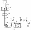
도 1은 본 발명의 바람직한 실시예에 따른 스핀을 이용한 광섬유 제조 장치의 구성을 나타내는 도면이다. 상기 제조 장치는 용융로(110), 코터(140), 캡스턴(150), 제1 및 제2 휠(wheel, 160,170) 및 다수의 도르래(181~184)를 포함한다.1 is a view showing the configuration of an optical fiber manufacturing apparatus using spin according to a preferred embodiment of the present invention. The manufacturing apparatus includes a
상기 용융로(110)는 실린더(cylinder) 형태를 가지며, 내부에 삽입된 광섬유 모재(optical fiber preform, 120)의 끝단을 가열하여 용융시킨다. 상기 광섬유 모재는 그로부터 인출되는 광섬유(130)와 동일한 구성을 가지나, 그 직경이 상기 광섬유(130)에 비해 매우 크다. 또한, 상기 용융로(110) 내부가 열에 의해 산화되는 것을 방지하기 위하여, 상기 용융로(110) 내부에 불활성 기체를 흐르게 할 수 있다.The
상기 코터(140)는 상기 용융로(110)에서 인출되는 광섬유(130)에 자외선 경화성 수지, 열경화성 수지 등의 코팅액을 도포함으로써, 상기 광섬유(130)에 피복을 코팅한다. 상기 코팅액으로서 자외선 경화성 수지를 사용하는 경우에는 상기 코터(140)의 하단에 상기 자외선 경화수지에 자외선을 조사하여 경화시키는 자외선 경화기를 추가적으로 구비해야 한다.The
상기 캡스턴(150)은 상기 광섬유(130)를 기설정된 힘으로 잡아 당겨서, 상기 광섬유 모재(120)로부터 상기 광섬유(130)가 일정 직경을 유지하면서 연속적으로 인출될 수 있도록 한다.The
상기 제1 휠(160)은 상기 코터(140)와 상기 캡스턴(150) 사이에 배치되며, 회전축에 해당하는 제1 축과 상기 광섬유(130)와 접하며 상기 제1 축 주위로 회전하는 외주면을 갖는다. 상기 제1 축은 광섬유 인출축과 수직을 이루는 위치를 기준으로 기설정된 각도 범위 내에서 진동하거나 기설정된 각도로 기울어져 있음으로 써, 상기 광섬유(130)가 상기 제1 휠(160)의 외주면을 따라 구르도록 한다. 즉, 상기 제1 휠(160)은 상기 광섬유(130)에 스핀을 인가하고, 이러한 스핀은 상기 광섬유 모재(120)의 끝단에 전달된다.The
상기 제2 휠(170)은 상기 광섬유 인출 경로를 따라 상기 캡스턴(150) 이후에 배치되며, 제2축과 상기 광섬유(130)와 접하며 상기 제2 축 주위로 회전하는 외주면을 갖는다. 상기 제2 축은 상기 광섬유 인출축과 수직을 이루는 위치를 기준으로 기설정된 각도 범위 내에서 진동하거나 기설정된 각도로 기울어져 있음으로써, 상기 광섬유(130)가 상기 제2 휠(170)의 외주면을 따라 구르도록 한다. 상기 제1 및 제2 휠(160,170)은 서로 반대 방향으로 진동하거나 기울어져 있다. 상기 제2 휠(170)은 상기 광섬유(130)에 스핀을 인가함으로써, 상기 제1 휠(160)에 의한 상기 광섬유(130) 피복의 꼬임 상태를 해소한다. 즉, 상기 제1 휠(160)에 의해 야기된 상기 광섬유(130) 피복의 꼬임 상태는 상기 캡스턴(150) 이전의 광섬유 인출 구간 뿐만 아니라, 그 이후의 광섬유 인출 구간에서도 유지된다. 상기 제2 휠(170)은 상기 캡스턴(150) 이후의 광섬유 인출 구간에 배치되며, 상기 광섬유(130)에 타방향의 스핀을 인가함으로써 해당 구간 내에서 상기 제1 휠(160)에 의해 야기된 상기 광섬유(130) 피복의 꼬임 상태를 해소하게 된다.The
상기 다수의 도르래(181~184)는 상기 광섬유 인출 경로 상에 설치됨으로써 그 경로 변경을 돕는 기능을 한다.The plurality of
상술한 실시예에서, 제1 및 제2 휠(160,170) 사이에 위치하는 캡스턴(150)은 상기 제2 휠(170)이 상기 제1 휠(160)의 역방향으로 위치하여 광섬유(130) 피복의 꼬임 상태를 해소할 수 있도록 상기 광섬유(130)를 잡아주는 역할을 한다. 만약, 상기 캡스턴(150)과 같이 상기 제1 및 제2 휠(160,170) 사이에 상기 광섬유(130)를 잡아주는 기능을 하는 장치가 없다면, 상기 광섬유(130)에 꼬임을 주는 것은 불가능하다. 상기 캡스턴(150) 이외에 상기 제1 및 제2 휠(160,170) 사이에 상기 광섬유(130)를 잡아주는 장치가 위치하는 경우에 상기 캡스턴(150)은 상기 제2 휠 이후의 광섬유 인출 구간에 배치될 수도 있다. 예를 들어, 인출 공정 상의 안정성을 고려할 때 바람직하지 않을 수 있으나, 상기 제1 및 제2 휠(160,170) 사이에 상기 광섬유(130)를 잡아주는 추가의 도르래를 설치할 수도 있다. 이러한 경우에, 상기 제2 휠(170)은 상기 추가 도르래 및 캡스턴(150) 사이에 배치되며, 상기 광섬유(130)에 스핀을 인가함으로써 상기 광섬유(130) 피복의 꼬임 상태를 해소한다.In the above-described embodiment, the
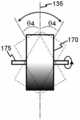
도 2a 내지 도 2b는 도 1에 도시된 제1 및 제2 휠의 제1 작동예를 나타내는 도면이다. 상기 제1 휠(160)은 회전축에 해당하는 제1 축(165)이 광섬유 인출축(135)을 기준으로 시계방향의 θ1의 범위 내에서 진동한다. 상기 제2 휠(170)은 회전축에 해당하는 제2 축(175)이 광섬유 인출축(135)을 기준으로 반시계방향의 θ2의 범위 내에서 진동한다. 상기 제1 및 제2 휠(160,170)은 서로 반대 방향으로 진동한다.2A to 2B are views showing a first operation example of the first and second wheels shown in FIG. 1. The
도 3a 내지 도 3b는 도 1에 도시된 제1 및 제2 휠의 제2 작동예를 나타내는 도면이다. 상기 제1 휠(160)은 회전축에 해당하는 제1 축(165)이 광섬유 인출축(135)을 기준으로 좌우로 각각 θ3의 범위 내에서 진동한다. 상기 제2 휠(170)은 회전축에 해당하는 제2 축(175)이 광섬유 인출축(135)을 기준으로 좌우로 각각 θ4의 범위 내에서 진동한다. 상기 제1 및 제2 휠(160,170)은 서로 반대 방향으로 진동한다.3A to 3B are views showing a second example of operation of the first and second wheels shown in FIG. The
도 4a 내지 도 4b는 도 1에 도시된 제1 및 제2 휠의 제3 작동예를 나타내는 도면이다. 상기 제1 휠(160)은 회전축에 해당하는 제1 축(165)이 광섬유 인출축(135)을 기준으로 시계방향의 θ5만큼 기울어져 있다. 상기 제2 휠(170)은 회전축에 해당하는 제2 축(175)이 광섬유 인출축(135)을 기준으로 반시계방향의 θ6만큼 기울어져 있다. 상기 제1 및 제2 휠(160,170)은 서로 반대 방향으로 기울어져 있다.4A to 4B are views showing a third operation example of the first and second wheels shown in FIG. 1. The
상술한 바와 같이, 본 발명에 따른 스핀을 이용한 광섬유 제조 방법 및 장치는 서로 반대 방향으로 진동하거나 기울어져 있는 제1 및 제2 휠을 이용함으로써 PMD를 제거하면서도 피복 꼬임을 배제할 수 있다는 이점이 있다.
As described above, the optical fiber manufacturing method and apparatus using the spin according to the present invention has the advantage that it is possible to eliminate the coating twist while removing the PMD by using the first and second wheels oscillating or tilting in opposite directions. .
Claims (8)
Translated fromKoreanPriority Applications (5)
| Application Number | Priority Date | Filing Date | Title |
|---|---|---|---|
| KR1020030033197AKR100547755B1 (en) | 2003-05-24 | 2003-05-24 | Optical fiber manufacturing apparatus and method using spin |
| US10/778,562US20040231366A1 (en) | 2003-05-24 | 2004-02-13 | Apparatus and method for fabricating optical fiber by spinning |
| CNB2004100284495ACN100357205C (en) | 2003-05-24 | 2004-03-11 | Apparatus and method for fabricating optical fiber by spinning |
| EP20040008106EP1481951A1 (en) | 2003-05-24 | 2004-04-02 | Apparatus and method for fabricating optical fiber by spinning |
| JP2004152356AJP4009274B2 (en) | 2003-05-24 | 2004-05-21 | Optical fiber manufacturing apparatus and method using spin |
Applications Claiming Priority (1)
| Application Number | Priority Date | Filing Date | Title |
|---|---|---|---|
| KR1020030033197AKR100547755B1 (en) | 2003-05-24 | 2003-05-24 | Optical fiber manufacturing apparatus and method using spin |
Publications (2)
| Publication Number | Publication Date |
|---|---|
| KR20040100747A KR20040100747A (en) | 2004-12-02 |
| KR100547755B1true KR100547755B1 (en) | 2006-01-31 |
Family
ID=33129036
Family Applications (1)
| Application Number | Title | Priority Date | Filing Date |
|---|---|---|---|
| KR1020030033197AExpired - Fee RelatedKR100547755B1 (en) | 2003-05-24 | 2003-05-24 | Optical fiber manufacturing apparatus and method using spin |
Country Status (5)
| Country | Link |
|---|---|
| US (1) | US20040231366A1 (en) |
| EP (1) | EP1481951A1 (en) |
| JP (1) | JP4009274B2 (en) |
| KR (1) | KR100547755B1 (en) |
| CN (1) | CN100357205C (en) |
Families Citing this family (9)
| Publication number | Priority date | Publication date | Assignee | Title |
|---|---|---|---|---|
| JP2006327413A (en)* | 2005-05-26 | 2006-12-07 | Takata Corp | Seat belt retractor, seat belt device, and vehicle equipped with seat belt device |
| JP4495029B2 (en)* | 2005-05-13 | 2010-06-30 | 古河電気工業株式会社 | Method for manufacturing coated optical fiber |
| KR100808354B1 (en)* | 2006-08-17 | 2008-02-27 | 엘에스전선 주식회사 | Single mode optical fiber with reduced polarization mode dispersion and manufacturing method thereof |
| JP4851368B2 (en)* | 2007-03-05 | 2012-01-11 | 古河電気工業株式会社 | Optical fiber manufacturing method |
| DE102007022272B4 (en)* | 2007-05-09 | 2016-06-02 | Heraeus Quarzglas Gmbh & Co. Kg | A method of manufacturing a quartz glass tube by elongating a quartz glass hollow cylinder |
| JP5229319B2 (en) | 2008-06-05 | 2013-07-03 | 住友電気工業株式会社 | Coated optical fiber manufacturing apparatus and coated optical fiber manufacturing method |
| CN102267800B (en)* | 2010-06-07 | 2013-09-11 | 苏州光环科技有限公司 | Optical fiber twisting recovering method and device |
| JP5948136B2 (en)* | 2011-05-27 | 2016-07-06 | 株式会社フジクラ | Optical fiber and manufacturing method thereof |
| CN115650576A (en)* | 2022-11-03 | 2023-01-31 | 中天科技光纤有限公司 | Method for preparing prefabricated rod, method and equipment for preparing optical fiber and optical fiber |
Family Cites Families (8)
| Publication number | Priority date | Publication date | Assignee | Title |
|---|---|---|---|---|
| US5298047A (en)* | 1992-08-03 | 1994-03-29 | At&T Bell Laboratories | Method of making a fiber having low polarization mode dispersion due to a permanent spin |
| DE19504521C2 (en)* | 1995-02-11 | 2000-11-09 | Felten & Guilleaume Ag | Process for the production of an optical fiber |
| US5704960A (en)* | 1995-12-20 | 1998-01-06 | Corning, Inc. | Method of forming an optical fiber for reduced polarization effects in amplifiers |
| WO1997030945A1 (en)* | 1996-02-26 | 1997-08-28 | Corning Incorporated | Method and apparatus for providing controlled spin in optical fiber |
| WO2000044680A1 (en)* | 1999-01-27 | 2000-08-03 | Sumitomo Electric Industries, Ltd. | Method and device for producing covered optical fiber and covered optical fiber |
| JP2002226229A (en)* | 2000-11-29 | 2002-08-14 | Furukawa Electric Co Ltd:The | Optical fiber continuous twisting device |
| WO2004050573A1 (en)* | 2002-09-25 | 2004-06-17 | Giacomo Stefano Roba | Process for producing an optical fiber having a low polarization mode dispersion |
| AU2002361253B2 (en)* | 2002-12-30 | 2009-11-05 | Prysmian Cavi E Sistemi Energia S.R.L. | Method for producing an optical fiber having low polarization mode dispersion |
- 2003
- 2003-05-24KRKR1020030033197Apatent/KR100547755B1/ennot_activeExpired - Fee Related
- 2004
- 2004-02-13USUS10/778,562patent/US20040231366A1/ennot_activeAbandoned
- 2004-03-11CNCNB2004100284495Apatent/CN100357205C/ennot_activeExpired - Fee Related
- 2004-04-02EPEP20040008106patent/EP1481951A1/ennot_activeWithdrawn
- 2004-05-21JPJP2004152356Apatent/JP4009274B2/ennot_activeExpired - Fee Related
Also Published As
| Publication number | Publication date |
|---|---|
| EP1481951A1 (en) | 2004-12-01 |
| JP2004345947A (en) | 2004-12-09 |
| CN1572743A (en) | 2005-02-02 |
| KR20040100747A (en) | 2004-12-02 |
| JP4009274B2 (en) | 2007-11-14 |
| US20040231366A1 (en) | 2004-11-25 |
| CN100357205C (en) | 2007-12-26 |
Similar Documents
| Publication | Publication Date | Title |
|---|---|---|
| KR100328205B1 (en) | Fiber Optic Manufacturing Method | |
| EP1325894B1 (en) | Multimode optical fibers with increased bandwith | |
| US7317855B2 (en) | Method of imparting twist to optical fiber | |
| US6859596B2 (en) | Systems and methods for forming ultra-low PMD optical fiber using amplitude and frequency keyed fiber spin functions | |
| EP1532475B1 (en) | Apparatus for applying spin to optical fiber and optical fiber manufacturing method and apparatus using the same | |
| KR100547755B1 (en) | Optical fiber manufacturing apparatus and method using spin | |
| JP4768605B2 (en) | Method of manufacturing a rotating optical fiber having low polarization mode dispersion | |
| CN100437169C (en) | Low Polarization Mode Dispersion (PMD) optical fiber link and method of making same | |
| US6945079B2 (en) | Optical fiber drawing system for non-contact control of polarization mode dispersion of optical fiber | |
| KR100566218B1 (en) | Apparatus and method for optical fiber extraction | |
| CN101341101A (en) | Method and apparatus for producing optical fibers with reduced polarization mode dispersion | |
| JP2001302272A (en) | Optical fiber manufacturing method and apparatus | |
| JPH10203849A (en) | Apparatus for producing optical fiber and production of the optical fiber | |
| WO2004078665A1 (en) | Method and apparatus for impulse spinning of an optical fiber during drawing | |
| KR100642378B1 (en) | Device for improving polarization mode dispersion using pressure change around optical fiber and optical fiber manufacturing device using the same | |
| KR19990061841A (en) | Fiber optic extractor | |
| JP2004099350A (en) | Optical fiber manufacturing apparatus and manufacturing method |
Legal Events
| Date | Code | Title | Description |
|---|---|---|---|
| A201 | Request for examination | ||
| PA0109 | Patent application | St.27 status event code:A-0-1-A10-A12-nap-PA0109 | |
| PA0201 | Request for examination | St.27 status event code:A-1-2-D10-D11-exm-PA0201 | |
| R18-X000 | Changes to party contact information recorded | St.27 status event code:A-3-3-R10-R18-oth-X000 | |
| D13-X000 | Search requested | St.27 status event code:A-1-2-D10-D13-srh-X000 | |
| D14-X000 | Search report completed | St.27 status event code:A-1-2-D10-D14-srh-X000 | |
| PG1501 | Laying open of application | St.27 status event code:A-1-1-Q10-Q12-nap-PG1501 | |
| E902 | Notification of reason for refusal | ||
| PE0902 | Notice of grounds for rejection | St.27 status event code:A-1-2-D10-D21-exm-PE0902 | |
| P11-X000 | Amendment of application requested | St.27 status event code:A-2-2-P10-P11-nap-X000 | |
| P13-X000 | Application amended | St.27 status event code:A-2-2-P10-P13-nap-X000 | |
| E902 | Notification of reason for refusal | ||
| PE0902 | Notice of grounds for rejection | St.27 status event code:A-1-2-D10-D21-exm-PE0902 | |
| PN2301 | Change of applicant | St.27 status event code:A-3-3-R10-R13-asn-PN2301 St.27 status event code:A-3-3-R10-R11-asn-PN2301 | |
| PN2301 | Change of applicant | St.27 status event code:A-3-3-R10-R13-asn-PN2301 St.27 status event code:A-3-3-R10-R11-asn-PN2301 | |
| E701 | Decision to grant or registration of patent right | ||
| PE0701 | Decision of registration | St.27 status event code:A-1-2-D10-D22-exm-PE0701 | |
| GRNT | Written decision to grant | ||
| PR0701 | Registration of establishment | St.27 status event code:A-2-4-F10-F11-exm-PR0701 | |
| PR1002 | Payment of registration fee | St.27 status event code:A-2-2-U10-U11-oth-PR1002 Fee payment year number:1 | |
| PG1601 | Publication of registration | St.27 status event code:A-4-4-Q10-Q13-nap-PG1601 | |
| LAPS | Lapse due to unpaid annual fee | ||
| PC1903 | Unpaid annual fee | St.27 status event code:A-4-4-U10-U13-oth-PC1903 Not in force date:20090124 Payment event data comment text:Termination Category : DEFAULT_OF_REGISTRATION_FEE | |
| PC1903 | Unpaid annual fee | St.27 status event code:N-4-6-H10-H13-oth-PC1903 Ip right cessation event data comment text:Termination Category : DEFAULT_OF_REGISTRATION_FEE Not in force date:20090124 | |
| R18-X000 | Changes to party contact information recorded | St.27 status event code:A-5-5-R10-R18-oth-X000 |