KR100547566B1 - PET Bottle Production Automation Line - Google Patents
PET Bottle Production Automation LineDownload PDFInfo
- Publication number
- KR100547566B1 KR100547566B1KR1020030080784AKR20030080784AKR100547566B1KR 100547566 B1KR100547566 B1KR 100547566B1KR 1020030080784 AKR1020030080784 AKR 1020030080784AKR 20030080784 AKR20030080784 AKR 20030080784AKR 100547566 B1KR100547566 B1KR 100547566B1
- Authority
- KR
- South Korea
- Prior art keywords
- preform
- pet bottle
- unit
- feeder
- pet
- Prior art date
- Legal status (The legal status is an assumption and is not a legal conclusion. Google has not performed a legal analysis and makes no representation as to the accuracy of the status listed.)
- Expired - Fee Related
Links
Images


Classifications
- B—PERFORMING OPERATIONS; TRANSPORTING
- B29—WORKING OF PLASTICS; WORKING OF SUBSTANCES IN A PLASTIC STATE IN GENERAL
- B29C—SHAPING OR JOINING OF PLASTICS; SHAPING OF MATERIAL IN A PLASTIC STATE, NOT OTHERWISE PROVIDED FOR; AFTER-TREATMENT OF THE SHAPED PRODUCTS, e.g. REPAIRING
- B29C49/00—Blow-moulding, i.e. blowing a preform or parison to a desired shape within a mould; Apparatus therefor
- B29C49/42—Component parts, details or accessories; Auxiliary operations
- B29C49/4205—Handling means, e.g. transfer, loading or discharging means
- B—PERFORMING OPERATIONS; TRANSPORTING
- B29—WORKING OF PLASTICS; WORKING OF SUBSTANCES IN A PLASTIC STATE IN GENERAL
- B29C—SHAPING OR JOINING OF PLASTICS; SHAPING OF MATERIAL IN A PLASTIC STATE, NOT OTHERWISE PROVIDED FOR; AFTER-TREATMENT OF THE SHAPED PRODUCTS, e.g. REPAIRING
- B29C49/00—Blow-moulding, i.e. blowing a preform or parison to a desired shape within a mould; Apparatus therefor
- B29C49/02—Combined blow-moulding and manufacture of the preform or the parison
- B29C49/06—Injection blow-moulding
- B29C49/061—Injection blow-moulding with parison holding means displaceable between injection and blow stations
- B—PERFORMING OPERATIONS; TRANSPORTING
- B29—WORKING OF PLASTICS; WORKING OF SUBSTANCES IN A PLASTIC STATE IN GENERAL
- B29C—SHAPING OR JOINING OF PLASTICS; SHAPING OF MATERIAL IN A PLASTIC STATE, NOT OTHERWISE PROVIDED FOR; AFTER-TREATMENT OF THE SHAPED PRODUCTS, e.g. REPAIRING
- B29C49/00—Blow-moulding, i.e. blowing a preform or parison to a desired shape within a mould; Apparatus therefor
- B29C49/08—Biaxial stretching during blow-moulding
- B29C49/16—Biaxial stretching during blow-moulding using pressure difference for pre-stretching, e.g. pre-blowing
- B—PERFORMING OPERATIONS; TRANSPORTING
- B29—WORKING OF PLASTICS; WORKING OF SUBSTANCES IN A PLASTIC STATE IN GENERAL
- B29C—SHAPING OR JOINING OF PLASTICS; SHAPING OF MATERIAL IN A PLASTIC STATE, NOT OTHERWISE PROVIDED FOR; AFTER-TREATMENT OF THE SHAPED PRODUCTS, e.g. REPAIRING
- B29C49/00—Blow-moulding, i.e. blowing a preform or parison to a desired shape within a mould; Apparatus therefor
- B29C49/28—Blow-moulding apparatus
- B29C49/30—Blow-moulding apparatus having movable moulds or mould parts
- B—PERFORMING OPERATIONS; TRANSPORTING
- B29—WORKING OF PLASTICS; WORKING OF SUBSTANCES IN A PLASTIC STATE IN GENERAL
- B29C—SHAPING OR JOINING OF PLASTICS; SHAPING OF MATERIAL IN A PLASTIC STATE, NOT OTHERWISE PROVIDED FOR; AFTER-TREATMENT OF THE SHAPED PRODUCTS, e.g. REPAIRING
- B29C49/00—Blow-moulding, i.e. blowing a preform or parison to a desired shape within a mould; Apparatus therefor
- B29C49/42—Component parts, details or accessories; Auxiliary operations
- B29C49/64—Heating or cooling preforms, parisons or blown articles
- B29C49/6409—Thermal conditioning of preforms
- B29C49/6418—Heating of preforms
- B—PERFORMING OPERATIONS; TRANSPORTING
- B29—WORKING OF PLASTICS; WORKING OF SUBSTANCES IN A PLASTIC STATE IN GENERAL
- B29C—SHAPING OR JOINING OF PLASTICS; SHAPING OF MATERIAL IN A PLASTIC STATE, NOT OTHERWISE PROVIDED FOR; AFTER-TREATMENT OF THE SHAPED PRODUCTS, e.g. REPAIRING
- B29C49/00—Blow-moulding, i.e. blowing a preform or parison to a desired shape within a mould; Apparatus therefor
- B29C49/42—Component parts, details or accessories; Auxiliary operations
- B29C49/70—Removing or ejecting blown articles from the mould
- B—PERFORMING OPERATIONS; TRANSPORTING
- B29—WORKING OF PLASTICS; WORKING OF SUBSTANCES IN A PLASTIC STATE IN GENERAL
- B29C—SHAPING OR JOINING OF PLASTICS; SHAPING OF MATERIAL IN A PLASTIC STATE, NOT OTHERWISE PROVIDED FOR; AFTER-TREATMENT OF THE SHAPED PRODUCTS, e.g. REPAIRING
- B29C49/00—Blow-moulding, i.e. blowing a preform or parison to a desired shape within a mould; Apparatus therefor
- B29C49/02—Combined blow-moulding and manufacture of the preform or the parison
- B29C2049/023—Combined blow-moulding and manufacture of the preform or the parison using inherent heat of the preform, i.e. 1 step blow moulding
- B—PERFORMING OPERATIONS; TRANSPORTING
- B29—WORKING OF PLASTICS; WORKING OF SUBSTANCES IN A PLASTIC STATE IN GENERAL
- B29C—SHAPING OR JOINING OF PLASTICS; SHAPING OF MATERIAL IN A PLASTIC STATE, NOT OTHERWISE PROVIDED FOR; AFTER-TREATMENT OF THE SHAPED PRODUCTS, e.g. REPAIRING
- B29C49/00—Blow-moulding, i.e. blowing a preform or parison to a desired shape within a mould; Apparatus therefor
- B29C49/42—Component parts, details or accessories; Auxiliary operations
- B29C49/70—Removing or ejecting blown articles from the mould
- B29C2049/701—Ejecting means
- B—PERFORMING OPERATIONS; TRANSPORTING
- B29—WORKING OF PLASTICS; WORKING OF SUBSTANCES IN A PLASTIC STATE IN GENERAL
- B29K—INDEXING SCHEME ASSOCIATED WITH SUBCLASSES B29B, B29C OR B29D, RELATING TO MOULDING MATERIALS OR TO MATERIALS FOR MOULDS, REINFORCEMENTS, FILLERS OR PREFORMED PARTS, e.g. INSERTS
- B29K2067/00—Use of polyesters or derivatives thereof, as moulding material
- B29K2067/003—PET, i.e. poylethylene terephthalate
- B—PERFORMING OPERATIONS; TRANSPORTING
- B29—WORKING OF PLASTICS; WORKING OF SUBSTANCES IN A PLASTIC STATE IN GENERAL
- B29L—INDEXING SCHEME ASSOCIATED WITH SUBCLASS B29C, RELATING TO PARTICULAR ARTICLES
- B29L2031/00—Other particular articles
- B29L2031/712—Containers; Packaging elements or accessories, Packages
- B29L2031/7158—Bottles
Landscapes
- Engineering & Computer Science (AREA)
- Manufacturing & Machinery (AREA)
- Mechanical Engineering (AREA)
- Physics & Mathematics (AREA)
- Thermal Sciences (AREA)
- Blow-Moulding Or Thermoforming Of Plastics Or The Like (AREA)
Abstract
Translated fromKoreanDescription
Translated fromKorean도 1은 본 발명에 따른 페트병 생산 자동화 라인의 전체 도면도.
도 2는 본 발명에 따른 자동화 라인의 엘리베이터 피더부 구조도.
도 3은 본 발명에 따른 자동화 라인의 프리폼스토퍼와 셔틀피더부 구조도.
도 4는 본 발명에 따른 자동화 라인의 1차 프리폼 반전 장치부 구조도.
도 5는 본 발명에 따른 자동화 라인의 프리폼 히팅존부 구조도.
도 6은 본 발명에 따른 자동화 라인의 2차 프리폼 반전 장치부 구조도.
도 7은 본 발명에 따른 자동화 라인의 3차 프리폼 이송장치부 구조도.
도 8은 본 발명에 따른 자동화 라인의 피치이송 구동부 구조도.
도 9는 본 발명에 따른 자동화 라인의 프리폼 운송장치부 구조도.
도 10은 본 발명에 따른 자동화 라인의 페트병 브로잉 금형장치부 구조도.
도 11은 본 발명에 따른 자동화 라인의 페트병 브로잉 늘림장치부 구조도.
도 12는 본 발명에 따른 자동화 라인의 페트병 취출장치부 구조도.
〈도면의 주요 부분에 대한 부호의 설명〉
① : 엘리베이터 피더. ② : 셔틀 피더.
③ : 프리폼 반전장치(1차). ④ : 프리폼 히팅존.
⑤ : 프리폼 반전장치(2차). ⑥ : 프리폼 이송장치(3차).
⑦ : 피치이송 구동부. ⑧ : 프리폼 운송장치.
⑨ : 페트 브로잉 금형장치. ⑩ : 페트 브로잉 늘림 장치.
⑪ : 페트병 취출장치.1 is an overall view of a plastic bottle production automation line according to the present invention.
2 is an elevator feeder structure diagram of the automation line according to the present invention.
Figure 3 is a structure diagram of the preform stopper and the shuttle feeder of the automation line according to the present invention.
Figure 4 is a structural diagram of the first preform inverting device unit of the automation line according to the present invention.
5 is a structural diagram of the preform heating zone of the automation line according to the present invention.
Figure 6 is a structural diagram of the secondary preform inverting device unit of the automation line according to the present invention.
Figure 7 is a structural diagram of the third preform transfer unit of the automation line according to the present invention.
Figure 8 is a structure diagram of the pitch feed drive of the automation line according to the present invention.
9 is a structural diagram of the preform transport unit of the automation line according to the present invention.
10 is a structural view of the plastic bottle blowing mold apparatus of the automation line according to the present invention.
11 is a structural view of the PET bottle blowing stretcher unit of the automation line according to the present invention.
12 is a structural view of the PET bottle take-out unit of the automation line according to the present invention.
<Explanation of symbols for main parts of drawing>
①: elevator feeder. ②: shuttle feeder.
③: preform inverter (primary). ④: Preform heating zone.
⑤: Preform inverter (secondary). ⑥: Preform feeder (3rd).
⑦: Pitch feed drive unit. ⑧: Preform transport device.
⑨: PET blowing mold apparatus. ⑩: Pet blowing device.
⑪: PET bottle ejecting device.
삭제delete
삭제delete
삭제delete
삭제delete
삭제delete
삭제delete
삭제delete
삭제delete
삭제delete
삭제delete
삭제delete
삭제delete
삭제delete
삭제delete
삭제delete
삭제delete
삭제delete
삭제delete
본 발명은 페트병 생산 자동화 라인에 관한 것으로써, 상세하게는 엘리베이터 피더, 프리폼 스토퍼와 셔틀피더, 프리폼 반전, 프리폼 히팅존, 피치이송 구동부, 프리폼 운송, 브로잉 금형, 브로잉 늘림, 취출 등의 과정이 자동화된 직선 라인구동방식에 의한 페트병 생산 자동화 라인에 관한 것이다. 더욱 상세하게는 본 발명은 사출기 에서 생산된 프리폼을 엘리베이터 피더 유닛의 호퍼에 대량 투입하여 이를 프리폼 정렬기 에서 프리폼을 정렬하고 엘리베이터 피더부를
거쳐 1차 스토퍼와 2차 스토퍼에 의해 준비된 프리폼을 한 개씩 경사면과 가로 방향으로 이송 시켜주는 프리폼 스토퍼와 셔틀피더부, 이송된 프리폼을 좌·우·상·하·180도로 이송 ·반전 시켜주는 1차 프리폼 반전장치부, 이송된 프리폼을 할로겐램프에 의해 익혀주는 프리폼 히팅존부, 익힌 프리폼을 다시 한번 좌·우·상·하·180도로 이송·반전 시켜주는 2차 프리폼 반전장치부, 프리폼을 재차 좌·우·상·하로 이송 ·반전 시켜주는 자동화 3차 프리폼 이송장치부, 적절하게 익은 프리폼을 성형 금형으로 이송하는 피치 이송 구동부, 이송된 프리폼을 금형속으로 안착시키는 프리폼 운송 장치부, 금형에 안착된 프리폼을 취입 성형하기 위한 페트 브로잉 금형 장치부, 성형된 페트병을 스트레칭하기 위한 페트 브로잉 스트레칭 장치부, 검사결과 페트병을 취출하는 페트병 취출 장치부로 구성된 것을 특징으로 하는 페트병 생산 자동화 라인에 관한 것이다. 프리폼을 브로잉 머신으로 이송하여 페트병을 생산하는 기술은 현재 페트병 생산 업체들이 사용하는 기기는 로타리 캠 방식이어서 한판에 금형1개로 1회 사출성형 하면 1개의 페트병만 생산 할 수 있도록 제작되어 대량 생산을 하고자 할 경우 그 만큼 금형을 늘려야 하는 어려움이 있고, 생산비가 많이 든다는 단점이 있는 실정이다. 또한 페트병 생산 라인이 길어짐에 따른 가열장치의 필요성과 청결하고 깨끗한 페트병의 생산에 한계가 있는 단점이 있다. 또한 종래의 페트병 생산 라인이 센서 감지식 장치가 미비하여 전체 생산라인이 신속하게 작동하지 못하고 신뢰성 있는 제품을 생산할 수 있는 데는 한계가 있는 실정이다.The present invention relates to a PET bottle production automation line, and in particular, elevator feeder, preform stopper and shuttle feeder, preform inversion, preform heating zone, pitch feed drive, preform transport, blowing mold, blowing stretch, take out, etc. It relates to a PET bottle production automation line by this automated straight line drive method. More specifically, the present invention is a large amount of preform produced in the injection machine into the hopper of the elevator feeder unit to align the preform in the preform sorter and the elevator feeder unit
Preform stopper and shuttle feeder which transfers the preforms prepared by the primary and secondary stoppers one by one in the inclined plane and in the horizontal direction, and transfers and reverses the transferred preforms to left, right, up, down and 180 degrees. Secondary preform reversing unit, preform heating zone to learn the transferred preforms by halogen lamp, secondary preform reversing unit to transfer cooked preforms to left, right, up, down, 180 degrees, and preforms again Automated tertiary preform feeder unit for transferring and reversing left, right, up and down, pitch feed drive unit for transferring appropriately ripe preform to molding mold, preform transport unit for seating the transferred preform into mold, PET blowing mold apparatus unit for blowing molded seated preform, PET blowing stretching apparatus unit for stretching molded PET bottle, PET test Shipping, to a bottle automated production line, characterized in that bottle-part take-out device. The technology for producing PET bottles by transferring preforms to a blowing machine is currently used by PET bottle makers because the rotary cam method is used to produce only one PET bottle by injection molding one mold per plate. If you want to have the difficulty to increase the mold by that much, there is a disadvantage that the production cost is high. In addition, there is a disadvantage in that there is a limit in the production of clean and clean PET bottles and the need for a heating device according to the longer PET bottle production line. In addition, the conventional PET bottle production line lacks a sensor-sensitive device, the entire production line does not operate quickly and there is a limit to produce a reliable product.
상기와 같은 문제점을 해결하기 위한 본 발명의 목적은,
페트병 원료인 수지(PET)를 섭씨150도에서 5시간동안 제습 처리한 후 사출 성형단계를 통하여 페트병 생산의 기초 제품이라 할 수 있는 프리폼을 생산하고 프리폼을 콘베어 벨트를 통하여 페트병 생산용 브로잉 머신으로 이송한 후 본 발명의 자동화 된 페트병 생산라인을 제공하여 페트병을 대량 생산 하여 원가 및 생산경비를 절약하고 함에 그 목적이 있다
또한 본 발명은 직선 라인구동방식으로 4개의 프리폼을 일체로 성형할 수 있도록, 프리폼의 투입후에 4개의 프리폼을 동시에 이송할 수 있는 자동화 라인을 구축하였으며, 각 라인의 동작을 일치시켜 동작케 함으로써 연속적으로 고속의 생산이 가능하는 페트병 생산 자동화 라인를 제공함에 있다.
또한 본 발명은 프리폼의 이송 길이를 최적화하여 할로겐 이외의 별도의 프리폼 가열장치가 필요 없도록 하였으며, 할로겐에서 발생되는 자외선 영역의 광으로 페트병이 생산과정에서 살균효과를 가질 수 있도록 하였으며, 자동화 시스템을 모두 공압을 사용하여 청결하고 깨끗한 페트병 생산 자동화 라인를 제공함에 있다.
또한 본 발명은 금형의 교체사용으로 다양한 형상의 페트병을 생산 할 수 있고, 특히 센서감지식 구동방법이어서 페트병 피치이송부의 피치이동감지센서의 시스템에 전체 생산라인이 작동하게 되어 신뢰성 있는 제품을 생산하는 페트병 생산 자동화 라인을 제공함에 있다.An object of the present invention for solving the above problems,
After dehumidifying the resin (PET), which is a raw material for PET bottles, at 150 degrees Celsius for 5 hours, it produces a preform, which is the basic product of PET bottle production, through the injection molding step, and uses the conveyor belt as a blowing machine for PET bottle production. The purpose is to reduce the cost and production costs by mass production of PET bottles by providing an automated PET bottle production line of the present invention after the transfer.
In addition, the present invention is to build an automated line capable of simultaneously transporting four preforms after the preform input, so that the four preforms can be integrally formed by a straight line driving method, by continuously matching the operation of each line It is to provide an automated production line for PET bottles that enables high-speed production.
In addition, the present invention optimizes the conveying length of the preform so that a separate preform heating device other than halogen is not required, and the PET bottle can have a sterilizing effect in the production process with the ultraviolet light generated from the halogen, and all the automation systems Pneumatic uses to provide a clean and clean PET bottle automation line.
In addition, the present invention can produce a PET bottle of various shapes by using a replacement of the mold, in particular, a sensor-sensing driving method to produce a reliable product by operating the entire production line in the system of the pitch movement detection sensor of the PET bottle pitch transfer unit. To provide a plastic bottle production line.
삭제delete
상기 목적을 달성하기 위하여 본 발명은 아래의 구성을 갖는다.
이하, 상기 구성이 적용된 본 발명의 실시예를 첨부된 도면을 참조하여 상세히 설명한다.
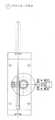
도 1은 직선 라인구동방식에 의한 페트병 생산 자동화 라인을 나타내는 전체도면 이다.
도1에서 보는 바와 같이 직선 라인구동방식에 의한 페트병 생산 자동화 라인은 사출기 에서 생산된 프리폼을 엘리베이터 피더 유닛의 호퍼에 대량 투입하며 이를 프리폼 정렬기에서 프리폼을 정렬하는 엘리베이터 피더부①, 1차 스토퍼와 2차 스토퍼에 의해 준비된 프리폼을 한 개씩 경사면과 가로 방향으로 이송 시켜주는 프리폼 스토퍼와 셔틀피더부②, 이송된 프리폼을 좌·우·상·하·180도로 이송 ·반전 시켜주는 1차 프리폼 반전장치부③, 이송된 프리폼을 할로겐램프에 의해 익혀주는 프리폼 히팅존부④ , 익힌 프리폼을 다시 한 번 좌·우·상·하·180도로 이송·반전 시켜주는 2차 프리폼 반전장치부⑤ , 프리폼을 재차 좌·우·상·하로 이송 ·반전 시켜주는 자동화 3차 프리폼 이송장치부⑥, 적절하게 익은 프리폼을 성형 금형으로 이송하는 피치 이송 구동부⑦, 이송된 프리폼을 금형 속으로 안착시키는 프리폼 운송 장치부⑧, 금형에 안착된 프리폼을 취입 성형하기 위한 페트 브로잉 금형 장치부⑨, 성형된 페트병을 스트레칭하기 위한 페트 브로잉 스트레칭 장치부⑩, 검사결과 페트병을 취출하는 페트병 취출 장치부⑪로 구성된 것을 특징으로 한다.
도 2에서 보듯이 엘리베이터 피더는 사출기 라인에서 생산된 프리폼을 호퍼로 이송시켜주는 승강기이다. 상기 엘리베이터 피더부①는 호퍼와 버켓 콘베어와 연결되고 상기 버켓 콘베어 일측에 프리폼 정렬기 연결되고 일측에 미끄럼 곡선판이 연결되고, 타단이 프리폼 스토퍼와 연결되는 것을 특징으로 한다. 더욱 상세하게는 엘리베이터 피더부①는 사출기 에서 생산된 프리폼을 엘리베이터 피더 유닛의 호퍼에 다량 투입하면 구동 모터와 어태치먼트 고무벨트로 이루어진 버켓 콘베어가 다량 투입된 프리폼을 고무벨트에 부착된 칸막이에 의해 소량 수직으로 운반하며, 수직 운반된 프리폼이 버켓 콘베어 끝 지점에 도달하여 프리폼 정렬기 투입부에 자유 낙하되면 2개의 환봉으로 이루어진 프리폼 정렬기는 두 축이 회전하면서 자유 낙하된 프리폼을 슬라이드 곡선 판 방향으로 이송시키고, 이때 자유 낙하된 프리폼은 무게중심에 의하여 2개의 환 봉 사이에 수직으로 위치되고, 프리폼 정렬기 에서 이송된 프리폼이 슬라이드 곡선판으로 자유낙하 하면 프리폼은 슬라이드 곡선 판 사이에 형성된 홈을 타고 프리폼 스토퍼 유닛으로 보내지고, 프리폼 스토퍼 유닛으로 유입된 프리폼은 스토퍼 자체에 설치된 2차 스토퍼에 의해서 정지된 상태로 일렬로 정렬되며, 이때 2차 스토퍼 위로 프리폼이 가득 차면 프리폼 정렬기와 버켓 콘베어는 동작을 멈추는 공정으로 연결된 프리폼을 정렬할 수 있도록 하는 것에 특징이 있다.
도3의 프리폼 스토퍼와 셔틀 피더부②는 프리폼 정렬기에서 정렬된 프리폼은 미끄럼 곡선판을 통하여 프리폼 스토퍼에 연결되고 프리폼 스토퍼 타단에 연결된 셔틀피터로 연결되며, 공급된 프리폼은 하나씩 셔틀피더의 홈에 끼워지고 이렇게 끼워진 4개의 프리폼이 셔틀피더의 홈이송대의 4개의 홈이 형성되어 있고, 상기 이송대의 타단에서 이송대를 지지하며 공압실린더와 슬라이딩바로 구성된다. 상세히 설명하면 프리폼은 직선운동 베어링과 에어 실린더에 장착된 셔틀 플레이트가 프리폼 스토퍼 방향으로 동작되면 프리폼 스토퍼의 1차 스토퍼가 전진함 과 동시에 2차 스토퍼는 후진하여 1차 스토퍼와 2차 스토퍼사이에 위치한 프리폼은 경사면 상에서 자유 상태가 되고, 2차 스토퍼가 후진을 완료하면 셔틀피더의 셔틀 플레이트는 에어실린더에 의하여 가로 방향으로 이동하면서 자유 상태가 된 프리폼을 셔틀 플레이트에 형성된 홈을 따라서 한 개씩 가로 방향으로 이송시키는 공정으로 연결된 프리폼을 경사면과 가로 방향으로 이송 시켜주는 특징이 있다.
도4의 1차 프리폼 반전장치부③는 셔틀피더와 일측이 연결되고, 타단이 프리폼 히팅존에 연결되고, 프리폼 그립퍼와 프리폼 반전용 회전부로 구성된 것을 특징으로 한다. 이것은 이송된 프리폼이 에어 동작용 180도 평행개폐 그립퍼에 잡히고, 잡힌 프리폼이 좌·우 이송 에어 실린더에 의하여 뒤로 빠지면 상승하며 반전용 에어 실린더에 의하여 180도 반전하여 회전하고 다시 하강하는 공정으로 연결된 프리폼을 좌·우·상·하·180도로 이송 ·반전 시켜주는 특징이 있다.
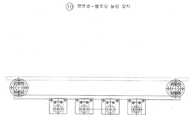
도5의 프리폼 히팅존부④는 프리폼이 목부, 고정부가 형성되고 4개의 프리폼을 동시에 이송할 수 있는 가로로 형성된 26조의 이송컨베이어에 좌우 중앙에 각각 할로겐등이 가로로, 각각 8열씩 이송컨베어 길이 방향으로 연속 설치되고, 컨베어 구동모터와 스프로켓과 도시하지 않은 아이들러 베어링에 의하여 1스탭씩 이동하는 것을 특징으로 한다. 또한 프리폼 히팅존부④는 프리폼을 이송시켜주는 인덱스 드라이브와 돌려주는 구동 모터를 돌리는 장치인 어태치먼트 체인, 프리폼이 좌우로 흔들리지 않게 고정시켜주는 프리폼지그, 프리폼을 돌려주는 프리폼 회전 유닛, 할로겐 램프로 이송된 프리폼을 익혀주는 할로겐램프, 할로겐 램프지지 유닛으로 구성된다. 상기와 같은 할로겐 램프는 할로겐에서 발생되는 자외선 영역의 광으로 페트병의 생산과정에서 살균효과를 가질 수 있도록 하는 것이다.
도6의 2차 프리폼 반전장치부⑤는 회전모터에 축연결을 통하여 연결된 회전측과 회전축의 축방향에 수직하게 일정한 간격으로 4조의 프리폼 그립퍼 고정암이 형성되고, 그립퍼 고정암의 회전축과 고정된 그립퍼 고정암의 타단에 프리폼 그립퍼가 형성되고, 상기 그립퍼는 공압에 의하여 90도회전하는 한 쌍의 핑거로 구성되며, 각 핑거는 프리폼을 잡을 수 있도록 원형의 수용부를 가진 것을 특징으로 한다. 다시 상세히 설명하면 이송된 프리폼이 에어 동작용 180도 평행개폐 그립퍼에 잡히고, 잡힌 프리폼이 좌·우 이송 에어 실린더에 의하여 뒤로 빠지면 상승하며 반전용 에어 실린더에 의하여 180도 반전하여 회전하고 다시 하강하는 공정으로 연결된 프리폼을 좌·우·상·하·180도로 이송·반전 시켜주는 것이다.
도7의 3차 프리폼 이송장치부⑥는 상하로 움직이는 공압실린더와 이에 연결되어 프리폼을 수용하는 4개의 프리폼 수용부가 형성된 프리폼 이송용 수용대 및 수용대 이송받침대 및 받침 베어링으로 구성된다. 즉 3차 프리폼 이송장치부⑥는 프리폼 가이드 지그 플레이트 가 이송되어온 익힌 프리폼을 정확한 위치에 고정시켜 잡아주고, 에어 실린더가 프리폼을 잡기 위해 상·하로 이동하고 하강하여 좌측으로 이동하면 프리폼 가이드 지그 플레이트가 상승하여 캐리어 쪽 고정 틀로 이송 시켜주는 지그 플레이트 안내용 보올 부시로 구성된 프리폼을 좌·우·상·하로 이송 ·반전 시켜주는 특징이 있다.
도8의 피치이송 구동부⑦는 한 쪽 방향 회전 기어가 장착된, 스프로켓 톱니모양의 기어와 스토퍼가 쌍으로 이루어져 일측으로만 회전가능한 스프로켓과 상기 스프로켓을 회전시키기 위하여, 공압실린더와 직선기어로 이루어진 스프로켓 구동부, 스프로켓을 정위치에서 회전시키고 고정시키기 위한 스프로켓 스토퍼 및 피치구동모터 작동감지센서로 구성된 것을 특징으로 한다.
즉 피치이송 구동부⑦는 페트병을 불어주기 위하여 성형 사출 하기 적절한 상태로 익힌 프리폼을 성형 금형으로 이송하는 포지셔널 원판 플레이트와 원판 플레이트 고정용 베어링 유닛, 마그네틱 클래치 유닛, 락 기어 유닛, 피니언기어 유닛, 직선운동 베어링유닛, 충격완화장치, 좌·우 이송용 에어실린더, 포지셔널 위치 결정용핀 과 핀가이드 및 핀 동작 에어실린더로 구성된다.
도9의 프리폼 운송 장치부⑧는 상기 피치이송-구동부⑦에 의하여 구동되며 프리폼의 목부를 잡는 그립퍼아암이 일정간격으로 형성된 체인과 상기체인을 스프로켓과, 아이들러 기어에 의하여 이동시키는 이송컨베어로 구성된다. 또한 상기 프리폼 운송 장치부⑧는 프리폼 운송 체인고정용 스프라켓 유닛, 4열 체인 유닛, 프리폼 지그와 지그장착용 플레이트, 체인 아이들러 유닛으로 구성된 것을 특징으로 한다.
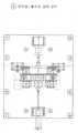
도10의 페트 브로잉 금형 장치부⑨는 4조로 형성된 페트병 금형의 상단부를 제1금형 하단부를 제2금형이라 하고 각각의 금형을 상하로 이동하는 제1, 제2실린더와 실린더 끝부분이 금형을 고정하기 위한 고정부와 금형이송 슬라이드로 구성된 것을 특징으로 한다. 상세히 설명하면 페트 브로잉 금형 장치부⑨는 이송된 프리폼을 금형 속으로 안착시켜주는 브로잉다이와 안착된 프리폼을 25kg/㎠의 고압으로 성형해주는 브로잉다이 고정용 불스터, 성형이 되면 금형을 열어주는 부로잉다이 여닫이용 좌·우 이송 에어 실린더, 브로잉다이 벌어짐 방지를 위한 핀과 핀 고정장치 및 브로잉다이 동작용 에어실린더, 브로잉다이 고정용 불스터 안내용 직선운동 베어링, 플레임 유닛으로 구성된 프리폼을 취입 성형하기 위한 것이다.
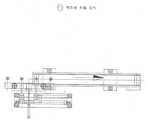
도11의 페트 브로잉 스트레칭 장치부⑩는 2조의 수직이동 공압실린더의 상부에 연결되고, 프리폼 주입구에 공기를 주입할 수 있는 주입부와 공기주입노즐이 4조 형성된 것을 특징으로 한다. 더욱 상세하게는 페트 브로잉 스트레칭 장치부⑩는 성형된 페트병을 이송하여주는 체인인 스트레치 용 샤프트 와 고압용 오링, 고압누수 방지용 패킹유닛, 스트레치 샤프트 동작용 에어 실린더, 고압누수 방지용 유닛 동작용 에어 실린더, 스트레치용 샤프트를 안내 해주는 안내보올 부시로 구성된 고압 및 고압누수 방지용 스트레칭이다.
도12의 페트병 취출 장치부⑪는 슬라이딩실린더와 슬라이딩 실린더의 상부에 수직하게 설치된 배출실린더 및 배출 실린더 끝부분에 설치된 배출그립퍼로 구성된 페트병 배출장치와, 배출장치 반대편에 수평으로 설치되어 페트병을 배출하는 배출컨베어로 구성된다. 즉 페트병 취출 장치부⑪는 페트병 취출 용 고정 그립퍼와 브라케트 및 상·하·전 ·후·좌·우로 이송하여주는 에어실린더에 의하여 취출 되고 취출된 페트병을 검사 과정으로 이송하여 주는 이송용 벨트 콘베어로 구성된 페트병 취출을 위한 3차 취출장치부인 것이다.
상기의 페트병 취출 장치부(11)에서 취출 된 페트병은 검사 과정을 거쳐 라벨기에 도착되고 라벨기 에서 상표를 붙이면 완제품이 된다.In order to achieve the above object, the present invention has the following configuration.
Hereinafter, exemplary embodiments of the present invention to which the above configuration is applied will be described in detail with reference to the accompanying drawings.
1 is an overall view showing a plastic bottle production line by a straight line drive method.
As shown in FIG. 1, the PET bottle production line using a straight line driving method puts a large amount of preforms produced in an injection machine into a hopper of an elevator feeder unit, and an
As shown in Figure 2, the elevator feeder is an elevator for transferring the preform produced in the injection machine line to the hopper. The
The preform stopper and the
The primary preform inverting unit part ③ of FIG. 4 is connected to one side of the shuttle feeder, and the other end is connected to the preform heating zone, and is characterized by consisting of a preform gripper and a preform reversing rotating unit. This means that the conveyed preform is caught by the 180 degree opening / closing gripper for air operation, and when the caught preform falls back by the left and right conveying air cylinders, it rises and is rotated 180 degrees by the reversing air cylinder, and then rotates again. It has the characteristic of transferring and reversing the left, right, up, down, 180 degrees.
The preform heating zone ④ of FIG. 5 has 26 sets of conveying conveyors in which the preforms are formed at the neck and the fixed part and can transport four preforms simultaneously. Continuously installed, characterized in that for moving by one step by the conveyor drive motor and the sprocket and the idler bearing (not shown). In addition, the preform heating zone ④ is transferred to the index drive that transfers the preform and the attachment chain that rotates the driving motor that returns the preform, the preform jig that fixes the preform so that it does not move left and right, the preform rotation unit that rotates the preform, and the halogen lamp. It consists of halogen lamp and halogen lamp support unit that learns the preform. The halogen lamp as described above is to have a bactericidal effect in the production process of PET bottles with light in the ultraviolet region generated from halogen.
The secondary preform inverting unit ⑤ of FIG. 6 is provided with four sets of preform gripper fixing arms at regular intervals perpendicular to the axial direction of the rotating side and the rotating shaft connected to the rotating motor, and fixed to the rotating shaft of the gripper fixing arm. A preform gripper is formed at the other end of the gripper fixing arm, and the gripper is composed of a pair of fingers rotated by 90 degrees by pneumatic pressure, and each finger has a circular receiving portion to hold the preform. In detail, the conveyed preform is caught by the 180 degree parallel opening and closing gripper for air operation, and the preform is lifted when the preform falls out by the left and right conveying air cylinders, and is rotated by 180 degrees by the inverting air cylinder. It transfers and reverses the preform connected by left, right, up, down and 180 degrees.
7 is composed of a pneumatic cylinder moving up and down and a preform conveyance receiving base having four preform accommodating parts for accommodating the preform, and a receiving support and a bearing bearing. That is, the 3rd preform feeder unit ⑥ holds and holds the cooked preform to which the preform guide jig plate has been transported in the correct position, and when the air cylinder moves up and down to catch the preform, and descends to the left, the preform guide jig plate is moved. It has the characteristic of conveying and reversing the preform consisting of a bowl bush for guiding the jig plate, which is lifted up and transported to the carrier-side fixing frame.
The pitch feed drive unit ⑦ of FIG. 8 is composed of a pair of sprocket toothed gears and a stopper equipped with a one-way rotating gear, and a sprocket composed of a pneumatic cylinder and a linear gear to rotate the sprocket and the sprocket which can rotate only on one side. The drive unit, a sprocket stopper for rotating and fixing the sprocket in position, and pitch drive motor operation sensor is characterized in that composed of.
That is, the pitch feed driving unit ⑦ is a positive negative plate for conveying the preforms prepared in a suitable state for molding injection to blow the PET bottle, a bearing unit for fixing the negative plate, a magnetic clutch unit, a lock gear unit, a pinion gear unit, It consists of a linear motion bearing unit, impact relief device, left and right transfer air cylinders, position positioning pins and pin guides and pin operated air cylinders.
The
In the PET blowing
The PET blowing stretching device part of FIG. 11 is connected to the upper part of two sets of vertically moving pneumatic cylinders, and is characterized in that four injection parts and an air injection nozzle are formed to inject air into the preform inlet. More specifically, the PET Blowing Stretching Unit is a chain for conveying molded PET bottles, a stretch shaft and a high pressure O-ring, a high pressure leak preventing packing unit, a stretch shaft operating air cylinder, a high pressure leak preventing unit operating air cylinder It is a high pressure and high pressure leak prevention stretch consisting of a guide bush which guides the stretch shaft.
12 is a bottle dispensing device consisting of a sliding cylinder, a discharge cylinder installed vertically on the upper portion of the sliding cylinder, and a discharge gripper installed at the end of the discharge cylinder, and horizontally disposed opposite the discharge device to discharge the PET bottle. Consists of an exhaust conveyor. In other words, the PET bottle ejecting device is a conveying belt conveyor that transfers the PET bottle taken out by the fixed gripper and the bracket and the air cylinder which transfers up, down, front, back, left and right to the inspection process. It is a tertiary take-out unit for taking out the PET bottle consisting of.
The PET bottle taken out from the PET bottle taking out
삭제delete
삭제delete
삭제delete
삭제delete
삭제delete
삭제delete
삭제delete
삭제delete
삭제delete
삭제delete
삭제delete
삭제delete
삭제delete
이상에서 상술 한 바와 같이 본 발명의 페트병 생산 자동화 라인은 4개의 프리폼을 일체로 성형할 수 있도록, 프리폼의 투입후에 4개의 프리폼을 동시에 이송할 수 있는 자동화 라인을 구축하였으며, 각 라인의 동작을 일치시켜 동작케 함으로써 연속적으로 고속의 생산이 가능하고, 프리폼의 이송 길이를 최적화하여 할로겐 이외의 별도의 프리폼 가열장치가 필요 없도록 하였으며, 할로겐에서 발생되는 자외선 영역의 광으로 페트병이 생산과정에서 살균효과를 가질 수 있도록 하였으며, 자동화 시스템을 모두 공압을 사용하여 청결하고 깨끗한 페트병 생상공장을 실현하였으며, 금형의 교체사용으로 다양한 형상의 페트병을 생산 할 수 있고, 특히 센서감지식 구동방법이어서, 페트병 피치이송부의 피치이동감지센서의 시스템에 전체 생산라인이 작동하게 되어, 신뢰성 있는 제품을 생산할 수 있는 특징이 있다.As described above, the PET bottle production automation line of the present invention has built an automation line capable of simultaneously transporting four preforms after the preform is inputted so that the four preforms can be integrally formed, and the operation of each line is consistent. It enables continuous high speed production by optimizing the feeding length of the preform, eliminating the need for a separate preform heating device other than halogen. It is possible to have a plastic bottle production plant that is clean and clean by using pneumatics and all automation systems, and it is possible to produce PET bottles of various shapes by replacing and using molds, and in particular, it is a sensor-sensing driving method. The entire production line operates on the system of the pitch shift sensor. As a result, there is a feature that can produce a reliable product.
Claims (12)
Translated fromKoreanPriority Applications (1)
| Application Number | Priority Date | Filing Date | Title |
|---|---|---|---|
| KR1020030080784AKR100547566B1 (en) | 2003-11-14 | 2003-11-14 | PET Bottle Production Automation Line |
Applications Claiming Priority (1)
| Application Number | Priority Date | Filing Date | Title |
|---|---|---|---|
| KR1020030080784AKR100547566B1 (en) | 2003-11-14 | 2003-11-14 | PET Bottle Production Automation Line |
Publications (2)
| Publication Number | Publication Date |
|---|---|
| KR20030091911A KR20030091911A (en) | 2003-12-03 |
| KR100547566B1true KR100547566B1 (en) | 2006-01-31 |
Family
ID=32389426
Family Applications (1)
| Application Number | Title | Priority Date | Filing Date |
|---|---|---|---|
| KR1020030080784AExpired - Fee RelatedKR100547566B1 (en) | 2003-11-14 | 2003-11-14 | PET Bottle Production Automation Line |
Country Status (1)
| Country | Link |
|---|---|
| KR (1) | KR100547566B1 (en) |
Cited By (1)
| Publication number | Priority date | Publication date | Assignee | Title |
|---|---|---|---|---|
| KR101865094B1 (en)* | 2017-09-14 | 2018-06-07 | 신우코스텍(주) | A manufacturing apparatus for a container comprising 3d shape |
Families Citing this family (7)
| Publication number | Priority date | Publication date | Assignee | Title |
|---|---|---|---|---|
| KR100674220B1 (en)* | 2006-10-16 | 2007-01-24 | (주)피스코엔지니어링 | Neck Crystallization System for PET Bottles |
| KR100808661B1 (en)* | 2006-12-12 | 2008-03-06 | 동아정밀공업(주) | Transparent PET Container Manufacturing Equipment |
| CN109502295A (en)* | 2018-12-12 | 2019-03-22 | 佛山德亚创智科技有限公司 | Turning conveyor structure and overturning transport device |
| CN110216852B (en)* | 2019-07-03 | 2024-04-16 | 佛山华新恒丰聚酯包装有限公司 | Bottle cap injection molding leakage detecting production line |
| CN115123812B (en)* | 2022-07-09 | 2024-03-01 | 福鼎市艺双自动化设备制造有限公司 | Automatic conveying and processing device for front and back surfaces of workpiece and control method thereof |
| CN117415611B (en)* | 2023-12-19 | 2024-03-29 | 山东德晟机器人股份有限公司 | Automatic assembly line of distance rod assembly |
| CN118789715B (en)* | 2024-09-12 | 2024-11-15 | 安徽绿德孚环保科技有限公司 | Hierarchical recycle device and waste plastic integrated treatment system |
- 2003
- 2003-11-14KRKR1020030080784Apatent/KR100547566B1/ennot_activeExpired - Fee Related
Cited By (2)
| Publication number | Priority date | Publication date | Assignee | Title |
|---|---|---|---|---|
| KR101865094B1 (en)* | 2017-09-14 | 2018-06-07 | 신우코스텍(주) | A manufacturing apparatus for a container comprising 3d shape |
| WO2019054743A1 (en)* | 2017-09-14 | 2019-03-21 | 신우코스텍(주) | Apparatus for manufacturing container having three-dimensional shape |
Also Published As
| Publication number | Publication date |
|---|---|
| KR20030091911A (en) | 2003-12-03 |
Similar Documents
| Publication | Publication Date | Title |
|---|---|---|
| TWI619598B (en) | Method for forming container with handle | |
| CN103228423B (en) | Injection stretch blow molding equipment and molded product heating equipment | |
| JP6150410B2 (en) | Blow molding machine | |
| US8684724B2 (en) | Plant for blow-moulding plastic containers, particularly bottles | |
| JP6118529B2 (en) | Molded product delivery device and blow molding device | |
| US8781616B2 (en) | Robotic unscrambler and method | |
| KR100547566B1 (en) | PET Bottle Production Automation Line | |
| KR20110033856A (en) | Forming units for equipment for blow molding plastic containers, especially bottles | |
| CN113056359B (en) | Blow molding machine and method for controlling a blow molding machine | |
| US20110121497A1 (en) | Plant for blow-moulding plastic containers, particularly bottles | |
| KR20110033855A (en) | Equipment for blow molding plastic containers, especially bottles | |
| CN101015955A (en) | Blow molding method and blow molding equipment | |
| JP5852450B2 (en) | Preform conveying apparatus and conveying method thereof | |
| JPH0957824A (en) | Parison conveying device | |
| JPH0970828A (en) | Preform cooling and transporting apparatus | |
| CN212314685U (en) | Bottle embryo arrangement loading attachment | |
| JPH08224775A (en) | Method and apparatus for blow molding | |
| JP3442141B2 (en) | Blow molding equipment | |
| TR201900859T4 (en) | Machine for molding and blow molding of containers obtained from corresponding parisons of a thermoplastic material. | |
| CN120246546A (en) | Automatic bottle sorting equipment | |
| JPH065867Y2 (en) | Preform feeder | |
| JPH072346A (en) | Conveyed object branching device on conveyor | |
| HK1184414B (en) | Injection stretch blow molding device and molded part heating device |
Legal Events
| Date | Code | Title | Description |
|---|---|---|---|
| A201 | Request for examination | ||
| PA0109 | Patent application | St.27 status event code:A-0-1-A10-A12-nap-PA0109 | |
| PA0201 | Request for examination | St.27 status event code:A-1-2-D10-D11-exm-PA0201 | |
| PG1501 | Laying open of application | St.27 status event code:A-1-1-Q10-Q12-nap-PG1501 | |
| D13-X000 | Search requested | St.27 status event code:A-1-2-D10-D13-srh-X000 | |
| D14-X000 | Search report completed | St.27 status event code:A-1-2-D10-D14-srh-X000 | |
| E902 | Notification of reason for refusal | ||
| PE0902 | Notice of grounds for rejection | St.27 status event code:A-1-2-D10-D21-exm-PE0902 | |
| R17-X000 | Change to representative recorded | St.27 status event code:A-3-3-R10-R17-oth-X000 | |
| P11-X000 | Amendment of application requested | St.27 status event code:A-2-2-P10-P11-nap-X000 | |
| P13-X000 | Application amended | St.27 status event code:A-2-2-P10-P13-nap-X000 | |
| E701 | Decision to grant or registration of patent right | ||
| PE0701 | Decision of registration | St.27 status event code:A-1-2-D10-D22-exm-PE0701 | |
| GRNT | Written decision to grant | ||
| PR0701 | Registration of establishment | St.27 status event code:A-2-4-F10-F11-exm-PR0701 | |
| PR1002 | Payment of registration fee | St.27 status event code:A-2-2-U10-U11-oth-PR1002 Fee payment year number:1 | |
| PG1601 | Publication of registration | St.27 status event code:A-4-4-Q10-Q13-nap-PG1601 | |
| LAPS | Lapse due to unpaid annual fee | ||
| PC1903 | Unpaid annual fee | St.27 status event code:A-4-4-U10-U13-oth-PC1903 Not in force date:20090124 Payment event data comment text:Termination Category : DEFAULT_OF_REGISTRATION_FEE | |
| PC1903 | Unpaid annual fee | St.27 status event code:N-4-6-H10-H13-oth-PC1903 Ip right cessation event data comment text:Termination Category : DEFAULT_OF_REGISTRATION_FEE Not in force date:20090124 | |
| P22-X000 | Classification modified | St.27 status event code:A-4-4-P10-P22-nap-X000 | |
| P22-X000 | Classification modified | St.27 status event code:A-4-4-P10-P22-nap-X000 |