KR100547302B1 - Absolute Steering Angle Measurement Method of Vehicle Steering Shaft - Google Patents
Absolute Steering Angle Measurement Method of Vehicle Steering ShaftDownload PDFInfo
- Publication number
- KR100547302B1 KR100547302B1KR1020030079320AKR20030079320AKR100547302B1KR 100547302 B1KR100547302 B1KR 100547302B1KR 1020030079320 AKR1020030079320 AKR 1020030079320AKR 20030079320 AKR20030079320 AKR 20030079320AKR 100547302 B1KR100547302 B1KR 100547302B1
- Authority
- KR
- South Korea
- Prior art keywords
- value
- obtaining
- rotating body
- steering shaft
- angle
- Prior art date
- Legal status (The legal status is an assumption and is not a legal conclusion. Google has not performed a legal analysis and makes no representation as to the accuracy of the status listed.)
- Expired - Fee Related
Links
Images


Classifications
- B—PERFORMING OPERATIONS; TRANSPORTING
- B62—LAND VEHICLES FOR TRAVELLING OTHERWISE THAN ON RAILS
- B62D—MOTOR VEHICLES; TRAILERS
- B62D15/00—Steering not otherwise provided for
- B62D15/02—Steering position indicators ; Steering position determination; Steering aids
- B62D15/021—Determination of steering angle
- B62D15/0215—Determination of steering angle by measuring on the steering column
- G—PHYSICS
- G01—MEASURING; TESTING
- G01B—MEASURING LENGTH, THICKNESS OR SIMILAR LINEAR DIMENSIONS; MEASURING ANGLES; MEASURING AREAS; MEASURING IRREGULARITIES OF SURFACES OR CONTOURS
- G01B21/00—Measuring arrangements or details thereof, where the measuring technique is not covered by the other groups of this subclass, unspecified or not relevant
- G01B21/22—Measuring arrangements or details thereof, where the measuring technique is not covered by the other groups of this subclass, unspecified or not relevant for measuring angles or tapers; for testing the alignment of axes
- G—PHYSICS
- G01—MEASURING; TESTING
- G01D—MEASURING NOT SPECIALLY ADAPTED FOR A SPECIFIC VARIABLE; ARRANGEMENTS FOR MEASURING TWO OR MORE VARIABLES NOT COVERED IN A SINGLE OTHER SUBCLASS; TARIFF METERING APPARATUS; MEASURING OR TESTING NOT OTHERWISE PROVIDED FOR
- G01D5/00—Mechanical means for transferring the output of a sensing member; Means for converting the output of a sensing member to another variable where the form or nature of the sensing member does not constrain the means for converting; Transducers not specially adapted for a specific variable
- G01D5/02—Mechanical means for transferring the output of a sensing member; Means for converting the output of a sensing member to another variable where the form or nature of the sensing member does not constrain the means for converting; Transducers not specially adapted for a specific variable using mechanical means
- G01D5/04—Mechanical means for transferring the output of a sensing member; Means for converting the output of a sensing member to another variable where the form or nature of the sensing member does not constrain the means for converting; Transducers not specially adapted for a specific variable using mechanical means using levers; using cams; using gearing
Landscapes
- Engineering & Computer Science (AREA)
- Physics & Mathematics (AREA)
- General Physics & Mathematics (AREA)
- Chemical & Material Sciences (AREA)
- Combustion & Propulsion (AREA)
- Transportation (AREA)
- Mechanical Engineering (AREA)
- Length Measuring Devices With Unspecified Measuring Means (AREA)
- Measurement Of Length, Angles, Or The Like Using Electric Or Magnetic Means (AREA)
Abstract
Translated fromKoreanDescription
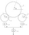
Translated fromKorean도1은 본 발명의 바람직한 하나의 실시예를 나타내고 있다.Figure 1 shows one preferred embodiment of the present invention.
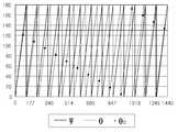
도2는 조향축의 조향각에 따른 Ψ′과 θ′의 관계를 나타낸다.2 shows the relationship between Ψ 'and θ' according to the steering angle of the steering axis.
도3은 본 발명에 의한 방법으로 Φ1을 구하는 과정을 도식적으로 나타내고 있다.Fig. 3 schematically shows a process for obtaining? 1 by the method according to the present invention.
도4는 본 발명에 의한 방법을 통해 i를 간단하게 구하는 과정을 도식적으로 나타내고 있다.Figure 4 schematically shows the process of simply finding i through the method according to the invention.
*도면의 주요부분에 대한 설명** Description of the main parts of the drawings *
1...조향축, 2...제1회전체, 3...제2회전체, 4,5...각도센서, 6...연산회로1 ... steering shaft, 2 ... 1 rotor, 3 ... 2 rotor, 4, 5 angle sensor, 6 ...
본 발명은 차량용 조향축의 조향각을 측정하는 방법에 관한 것으로서, 더욱 상세하게는 상기 조향축이 회전함에 따라 소정의 회전비로 회전하는 두 개의 회전체를 이용하여 조향축의 조향각을 측정하는 방법에 관한 것이다.The present invention relates to a method of measuring a steering angle of a steering shaft for a vehicle, and more particularly, to a method of measuring a steering angle of a steering shaft by using two rotors rotating at a predetermined rotation ratio as the steering shaft rotates.
조향축의 절대 조향각을 측정함에 있어서는 그 측정범위가 360°를 넘기 때문에 단지 각도센서만을 이용하여 이를 측정하는 것이 용이하지 않은 문제가 있다.In measuring the absolute steering angle of the steering shaft, since the measuring range exceeds 360 °, it is not easy to measure it using only the angle sensor.
또한, 조향축의 조향각은 차량의 시동을 켰을 때 그것이 임의의 각도 위치에 있더라도 바로 측정될 수 있어야 한다.In addition, the steering angle of the steering shaft should be able to be measured immediately even when it is in any angular position when the vehicle is turned on.
미국특허 제5930905호와 제6466889B1호에서는 조향축이 회전함에 따라 일정한 회전비로 회전하는 제1회전체와 제2회전체의 회전각을 측정하여 이로부터 조향축의 절대 조향각을 얻는 방법을 소개하고 있다.US Patent Nos. 5930905 and 6466889 B1 introduce a method of measuring the rotation angles of the first and second rotating bodies that rotate at a constant rotation ratio as the steering shaft rotates, thereby obtaining an absolute steering angle of the steering shaft.
상기에서 제1회전체 및 제2회전체의 절대 회전각은 각각 Ψ=Ψ′+ iΩ와 θ=θ′+ jΩ로 표현될 수 있는데(여기서, Ω는 상기 Ψ′와 θ′를 측정하는 각도센서의 측정범위를 나타내고, i는 제1회전체의 절대 회전각 Ψ가 상기 Ω를 넘어선 횟수를 나타내는 정수로서 제1회전체의 주기수를 나타내고, j는 마찬가지로 제2회전체의 주기수를 나타냄), 상기의 미국특허는 모두 Ψ′와 θ′를 측정하여 소정의 계산과정을 거쳐 조향축의 절대 조향각 Φ를 얻고 있다.The absolute rotation angles of the first and second rotating bodies may be expressed as Ψ = Ψ ′ + iΩ and θ = θ ′ + jΩ, where Ω is an angle measuring the Ψ ′ and θ ′, respectively. Indicate the measuring range of the sensor, i is an integer indicating the number of times the absolute rotation angle Ψ of the first rotating body exceeds the Ω, and represents the number of cycles of the first rotating body, j is similarly the number of cycles of the second rotating body The above-mentioned US patents measure both Ψ 'and θ' and obtain the absolute steering angle Φ of the steering shaft through a predetermined calculation process.
상기의 미국특허 제5930905호에서는 상기의 Ψ′와 θ′를 측정하고, 그 측정된 값을 Ψ, θ 및 Φ 상호간의 기하학적 관계로부터 도출되는 아래와 같은 특정한 식(1)에 대입한 후 이를 반올림하여 정수값 k를 얻은 다음, 그 k와 Ψ′ 및 θ′을 이용해 아래의 식(2)를 통해 Φ를 계산하여 구하게 된다.In U.S. Patent No. 5930905, the Ψ 'and θ' are measured, and the measured values are substituted into the following specific equation (1) derived from the geometric relationship between Ψ, θ, and Φ, and then rounded. After the integer value k is obtained, Φ is calculated by using Equation (2) below using k, Ψ 'and θ'.


(여기서, m은 제1회전체의 기어 이빨 수, m+1은 제2회전체의 기어 이빨 수, n은 조향축에 형성된 기어 이빨 수로서 조향축에 제1회전체 및 제2회전체가 치합되어 있다.)(Where m is the number of gear teeth of the first rotating body, m + 1 is the number of gear teeth of the second rotating body, n is the number of gear teeth formed on the steering shaft, and the first and second rotating bodies are It is engaged.)
한편, 상기의 미국특허 제6466889B1호에서는 두 회전체의 절대 회전각 차이인 Ψ-θ과 제1회전체(제2회전체가 될 수도 있음)의 i의 관계를 이용해 i를 직접 구하여 조향각 Φ를 얻고 있다. 여기서, Ψ-θ는 측정하여 얻은 Ψ′-θ′이 음의 수인 경우에는 Ω를 더하여 구하고, 그렇지 않은 경우에는 그 값을 그대로 유지함으로서 구하고 있다. 그 다음 Ψ-θ와 i의 관계로부터 i를 계산하고, Ψ′과 i로부터 계산된 Ψ를 이용해 조향축의 절대 조향각 Φ를 얻는 방법을 취하고 있다.Meanwhile, in the above-mentioned US Patent No. 6466889 B1, the steering angle Φ is obtained by directly obtaining i using a relationship between Ψ-θ, which is the absolute rotation angle difference between the two rotors, and i of the first rotor (which may be the second rotor). Getting Here,?-? Is obtained by adding? When the measured? '-?' Is a negative number, and otherwise is obtained by keeping the value as it is. Next, i is calculated from the relationship between Ψ-θ and i, and the absolute steering angle Φ of the steering axis is obtained using Ψ calculated from Ψ 'and i.
이때, 각도센서의 측정범위는 Ω이므로 조향축이 최대로 회전되어 i가 k1이 되었을 때 상기의 회전각 차이 Ψ-θ는 Ω와 같거나 그보다 작아야 한다(단, 상기의 미국특허 제6466889B1호에서는 Ω와 같도록 하였음). 즉, 조향축이 최대로 회전될 때까지 상기의 회전각 차이 Ψ-θ는 0°에서 Ω까지 연속적으로 변하며, i는 0에서 k1까지 단계적으로 변하게 된다.In this case, since the measurement range of the angle sensor is Ω, when the steering shaft is rotated to the maximum and i is k1, the rotation angle difference Ψ-θ must be equal to or smaller than Ω (but, in the above-mentioned US Patent No. 6466889 B1). Equal to Ω). That is, the rotation angle difference Ψ-θ continuously changes from 0 ° to Ω until the steering shaft is rotated to the maximum, and i changes stepwise from 0 to k1.
여기서, 미국특허 제6466889B1호에서는 상기의 회전각 차이 Ψ-θ이 0°에서 Ω까지 연속적으로 변할 때, i는 0에서 k1까지 연속적으로 변하여 선형비례관계이 있는 것으로 가정하고, 상기 두 개의 회전각을 측정하여 얻은 Ψ-θ에 k1/Ω을 곱하여 얻은 값으로부터 그 값보다 작은 최대의 정수값을 취하여 i를 얻고 있다. 예컨대, Ψ-θ에 k1/Ω을 곱하여 얻은 값이 5.9…인 경우 i는 5가 된다.Here, US Pat. No. 6,684,89B1 assumes that when the rotation angle difference Ψ-θ continuously changes from 0 ° to Ω, i is continuously changed from 0 to k1 and has a linear proportional relationship. I is obtained by taking the largest integer value smaller than the value from the value obtained by multiplying the measured Ψ-θ by k1 / Ω. For example, a value obtained by multiplying Ψ-θ by k1 / Ω is 5.9... If is i is 5.
이와 같은 미국특허 제6466889B1호의 방법은 Ψ-θ의 최대값이 Ω보다 클 수 없기 때문에 i-j는 항상 0 또는 1이어야 하며, 2이상이 될 수 없는 제한을 받는다.This method of US Pat. No. 6,267,89B1 is i-j always must be 0 or 1 since the maximum value of Ψ-θ cannot be greater than Ω, and is limited to not more than two.
본 발명은 360° 범위를 넘어 회전하는 조향축의 절대 조향각을 측정하는 방법으로서, 측정오차로 인한 에러가 적고, 계산량이 현저히 감소하는 방법을 제공하는데 그 목적이 있다.The present invention provides a method for measuring an absolute steering angle of a steering shaft rotating over a 360 ° range, wherein the error due to a measurement error is small and the calculation amount is significantly reduced.
또한, 본 발명은 Ψ-θ를 이용하지 않고, 제1회전체의 주기수 i나 또는 제2회전체의 주기수 j를 직접 구할 수 있는 방법을 제공한다. i 또는 j를 한번 얻고 나면, 그 다음부터는 간단한 계산과정을 통해 얻어 낼 수 있어 유용하다.The present invention also provides a method in which the period number i of the first rotating body or the period number j of the second rotating body can be directly obtained without using Ψ-θ. Once you get i or j, it is useful to get it through a simple calculation.
본 발명에 의해 차량 조향축의 조향각을 측정하는 방법은, 조향축이 회전함에 따라 r1의 회전비로 회전하는 제1회전체와 상기 조향축이 회전함에 따라 r2의 회전비로 회전하는 제2회전체를 이용한다.According to the present invention, a method for measuring a steering angle of a vehicle steering shaft uses a first rotating body rotating at a rotation ratio of r1 as the steering shaft rotates and a second rotating body rotating at a rotation ratio of r2 as the steering shaft rotates. .
제1회전체의 절대 회전각 Ψ는 Ψ′+ iΩ로 표현될 수 있고, 제2회전체의 절대 회전각 θ는 θ′+ jΩ로 표현될 수 있으며, 각도센서를 이용해 상기의 Ψ′과 θ′을 측정하게 된다. 여기서, Ω는 상기 Ψ′와 θ′를 측정하는 각도센서의 측정범위를 나타내고, i는 제1회전체의 절대 회전각 Ψ가 상기 Ω를 넘어선 횟수를 나타내는 정수로서 제1회전체의 주기수를 나타내고, j는 마찬가지로 제2회전체의 주기수를 나타낸다. 즉, 제1회전체의 절대 회전각 Ψ는 측정범위가 Ω인 각도센서를 이용해 측정되는 상대 회전각 Ψ′과 주기수 i 및 Ω의 곱의 합으로 표현될 수 있고, 제2회전체의 절대 회전각 θ도 같은 방식으로 표현될 수 있다.The absolute rotation angle Ψ of the first rotating body may be represented by Ψ '+ iΩ, and the absolute rotation angle θ of the second rotating body may be represented by θ' + jΩ, and the above mentioned Ψ 'and θ using an angle sensor. 'Is measured. Here, Ω represents the measurement range of the angle sensor for measuring the Ψ 'and θ', i is an integer indicating the number of times the absolute rotation angle Ψ of the first rotating body exceeds the Ω, and the period number of the first rotating body J represents the number of cycles of a 2nd rotating body similarly. That is, the absolute rotation angle Ψ of the first rotating body may be expressed as the sum of the product of the relative rotation angle Ψ ′ and the period i and Ω measured using an angle sensor having a measuring range of Ω, and the absolute of the second rotating body. The rotation angle θ can also be expressed in the same way.
상기에서 각도센서는 측정범위 Ω는 180°나 360°또는 그 외의 다른 값이 될 수 있다. 그리고, 상기의 각도센서는 Ψ′과 θ′을 측정할 수 있는 것이라면 접촉식이건 비접촉식이건 관계없이 어떠한 종류라도 될 수 있다.In the above-described angle sensor, the measuring range Ω may be 180 °, 360 °, or other values. The angle sensor may be of any kind, whether contact or non-contact, as long as it can measure Ψ 'and θ'.
본 발명에서는 측정범위가 Ω인 각도센서를 이용해 Ψ′과 θ′의 측정값 ΨM′및 θM′를 얻은 다음, Ψ′ 및 θ′의 관계로부터 상기 ΨM′에 대응될 수 있는 다수의 θ′들을 계산하여 그 계산값인 다수의 θc′들을 얻는다. 그리고, 상기 다수이 θc′들과 θM′을 비교하여 상기 제1회전체의 주기수 i를 얻고, 상기 i를 이용해 제1회전체의 절대 회전각 Ψ을 얻은 후 Ψ와 Φ의 관계로부터 조향축의 조향각 Φ(이를 Φ1이라 함)를 얻게 된다.A plurality of in the present invention can correspond with the angle sensor measures range Ω from the relation Ψ 'and θ' measured values ΨM 'and θM' and then, Ψ 'and θ' obtained in the above ΨM 'θ's are calculated to obtain a plurality of θc's. In addition, the plurality compares θc 'with θM ′ to obtain a period i of the first rotatable body, and obtains an absolute rotation angle Ψ of the first rotatable body using the i. The steering angle Φ (which is called Φ1) is obtained.
여기서, ΨM′및 θM′를 측정하여 조향축의 조향각 Φ를 얻는 매 순간마다 상기의 과정을 거쳐 제1회전체의 주기수 i를 구하도록 할 수도 있지만, 바람직하게는 처음에 상기와 같은 방법으로 i를 얻은 이후부터는 단지 ΨM′의 이전값과 현재값을 비교하여 i의 이전값에 1을 더하거나 뺌으로서 i의 현재값을 얻는 것이 바람직하다. 이는 i가 1만큼 증가하는 순간 ΨM′의 절대값은 Ω에서 0으로 변하고, i가 1만큼 감소하는 순간 ΨM′의 절대값은 0에서 Ω로 변하게 되는 사실을 이용한 것이다. 즉, i가 변하게 되는 순간을 전후해서 ΨM′은 큰 폭으로 변하게 됨을 이용한 것이다. 이와 같은 과정을 통해 i를 구하게 되면 계산량이 감소하는 장점도 있지만, 더욱 중요하게는 θM′에 포함된 측정 오차가 i에 영향을 주지 않게 된다.Here, it is possible to determine the period number i of the first rotating body through the above process every time the steering angle Φ of the steering shaft is obtained by measuring ΨM ′ and θM ′, but preferably, After obtaining i, it is desirable to compare the present value with the previous value of ΨM 'and add 1 to the previous value of i or obtain the present value of i by 뺌. This takes advantage of the fact that as i increases by 1 the absolute value of ΨM ′ changes from Ω to 0, and as i decreases by 1, the absolute value of ΨM ′ changes from 0 to Ω. In other words, before and after the moment i changes, ΨM ′ is changed to a large width. In this process, i can be obtained by reducing i, but more importantly, the measurement error included in θM ′ does not affect i.
더욱 바람직하게는, Ψ′ 및 θ′의 관계로부터 상기 θM′에 대응될 수 있는 다수의 Ψ′들을 계산하여 그 계산값인 다수의 Ψc′들을 얻고, 상기 다수의 Ψc′들과 ΨM′을 비교하여 상기 제2회전체의 j를 얻은 다음, 상기 j를 이용해 제2회전체의 절대 회전각 θ을 얻은 후 θ와 Φ의 관계로부터 조향축의 조향각 Φ(이를 Φ2라 함)를 추가로 얻는다. 그리고, 상기 Φ1과 Φ2의 평균값을 조향축의 조향각 Φ로 하는 것이 바람직하다. 이와 같이 평균을 하게 되면, ΨM′및 θM′에 포함되는 측정 오차가 서로 상쇄되어 소멸되는 효과가 있다. 여기서, Φ1과 Φ2는 측정 오차가 전혀 없는 경우에는 같은 값이 되지만, 측정 오차가 전혀 없을 수 없기 때문에 다른 값이 될 것이다.More preferably, a plurality of Ψ's, which may correspond to θM ', are calculated from the relationship of Ψ' and θ 'to obtain a plurality of Ψc' which is the calculated value, and the plurality of Ψc 'and ΨM ' To obtain j of the second rotating body, and then obtain the absolute rotation angle θ of the second rotating body using the j, and then obtain steering angle Φ (which is called Φ2) of the steering shaft from the relationship between θ and Φ. . Then, it is preferable to set the average value of
또한, 여기서 매 측정순간 j를 구함에 있어서도, 상기 i를 구하는 경우와 마찬가지로 θM′의 이전값과 현재값을 비교하여 j의 이전값에 1을 더하거나 뺌으로서 j의 현재값을 구하는 것이 바람직하다. 그리고, 이와 같은 방법으로 i, j를 구하여 Φ1과 Φ2를 얻는 과정에서 Φ1과 Φ2의 차이가 특정값 이상으로 크게 되면, 상기와 같이 Ψc′ 및 θc′를 계산하고 이를 ΨM′및 θM′과 비교하는 방법으로 i, j를 다시 구하도록 하는 것이 바람직하다.In addition, it is preferable to obtain the present value of j by adding 1 to the previous value of j or comparing the current value of θM 'by comparing the previous value of θM ′ with the same value as in the case of i. . In the process of obtaining i and j to obtain
이하에서는 도면에 나타난 실시예를 통해 보다 상세하게 설명하도록 한다. 도1에는 조향축(1)과 이에 치합되어 있는 제1회전체(2) 및 제2회전체(3)와, 상기 제1회전체 및 제2회전체의 상대회전각 Ψ′및 θ′을 측정할 각도센서(4,5)와, 상 기 센서로부터 측정된 ΨM′및 θM′를 입력받아 소정의 연산을 수행하여 Φ를 결과로 출력하는 연산회로(6)가 나타나 있다. 여기서 조향축과 제1회전체의 회전비 r1은 7/4이고, 조향축과 제2회전체의 회전비 r2는 6.5/4이다(도1에 나타난 기어 이빨 수는 정확하지 않을 수 있음). 도2에는 조향축이 총4회전하는 동안 상기 제1회전체의 상대회전각 Ψ′과 상기 제2회전체의 상대회전각 θ′의 관계를 나타내고 있다. 여기서, x축은 조향각 Φ이고, Ω는 180°이다. 그리고, 도3에는 상기 Ψ′및 θ′을 측정하여 조향축의 절대 조향각 Φ를 구하는 과정을 도식적으로 나타내고 있다.Hereinafter will be described in more detail through the embodiment shown in the drawings. 1 shows the
여기서, 도2와 같은 제1회전체 및 제2회전체의 상대회전각 관계는 조향축의 조향각을 변화시키면서 제1회전체의 상대회전각 Ψ′과 제2회전체의 상대회전각 θ′을 측정함으로서 시험적으로 얻는 것이 가장 바람직하다.Here, the relative rotation angle relationship between the first and second rotors as shown in Figure 2 measures the relative rotation angle Ψ 'of the first rotor and the relative rotation angle θ' of the second rotor while changing the steering angle of the steering shaft. It is most preferable to obtain a test by doing so.
도3에서 보이듯이 각도센서를 이용해 ΨM′및 θM′을 얻으면, 상기의 ΨM′으로부터 도2와 같은 관계를 이용해 상기 ΨM′에 대응될 수 있는 다수의 θC′들을 계산하여 얻는다(도3에서 θCi′는 i에 대응하는 θC′을 의미함). 그리고, 이와 같이 얻은 다수의 θC′들 중 θM′과 가장 근접한 것을 찾음으로서 i를 구한다. 예컨대, ΨM′은 130°이고, θM′은 105°라고 가정하면, 도2와 같은 관계에서 Ψ′이 130°일 때 이에 대응될 수 있는 θC′은 i가 0에서 13까지 증가함에 따라 도2의 그래프에서 점으로 표시되고 있는 바와 같이 순차적으로 120.7°, 107.9°, 95°, 82.1°, 69.3°, 56.4°, 43.6°, 30.7°, 17.9°, 5°, 172.1°, 159.3°, 146.4°, 133.6°등이 된다. 이와 같은 다수이 θC′들 중 105°인 θM′과 가장 근접한 것은 107.9°이며, 이때 i는 1이 된다.Get the ΨM 'and θM' with the angle sensor as shown in Figure 3, wherein the ΨM 'from FIG using the relation such as 2 the ΨM' is obtained by computing a number of θC ', which can correspond to (ΘCi ′ in FIG. 3 means θC ′ corresponding to i). Then, i is found by finding the closest to θM ′ among the plurality of θC ′ thus obtained. For example, assuming that ΨM ′ is 130 ° and θM ′ is 105 °, θC ′, which may correspond to when Ψ ′ is 130 ° in the relationship as shown in FIG. 2, increases i from 0 to 13. 212 °, 107.9 °, 95 °, 82.1 °, 69.3 °, 56.4 °, 43.6 °, 30.7 °, 17.9 °, 5 °, 172.1 °, 159.3 ° sequentially , 146.4 °, 133.6 ° and so on. Many of these closest to θM ′, 105 ° of θC ′, are 107.9 °, where i is 1.
그리고, 이와 같이 얻은 i와 ΨM′을 이용해 조향축의 조향각 Φ1을 계산하면 다음과 같다.The

매 측정 순간마다 i를 상기와 같은 방식으로 구할 수도 있지만, 상기와 같은 과정을 통해 i를 한번 구하고 난 다음부터는 단지 ΨM′의 현재값을 그 이전값과 비교하여 i의 이전값에 1을 더하거나 뺌으로서 간단하게 구하도록 하는 것이 바람직하다. 예컨대, ΨM′의 현재값에서 이전값을 뺀 값 ΔΨM′이 어떤 음의 특정값보다 작으면 i의 이전값에 1을 더하고, 어떤 양의 특정값보다 크면 1을 빼며, 그렇지 않으면 i의 이전값을 그대로 유지하도록 하여 i의 현재값을 얻는다.At every instant of measurement, i can be obtained in the same way as above, but after i has been obtained once through this process, only the current value of ΨM ′ is compared with its previous value and 1 is added to the previous value of i, or It is preferable to make it simple as. For example, if the value ΔΨM ′ minus the previous value from the current value of ΨM ′ is less than any negative specific value, add 1 to the previous value of i; subtract 1 if it is greater than any positive specific value; Get the current value of i by keeping the previous value.
이를 도4를 통해 보다 구체적으로 살펴본다. 도4에 보이듯이 ΔΨM′이 특정값 -As보다 작으면 i의 이전값에 1을 더하고, As보다 크면 1을 빼며, 그렇지 않으면 i의 이전값을 그대로 유지하여 i의 현재값을 얻는다. 여기서, i의 이전값은 3, 상기의 특정값 As는 170°, ΨM′의 이전값은 179°, ΨM′의 현재값은 1°라고 가정하면, ΔΨM′는 -178°가 되어 -170°보다 작으므로 현재의 i는 4가 된다. 그리고, 여기서 만약 ΨM′의 이전값은 1°, ΨM′의 현재값은 179°라고 가정하면, Δ ΨM′는 178°가 되어 170°보다 작으므로 현재의 i는 2가 된다.This will be described in more detail with reference to FIG. 4. As shown in Fig. 4, when ΔΨM 'is smaller than the specific value -As, 1 is added to the previous value of i, and when 1 is larger than As, 1 is subtracted, otherwise, the previous value of i is maintained as it is to obtain the current value of i. Here, when the previous value of i is 3, the current value of the specific value of the As is 170 °, ΨM 'is the previous value of 179 °, ΨM' is assumed to be 1 °, ΔΨM 'is a -178 ° Since i is less than -170 °, the current i is 4. In this case, if the previous value of ΨM 'is 1 ° and the current value of ΨM ' is 179 °, Δ ΨM ′ is 178 °, which is smaller than 170 °, so the current i becomes 2.
이와 같이 i의 현재값이 결정되면, ΨM′의 현재값과 함께 식(5)에 대입하여 Φ1의 현재값을 얻는다.When the present value of i is determined as described above, the present value of φ1 is obtained by substituting Eq. (5) together with the present value of ΨM '.
한편, 상기에서 ΨM′으로부터 다수의 θC′들을 계산하여 i를 얻는 것과 마찬가지로 θM′으로부터 다수의 ΨC′들을 계산하여 j를 얻을 수 있고, 또, θM′의 이전값과 현재값을 비교하여 j의 현재값을 얻을 수 있다. 그리고, 이로부터 조향축의 조향각 Φ2는 아래의 식을 통해 얻을 수 있다.On the other hand, just as to obtain a i by calculating the "number of θC from" ΨM in the above can be obtained for j to calculate a 'plurality of ΨC from "θM, Further, θM' previous and current values of We can compare j to get the current value of j. From this, the

더욱 바람직하게는 상기의 Φ1과 Φ2를 평균하여 조향축의 조향각을 얻는 것이다. 이로써 ΨM′과 θM′에 포함될 수 있는 측정오차에 의한 조향각의 에러를 최소화할 수 있다.More preferably, the steering angle of the steering shaft is obtained by averaging
그리고, 여기서 Φ1과 Φ2의 차이가 크게 벌어져 특정값 이상으로 되면, 이는 허용할 수 있는 수준 이상으로 에러가 많이 발생한 것이므로, 도3에 나타난 것과 같은 과정을 통해 다시 i, j를 구하여 Φ1과 Φ2를 얻고 이를 평균하여 조향각을 얻는 것이 바람직하다.If the difference between Φ1 and Φ2 is greater than a certain value, the error occurs more than the allowable level. Therefore, i and j are obtained through the same process as shown in FIG. 3 to obtain Φ1 and Φ2. It is desirable to obtain and average the steering angle.
본 발명에 의하면, Ψ-θ를 이용하지 않고도 i 또는 j를 직접 구하여 조향각을 구할 수 있다. i 또는 j가 한번 구해지면, 그 다음부터는 간단한 계산과정을 통 해 i, j를 구할 수 있어 유용하다.According to the present invention, steering angle can be obtained by directly obtaining i or j without using Ψ-θ. Once i or j is found, it is useful to get i and j through a simple calculation.
i를 한번 구하고 나면, 단지 ΨM′의 이전값과 현재값만을 비교하여 i를 구할 수 있기 때문에 계산량을 감소시킬 수 있으며, 더욱 중요하게는 θM′에 포함되는 측정 오차의 영향을 받지 않고 i를 구할 수 있다. 그리고, 만약 이때 θM′을 측정하는 각도센서가 고장 등으로 그 기능을 수행하지 못하더라도 조향각을 측정할 수 있는 효과가 있다.Once i is found, i can be calculated by comparing only the previous and current values of ΨM ′, thus reducing the amount of computation. More importantly, i is not affected by the measurement error included in θM ′. Can be obtained. And, in this case, even if the angle sensor measuring θM ′ does not perform its function due to failure, etc., the steering angle can be measured.
또한, 본 발명에 의하면, 절대 조향각을 측정하기 위해 정수화시키는 과정(예컨대 미국특허 제5930905호에서 k를 구하는 과정이나 미국특허 제6466889B1호에서 i를 구하는 과정)을 제거하여 에러를 감소시킬 수 있다. 즉, 정수화시키는 과정에서 ±1의 에러가 발생하여 절대조향각에 큰 에러가 포함되게 되는 문제를 제거할 수 있다.In addition, according to the present invention, the error may be reduced by eliminating the process of determining the absolute steering angle (for example, obtaining k in US Pat. No. 5930905 or obtaining i in US Pat. That is, an error of ± 1 occurs during the integerization process so that a large error may be included in the absolute steering angle.
Claims (5)
Translated fromKoreanPriority Applications (2)
| Application Number | Priority Date | Filing Date | Title |
|---|---|---|---|
| KR1020030079320AKR100547302B1 (en) | 2003-11-11 | 2003-11-11 | Absolute Steering Angle Measurement Method of Vehicle Steering Shaft |
| US10/748,152US7050895B2 (en) | 2003-11-11 | 2003-12-31 | Method for measuring the absolute steering angle of steering shaft for vehicle |
Applications Claiming Priority (1)
| Application Number | Priority Date | Filing Date | Title |
|---|---|---|---|
| KR1020030079320AKR100547302B1 (en) | 2003-11-11 | 2003-11-11 | Absolute Steering Angle Measurement Method of Vehicle Steering Shaft |
Publications (2)
| Publication Number | Publication Date |
|---|---|
| KR20050045306A KR20050045306A (en) | 2005-05-17 |
| KR100547302B1true KR100547302B1 (en) | 2006-01-26 |
Family
ID=34545831
Family Applications (1)
| Application Number | Title | Priority Date | Filing Date |
|---|---|---|---|
| KR1020030079320AExpired - Fee RelatedKR100547302B1 (en) | 2003-11-11 | 2003-11-11 | Absolute Steering Angle Measurement Method of Vehicle Steering Shaft |
Country Status (2)
| Country | Link |
|---|---|
| US (1) | US7050895B2 (en) |
| KR (1) | KR100547302B1 (en) |
Families Citing this family (9)
| Publication number | Priority date | Publication date | Assignee | Title |
|---|---|---|---|---|
| KR100547302B1 (en)* | 2003-11-11 | 2006-01-26 | 현대모비스 주식회사 | Absolute Steering Angle Measurement Method of Vehicle Steering Shaft |
| KR100528644B1 (en)* | 2003-12-23 | 2005-11-15 | 현대모비스 주식회사 | Method for measuring the absolute steering angle of the steering shaft for a vehicle |
| KR100528645B1 (en)* | 2004-01-15 | 2005-11-15 | 현대모비스 주식회사 | Method for measuring the absolute steering angle of steering shaft for vehicle |
| KR100792668B1 (en)* | 2006-04-19 | 2008-01-09 | 대성전기공업 주식회사 | Wheel absolute angle detection method |
| CN101534630A (en)* | 2006-05-24 | 2009-09-16 | Tt电子技术有限公司 | Multiturn rotational sensor |
| KR100765087B1 (en)* | 2006-12-01 | 2007-10-09 | 현대모비스 주식회사 | Vehicle steering angle sensor assembly |
| CN101966856A (en)* | 2010-09-26 | 2011-02-09 | 昌辉汽车电气系统(安徽)有限公司 | Automobile steering wheel rotating angle measurement method |
| CN102435164B (en)* | 2011-09-20 | 2013-10-16 | 北京经纬恒润科技有限公司 | Absolute rotator rotation angle measurement method and absolute rotator rotation angle measurement device |
| CN107662637B (en)* | 2017-09-29 | 2019-07-30 | 株洲易力达机电有限公司 | A kind of automobile electric power-assisted steering disk angle recognition system |
Family Cites Families (8)
| Publication number | Priority date | Publication date | Assignee | Title |
|---|---|---|---|---|
| DE19506938A1 (en) | 1995-02-28 | 1996-08-29 | Bosch Gmbh Robert | Method and device for measuring the angle of a rotatable body |
| DE19849554C1 (en) | 1998-10-27 | 2000-03-02 | Ruf Electronics Gmbh | Method to determine absolute position with displacement and angle transducers; involves using two mechanically coupled sensors with output signals with numbers of periods different by one |
| EP1321745A4 (en)* | 2000-09-25 | 2005-09-07 | Tokai Rika Co Ltd | Rotating angle detector |
| KR100547302B1 (en)* | 2003-11-11 | 2006-01-26 | 현대모비스 주식회사 | Absolute Steering Angle Measurement Method of Vehicle Steering Shaft |
| KR20050045305A (en)* | 2003-11-11 | 2005-05-17 | 현대모비스 주식회사 | Method for measuring the absolute steering angle of steering shaft for vehicle by using a data table |
| KR100610380B1 (en)* | 2003-11-11 | 2006-08-09 | 현대모비스 주식회사 | Absolute Steering Angle Measurement Method of Vehicle Steering Shaft |
| KR100528644B1 (en)* | 2003-12-23 | 2005-11-15 | 현대모비스 주식회사 | Method for measuring the absolute steering angle of the steering shaft for a vehicle |
| KR100528645B1 (en)* | 2004-01-15 | 2005-11-15 | 현대모비스 주식회사 | Method for measuring the absolute steering angle of steering shaft for vehicle |
- 2003
- 2003-11-11KRKR1020030079320Apatent/KR100547302B1/ennot_activeExpired - Fee Related
- 2003-12-31USUS10/748,152patent/US7050895B2/ennot_activeExpired - Fee Related
Also Published As
| Publication number | Publication date |
|---|---|
| US20050102078A1 (en) | 2005-05-12 |
| US7050895B2 (en) | 2006-05-23 |
| KR20050045306A (en) | 2005-05-17 |
Similar Documents
| Publication | Publication Date | Title |
|---|---|---|
| KR100610380B1 (en) | Absolute Steering Angle Measurement Method of Vehicle Steering Shaft | |
| JP3792718B2 (en) | Angle measurement method for rotating body | |
| KR100528644B1 (en) | Method for measuring the absolute steering angle of the steering shaft for a vehicle | |
| JP4241012B2 (en) | Rotation angle detector | |
| KR100547302B1 (en) | Absolute Steering Angle Measurement Method of Vehicle Steering Shaft | |
| US7366636B2 (en) | Rotational angle detector | |
| KR100528645B1 (en) | Method for measuring the absolute steering angle of steering shaft for vehicle | |
| CN106443072A (en) | Centrifugal acceleration field tumbling calibration method for line accelerometer | |
| KR20050045305A (en) | Method for measuring the absolute steering angle of steering shaft for vehicle by using a data table | |
| CN115257777B (en) | A wheel speed measurement method, device and equipment | |
| JP7000263B2 (en) | Initial setting method and initial setting device | |
| KR100629796B1 (en) | Absolute steering angle or torque measurement method using optical method | |
| JP4794509B2 (en) | Device for detecting the rotational position of a rotating body using a resolver | |
| KR100610384B1 (en) | Absolute steering angle and torque measurement method and measuring device. | |
| JP5096399B2 (en) | Rotation angle detector | |
| JPH11190606A (en) | Rotation quantity measuring method and rotation quantity measuring device | |
| JP3638827B2 (en) | Error correction value creation device | |
| CN102435164B (en) | Absolute rotator rotation angle measurement method and absolute rotator rotation angle measurement device | |
| JPH02186231A (en) | Apparatus and method for calibrating wheel balancer | |
| JP2548355Y2 (en) | Axle torque measuring device | |
| JPH0585842B2 (en) | ||
| JP2021071444A (en) | Rotation angle detector | |
| JP3903735B2 (en) | Moving distance and position detecting device for moving body | |
| JP2001280970A (en) | Attitude measurement device | |
| KR20210016120A (en) | Apparatus and method for calibrating gyro-sensor |
Legal Events
| Date | Code | Title | Description |
|---|---|---|---|
| A201 | Request for examination | ||
| PA0109 | Patent application | St.27 status event code:A-0-1-A10-A12-nap-PA0109 | |
| PA0201 | Request for examination | St.27 status event code:A-1-2-D10-D11-exm-PA0201 | |
| R18-X000 | Changes to party contact information recorded | St.27 status event code:A-3-3-R10-R18-oth-X000 | |
| R18-X000 | Changes to party contact information recorded | St.27 status event code:A-3-3-R10-R18-oth-X000 | |
| D13-X000 | Search requested | St.27 status event code:A-1-2-D10-D13-srh-X000 | |
| PG1501 | Laying open of application | St.27 status event code:A-1-1-Q10-Q12-nap-PG1501 | |
| D14-X000 | Search report completed | St.27 status event code:A-1-2-D10-D14-srh-X000 | |
| E902 | Notification of reason for refusal | ||
| PE0902 | Notice of grounds for rejection | St.27 status event code:A-1-2-D10-D21-exm-PE0902 | |
| P11-X000 | Amendment of application requested | St.27 status event code:A-2-2-P10-P11-nap-X000 | |
| P13-X000 | Application amended | St.27 status event code:A-2-2-P10-P13-nap-X000 | |
| E701 | Decision to grant or registration of patent right | ||
| PE0701 | Decision of registration | St.27 status event code:A-1-2-D10-D22-exm-PE0701 | |
| GRNT | Written decision to grant | ||
| PR0701 | Registration of establishment | St.27 status event code:A-2-4-F10-F11-exm-PR0701 | |
| PR1002 | Payment of registration fee | St.27 status event code:A-2-2-U10-U11-oth-PR1002 Fee payment year number:1 | |
| PG1601 | Publication of registration | St.27 status event code:A-4-4-Q10-Q13-nap-PG1601 | |
| PR1001 | Payment of annual fee | St.27 status event code:A-4-4-U10-U11-oth-PR1001 Fee payment year number:4 | |
| PR1001 | Payment of annual fee | St.27 status event code:A-4-4-U10-U11-oth-PR1001 Fee payment year number:5 | |
| PR1001 | Payment of annual fee | St.27 status event code:A-4-4-U10-U11-oth-PR1001 Fee payment year number:6 | |
| PR1001 | Payment of annual fee | St.27 status event code:A-4-4-U10-U11-oth-PR1001 Fee payment year number:7 | |
| FPAY | Annual fee payment | Payment date:20130111 Year of fee payment:8 | |
| PR1001 | Payment of annual fee | St.27 status event code:A-4-4-U10-U11-oth-PR1001 Fee payment year number:8 | |
| PN2301 | Change of applicant | St.27 status event code:A-5-5-R10-R13-asn-PN2301 St.27 status event code:A-5-5-R10-R11-asn-PN2301 | |
| FPAY | Annual fee payment | Payment date:20131231 Year of fee payment:9 | |
| PR1001 | Payment of annual fee | St.27 status event code:A-4-4-U10-U11-oth-PR1001 Fee payment year number:9 | |
| LAPS | Lapse due to unpaid annual fee | ||
| PC1903 | Unpaid annual fee | St.27 status event code:A-4-4-U10-U13-oth-PC1903 Not in force date:20150121 Payment event data comment text:Termination Category : DEFAULT_OF_REGISTRATION_FEE | |
| PC1903 | Unpaid annual fee | St.27 status event code:N-4-6-H10-H13-oth-PC1903 Ip right cessation event data comment text:Termination Category : DEFAULT_OF_REGISTRATION_FEE Not in force date:20150121 | |
| R18-X000 | Changes to party contact information recorded | St.27 status event code:A-5-5-R10-R18-oth-X000 |