KR100545266B1 - Folding brush of the vacuum cleaner - Google Patents
Folding brush of the vacuum cleanerDownload PDFInfo
- Publication number
- KR100545266B1 KR100545266B1KR1020030072873AKR20030072873AKR100545266B1KR 100545266 B1KR100545266 B1KR 100545266B1KR 1020030072873 AKR1020030072873 AKR 1020030072873AKR 20030072873 AKR20030072873 AKR 20030072873AKR 100545266 B1KR100545266 B1KR 100545266B1
- Authority
- KR
- South Korea
- Prior art keywords
- brush
- auxiliary
- vacuum cleaner
- folding
- auxiliary brush
- Prior art date
- Legal status (The legal status is an assumption and is not a legal conclusion. Google has not performed a legal analysis and makes no representation as to the accuracy of the status listed.)
- Expired - Fee Related
Links
Images


Classifications
- A—HUMAN NECESSITIES
- A47—FURNITURE; DOMESTIC ARTICLES OR APPLIANCES; COFFEE MILLS; SPICE MILLS; SUCTION CLEANERS IN GENERAL
- A47L—DOMESTIC WASHING OR CLEANING; SUCTION CLEANERS IN GENERAL
- A47L9/00—Details or accessories of suction cleaners, e.g. mechanical means for controlling the suction or for effecting pulsating action; Storing devices specially adapted to suction cleaners or parts thereof; Carrying-vehicles specially adapted for suction cleaners
- A47L9/02—Nozzles
- A47L9/06—Nozzles with fixed, e.g. adjustably fixed brushes or the like
- A—HUMAN NECESSITIES
- A47—FURNITURE; DOMESTIC ARTICLES OR APPLIANCES; COFFEE MILLS; SPICE MILLS; SUCTION CLEANERS IN GENERAL
- A47L—DOMESTIC WASHING OR CLEANING; SUCTION CLEANERS IN GENERAL
- A47L9/00—Details or accessories of suction cleaners, e.g. mechanical means for controlling the suction or for effecting pulsating action; Storing devices specially adapted to suction cleaners or parts thereof; Carrying-vehicles specially adapted for suction cleaners
- A47L9/02—Nozzles
Landscapes
- Engineering & Computer Science (AREA)
- Mechanical Engineering (AREA)
- Nozzles For Electric Vacuum Cleaners (AREA)
- Electric Vacuum Cleaner (AREA)
Abstract
Translated fromKoreanDescription
Translated fromKorean도 1은 종래기술에 의한 접이식 브러시의 구성을 나타낸 평면도,1 is a plan view showing a configuration of a folding brush according to the prior art,
도 2는 종래기술에 의한 접이식 브러시가 각진 모서리를 청소할 경우 좌우몸체의 회전상태를 나타낸 예시도,Figure 2 is an exemplary view showing a rotating state of the left and right body when the folding brush according to the prior art to clean the angled corners,
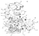
도 3은 본 발명에 의한 진공청소기의 접이식 브러시의 분해 사시도,3 is an exploded perspective view of a folding brush of the vacuum cleaner according to the present invention;
도 4는 본 발명에 의한 모서리 브러시와 전방 흡입덕트 부재의 결합관계를 확대하여 나타낸 저면 사시도,Figure 4 is a bottom perspective view showing an enlarged coupling relationship between the edge brush and the front suction duct member according to the present invention;
도 5는 본 발명에 의한 진공청소기의 접이식 브러시의 보조 브러시의 내부를 일부 절개하여 나타낸 요부 확대도,Figure 5 is an enlarged view of the main portion showing a part of the inside of the auxiliary brush of the folding brush of the vacuum cleaner according to the present invention,
도 6은 본 발명에 의한 진공청소기의 접이식 브러시의 보조 브러시의 내부를 일부 절개하여 신장상태일 경우의 내부를 나타낸 도면,Figure 6 is a view showing the inside of the extended state by partially cutting the inside of the auxiliary brush of the folding brush of the vacuum cleaner according to the present invention,
도 7은 본 발명에 의한 진공청소기의 접이식 브러시의 상부 브러시 커버를 제거한 상태의 사시도,7 is a perspective view of a state in which the upper brush cover of the folding brush of the vacuum cleaner according to the present invention is removed;
도 8은 본 발명에 의한 진공청소기의 접이식 브러시의 상부 브러시 커버를 제거한 상태의 보조 브러시가 접힌 상태의 사시도,8 is a perspective view of a state in which an auxiliary brush is folded in a state where an upper brush cover of a folding brush of a vacuum cleaner according to the present invention is removed;
도 9는 본 발명에 의한 진공청소기의 접이식 브러시의 하부 브러시 케이스를 제거한 사시도, 그리고,9 is a perspective view of removing the lower brush case of the folding brush of the vacuum cleaner according to the present invention, and
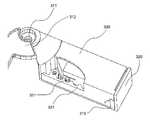
도 10은 본 발명에 의한 진공청소기의 접이식 브러시가 구석진 벽면을 청소하는 상태를 나타낸 도면이다.10 is a view showing a state in which the folding brush of the vacuum cleaner according to the present invention cleans the corner wall surface.
< 도면의 주요부분에 대한 부호의 설명 ><Description of Symbols for Major Parts of Drawings>
100; 접이식 브러시110; 하부 브러시 케이스100; Folding
111; 제 1 덕트112; 제 2 덕트111;
113; 공간부114; 연결관113;
120; 밀폐커버121; 제 1 덕트 커버120; Airtight
122; 제 2 덕트 커버123; 공간부 커버122;
130; 상부 브러시 커버200; 모서리 브러시130;
201; 헤드부202; 흡입포트201;
203; 걸림홈210; 모서리 브러시 몸체203;
220; 가이드 홈300; 보조 브러시220;
310; 보조 브러시 베이스320; 보조 브러시 몸체310;
330; 보조 브러시 커버330; Secondary brush cover
본 발명은 진공청소기에 관한 것으로, 보다 상세하게는 벽과 벽이 만나는 모서리 부분도 편리하게 청소할 수 있도록 브러시 몸체가 굴절될 수 있는 진공청소기의 접이식 브러시에 관한 것이다.The present invention relates to a vacuum cleaner, and more particularly, to a folding brush of a vacuum cleaner that can be deflected so that the brush body can be conveniently cleaned of the corner portion where the wall meets the wall.
도 1 및 도 2는 종래기술에 의한 접이식 브러시에 관해 도시한 것으로, 한국공개특허 특2003-0005545(2003.01.23)에 기재된 것이다.1 and 2 illustrate a folding brush according to the prior art, which is described in Korean Patent Laid-Open No. 2003-0005545 (2003.01.23).
즉, 도 1은, 종래기술에 의한 접이식 브러시의 구성을 나타낸 평면도를, 도 2는 각진 모서리를 청소할 경우 좌우몸체의 회전상태를 나타낸 예시도를 도시한 것으로, 상기 접이식 브러시는, 진공청소기의 흡입관(도시없음)과 연결되는 중앙몸체(1)와, 상기 중앙몸체(1)의 양측에 설치되는 좌,우몸체(2,2')와, 상기 중앙몸체(1)를 중심으로 좌,우몸체(2,2')가 회전한 후 원래의 위치로 복귀하는 복원력을 제공하는 스프링(3)으로 구성되었다.That is, Figure 1 is a plan view showing the configuration of the folding brush according to the prior art, Figure 2 shows an exemplary view showing the rotation state of the left and right body when cleaning the angular corner, the folding brush is a suction pipe of the vacuum cleaner Central body (1) connected to (not shown), left and right body (2, 2 ') installed on both sides of the central body (1), left, right body around the central body (1) (2,2 ') consists of a spring (3) that provides a restoring force to return to its original position after rotation.
상기 중앙몸체(1)에는 먼지등을 흡입하기 위한 흡입구(11)가 형성되고, 외주연 양측에는 좌,우몸체(2,2')의 회전을 안내하며 동시에 중앙몸체에 고정하기 위한 'T'형 가이드홈(미도시)이 형성되며, 그 상단에 좌,우 몸체(2,2')와 연결되는 스프링(3)의 일측이 회전가능하도록 스프링 가이드홀(미도시)이 형성되었다.The central body (1) is formed with a suction port (11) for sucking dust, etc., the outer periphery of both sides to guide the rotation of the left, right body (2, 2 ') and at the same time' T 'for fixing to the central body A type guide groove (not shown) is formed, and a spring guide hole (not shown) is formed at the upper end thereof so that one side of the
상기 좌,우몸체(2,2')의 일측에는 가이드홈(12)에 결합되는 돌출 가이드(22,22')가 형성되고, 그 상단에 스프링(3)이 끼워지는 스프링 연결홈(24,24')이 형성되며, 저면중앙에는 중앙몸체(1)의 흡입구(11)로 먼지를 안내하기 위한 흡입홈 (21,21')이 형성되었다. 또한 상기 돌출 가이드(22,22')의 하단에 차단막(23,23')을 형성하여 중앙몸체(1)와의 연결부위에서 흡입력이 손실되는 것을 방지하였다.One side of the left and right body (2, 2 ') is formed with a guide guide (22, 22') coupled to the guide groove 12, the
또한, 상기 중앙몸체(1)의 저면에 제 1,2,3 돌출부(14,14'14'')를 형성시키되, 도 2와 같이 흡입홈(21,21')과 평행한 일측변을 갖도록 제 2,3 돌출부(14',14'')를 형성하고, 상기 제 2 돌출부(14')와 제 3 돌출부(14'')의 중앙하단에 제 1 돌출부(14)를 형성하며, 상기 제 1,2 돌출부(14,14')에 돌출편(15,15')을 형성하여 우측몸체(2')에 형성된 차단막(23')은 돌출편(15,15')과 접하고, 좌측몸체(2)의 차단막(23)은 제 1,3 돌출부(14,14'')에 접하게 함으로서, 차단막(23,23')의 회전반경이 서로 다르게 하였다.In addition, the first, second and
상기 차단막(23,23')의 상면에는 차단막 가이드(23'')가 형성하고, 상기 차단막 가이드(23'')과 결합되는 차단막 가이드홈(17,17')을 중앙몸체(1)의 저면에 서로 다른 지름을 갖도록 형성하여 차단막(23,23')의 회전을 원활히 할 수 있도록 구성되었다.A
상기 스프링(3)은 2개의 토션스프링(Torsion spring)을 사용하여 일측이 중앙몸체(1)에 고정되고 타측이 좌,우몸체(2,2')의 스프링 연결홈(24,24')에 각각 끼워져 있어서 좌,우몸체(2,2')가 가구 또는 벽에 의해 회전할 경우 복원력을 제공하게 된다.The
그러나, 종래기술은 중앙몸체(1)와 좌,우몸체(2,2')의 구성으로 단순히 좌,우몸체(2,2')의 회전으로 각진 곳 모서리의 청소가 용이하도록 구성 되어 있으나 기존의 흡입관 사용에 문제가 따르고 좌,우몸체(2,2')의 확장이 불가능하여 넓은 부분을 손쉽게 청소하기가 어려우며, 중앙몸체(1)의 흡입구(11)부위에 형성된 스프링 가이드홀(13)과 스프링(3)이 흡입구(11)쪽에 위치해 있어 장기간 청소작업 시 흡입구(11)를 통해 유입 되는 먼지 등의 이물질에 의해 가이드홀(13)이 막히고 스프링(3)의 동작에 간섭을 줄 수 있다는 문제점이 있다.However, the prior art is composed of the central body (1) and the left, right body (2, 2 ') is configured to facilitate the cleaning of the corners of the angular place by simply rotating the left, right body (2,2') It is difficult to clean the wide part because it is impossible to expand the left and right bodies (2, 2 '), and the spring guide hole (13) formed at the inlet (11) of the central body (1) And the spring (3) is located on the inlet (11) side, the guide hole 13 is clogged by foreign matter, such as dust flowing through the inlet (11) during the long-term cleaning operation may interfere with the operation of the spring (3) There is a problem.
본 발명은 상기와 같은 점을 감안하여 안출된 것으로, 각진 모서리 청소시 브러시 몸체가 굴절되어 사용자 편이성을 향상시키며, 청소시 넓은 부분을 손쉽게 청소할 수 있도록, 사용자의 선택에 따라 브러시의 길이를 신장 및 수축 시킬 수 있도록 구조가 개선된 진공청소기의 접이식 브러시를 제공하는데 그 목적이 있다.The present invention has been made in view of the above, the brush body is refracted when cleaning the angular edge to improve the user convenience, and to easily clean a large portion during cleaning, the length of the brush according to the user's choice and extend and It is an object of the present invention to provide a folding brush of a vacuum cleaner having an improved structure to be able to shrink.
상기와 같은 문제점을 해결하기 위한 본 발명에 의한 진공청소기의 접이식 브러시는, 각진 모서리에 접촉할 경우, 브러시 몸체가 굴절되면서 벽면에 밀착되는 진공청소기의 접이식 브러시에 있어서, 그 내부에 복수의 흡입유로를 가지는 상부 및 하부 케이스; 상기 상부 및 하부 케이스의 양측면에 힌지결합되는 보조 브러시; 및 상기 보조 브러시의 회동에 연동하여, 전진 및 후퇴하는 모서리 브러시;를 포함하는 것을 특징으로 한다.The foldable brush of the vacuum cleaner according to the present invention for solving the above problems, in contact with the angular corner, in the foldable brush of the vacuum cleaner is in close contact with the wall while the brush body is bent, a plurality of suction oil therein Upper and lower cases having; Auxiliary brushes hinged to both sides of the upper and lower cases; And an edge brush which moves forward and backward in association with the rotation of the auxiliary brush.
본 발명의 바람직한 실시예에 의하면, 상기 흡입유로는, 상기 보조 브러시와 연결되는 제 1 덕트; 상기 모서리 브러시와 연결되는 제 2 덕트; 및 상기 제 1 및 제 2 덕트가 합류되는 공간부;를 포함하는 것이 좋다.According to a preferred embodiment of the present invention, the suction passage, the first duct connected to the auxiliary brush; A second duct connected to the edge brush; And a space part in which the first and second ducts are joined.
그리고, 상기 흡입유로는, 상기 하부 브러시 케이스 상에 상기 제 1 및 제 2 덕트가 상기 공간부에서 합류되도록 격벽으로 구획되어지며, 그 상측으로, 일체로 형성된 밀폐커버에 의해 상기 제 1 덕트, 제 2 덕트 및 공간부가 밀폐되는 것이 좋다.The suction flow passage is partitioned by partition walls such that the first and second ducts join in the space portion on the lower brush case, and the first duct and the first duct are formed by an airtight cover integrally formed thereon. 2 It is good that the duct and the space are sealed.
그리고, 상기 제 2 덕트에 가이드되면서, 상기 모서리 브러시의 전진 및 후 퇴에 연동하여 움직이는 전방 흡입덕트 부재;를 포함하는 것지 바람직하다.And, guided to the second duct, the front suction duct member moving in conjunction with the forward and backward of the edge brush; preferably includes.
그리고, 상기 전방 흡입덕트 부재는, 그 끝단에 걸림돌기가 형성되어, 상기 모서리 브러시에 마련된 걸림홈에 안착되어 상기 모서리 브러시의 전진 및 후퇴에 연동하여 함께 움직이는 것이 좋다.In addition, the front suction duct member has a locking protrusion formed at an end thereof, and may be seated in a locking groove provided in the corner brush to move together with the forward and backward movement of the edge brush.
또한, 상기 보조 브러시는, 상기 하부 브러시 케이스에 회동가능하게 설치되는 보조 브러시 베이스; 상기 보조 브러시 베이스에 길이방향으로 신장 가능하도록 결합되는 보조 브러시 몸체; 및 사이 보조 브러시 베이스에 결합되며, 상기 보조 브러시 몸체의 길이방향 이탈을 방지하는 보조 브러시 커버;를 포함할 수 있다.The auxiliary brush may further include: an auxiliary brush base rotatably installed on the lower brush case; An auxiliary brush body coupled to the auxiliary brush base to extend in a longitudinal direction; And an auxiliary brush cover coupled between the auxiliary brush bases and preventing longitudinal detachment of the auxiliary brush body.
그리고, 상기 보조 브러시는, 상기 보조 브러시 몸체의 일단에 돌출 형성된 걸림돌기; 및 상기 걸림돌기와 대응되는 보조 브러시 커버 내주면 상에 마련된 일정한 폭과 진폭을 가지는 복수의 걸림홈;을 구비하여, 상기 보조 브러시 몸체가 길이방향으로 신장 및 수축 될 때, 상기 걸림홈 각각의 폭 만큼씩 신장 및 수축되는 것이 바람직하다.The auxiliary brush may include: a locking protrusion protruding from one end of the auxiliary brush body; And a plurality of locking grooves having a predetermined width and amplitude provided on an inner circumferential surface of the auxiliary brush cover corresponding to the locking projections, when the auxiliary brush body is extended and contracted in the longitudinal direction, by the width of each of the locking grooves. It is preferred to stretch and contract.
또한, 상기 보조 브러시는, 초기위치로 보조 브러시를 탄성원복 시키기위해, 힌지결합부에 탄성부재가 설치되는 것이 좋다.In addition, the auxiliary brush, in order to elastically restore the auxiliary brush to the initial position, it is preferable that the elastic member is installed in the hinge coupling portion.
그리고, 상기 보조 브러시는, 각각의 보조 브러시가 나란한 상태일 경우, 상기 흡입유로와 연통되고, 보조 브러시가 회동될 경우, 상기 흡입유로와 차단될 수 있다.The auxiliary brush may be in communication with the suction channel when each auxiliary brush is in a side-by-side state, and may be blocked with the suction channel when the auxiliary brush is rotated.
그리고, 상기 모서리 브러시는, 끝단이 각지게 형성된 모서리 브러시 몸체; 상기 모서리 브러시 몸체 하부면에 형성된 흡입포트; 및 상기 보조 브러시가 연결 되는 가이드 홈;을 포함하는 것이 바람직하다.The edge brush may include: an edge brush body having an end formed at an angle; A suction port formed at a lower surface of the edge brush body; And a guide groove to which the auxiliary brush is connected.
이 때, 상기 보조 브러시는, 상기 가이드 홈에 안착되는 가이드 돌기를 가지는 링크부재;가 상기 힌지축에 인접된 위치에 설치되어, 상기 보조 브러시의 회동에 따라, 상기 모서리 브러시가 전진 및 후퇴할 수 있다.At this time, the auxiliary brush, the link member having a guide protrusion which is seated in the guide groove; is installed at a position adjacent to the hinge axis, the corner brush can be moved forward and backward according to the rotation of the auxiliary brush. have.
즉, 상기 가이드 홈은, 상기 보조 브러시 각각의 가이드 돌기를 동시에 수용하면서, 상기 보조 브러시가 회동하여 각각의 보조 브러시 사이의 각이 예각이 될 경우, 상기 모서리 브러시가 돌출되도록 상기 가이드 돌기의 회동 궤적과 대응되는 원주율을 가지도록 형성된다.That is, the guide groove, while receiving the guide projections of each of the auxiliary brush at the same time, when the auxiliary brush is rotated and the angle between the respective auxiliary brush is acute angle, the rotational trajectory of the guide projection so that the corner brush protrudes It is formed to have a circumference corresponding to.
이하 본 발명에 의한 진공청소기의 접이식 브러시에 대해 첨부된 도면과 함께 그 구조를 설명한다.Hereinafter, the structure of the folding brush of the vacuum cleaner according to the present invention together with the accompanying drawings.
도 3은 본 발명에 의한 진공청소기의 접이식 브러시의 분해 사시도를 나타낸 것이다.Figure 3 shows an exploded perspective view of the folding brush of the vacuum cleaner according to the present invention.
도시된 바와 같이, 본 발명에 의한 접이식 브러시(100)는, 제 1 및 제 2 덕트(111)(112)와, 공간부(113)를 가지는 하부 브러시 케이스(110)와, 상기 제 1 및 제 2 덕트(111)(112)와, 공간부(113)의 상측에 설치되어, 이들 각각을 밀폐하는 밀폐커버(120)와, 상부 브러시 케이스(130)를 포함한다.As shown, the
상기 하부 및 상부 브러시 케이스(110)(130)로 이루어지는 브러시 몸체의 전방에는, 상기 접이식 브러시(100)의 진행방향으로 전진 및 후퇴가 가능하도록 설치되는 모서리 브러시(200)가 설치된다.In front of the brush body formed of the lower and
그리고, 상기 하부 및 상부 브러시 케이스(110)(130)로 이루어지는 브러시 몸체의 좌우측 끝단에는 그 길이방향으로 신장 가능한 보조 브러시(300)가 상기 하부 브러시 케이스(110)에 마련된 힌지 수용부(115)에 힌지결합된다.In addition, at the left and right ends of the brush body including the lower and
상기 하부 브러시 케이스(110)는, 본 발명에 의한 접이식 브러시(100) 몸체의 하부면을 형성하는 것으로, 그 내부에 복수의 흡입유로를 구비한다. 각각의 흡입유로는, 상기 보조 브러시(300)와 연결되는 제 1 덕트(111)와, 상기 모서리 브러시(200)와 연결되는 제 2 덕트(112) 및 상기 제 1 및 제 2 덕트(111)(112)가 합류되는 공간부(113)를 가진다. 상기 상기 제 1 및 제 2 덕트(111)(112)는 상기 공간부(113)에서 합류되도록 격벽으로 구획되어지며, 상기 공간부(113)는, 상기 모서리 브러시(200) 및 보조 그러시(300)에서 흡입된 오물이 포함된 공기를 모아 연결관(114)에 전달하며, 상기 연결관(114)은, 미도시된 연장관과 플랙시블 호스 조립체를 통해 진공청소기 본체에 마련된 집진실로, 오물이 포함된 공기의 이동을 가이드한다. 상기 연결관(114)은, 축방향으로 회동가능하게 설치되는데, 이를 위해 그 연결부(114a)는 구 형성으로 마련되며, 상기 연결부(114a)의 외주면에는, 가이드링(114b)가 돌출형성되어, 상기 하부 브러시 케이스(110)와 후술할 밀폐커버(120)의 사이에 마련된 가이드 그루브(110a)를 따라 회동가능하게 설치된다. 따라서, 사용자는 상기 연결관을 축방향으로 자유롭게 되돌 시킬 수 있으며, 상기 가이드링(114b)에 의해 지지되는 연결부(114a)는 입체적으로 회동 가능하다.The
상기 제 1 및 제 2 덕트(111)(112)와 공간부(113)의 상측에는 밀폐커버(120)가 설치되어 이들 각각을 밀폐하는데, 바람직하게는, 상기 제 1 및 제 2 덕트(111)(112)와 공간부(113) 각각의 형상이 대응되는 일체로된 부재로 마련되는 것이 바람직하다. 즉, 상기 제 1 덕트(111)와 대응되는 제 1 덕트 커버(121)와, 상기 제 2 덕트(112)와 대응되는 제 2 덕트 커버(122) 및 상기 공간부(113)를 밀폐하는 공간부 커버(123)가 일체로된 부재로 형성되는 것이 좋다.An
상기 모서리 브러시(200)는, 모서리 브러시 몸체(210)와, 상기 모서리 브러시(200)와 보조 브러시(300)를 연결하는 가이드 홈(220)을 포함한다.The
상기 모서리 브러시 몸체(210)는, 도 4에 도시된 바와 같이, 전방을 향하는 끝단이 각지게 형성되며, 그 저면이 개구된 흡입포트(202)를 가지는 헤드부(201)와, 전방 흡입덕트 부재(230)를 결합하기 위한 걸림홈(203)을 포함한다. 전방 흡입 덕트 부재(230)는, 후에 설명한다.As shown in FIG. 4, the
상기 헤드부(201)는, 상기 보서리 브러시 몸체(210)의 가장 끝단을 이루는 것으로, 각진 모서리 청소를 위해 본 발명에 의한 접이식 브러시(100)의 전진방향을 형성하는 일단의 내각이 연직이 되도록 형성된다. 그리고, 그 저면은 개구된 흡입포트(202)로 형성하여, 피청소면과 대면하면서 오물이 포함된 공기를 청소기 본체에 마련된 집진실로 흡입하는 역할을 한다.The
상기 가이드 홈(220)은, 후술할 보조 브러시(300) 각각에 돌출형성된 가이드 돌기(312a)를 동시에 수용하면서, 상기 보조 브러시(300)가 회동하여 각각의 보조 브러시(300) 사이의 각이 예각이 될 경우, 상기 모서리 브러시(200)가 돌출되도록 상기 가이드 돌기(312a)의 회동 궤적과 대응되는 원주율을 가지도록 형성된다.The
상기 전방 흡입덕트 부재(230)는, 파이프 형상의 부재로서, 상기 제 2 덕트(112)에 가이드되면서, 상기 모서리 브러시(200)의 전진 및 후퇴에 연동하여 움직인다. 즉, 그 끝단에 걸림돌기(231)가 형성되어, 상기 걸림홈(203)에 끼워맞춤되어, 상기 모서리 브러시(200)의 전진 및 후퇴 동작에 연동되어 함께 움직일 수 있다. 상기 전방 흡입덕트 부재(230)에 의해, 상기 흡입포트(202)에서 흡입된 오물이 포함된 공기는, 상기 전방 흡입덕트 부재(230) 및 제 2 덕트(112)를 통해 공간부(113)로 이동할 수 있다.The front
상기 보조 브러시(300)는, 도 5 및 6에 도시된 바와 같이, 상기 하부 브러시 케이스(110)에 회동가능하게 설치되는 보조 브러시 베이스(310); 상기 보조 브러시 베이스(310)에 길이방향으로 신장 가능하도록 결합되는 보조 브러시 몸체(320); 및 사이 보조 브러시 베이스(310)에 결합되며, 상기 보조 브러시 몸체(320)의 길이방향 이탈을 방지하는 보조 브러시 커버(330);를 포함할 수 있다.The
상기 보조 브러시 베이스(310)는, 상기 하부 브러시 케이스(110)에 힌지결합되는 힌지축(311)과, 상기 모서리 브러시(200)에 마련된 상기 가이드 홈(220)에 안착되는 가이드 돌기(312a)를 가지는 링크부재(312);가 상기 힌지축(311)에 인접된 위치에 설치되어, 상기 보조 브러시(300)의 회동에 따라, 상기 모서리 브러시(200)가 전진 및 후퇴할 수 있도록 한다.The
상기 보조 브러시 몸체(320)는, 그 최초 결합위치에서 길이방향으로 신장 가능한데, 이를 위해, 상기 보조 브러시 몸체(320)의 일단에 돌출 형성된 걸림돌기(321); 및 상기 걸림돌기(321)와 대응되는 보조 브러시 커버(330) 내주면 상에 마련된 일정한 폭과 진폭을 가지는 복수의 걸림홈(331);을 구비하여, 상기 보조 브러시 몸체(320)가 길이방향으로 신장 및 수축 될 때, 상기 걸림홈(331) 각각 의 폭 만큼씩 신장 및 수축되는 것이 바람직하다.The
또한, 상기 보조 브러시(300)는, 초기위치로 보조 브러시(300)를 탄성원복 시키기위해, 힌지축(311)과 하부 브러시 케이스(110) 사이의 결합부에 탄성부재(116)가 설치되는 것이 좋다. 바람직하게는 상기 탄성부재(116)는 토션스프링으로 마련되는 것이 좋다.In addition, the
그리고, 상기 보조 브러시(300)는, 도 7에 도시된 바와 같이, 각각의 보조 브러시(300)가 나란한 상태일 경우, 상기 제 1 덕트(111)와 연통되고, 도 8 및 도 9에 도시된 바와 같이, 보조 브러시(300)가 회동될 경우, 상기 보조 브러시(300)와 상기 제 1 덕트(111)는 차단되어, 흡입은 상기 모서리 브러시(200)를 통해서만 이루어 진다.In addition, as shown in FIG. 7, the
이하, 본 발명에 의한 진공청소기의 접이식 브러시(100)의 동작을 첨부된 도면과 함께 설명한다.Hereinafter, the operation of the
상술한 바와 같이, 본 발명에 의한 접이식 브러시(100)는, 상부 및 하부 케이스(110)(130)로 형성된 브러시 몸체의 전면에, 각진 모서리를 청소할 수 있는 모서리 브러시(200)가 설치되며, 상기 모서리 브러시(200)는, 브러시 몸체의 양측에 힌지결합된 보조 브러시(300)의 회동에 연동하여 전진 및 후퇴 가능하다.As described above, the
따라서, 도 8에 도시된 화살표 방향으로, 상기 보조 브러시(300)가 회동하면, 상기 링크부재(312)에 마련된 가이드 돌기(312a)는, 상기 가이드 홈(220)을 따라 회동하면서, 상기 모서리 브러시(200)를 전방으로 전진할 수 있도록 밀어주게 되므로, 도시된 바와 같이, 상기 모서리 브러시(200)는, 전방으로 돌출되면서, 도 10에 도시된 바와 같이, 각진 모서리를 가지는 벽면(W)에 브러시 전체를 밀착시킬 수 있다.Therefore, when the
즉, 사용자는 종래와 같이 모서리 청소를 위해 틈새 브러시와 같은 보조 브러시로 흡입툴을 교환할 필요 없이, 본 발명에 의한 접이식 브러시(100)를 밀어주는 동작만으로도 청소가 가능하기 때문에 사용자 편이성이 증대된다.That is, the user is not easy to replace the suction tool with an auxiliary brush such as a crevice brush for cleaning the corners as in the prior art, the user convenience is increased because the cleaning can be performed only by pushing the
한편, 상기 보조 브러시(300)는, 힌지축(311)과 하부 브러시 케이스(110) 사이에 탄성부재의 개재하에 설치되어 있기 때문에, 각각의 보조 브러시(300)가 나란하게 위치되는 방향으로 상기 탄성부재가 탄성가압력을 상기 보조 브러시(300)에 부가하고 있다. 따라서, 벽면 또는 장애물과의 접촉에 의해 상기 보조 브러시(300)가 회동하게 되더라도, 접촉이 해소되면, 상기 보조 브러시(300)는 최초 위치로 자동으로 복귀하게 된다.On the other hand, since the
한편, 상기 보조 브러시(300)는, 그 길이방향으로 신장 및 수축이 가능하다. 즉, 사용자가 보다 넓은 청소면적을 필요로 할 경우, 상기 보조 브러시 몸체(320)를 길이방향으로 당겨주면, 상기 보조 브러시 몸치(320)가 보조 브러시 베이스(310)에서 이탈되면서, 길이방향으로 상기 걸림홈(331)의 폭 만큼 단계별로 신장하므로, 청소면적이 증대되어 청소시간을 단축시킬 수 있다.On the other hand, the
이상과 같은 본 발명에 의한 접이식 진공청소기에 의하면, 각진 모서리 청소시 브러시 몸체가 굴절되어 보다 편리하게 청소작업을 수행할 수 있을 뿐만 아니라, 모서리 브러시가 보조 브러시의 회동에 연동하여 전면으로 돌출되면서, 각진 모서리 부분에 밀착되어 흡입효율을 향상시킬 수 있다.According to the foldable vacuum cleaner according to the present invention as described above, the brush body is refracted when cleaning the angular corner not only can perform a more convenient cleaning, but also the corner brush protrudes to the front in conjunction with the rotation of the auxiliary brush, It can be in close contact with angled corners to improve suction efficiency.
또한, 청소시 넓은 부분을 손쉽게 청소할 수 있도록, 사용자의 선택에 따라 브러시의 길이를 신장 및 수축 시킬 수 있기 때문에, 종래의 브러시에 비해 흡입 면적이 넓어 청소시간을 단축시킬 수 있다.In addition, since the length of the brush can be elongated and retracted according to the user's choice so that a wide area can be easily cleaned during cleaning, the suction time is wider than that of the conventional brush, thereby reducing the cleaning time.
이상, 본 발명을 본 발명의 원리를 예시하기 위한 바람직한 실시예와 관련하여 도시하고 설명하였으나, 본 발명은 그와 같이 도시되고 설명된 그대로의 구성 및 작용으로 한정되는 것이 아니다. 오히려, 첨부된 특허청구범위의 사상 및 범주를 일탈함이 없이 본 발명에 대한 다수의 변경 및 수정이 가능함을 당업자들은 잘 이해할 수 있을 것이다. 따라서, 그러한 모든 적절한 변경 및 수정과 균등물들도 본 발명의 범위에 속하는 것으로 간주되어야 할 것이다.While the invention has been shown and described in connection with preferred embodiments for illustrating the principles of the invention, the invention is not limited to the construction and operation as shown and described. Rather, those skilled in the art will appreciate that many modifications and variations of the present invention are possible without departing from the spirit and scope of the appended claims. Accordingly, all such suitable changes and modifications and equivalents should be considered to be within the scope of the present invention.
Claims (13)
Translated fromKoreanPriority Applications (7)
| Application Number | Priority Date | Filing Date | Title |
|---|---|---|---|
| KR1020030072873AKR100545266B1 (en) | 2003-10-20 | 2003-10-20 | Folding brush of the vacuum cleaner |
| US10/833,041US20050081327A1 (en) | 2003-10-20 | 2004-04-28 | Bendable nozzle for vacuum cleaner |
| RU2004113366/12ARU2262286C1 (en) | 2003-10-20 | 2004-04-29 | Foldable head for vacuum cleaner (versions) |
| CNA200410043116XACN1608566A (en) | 2003-10-20 | 2004-05-11 | Bendable Nozzles for Vacuum Cleaners |
| DE102004025598ADE102004025598A1 (en) | 2003-10-20 | 2004-05-25 | Flexible nozzle for a vacuum cleaner |
| GB0412829AGB2407259B (en) | 2003-10-20 | 2004-06-09 | Bendable nozzle for vacuum cleaner |
| JP2004209060AJP2005125076A (en) | 2003-10-20 | 2004-07-15 | Vacuum cleaner folding brush |
Applications Claiming Priority (1)
| Application Number | Priority Date | Filing Date | Title |
|---|---|---|---|
| KR1020030072873AKR100545266B1 (en) | 2003-10-20 | 2003-10-20 | Folding brush of the vacuum cleaner |
Publications (2)
| Publication Number | Publication Date |
|---|---|
| KR20050037647A KR20050037647A (en) | 2005-04-25 |
| KR100545266B1true KR100545266B1 (en) | 2006-01-24 |
Family
ID=32733163
Family Applications (1)
| Application Number | Title | Priority Date | Filing Date |
|---|---|---|---|
| KR1020030072873AExpired - Fee RelatedKR100545266B1 (en) | 2003-10-20 | 2003-10-20 | Folding brush of the vacuum cleaner |
Country Status (7)
| Country | Link |
|---|---|
| US (1) | US20050081327A1 (en) |
| JP (1) | JP2005125076A (en) |
| KR (1) | KR100545266B1 (en) |
| CN (1) | CN1608566A (en) |
| DE (1) | DE102004025598A1 (en) |
| GB (1) | GB2407259B (en) |
| RU (1) | RU2262286C1 (en) |
Families Citing this family (16)
| Publication number | Priority date | Publication date | Assignee | Title |
|---|---|---|---|---|
| KR20050038442A (en)* | 2003-10-22 | 2005-04-27 | 삼성광주전자 주식회사 | Floor nozzle for vacuum cleaner |
| CN101626715B (en)* | 2006-12-12 | 2012-07-25 | Gbd公司 | Convertible surface cleaning apparatus |
| ITPD20070096A1 (en)* | 2007-03-16 | 2008-09-17 | Euroflex Srl | FUCK IN A SCOPA VARIABLE GEOMETRY FOR VACUUM CLEANERS IN GENERAL |
| US20090083936A1 (en)* | 2007-09-25 | 2009-04-02 | Vanderlinden Roger P | Variable width pick-up head for a mobile sweeper |
| JP5854555B2 (en)* | 2011-12-21 | 2016-02-09 | 株式会社コーワ | Suction port body and vacuum cleaner |
| US9655487B2 (en)* | 2014-12-01 | 2017-05-23 | Lg Electronics Inc. | Vacuum cleaner and nozzle for a vacuum cleaner |
| KR101620235B1 (en)* | 2014-12-10 | 2016-05-11 | 엘지전자 주식회사 | Nozzle for a cleaner and vacuum cleaner |
| DE102015100143A1 (en)* | 2015-01-08 | 2016-07-14 | Vorwerk & Co. Interholding Gmbh | suction nozzle |
| CN104490345B (en)* | 2015-01-10 | 2016-09-14 | 赵主乾 | A kind of movable floor brush of dust collector |
| EP3478141A4 (en)* | 2016-06-30 | 2020-03-04 | Gregory Caldwell | FLEXIBLE LIGHTWEIGHT VACUUM CLEANER HEAD |
| US11234567B2 (en)* | 2017-09-01 | 2022-02-01 | Sharkninja Operating Llc | Vacuum cleaner tool having a rotatable duct for moving between a use position and storage position on a vacuum cleaner |
| US11678779B2 (en)* | 2018-08-14 | 2023-06-20 | Milwaukee Electric Tool Corporation | Vacuum cleaner accessory |
| DE202018104886U1 (en)* | 2018-08-24 | 2019-11-26 | Vorwerk & Co. Interholding Gmbh | Suction nozzle for a vacuum cleaner |
| JP6601895B1 (en)* | 2019-02-14 | 2019-11-06 | 芳孝 水谷 | Suction nozzle and vacuum cleaner |
| US11607096B2 (en)* | 2021-02-03 | 2023-03-21 | Black & Decker, Inc. | Vacuum cleaner |
| JP7637904B2 (en) | 2022-02-24 | 2025-03-03 | パナソニックIpマネジメント株式会社 | Suction nozzle |
Family Cites Families (8)
| Publication number | Priority date | Publication date | Assignee | Title |
|---|---|---|---|---|
| US5502870A (en)* | 1993-12-16 | 1996-04-02 | Ragner; Gary D. | Five-function vacuum cleaner nozzle |
| DE4413071C2 (en)* | 1994-04-15 | 1999-07-15 | Kurt Zachhuber | Mouthpiece |
| JP2000079080A (en)* | 1998-09-04 | 2000-03-21 | Toshiba Tec Corp | Vacuum cleaner suction head and vacuum cleaner having this suction head |
| AU2000264440A1 (en)* | 2000-08-01 | 2002-02-18 | Electrodomesticos Taurus, Sl | Head for a dust vacuum cleaner |
| ATE322857T1 (en)* | 2001-01-15 | 2006-04-15 | De Longhi Spa | SUCTION NOZZLE FOR CLEANING DEVICE, ESPECIALLY FOR VACUUM CLEANERS, ELECTRIC BRUSHES OR THE LIKE |
| US6772477B2 (en)* | 2002-02-06 | 2004-08-10 | Royal Appliance Mfg. Co. | Floor nozzle for a vacuum cleaner |
| KR100500841B1 (en)* | 2003-06-02 | 2005-07-12 | 삼성광주전자 주식회사 | Inhalation unit of vacuum cleaner |
| KR20050038442A (en)* | 2003-10-22 | 2005-04-27 | 삼성광주전자 주식회사 | Floor nozzle for vacuum cleaner |
- 2003
- 2003-10-20KRKR1020030072873Apatent/KR100545266B1/ennot_activeExpired - Fee Related
- 2004
- 2004-04-28USUS10/833,041patent/US20050081327A1/ennot_activeAbandoned
- 2004-04-29RURU2004113366/12Apatent/RU2262286C1/ennot_activeIP Right Cessation
- 2004-05-11CNCNA200410043116XApatent/CN1608566A/enactivePending
- 2004-05-25DEDE102004025598Apatent/DE102004025598A1/ennot_activeWithdrawn
- 2004-06-09GBGB0412829Apatent/GB2407259B/ennot_activeExpired - Fee Related
- 2004-07-15JPJP2004209060Apatent/JP2005125076A/ennot_activeWithdrawn
Also Published As
| Publication number | Publication date |
|---|---|
| RU2262286C1 (en) | 2005-10-20 |
| DE102004025598A1 (en) | 2005-05-19 |
| GB2407259A (en) | 2005-04-27 |
| GB2407259B (en) | 2005-09-14 |
| JP2005125076A (en) | 2005-05-19 |
| KR20050037647A (en) | 2005-04-25 |
| GB0412829D0 (en) | 2004-07-14 |
| CN1608566A (en) | 2005-04-27 |
| US20050081327A1 (en) | 2005-04-21 |
Similar Documents
| Publication | Publication Date | Title |
|---|---|---|
| KR100545266B1 (en) | Folding brush of the vacuum cleaner | |
| KR100500841B1 (en) | Inhalation unit of vacuum cleaner | |
| US5502870A (en) | Five-function vacuum cleaner nozzle | |
| CN103169427B (en) | surface treatment head | |
| US20090049640A1 (en) | Robot cleaner system having robot cleaner and docking station | |
| US20050120512A1 (en) | Vacuum cleaner and suction port assembly thereof | |
| CN101953663A (en) | Surface treating head | |
| RU2323678C2 (en) | Brush unit for vacuum cleaner and vacuum cleaner with such unit | |
| US7559112B2 (en) | Passage conversion valve assembly for a vacuum cleaner | |
| US20050086764A1 (en) | Bendable suction brush for vacuum cleaner | |
| KR100608500B1 (en) | Flow path switching valve assembly of vacuum cleaner | |
| CN105361802A (en) | Electric carpet brush for cleaning a subsurface | |
| KR100596323B1 (en) | Suction structure assembly of vacuum cleaner | |
| US6685233B2 (en) | Suction hose assembly for an upright type vacuum cleaner | |
| WO2023281876A1 (en) | Cleaner nozzle | |
| KR100414255B1 (en) | Folding Brush of a Vacuum Cleaner | |
| KR200181859Y1 (en) | The vacuum cleaner having flexible suction inlet | |
| KR200253098Y1 (en) | Folding Brush of a Vacuum Cleaner | |
| KR100299426B1 (en) | Auxiliary brush holder for vacuum cleaner | |
| JPS6349246Y2 (en) | ||
| KR100540427B1 (en) | Suction nozzle for vacuum cleaner | |
| KR960004685Y1 (en) | Knife brush of vacuum cleaner | |
| KR100517825B1 (en) | suction apparatus for floor | |
| KR100203425B1 (en) | Brush of vacuum cleaner | |
| KR200254205Y1 (en) | Folding Brush of a Vacuum Cleaner with roller |
Legal Events
| Date | Code | Title | Description |
|---|---|---|---|
| A201 | Request for examination | ||
| PA0109 | Patent application | St.27 status event code:A-0-1-A10-A12-nap-PA0109 | |
| PA0201 | Request for examination | St.27 status event code:A-1-2-D10-D11-exm-PA0201 | |
| PG1501 | Laying open of application | St.27 status event code:A-1-1-Q10-Q12-nap-PG1501 | |
| E902 | Notification of reason for refusal | ||
| PE0902 | Notice of grounds for rejection | St.27 status event code:A-1-2-D10-D21-exm-PE0902 | |
| E13-X000 | Pre-grant limitation requested | St.27 status event code:A-2-3-E10-E13-lim-X000 | |
| P11-X000 | Amendment of application requested | St.27 status event code:A-2-2-P10-P11-nap-X000 | |
| P13-X000 | Application amended | St.27 status event code:A-2-2-P10-P13-nap-X000 | |
| E701 | Decision to grant or registration of patent right | ||
| PE0701 | Decision of registration | St.27 status event code:A-1-2-D10-D22-exm-PE0701 | |
| GRNT | Written decision to grant | ||
| PR0701 | Registration of establishment | St.27 status event code:A-2-4-F10-F11-exm-PR0701 | |
| PR1002 | Payment of registration fee | St.27 status event code:A-2-2-U10-U11-oth-PR1002 Fee payment year number:1 | |
| PG1601 | Publication of registration | St.27 status event code:A-4-4-Q10-Q13-nap-PG1601 | |
| LAPS | Lapse due to unpaid annual fee | ||
| PC1903 | Unpaid annual fee | St.27 status event code:A-4-4-U10-U13-oth-PC1903 Not in force date:20090117 Payment event data comment text:Termination Category : DEFAULT_OF_REGISTRATION_FEE | |
| PC1903 | Unpaid annual fee | St.27 status event code:N-4-6-H10-H13-oth-PC1903 Ip right cessation event data comment text:Termination Category : DEFAULT_OF_REGISTRATION_FEE Not in force date:20090117 |