KR100544332B1 - Method of displaying vehicle information using antenna module and antenna module for remote start of car - Google Patents
Method of displaying vehicle information using antenna module and antenna module for remote start of carDownload PDFInfo
- Publication number
- KR100544332B1 KR100544332B1KR1020030057806AKR20030057806AKR100544332B1KR 100544332 B1KR100544332 B1KR 100544332B1KR 1020030057806 AKR1020030057806 AKR 1020030057806AKR 20030057806 AKR20030057806 AKR 20030057806AKR 100544332 B1KR100544332 B1KR 100544332B1
- Authority
- KR
- South Korea
- Prior art keywords
- vehicle
- unit
- information
- main unit
- antenna
- Prior art date
- Legal status (The legal status is an assumption and is not a legal conclusion. Google has not performed a legal analysis and makes no representation as to the accuracy of the status listed.)
- Expired - Fee Related
Links
Images


Classifications
- H—ELECTRICITY
- H04—ELECTRIC COMMUNICATION TECHNIQUE
- H04Q—SELECTING
- H04Q9/00—Arrangements in telecontrol or telemetry systems for selectively calling a substation from a main station, in which substation desired apparatus is selected for applying a control signal thereto or for obtaining measured values therefrom
- B—PERFORMING OPERATIONS; TRANSPORTING
- B60—VEHICLES IN GENERAL
- B60R—VEHICLES, VEHICLE FITTINGS, OR VEHICLE PARTS, NOT OTHERWISE PROVIDED FOR
- B60R25/00—Fittings or systems for preventing or indicating unauthorised use or theft of vehicles
- B60R25/01—Fittings or systems for preventing or indicating unauthorised use or theft of vehicles operating on vehicle systems or fittings, e.g. on doors, seats or windscreens
- B60R25/04—Fittings or systems for preventing or indicating unauthorised use or theft of vehicles operating on vehicle systems or fittings, e.g. on doors, seats or windscreens operating on the propulsion system, e.g. engine or drive motor
- B—PERFORMING OPERATIONS; TRANSPORTING
- B60—VEHICLES IN GENERAL
- B60R—VEHICLES, VEHICLE FITTINGS, OR VEHICLE PARTS, NOT OTHERWISE PROVIDED FOR
- B60R25/00—Fittings or systems for preventing or indicating unauthorised use or theft of vehicles
- B60R25/10—Fittings or systems for preventing or indicating unauthorised use or theft of vehicles actuating a signalling device
- B60R25/1004—Alarm systems characterised by the type of sensor, e.g. current sensing means
- B—PERFORMING OPERATIONS; TRANSPORTING
- B60—VEHICLES IN GENERAL
- B60R—VEHICLES, VEHICLE FITTINGS, OR VEHICLE PARTS, NOT OTHERWISE PROVIDED FOR
- B60R25/00—Fittings or systems for preventing or indicating unauthorised use or theft of vehicles
- B60R25/20—Means to switch the anti-theft system on or off
- B60R25/2009—Antitheft state indicator
- B—PERFORMING OPERATIONS; TRANSPORTING
- B60—VEHICLES IN GENERAL
- B60R—VEHICLES, VEHICLE FITTINGS, OR VEHICLE PARTS, NOT OTHERWISE PROVIDED FOR
- B60R25/00—Fittings or systems for preventing or indicating unauthorised use or theft of vehicles
- B60R25/20—Means to switch the anti-theft system on or off
- B60R25/209—Remote starting of engine
- B—PERFORMING OPERATIONS; TRANSPORTING
- B60—VEHICLES IN GENERAL
- B60R—VEHICLES, VEHICLE FITTINGS, OR VEHICLE PARTS, NOT OTHERWISE PROVIDED FOR
- B60R25/00—Fittings or systems for preventing or indicating unauthorised use or theft of vehicles
- B60R25/20—Means to switch the anti-theft system on or off
- B60R25/25—Means to switch the anti-theft system on or off using biometry
- B60R25/252—Fingerprint recognition
Landscapes
- Engineering & Computer Science (AREA)
- Mechanical Engineering (AREA)
- Computer Networks & Wireless Communication (AREA)
- Human Computer Interaction (AREA)
- Lock And Its Accessories (AREA)
- Selective Calling Equipment (AREA)
- Alarm Systems (AREA)
Abstract
Translated fromKoreanDescription
Translated fromKorean도 1은 본 발명의 바람직한 일 실시예에 따른 자동차의 원격 시동 및 경보 시스템의 전체 구성을 개략적으로 나타낸 도면.1 is a view schematically showing the overall configuration of a remote start and alarm system of a vehicle according to an embodiment of the present invention.
도 2는 본 발명의 바람직한 일 실시예에 따른 차량 안테나의 블록 구성도.Figure 2 is a block diagram of a vehicle antenna according to an embodiment of the present invention.
도 3a 및 도 3b는 본 발명의 바람직한 일 실시예에 따른 차량 안테나의 동작 과정을 나타낸 순서도.3A and 3B are flowcharts illustrating an operation process of a vehicle antenna according to an exemplary embodiment of the present invention.
도 4는 본 발명의 바람직한 일 실시예에 따른 차량 안테나의 정면도.4 is a front view of a vehicle antenna according to an embodiment of the present invention.
도 5는 본 발명의 바람직한 다른 실시예에 따른 차량 안테나의 블록 구성도.Figure 5 is a block diagram of a vehicle antenna according to another embodiment of the present invention.
도 6은 본 발명의 바람직한 다른 실시예에 따른 차량 안테나의 정면도.
6 is a front view of a vehicle antenna according to another preferred embodiment of the present invention.
<도면의 주요 부분에 대한 부호의 설명><Explanation of symbols for the main parts of the drawings>
120 : 원격 제어기130 : 차량 안테나120: remote controller 130: vehicle antenna
140 : 메인 유니트210 : 전원 공급부140: main unit 210: power supply
220 : 입력부230 : 카콜 감지부220: input unit 230: car call detection unit
240 : 메인 유니트 결합부250 : 발진 회로부240: main unit coupling portion 250: oscillation circuit portion
260 : 표시부270 : RF 송수신부260: display unit 270: RF transceiver
280 : 제어부510 : 사용자 인식부280: control unit 510: user recognition unit
610 : 지문 입력부620 : 키 버튼 커버부
610: fingerprint input unit 620: key button cover portion
본 발명은 자동차의 원격 시동을 위한 안테나 모듈 및 안테나 모듈을 이용한 차량 정보 표시 방법에 관한 것으로, 특히 차량의 원격 시동 및 경보 시스템의 안테나 모듈을 통해 차량 정보를 제공함으로써 사용자의 쉽고 편리한 기능 조작을 가능하게 하는 차량의 원격 시동을 위한 안테나 모듈 및 안테나 모듈을 이용한 차량 정보 표시 방법에 관한 것이다.The present invention relates to a method for displaying vehicle information using an antenna module and an antenna module for remote start of a vehicle, and in particular, by providing vehicle information through an antenna module of a remote start and alarm system of a vehicle, it is possible to operate a user easily and conveniently. The present invention relates to an antenna module for remotely starting a vehicle and a vehicle information display method using the antenna module.
일반적으로 차량의 원격 시동 및 경보 시스템은 운전자가 차량 외부에서 송신기를 작동시키면 차량이 구비된 엔진이 구동되어 운전자가 차량에 탑승한 직후 출발 가능하도록 하는 시스템이다.In general, a remote start and alarm system of a vehicle is a system that allows the driver to start immediately after boarding the vehicle by driving an engine equipped with the vehicle when the driver operates the transmitter from outside the vehicle.
종래의 차량의 원격 시동 및 경보 시스템은 사용자(예를 들어, 운전자)가 휴대하는 원격 제어기(Remote controller)와 차량에 설치되어 차량을 제어하는 메인 유니트(Main unit)가 상호간에 양방향 또는 단방향으로 통신할 수 있도록 구성되어있다. 이때, 원격 제어기와 메인 유니트의 중간에 안테나가 구비되어 일방의 신호 를 상대방에게 전달한다.In the conventional vehicle remote start and alarm system, a remote controller carried by a user (for example, a driver) and a main unit installed in the vehicle to control the vehicle are bidirectionally or unidirectionally communicated with each other. It is configured to be. At this time, an antenna is provided between the remote controller and the main unit to transmit one signal to the other party.
만일, 사용자가 원격 제어기를 이용하여 차량의 동작(예를 들어, 원격 시동 등)을 제어하는 경우 메인 유니트는 원격 제어기의 원격 제어 신호를 안테나를 통해 수신하고, 수신된 원격 제어 신호에 상응하는 동작을 수행한다.If the user controls the operation of the vehicle (eg, remote start, etc.) using the remote controller, the main unit receives the remote control signal of the remote controller through the antenna and corresponds to the received remote control signal. Do this.
즉, 사용자가 원격 제어기의 버튼을 미리 지정된 방법(예를 들어, 길게, 짧게, 단수로 또는 복수로) 누르면 리모콘에 장착된 마이크로프로세서에 의해 원격 제어를 위한 미리 지정된 신호가 발생된다. 발생된 신호는 RF 회로를 거쳐 무선 송신 신호로 송출되고, 안테나에 의해 수신된다. 안테나는 수신된 신호 파형을 메인 유니트로 전달하면, 메인 유니트가 수신된 신호 파형에 상응하는 차량 제어를 수행한다. 필요한 경우 메인 유니트는 동작 결과 정보를 안테나를 통해 원격 제어기로 전송한다.That is, when a user presses a button of the remote controller in a predetermined method (for example, long, short, singular or plural), a predetermined signal for remote control is generated by a microprocessor mounted on the remote controller. The generated signal is transmitted as a radio transmission signal via the RF circuit and received by the antenna. When the antenna transmits the received signal waveform to the main unit, the main unit performs vehicle control corresponding to the received signal waveform. If necessary, the main unit transmits the operation result information to the remote controller through the antenna.
또한, 종래의 원격 시동 및 경보 시스템의 메인 유니트는 차량에 도난 등의 우려가 발생한 경우 경고음을 발생함과 동시에 해당 정보를 원격 제어기로 전송하여 차량의 도난 등을 방지한다.In addition, the main unit of the conventional remote start and alarm system generates a warning sound and transmits the corresponding information to the remote controller when the vehicle has a concern such as theft, thereby preventing the vehicle from being stolen.
이와 같이 종래의 차량의 원격 시동 및 경보 시스템에서 안테나는 원격 제어기와 메인 유니트간의 신호 송수신을 중계할 뿐 차량의 상태나 경보기의 현재 설정 상태 등에 대한 정보는 전혀 제공하지 못한다. 또한, 원격 제어기를 분실한 사용자는 메인 유니트의 기능 설정 변경이 용이하지 않았다. 또한, 원격 제어기를 이용하여 메인 유니트의 기능 설정을 변경하는 경우에도 송수신 거리의 제약과 통신상의 오류 등에 의해 송수신 데이터의 인식에 문제가 발생할 가능성이 있었다.As described above, in the conventional remote start and alarm system of the vehicle, the antenna relays signals between the remote controller and the main unit, and does not provide any information about the state of the vehicle or the current setting state of the alarm. In addition, the user who lost the remote controller was not easy to change the function settings of the main unit. In addition, even when the function setting of the main unit is changed by using a remote controller, there is a possibility that a problem occurs in recognition of transmission / reception data due to limitation of transmission / reception distance and communication error.
또한, 종래의 차량의 원격 시동 및 경보 시스템에서 안테나는 그 기능의 단순함으로 인해 차주 호출 기능을 사용하기 위해서는 메인 유니트에 카콜 기능 센서(즉, 도난 방지 센서)를 별도로 연결해주어야 하는 번거로움도 있었다.
In addition, in the conventional remote starting and alarming system of the vehicle, the antenna has a problem in that it is necessary to separately connect a car call function sensor (ie, an anti-theft sensor) to the main unit in order to use the caller's calling function due to its simplicity.
따라서, 본 발명의 목적은 메인 유니트의 기능 설정 변경 기능 및 차량 정보 등의 표시 기능을 부가한 자동차의 원격 시동을 위한 안테나 모듈 및 안테나 모듈을 이용한 차량 정보 표시 방법을 제공하는 것이다.Accordingly, an object of the present invention is to provide a vehicle information display method using an antenna module and an antenna module for remote start of a vehicle to which a function setting change function of a main unit and a display function such as vehicle information are added.
본 발명의 다른 목적은 메인 유니트에 추가적으로 설정할 수 있는 모듈 장비(예를 들어, 카콜 수행 장치 등)를 차량 안테나와 결합함으로써 원가 절감 및 구매 효과의 최대화를 도모할 수 있는 자동차의 원격 시동을 위한 안테나 모듈 및 안테나 모듈을 이용한 차량 정보 표시 방법을 제공하는 것이다.Another object of the present invention is an antenna for remote starting of a vehicle that can reduce the cost and maximize the purchase effect by combining a module equipment (for example, a car call performance device, etc.) that can be additionally set in the main unit with a vehicle antenna. A vehicle information display method using a module and an antenna module is provided.
본 발명의 또 다른 목적은 차량 안테나에 다양한 기능을 부가함으로써 사용자로 하여금 쉽고 편리한 기능 조작이 가능하게 하는 자동차의 원격 시동을 위한 안테나 모듈 및 안테나 모듈을 이용한 차량 정보 표시 방법을 제공하는 것이다.
Still another object of the present invention is to provide a vehicle information display method using an antenna module and an antenna module for remote starting of a vehicle, which enables a user to easily and conveniently operate a function by adding various functions to a vehicle antenna.
상기 목적들을 달성하기 위하여, 본 발명의 일 측면에 따르면, 원격 시동 및 경보 시스템의 차량 안테나에 있어서-여기서, 상기 원격 시동 및 경보 시스템은 원격 제어기, 상기 차량 안테나 및 메인 유니트를 포함하고, 상기 차량 안테나 및 상 기 메인 유니트는 차량에 구비됨-, 상기 원격 제어기로부터 차량 제어 신호를 수신하고, 상기 메인 유니트로부터 수신되는 동작 결과 정보를 상기 원격 제어기로 전송하는 RF 송수신부와, 사용자 명령을 입력하기 위한 입력부-여기서, 상기 사용자 명령은 차량 상태 정보 표시 명령 또는 차량 상태 설정 정보 변경 명령임-와, 상기 차량 제어 신호 또는 상기 사용자 명령에 상응하는 차량 상태 정보 또는 차량 상태 설정 정보를 표시하는 표시부와, 상기 차량 제어 신호 또는 상기 사용자 명령에 상응하도록 차량 상태 설정 정보를 변경하는 제어부와, 상기 메인 유니트에 유선 또는 무선으로 결합되도록 하고, 상기 메인 유니트로 상기 변경된 차량 상태 설정 정보를 전송하고, 상기 메인 유니트로부터 상기 동작 결과 정보를 수신하는 메인 유니트 결합부와, 상기 차량의 차체의 충격 또는 문 열림을 감지하고, 상기 충격이 미리 지정된 크기 이상인 경우 미리 지정된 도난 방지 동작을 요청하는 카콜 감지부를 포함하는 것을 특징으로 하는 차량 안테나가 제공된다.In order to achieve the above objects, according to an aspect of the present invention, in a vehicle antenna of a remote start and alarm system, wherein the remote start and alarm system includes a remote controller, the vehicle antenna and a main unit, and the vehicle The antenna and the main unit are provided in a vehicle, an RF transceiver for receiving a vehicle control signal from the remote controller and transmitting operation result information received from the main unit to the remote controller, and inputting a user command. An input unit, wherein the user command is a vehicle state information display command or a vehicle state setting information change command; a display unit for displaying vehicle state information or vehicle state setting information corresponding to the vehicle control signal or the user command; Vehicle status to correspond to the vehicle control signal or the user command A control unit for changing information, a main unit coupling unit configured to be coupled to the main unit by wire or wirelessly, to transmit the changed vehicle state setting information to the main unit, and to receive the operation result information from the main unit; And, a vehicle antenna is provided comprising a car call detection unit for detecting the impact or the door opening of the vehicle body of the vehicle, and requesting a predetermined anti-theft operation when the impact is more than a predetermined size.
상기 카콜 감지부는 상기 차량의 차체의 충격 또는 문 열림을 감지하는 센서부와 상기 센서부의 민감도를 조절하기 위한 카콜 감도 조절부를 포함할 수 있다. 또한, 상기 카콜 감지부는 상기 차체의 충격이 미리 지정된 크기 이상인 경우 상기 센서부가 상기 제어부로 차주 호출, 경고음 발생, 경고등 점멸 중 적어도 어느 하나를 포함하는 상기 도난 방지 동작을 요청하고, 상기 제어부가 상기 메인 유니트로 상기 도난 방지 동작을 지시할 수 있다.The charcoal detection unit may include a sensor unit for detecting the impact or the door opening of the vehicle body of the vehicle and a carcol sensitivity control unit for adjusting the sensitivity of the sensor unit. When the impact of the vehicle body is greater than or equal to a predetermined size, the car call detector requests the anti-theft operation including at least one of a vehicle call, a warning sound, and a flashing warning light to the controller, and the controller controls the main. The unit may instruct the anti-theft operation.
상기 카콜 감지부는 카콜 기능 수행 중임을 표시하는 카콜 LED부를 더 포함할 수 있다.The charcoal detection unit may further include a charcoal LED unit for indicating that the charcoal function is being performed.
본 발명에 따른 차량 안테나는 상기 차량 제어 신호 또는 상기 사용자 명령에 상응하는 차량 상태 정보 또는 차량 상태 설정 정보를 효과음 또는 음성 신호로 변환하는 데이터 변환부와 상기 변환된 효과음 또는 상기 음성 신호를 출력하는 스피커부를 더 포함할 수 있다.The vehicle antenna according to the present invention includes a data converter for converting vehicle state information or vehicle state setting information corresponding to the vehicle control signal or the user command into an effect sound or an audio signal, and a speaker for outputting the converted effect sound or the audio signal. It may further include wealth.
또한, 본 발명에 따른 차량 안테나는 상기 카콜 감지부에 의해 감지되어 생성된 감지 데이터, 차량 상태 정보, 차량 상태 설정 정보, 차량 운행 기록, 사용자 지문 데이터 중 적어도 어느 하나를 저장하는 저장부를 더 포함할 수 있다.In addition, the vehicle antenna according to the present invention further comprises a storage unit for storing at least any one of the sensing data detected by the car call detection unit, vehicle state information, vehicle state setting information, vehicle driving record, user fingerprint data Can be.
또한, 본 발명에 따른 차량 안테나는 상기 입력부를 개폐하는 키 버튼 커버부와, 사용자의 지문을 입력받는 지문 입력부와, 상기 지문 입력부를 통해 입력된 상기 지문과 상기 저장부에 저장된 상기 사용자 지문 데이터가 일치하는지를 판단하는 지문 인식부를 더 포함할 수 있다. 이 경우 상기 지문 입력부를 통해 입력된 상기 지문과 상기 저장부에 저장된 상기 사용자 지문 데이터가 일치하는 경우에만 상기 키 버튼 커버부를 개방한다.In addition, the vehicle antenna according to the present invention includes a key button cover unit for opening and closing the input unit, a fingerprint input unit for receiving a user's fingerprint, the fingerprint input through the fingerprint input unit and the user fingerprint data stored in the storage unit The apparatus may further include a fingerprint recognition unit determining whether or not a coincidence is matched. In this case, the key button cover part is opened only when the fingerprint inputted through the fingerprint input unit matches the user fingerprint data stored in the storage unit.
그리고, 상기 차량 상태 설정 정보 변경 명령은 상기 메인 유니트의 설정 정보 변경을 위한 것을 특징으로 한다.The command for changing the vehicle state setting information is for changing setting information of the main unit.
본 발명의 바람직한 일 실시예에 따르면, 원격 시동 및 경보 시스템의 차량 안테나에 있어서-여기서, 상기 원격 시동 및 경보 시스템은 원격 제어기, 상기 차량 안테나 및 메인 유니트를 포함하고, 상기 차량 안테나 및 상기 메인 유니트는 차량에 구비됨-, 상기 원격 제어기로부터 차량 제어 신호를 수신하고, 상기 메인 유니트로부터 수신되는 동작 결과 정보를 상기 원격 제어기로 전송하는 RF 송수신 부와, 사용자 명령을 입력하기 위한 입력부-여기서, 상기 사용자 명령은 차량 상태 정보 표시 명령 또는 차량 상태 설정 정보 변경 명령임-와, 상기 차량 제어 신호 또는 상기 사용자 명령에 상응하는 차량 상태 정보 또는 차량 상태 설정 정보를 표시하는 표시부와, 상기 차량 제어 신호 또는 상기 사용자 명령에 상응하도록 차량 상태 설정 정보를 변경하고, 상기 카콜 감지부로부터 전달된 상기 감지 데이터에 포함된 충격량 정보가 미리 지정된 크기 이상인 경우 상기 메인 유니트로 미리 지정된 도난 방지 동작을 요청하는 제어부와, 상기 메인 유니트에 유선 또는 무선으로 결합되도록 하고, 상기 메인 유니트로 상기 변경된 차량 상태 설정 정보 또는 상기 도난 방지 동작 요청을 전송하고, 상기 메인 유니트로부터 상기 동작 결과 정보를 수신하는 메인 유니트 결합부와, 상기 차량의 차체의 충격 또는 문 열림을 감지하고, 감지 데이터를 생성하여 전달하는 카콜 감지부를 포함하는 것을 특징으로 하는 차량 안테나가 제공된다.According to a preferred embodiment of the present invention, in a vehicle antenna of a remote start and alarm system, wherein the remote start and alarm system includes a remote controller, the vehicle antenna and a main unit, and the vehicle antenna and the main unit Is provided in a vehicle, an RF transceiver for receiving a vehicle control signal from the remote controller and transmitting operation result information received from the main unit to the remote controller, and an input unit for inputting a user command, wherein the The user command is a vehicle state information display command or a vehicle state setting information change command, a display unit which displays the vehicle control signal or the vehicle state information or the vehicle state setting information corresponding to the user command, and the vehicle control signal or the Change the vehicle status setting information to correspond to user commands, A control unit for requesting a predetermined anti-theft operation to the main unit when the impact amount information included in the sensed data transmitted from the car call detection unit is greater than or equal to a predetermined size, and a wire or wireless connection to the main unit; A main unit coupling unit which transmits the changed vehicle state setting information or the anti-theft operation request to a main unit and receives the operation result information from the main unit, and detects a shock or door opening of a vehicle body of the vehicle, and detects Provided is a vehicle antenna comprising a car call detection unit for generating and transmitting data.
또한, 본 발명에 따른 차량 안테나는 상기 카콜 감지부에 의해 감지되어 생성된 감지 데이터, 차량 상태 정보, 차량 상태 설정 정보, 차량 운행 기록, 사용자 지문 데이터 중 적어도 어느 하나를 저장하는 저장부를 더 포함할 수 있다.In addition, the vehicle antenna according to the present invention further comprises a storage unit for storing at least any one of the sensing data detected by the car call detection unit, vehicle state information, vehicle state setting information, vehicle driving record, user fingerprint data Can be.
또한, 본 발명에 따른 차량 안테나는 상기 입력부를 개폐하는 키 버튼 커버부와, 사용자의 지문을 입력받는 지문 입력부와, 상기 지문 입력부를 통해 입력된 상기 지문과 상기 저장부에 저장된 상기 사용자 지문 데이터가 일치하는지를 판단하는 지문 인식부를 더 포함할 수 있다. 이 경우 상기 지문 입력부를 통해 입력된 상기 지문과 상기 저장부에 저장된 상기 사용자 지문 데이터가 일치하는 경우에만 상기 키 버튼 커버부를 개방한다.In addition, the vehicle antenna according to the present invention includes a key button cover unit for opening and closing the input unit, a fingerprint input unit for receiving a user's fingerprint, the fingerprint input through the fingerprint input unit and the user fingerprint data stored in the storage unit The apparatus may further include a fingerprint recognition unit determining whether or not a coincidence is matched. In this case, the key button cover part is opened only when the fingerprint inputted through the fingerprint input unit matches the user fingerprint data stored in the storage unit.
본 발명의 다른 측면에 따르면, 원격 시동 및 경보 시스템의 차량 안테나에 의해 수행되는 차량 상태 제어 및 차량 상태 정보 표시 방법에 있어서-여기서, 상기 원격 시동 및 경보 시스템은 원격 제어기, 상기 차량 안테나 및 메인 유니트를 포함하고, 상기 차량 안테나는 표시부와 입력부를 포함하며, 상기 차량 안테나 및 상기 메인 유니트는 차량에 구비됨-, 상기 원격 제어기로부터 차량 제어 신호가 수신되는 경우, 상기 차량 제어 신호에 포함된 차량 제어 명령을 분석하는 단계-여기서, 상기 차량 제어 명령은 차량 상태 표시 명령 또는 차량 상태 설정 정보 변경 명령임-와, 상기 차량 제어 명령이 상기 차량 상태 표시 명령인 경우, 상기 차량 제어 명령에 상응하는 차량 상태 정보를 상기 표시부에 표시하는 단계와, 상기 차량 제어 명령이 상기 차량 상태 설정 정보 변경 명령이거나 상기 입력부를 통해 상기 차량 상태 설정 정보 변경 명령이 입력되는 경우, 상기 차량 제어 명령에 상응하는 차량 상태 변경 요청을 상기 메인 유니트로 전송하는 단계와, 상기 차량 상태 설정 정보 변경 명령에 상응하는 차량 상태 변경 정보를 상기 표시부에 표시하는 단계와, 상기 차량의 차체에 이상 징후가 감지되는 경우, 상기 메인 유니트로 도난 방지 동작 수행을 요청하는 단계-여기서, 상기 이상 징후는 상기 차체의 충격 또는 문 열림이고, 상기 도난 방지 동작은 차주 호출, 경고음 발생, 경고등 점멸 중 적어도 어느 하나를 포함함-를 포함하는 것을 특징으로 하는 차량 안테나에서의 차량 상태 제어 및 차량 상태 정보 표시 방법이 제공되고, 당해 차량 안테나에서의 차량 상태 제어 및 차량 상태 정보 표시 방법의 수행을 가능하게 하는 시스템, 장치 및 기록매체가 제공된다.According to another aspect of the present invention, there is provided a method for displaying vehicle status control and vehicle status information performed by a vehicle antenna of a remote start and alarm system, wherein the remote start and alarm system includes a remote controller, the vehicle antenna and a main unit. Wherein the vehicle antenna includes a display unit and an input unit, and the vehicle antenna and the main unit are provided in a vehicle, and, when a vehicle control signal is received from the remote controller, the vehicle control included in the vehicle control signal. Analyzing a command, wherein the vehicle control command is a vehicle state display command or a vehicle state setting information change command; and when the vehicle control command is the vehicle state display command, a vehicle state corresponding to the vehicle control command. Displaying information on the display unit, and the vehicle control command is displayed on the vehicle. Transmitting a vehicle state change request corresponding to the vehicle control command to the main unit when the state setting information change command or the vehicle state setting information change command is input through the input unit, and the vehicle state setting information change command Displaying vehicle state change information corresponding to the display unit and requesting the anti-theft operation to be performed by the main unit when an abnormality is detected on the vehicle body of the vehicle, wherein the abnormality signal is displayed on the vehicle body. And shock or door open, wherein the anti-theft operation comprises at least one of a vehicle call, a warning sound, and a flashing warning light. Of the vehicle state control and vehicle state information display method in the vehicle antenna The system, apparatus, and recording medium that allows a row is provided.
상기 메인 유니트로 도난 방지 동작 수행을 요청하는 단계는 상기 이상 징후가 문 열림이거나 상기 차체의 충격이 미리 지정된 크기 이상인 경우에 수행될 수 있다.The requesting of the anti-theft operation to the main unit may be performed when the abnormality sign is a door open or the impact of the vehicle body is greater than or equal to a predetermined size.
또한, 본 발명에 따른 차량 안테나에서의 차량 상태 제어 및 차량 상태 정보 표시 방법은 상기 차주 호출이 정상적으로 수행되지 못하는 경우, 상기 이상 징후 정보를 저장부에 저장하는 단계와, 상기 원격 제어기로부터 또는 상기 입력부를 통해 저장 기록 제공 요청이 수신되는 경우 상기 이상 징후 정보를 상기 원격 제어기로 전송하거나 상기 표시부에 표시하는 단계를 더 포함할 수 있다.In addition, the vehicle status control and vehicle status information display method in a vehicle antenna according to the present invention, if the vehicle call is not normally performed, storing the abnormal indication information in a storage unit, from the remote controller or the input The method may further include transmitting the abnormality indication information to the remote controller or displaying the display unit when the request for providing the storage record is received through the unit.
또한, 본 발명에 따른 차량 안테나에서의 차량 상태 제어 및 차량 상태 정보 표시 방법은 상기 메인 유니트로부터 상기 차량 상태 변경 요청 또는 상기 도난 방지 동작 수행에 따른 동작 결과 정보를 수신하는 단계와 상기 동작 결과 정보를 상기 원격 제어기로 전송하는 단계를 더 포함할 수 있다.
In addition, the vehicle state control and vehicle state information display method in the vehicle antenna according to the present invention includes receiving operation result information according to the vehicle state change request or the anti-theft operation from the main unit and the operation result information The method may further include transmitting to the remote controller.
이하, 첨부한 도면들을 참조하여 본 발명의 바람직한 실시예를 상세히 설명하기로 한다.Hereinafter, exemplary embodiments of the present invention will be described in detail with reference to the accompanying drawings.
도 1은 본 발명의 바람직한 일 실시예에 따른 자동차의 원격 시동 및 경보 시스템의 전체 구성을 개략적으로 나타낸 도면이다.1 is a view schematically showing the overall configuration of a remote start and alarm system of a vehicle according to an embodiment of the present invention.
도 1을 참조하면, 본 발명에 따른 자동차의 원격 시동 및 경보 시스템은 원격 제어기(120), 차량 안테나(130) 및 메인 유니트(140)를 포함한다.Referring to FIG. 1, a remote start and alarm system of a vehicle according to the present invention includes a
원격 제어기(120)는 사용자(예를 들어, 운전자)가 차량 외부에서 차량(110)의 원격 시동, 차문 개폐, 경보 기능 설정 등을 제어하기 위한 휴대 장치이다. 원격 제어기(120)는 차량 내부의 메인 유니트(140)와 양방향 통신에 의해 수신된 차량(110)의 설정 상태 정보를 표시하기 위한 표시부를 포함할 수 있다.The
차량 안테나(130)는 원격 제어기(120)와 메인 유니트(140)간의 양방향 통신을 중계하는 기능을 수행한다. 즉, 차량 안테나(130)는 원격 제어기(120)로부터 RF 송수신 방법을 이용하여 수신된 차량 제어 신호를 케이블을 통해 메인 유니트(140)로 전달하고, 메인 유니트(140)로부터 전달받은 동작 결과 정보를 RF 송수신 방법을 이용하여 원격 제어기(120)로 전송하는 기능을 수행한다. 또한, 차량 안테나(130)는 차량 상태 정보를 표시하는 표시부, 차량 상태(예를 들어, 도난 방지 설정, 경보 설정, 창문 잠금, 트렁크 열기 등)를 조정하기 위한 키 버튼을 포함한다. 차량 안테나(130)의 상세 구성 및 동작 과정은 이후 관련 도면을 참조하여 상세히 설명한다.The
메인 유니트(140)는 원격 제어기(120)로부터 차량 안테나(130)를 통해 수신되는 차량 제어 신호 또는 차량 안테나에 구비된 키 버튼을 이용하여 입력되는 차량 제어 신호에 상응하여 차량(110)의 상태를 제어하는 기능을 수행한다. 메인 유니트(140)는 차량 제어 신호에 상응하는 차량 제어 동작을 수행하기 위해 문 잠금/열림 장치, 시동 온/오프 스위치 등과 연결되어진다. 다만, 메인 유니트(140)와 원격 제어를 가능하게 하는 차량(110)의 구성 요소간의 연결은 주지의 사항이므로 이에 대한 상세한 설명은 생략한다.
The
도 2는 본 발명의 바람직한 일 실시예에 따른 차량 안테나의 블록 구성도이다.2 is a block diagram of a vehicle antenna according to an exemplary embodiment of the present invention.
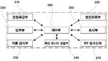
도 2를 참조하면, 본 발명에 따른 차량 안테나(130)는 전원 공급부(210), 입력부(220), 카콜 감지부(230), 메인 유니트 결합부(240), 발진 회로부(250), 표시부(260), RF 송수신부(270) 및 제어부(280)를 포함한다.Referring to FIG. 2, the
전원 공급부(210)는 차량 안테나(130)에 전원을 공급하는 기능을 수행한다. 전원 공급부(210)는 차량(110) 내의 전원(예를 들어, 배터리 등) 또는 자체 전원(예를 들어, 건전지, 충전지 등)으로부터 전원을 제공받을 수 있다. 또한, 차량(110)이 주행 중인 경우와 주차 중인 경우를 구분하여 선택적으로 전원을 제공받을 수도 있다.The
입력부(220)는 사용자가 원하는 차량 상태 정보(예를 들어, 차량 온도, 자체 전원의 잔존량 등)를 표시하도록 하거나 차량 상태 설정 정보(예를 들어, 카콜 센서의 감도, 현재 시각 설정, 온도 표시 방법 등)를 변경하도록 하기 위한 하나 이상의 버튼을 포함한다. 입력부(220)에 포함된 버튼의 용도에 대해서는 이후 관련 도면을 참조하여 상세히 설명한다.The
카콜 감지부(230)는 카콜 LED부, 카콜 감도 조절부, 센서부를 포함한다. 본 발명에 따른 차량 안테나(130)에서 수행할 수 있는 카콜 기능은 차량(110)에 미리 지정된 크기 이상의 충격이 발생한 경우 차량 정보를 메인 유니트(140)를 이용하여 사용자에게 통지함과 동시에 차량(110)의 스피커를 통해 경고음을 발생시키는 기능(즉, 도난 방지 기능)이다. 카콜 LED부는 점멸 상태에서 문 열림(도난) 또는 충격 감지 상태임을 표시한다. 또한 카콜 LED부는 미리 지정된 크기 이상의 충격이 센서부에 의해 감지된 경우 점멸에 의해 경고를 수행한다. 물론 카콜 LED부는 별도로 구비되지 않고 표시부(260)에 포함될 수 있다. 카콜 감도 조절부는 카콜 기능을 수행함에 있어 사용자가 민감도를 조절할 수 있도록 하는 수단이다. 예를 들어 카콜 감도 조절부는 "LOW"와 "HIGH"의 두 가지 선택 모드를 포함할 수 있다. 센서부는 차량(110)에 전달되는 충격 또는 문 열림을 감지하는 수단이다. 센서부는 미리 지정된 크기 이상의 충격 또는 문 열림이 감지된 경우 감지 신호를 제어부(280)로 전달하여 원격 제어기(120)로 해당 정보가 전송되도록 함과 동시에 카콜 LED부 또는 표시부(260)를 통해 알람이 수행되도록 한다. 또한, 메인 유니트(140)에 결합된 스피커 등을 통해 경고음이 출력될 수도 있다. 물론, 센서부는 충격 또는 문 열림 여부를 감지하여 제어부(280)로 해당 정보를 전송하면, 제어부(280)가 해당 충격의 크기가 미리 지정된 크기 이상인지 여부를 판단하여 도난 방지 기능(예를 들어, 경고음 출력, 차주 호출 등)을 수행할 수도 있다.The
메인 유니트 결합부(240)는 차량 안테나(130)가 차량(110)에 구비된 메인 유니트(140)와 유선(또는 무선)으로 결합되도록 하는 수단이다. 즉, 원격 제어기(120)로부터 수신되는 제어 신호를 메인 유니트(140)로 전달하고, 메인 유니트(140)로부터 동작 결과 정보를 전달받는 기능을 수행한다.The main
발진 회로부(250)는 제어부(280)의 동작을 위해 필요한 교류 전류를 발생시키는 장치이다. 즉, 발진 회로부(250)는 특정한 주파수의 전류만이 회로에 흐르도 록 한다.The
표시부(260)는 사용자가 차량(110)의 상태를 외부에서 시각적으로 인식할 수 있도록 차량 상태 정보를 표시하는 기능을 수행한다. 표시부(260)에 표시될 수 있는 차량 상태 정보에는 차량 내부의 온도, 차량의 건전지 전압, 엔진 동작 여부 등의 정보가 포함될 수 있다. 또한, 원격 제어기(120)로부터 수신된 차량 제어 신호에 상응하는 선택 데이터(예를 들어, 원격 시동, 에어컨 시동, 헤드라이트 온 등) 및 동작 결과 정보 등도 제어부(280)의 제어에 의해 표시부(260)에 표시된다.The
RF 송수신부(270)는 원격 제어기(120)로부터 차량 제어 신호를 수신하여 제어부(280)로 당해 차량 제어 신호를 전달하고, 제어부(280)의 제어에 의해 동작 결과 정보를 원격 제어기(120)로 전송하는 기능을 수행한다.The
제어부(280)는 차량 제어 신호 및 동작 결과 정보의 송수신, 입력부(220)를 통한 사용자 명령에 따른 차량 상태 정보 표시 등을 위해 차량 안테나(130)를 제어하는 기능을 수행한다. 제어부(280)는 차량 상태 정보를 표시부(260)에 표시하기 위하여 필요한 경우 메인 유니트(140) 또는 메인 유니트(140)와 결합된 센서로부터 메인 유니트 결합부(240)를 통해 관련 정보를 수신할 수 있다. 또한 제어부(280)는 차량 제어 신호 또는 입력부(220)를 통해 차량 상태 설정 정보의 변경 요청이 입력된 경우 당해 변경 요청에 상응하도록 차량 상태 설정 정보를 변경하고 변경된 차량 상태 설정 정보를 메인 유니트(140)로 전달하는 기능을 수행한다.The
도 2에는 도시되지 않았으나, 차량 안테나(130)는 변경된 차량 상태 설정 정보, 차량(110)의 긴급 사항, 차량 운행 기록 등을 저장하기 위한 저장부를 더 포 함할 수 있다. 예를 들어, 차량(110)이 원격 제어기(120)에 차량의 긴급 사항을 전달하기 어려운 위치에 있는 경우 해당 정보가 추후 원격 제어기(120)나 표시부(260)를 통해 표시될 수 있다. 또한, 사용자는 차량 안테나(130)의 저장부에 저장된 차량 운행 기록을 이용하여 전자식 차계부로도 활용될 수 있다.Although not shown in FIG. 2, the
또한, 차량 안테나는 원격 제어기(120)로부터 수신된 차량 제어 신호, 입력부(220)를 통해 입력된 사용자 명령에 상응하는 차량 상태 정보 또는 차량 상태 설정 정보를 효과음 또는 음성 신호로 변환하여 출력하는 데이터 변환부와 스피커부를 더 포함할 수 있다.
In addition, the vehicle antenna converts the vehicle control signal received from the
도 3a 및 도 3b는 본 발명의 바람직한 일 실시예에 따른 차량 안테나의 동작 과정을 나타낸 순서도이고, 도 4는 본 발명의 바람직한 일 실시예에 따른 차량 안테나의 정면도이다.3A and 3B are flowcharts illustrating an operation process of a vehicle antenna according to an exemplary embodiment of the present invention, and FIG. 4 is a front view of the vehicle antenna according to an exemplary embodiment of the present invention.
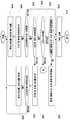
도 3a를 참조하면, 단계 310에서 차량 안테나(130)는 동작 개시된다. 본 발명에 따른 차량 안테나(130)는 차량의 전원 또는 자체 전원으로부터 전원이 유입되는 동안 지속적으로 미리 지정된 동작(예를 들어, 안테나 기능, 차량 상태 표시 기능, 카콜 기능 등)을 수행한다.Referring to FIG. 3A, the
단계 315에서 차량 안테나(130)는 사용자에 의해 입력부(220)를 통해 차량 상태 설정 또는 표시 명령이 입력되는지 여부를 판단한다. 차량 상태 설정 또는 표시 명령이 입력되는 경우에는 단계 320으로 진행하여 차량 상태 설정 또는 표시 동작을 수행하고 단계 315로 진행한다.In
사용자가 입력부(220)를 이용하여 차량 상태 설정 또는 표시 명령을 입력한 경우 표시부(260)에 관련 정보가 표시되는 상태를 도 4를 이용하여 간략히 설명한다. 물론 하기의 설명은 본 발명에 따른 차량 안테나(130)의 기능을 예시한 것에 지나지 않는다.When a user inputs a vehicle state setting or display command using the
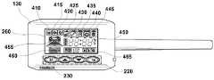
도 4에 도시된 차량 안테나(130)의 정면도를 참조하면, 차량 안테나(130)는 입력부(220), 카콜 감지부(230)의 카콜 감도 조절부, 표시부(260)를 포함한다.Referring to the front view of the
표시부(260)는 복수의 아이콘, 숫자 및 이미지 등을 이용하여 차량 상태 정보를 사용자에게 표시하기 위한 수단이다. 표시부(260)에는 카콜 기능 수행 아이콘(410), 차체 충격 감지 아이콘(415), 차주 호출 아이콘(420), 차량 제어 신호 수신에 따른 동작시 소리 출력 아이콘(425), 기능 정지 표시 아이콘(430), 엔진 시동 상태 유지 아이콘(435), 자동 문 잠금 아이콘(440), 자동 문 열림/잠금 아이콘(445), 숫자 정보 표시 영역(450), 엔진 시동 상태 표시 영역(455), 배터리 잔량 표시 영역(460), 차량 설정 변경 영역(465) 등이 표시될 수 있다. 사용자는 표시부(260)에 표시되는 아이콘, 이미지 등을 통해 자신이 선택한 기능을 확인할 수 있다.The
숫자 정보 표시 영역(450)에는 차량(110)의 엔진 시동 후 경과 시간, 시동 차단후의 경과 시간, 차량 내부의 온도(즉, 섭씨 온도 또는 화씨 온도) 등이 표시된다.In the numeric
엔진 시동 상태 표시 영역(455)에는 도로 이미지의 움직임을 통해 엔진 동작 상태가 표시된다.The engine start
배터리 잔량 표시 영역(460)에는 메인 유니트(140)와 결합되어 있는 전압 센서를 이용하여 측정된 차량(110)의 배터리 전압이 표시된다.In the battery remaining
입력부(220)는 복수의 키 버튼을 포함하며, 각각의 키 버튼마다 독립된 동작을 수행할 수 있도록 구성된다. 사용자는 입력부(220)에 포함된 키 버튼을 이용하여 옵션 설정 모드(즉, 메인 유니트(140)의 설정 변경 모드)로의 전환, 차량 상태 확인, 차량의 주행 시간 확인 등이 가능하다.The
사용자가 제1 버튼을 누른 경우 메인 유니트(140)와 결합된 온도 센서에 의해 측정된 차량 온도가 숫자 정보 표시 영역(450)에 표시된다. 당해 차량 온도는 사용자의 선택에 의해 섭씨 또는 화씨 단위로 표시된다.When the user presses the first button, the vehicle temperature measured by the temperature sensor coupled with the
사용자가 제2 버튼을 누른 경우 표시부(260)의 백 라이트가 켜지도록 할 수 있다. 물론 미리 지정된 시간 경과후 백 라이트는 자동으로 꺼진다.When the user presses the second button, the backlight of the
사용자가 제3 버튼을 누른 경우 차량 상태 설정이 가능한 상태(즉, 옵션 모드)로 전환된다. 이때 사용자가 제1 버튼, 제2 버튼을 이용하여 설정을 원하는 항목을 선택하여 변경할 수 있다. 또한, 차량 상태 설정이 완료된 후 제4 버튼을 누르면 갱신된 차량 상태 정보가 메인 유니트(140)로 전달되며, 차량 안테나(130)는 수신 기능 상태로 전환된다.When the user presses the third button, the vehicle state can be set (ie, option mode). In this case, the user may select and change an item to be set using the first button and the second button. In addition, when the fourth button is pressed after the vehicle state setting is completed, the updated vehicle state information is transmitted to the
다시 도 3a를 참조하면, 단계 325에서 차량 안테나(130)는 원격 제어기(120) 또는 메인 유니트(140)로부터 데이터(예를 들어, 차량 제어 신호, 동작 결과 정보 등)가 수신되는지 여부를 판단한다. 데이터가 수신되면 단계 330으로 진행하고, 그렇지 않으면 단계 360(도 3b 참조)으로 진행한다.Referring back to FIG. 3A, in
단계 330에서 차량 안테나(130)는 수신된 데이터가 원격 제어 신호(즉, 원격 제어기(120)로부터 수신된 차량 제어 신호)인지 여부를 판단한다. 원격 제어 신호인 경우 단계 335에서 차량 안테나(130)는 원격 제어 신호와 함께 수신된 원격 제어기(120)의 코드 번호가 유효한지 여부를 검사한다. 코드 번호가 유효하지 않은 경우 단계 315로 진행한다. 코드 번호가 유효한 경우 단계 340에서 차량 안테나(130)는 수신된 제어 신호를 분석하여 제어 신호에 상응하도록 차량 상태 설정 정보를 갱신하여 표시부(260)에 표시한다. 차량 안테나(130)는 원격 제어기(120)로부터 수신된 제어 신호를 이용하여 차량 상태 설정 정보를 갱신하는 방법은 입력부(220)를 통해 입력된 사용자 명령에 따라 차량 상태 설정 정보를 갱신하는 방법과 유사하므로 이에 대한 설명은 생략한다.In
단계 345에서 차량 안테나(130)는 원격 제어기(120)로부터 수신된 제어 신호에 상응하여 갱신된 차량 상태 설정 정보를 메인 유니트(140)로 전달한다. 이후 차량 안테나(130)는 단계 315로 다시 진행하거나 단계를 종료한다.In
다시 단계 330을 참조하면, 단계 325를 통해 수신된 데이터가 원격 제어 신호가 아닌 경우(즉, 메인 유니트(140)로부터 수신되는 동작 결과 정보, 차주 호출 신호 등인 경우) 단계 340으로 진행한다.Referring back to step 330, if the data received in
차량 안테나(130)는 단계 340에서 수신 데이터 분석 및 표시 작업을 수행한다. 단계 345에서 차량 안테나(130)는 단계 325를 통해 수신한 데이터가 원격 제어기(120)로 전송할 필요가 있는지 여부를 판단한다. 원격 제어기(120)로 전송할 필요가 있는 경우 단계 355로 진행하여 해당 정보를 전송한다. 이후 차량 안테나는 단계 315로 다시 진행하거나 단계를 종료한다.The
도 3b를 참조하면, 단계 360에서 차량 안테나(130)는 카콜 기능의 수행 여부를 판단한다. 예를 들어, 차량의 주차 완료 및 시동 정지된 경우 차량 안테나(130)는 안테나 기능과 동시에 카콜 기능을 수행할 수 있다.Referring to FIG. 3B, in
카콜 기능이 수행되는 경우 차량 안테나(130)(즉, 차량 안테나(130)의 카콜 감지부(230))는 차량 표면에 이상 징후(예를 들어, 충격, 진동 등)가 발생하였는지 여부를 판단한다. 이상 징후가 발생하지 않은 경우에는 단계 360(또는 단계 315)으로 진행하고, 그렇지 않은 경우에는 카콜 기능(예를 들어, 경보음 발생, 차주 호출 등)을 수행한다. 이후 차량 안테나(130)는 단계 360(또는 단계 315)으로 다시 진행하거나 단계를 종료한다.When the car call function is performed, the vehicle antenna 130 (that is, the car
반면에, 카콜 기능이 수행되지 않은 상태라면 차량 안테나(130)는 기타 기능(예를 들어, 백 라이트 동작, 주행시간 초기화 등)의 수행 명령이 입력되는지 여부를 판단한다. 기타 기능의 수행 명령이 입력되는 경우에는 단계 380으로 진행하여 해당 기능을 수행한다. 이후 차량 안테나(130)는 단계 315로 다시 진행하거나 단계를 종료한다.
On the other hand, when the car call function is not performed, the
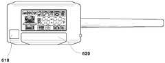
도 5는 본 발명의 바람직한 다른 실시예에 따른 차량 안테나의 블록 구성도이고, 도 6은 본 발명의 바람직한 다른 실시예에 따른 차량 안테나의 정면도이다.5 is a block diagram of a vehicle antenna according to another preferred embodiment of the present invention, Figure 6 is a front view of a vehicle antenna according to another preferred embodiment of the present invention.
본 발명에 따른 차량 안테나(130)는 차량 내부의 미리 지정된 지점(예를 들어, 대시보드 상단)에 부착되거나 차량 외부의 미리 지정된 지점(예를 들어, A필 러)에 부착될 수 있다. 즉, 본 발명에 따른 차량 안테나(130)의 부착 위치는 외부에서 사용자가 차량 안테나(130)의 표시부(260)에 표시되는 차량 상태 정보를 확인할 수 있는 위치이면 아무런 제한이 없다.The
그러나, 차량 안테나(130) 차량 외부에 부착되는 경우 제3자가 입력부(220)의 키 버튼을 마구 누르는 경우가 있을 수 있다. 따라서, 지정된 사용자만이 입력부(220)의 조작이 가능하도록 입력부(220)의 키 버튼을 감추어둘 필요가 있다.However, when the
도 5 및 도 6을 참조하면, 본 발명에 따른 차량 안테나(130)는 전원 공급부(210), 입력부(220), 카콜 감지부(230), 메인 유니트 결합부(240), 발진 회로부(250), 표시부(260), RF 송수신부(270), 제어부(280) 및 사용자 인식부(510)를 포함한다.5 and 6, the
사용자 인식부(510)는 지문 입력부(610), 지문 인식부(도시되지 않음), 키 버튼 커버부(620)를 포함한다. 도 6에 도시된 바와 같이 입력부(220)의 키 버튼들과 카콜 감지부(230)의 카콜 감도 조절부는 키 버튼 커버부(620)에 의해 임시로 가려진다.The
사용자가 지문 입력부(610)에 자신의 손가락을 대면 사용자의 지문이 입력되어 지문 인식부로 전달된다. 지문 입력부(220)를 통해 사용자의 지문이 입력되는 방법은 공지의 방법이므로 이에 대한 설명은 생략한다.When the user touches his or her finger on the
지문 인식부는 지문 입력부(220)를 통해 입력된 사용자의 지문과 저장부(도시되지 않음)에 이미 지정되어 있는 사용자의 지문이 일치하는지 여부를 검사한다. 만일 양 지문이 일치한다면 제어부(280)로 해당 정보를 전송하고, 제어부(280)는 키 버튼 커버부(620)를 오픈시켜 입력부(220)의 키 버튼이 노출되도록 한다.The fingerprint recognition unit checks whether the fingerprint of the user input through the
물론, 당해 차량 안테나(130)가 차량 외부에 부착되는 경우라면 당해 차량 안테나(130)에 방수 처리가 되어져야 함은 당연하다.Of course, if the
본 발명은 상기 실시예에 한정되지 않으며, 많은 변형이 본 발명의 사상 내에서 당 분야에서 통상의 지식을 가진 자에 의하여 가능함은 물론이다.
The present invention is not limited to the above embodiments, and many variations are possible by those skilled in the art within the spirit of the present invention.
상술한 바와 같이 본 발명에 따른 자동차의 원격 시동을 위한 안테나 모듈은 메인 유니트의 기능 설정 변경 기능 및 차량 정보 등의 표시 기능을 부가함으로써 사용자에게 편의성을 제공할 수 있다.As described above, the antenna module for remotely starting the vehicle according to the present invention may provide convenience to the user by adding a function setting change function of the main unit and a display function such as vehicle information.
또한 본 발명에 따른 자동차의 원격 시동을 위한 안테나 모듈은 메인 유니트에 추가적으로 설정할 수 있는 모듈 장비(예를 들어, 카콜 수행 장치 등)를 차량 안테나와 결합함으로써 원가 절감 및 구매 효과의 최대화를 도모할 수 있다.In addition, the antenna module for remote starting of the vehicle according to the present invention can maximize the cost reduction and the purchase effect by combining the module equipment (for example, a car call performance device, etc.) that can be additionally set in the main unit with the vehicle antenna. have.
Claims (14)
Translated fromKoreanPriority Applications (3)
| Application Number | Priority Date | Filing Date | Title |
|---|---|---|---|
| KR1020030057806AKR100544332B1 (en) | 2003-08-21 | 2003-08-21 | Method of displaying vehicle information using antenna module and antenna module for remote start of car |
| CN2004800239642ACN1839656B (en) | 2003-08-21 | 2004-08-11 | Antenna module for remote engine starting of vehicle and method for displaying vehicle information using the antenna module |
| PCT/KR2004/002015WO2005020622A1 (en) | 2003-08-21 | 2004-08-11 | Antenna module for remote engine starting of vehicle and method for displaying vehicle information using the antenna module |
Applications Claiming Priority (1)
| Application Number | Priority Date | Filing Date | Title |
|---|---|---|---|
| KR1020030057806AKR100544332B1 (en) | 2003-08-21 | 2003-08-21 | Method of displaying vehicle information using antenna module and antenna module for remote start of car |
Related Child Applications (1)
| Application Number | Title | Priority Date | Filing Date |
|---|---|---|---|
| KR20-2003-0028150UDivisionKR200335175Y1 (en) | 2003-09-02 | 2003-09-02 | Antenna module for remote engine starting of vehicle |
Publications (2)
| Publication Number | Publication Date |
|---|---|
| KR20030072293A KR20030072293A (en) | 2003-09-13 |
| KR100544332B1true KR100544332B1 (en) | 2006-01-23 |
Family
ID=32227669
Family Applications (1)
| Application Number | Title | Priority Date | Filing Date |
|---|---|---|---|
| KR1020030057806AExpired - Fee RelatedKR100544332B1 (en) | 2003-08-21 | 2003-08-21 | Method of displaying vehicle information using antenna module and antenna module for remote start of car |
Country Status (3)
| Country | Link |
|---|---|
| KR (1) | KR100544332B1 (en) |
| CN (1) | CN1839656B (en) |
| WO (1) | WO2005020622A1 (en) |
Cited By (1)
| Publication number | Priority date | Publication date | Assignee | Title |
|---|---|---|---|---|
| KR20160117811A (en)* | 2015-03-31 | 2016-10-11 | 한국전자통신연구원 | Vehicle network system and protocol communication method thereof |
Families Citing this family (5)
| Publication number | Priority date | Publication date | Assignee | Title |
|---|---|---|---|---|
| MX2012002753A (en)* | 2009-09-03 | 2012-08-03 | Fisher Controls Int | Emergency test control panel device, system and method. |
| CN103770742B (en)* | 2012-10-26 | 2015-09-02 | 广州汽车集团股份有限公司 | A kind of method of remote control vehicle |
| CN104129359B (en)* | 2014-07-15 | 2017-11-14 | 丽水市知科科技有限公司 | A kind of vehicle remote controls open-door system |
| CN106467084B (en)* | 2015-08-20 | 2019-03-12 | 北京宝沃汽车有限公司 | The anti-thefting monitoring method and apparatus of vehicle and vehicle |
| US10249182B1 (en) | 2018-01-04 | 2019-04-02 | Directed, Llc | Remote vehicle system configuration, control, and telematics |
Family Cites Families (5)
| Publication number | Priority date | Publication date | Assignee | Title |
|---|---|---|---|---|
| JPH07246915A (en)* | 1994-03-10 | 1995-09-26 | Alpine Electron Inc | On-vehicle receiving device |
| KR19990048233A (en)* | 1997-12-09 | 1999-07-05 | 유기범 | Remote starter with caller calling function and method |
| US6150926A (en)* | 1998-03-05 | 2000-11-21 | Flick; Kenneth E. | Vehicle security system including indicator mounted to window antenna unit and related methods |
| US20020190872A1 (en)* | 2001-06-18 | 2002-12-19 | Johnson Controls Technology Company. | Trainable receiver for remote control of a vehicle actuator |
| CN1219265C (en)* | 2001-12-07 | 2005-09-14 | 卢嘉冰 | Electronic intelligent comprehensive management system and method for preventing theft and rubbing of motor vehicle |
- 2003
- 2003-08-21KRKR1020030057806Apatent/KR100544332B1/ennot_activeExpired - Fee Related
- 2004
- 2004-08-11CNCN2004800239642Apatent/CN1839656B/ennot_activeExpired - Fee Related
- 2004-08-11WOPCT/KR2004/002015patent/WO2005020622A1/enactiveApplication Filing
Cited By (2)
| Publication number | Priority date | Publication date | Assignee | Title |
|---|---|---|---|---|
| KR20160117811A (en)* | 2015-03-31 | 2016-10-11 | 한국전자통신연구원 | Vehicle network system and protocol communication method thereof |
| KR102286575B1 (en)* | 2015-03-31 | 2021-08-09 | 한국전자통신연구원 | Vehicle network system and protocol communication method thereof |
Also Published As
| Publication number | Publication date |
|---|---|
| CN1839656A (en) | 2006-09-27 |
| CN1839656B (en) | 2010-10-20 |
| KR20030072293A (en) | 2003-09-13 |
| WO2005020622A1 (en) | 2005-03-03 |
Similar Documents
| Publication | Publication Date | Title |
|---|---|---|
| US11580802B2 (en) | Scheme for setting/using electronic device as keyless device of vehicle and adjusting devices in the vehicle | |
| US6100792A (en) | Car security apparatus and car security system | |
| EP2668546B1 (en) | Wireless trainable transceiver device with integrated interface and gps modules | |
| US8209093B2 (en) | Adaptive instruction system for a vehicle | |
| JP2020079542A (en) | Methods for locking and/or unlocking electric vehicle and associated apparatus | |
| EP3330940B1 (en) | Systems and methods for an enhanced garage door opener remote control | |
| EP2535209A1 (en) | Tire pressure monitoring system and onboard tire pressure device thereof | |
| WO2000069691A1 (en) | Emergency call system with theft prevention function | |
| KR100680083B1 (en) | A portable device for the electronic key system and a system for reminding the user to carry the portable device | |
| US20040049325A1 (en) | Vehicle control system with selectable vehicle style image and associated methods | |
| KR20190050002A (en) | Remote control device and vehicle including the same | |
| KR100544332B1 (en) | Method of displaying vehicle information using antenna module and antenna module for remote start of car | |
| JP2006318108A (en) | Warning device | |
| KR200335175Y1 (en) | Antenna module for remote engine starting of vehicle | |
| KR20090016775A (en) | Anti-theft device using GPS function | |
| JP3800229B2 (en) | Detection device, abnormality monitoring system, control program for detection device, and recording medium recording control program for detection device | |
| JP2002318684A (en) | Information system for supplying functional element or explanatory information regarding control, etc., in automobile | |
| JP3453479B2 (en) | Car security device and car security system | |
| JP5126328B2 (en) | Alerting device, alerting method, remote control system | |
| KR100440329B1 (en) | Vehicle position detecting device and method thereof | |
| KR200225966Y1 (en) | Two-way remote start and burglar alarm device for vehicles | |
| KR200233679Y1 (en) | GPS and CDMA based vehicle alarm, remote engine starter system | |
| KR100548405B1 (en) | Vehicle remote control system using mobile communication terminal | |
| KR100243884B1 (en) | Car burglar alarm | |
| JP7065534B2 (en) | Remote controllers and systems for in-vehicle devices |
Legal Events
| Date | Code | Title | Description |
|---|---|---|---|
| A201 | Request for examination | ||
| PA0109 | Patent application | St.27 status event code:A-0-1-A10-A12-nap-PA0109 | |
| PA0201 | Request for examination | St.27 status event code:A-1-2-D10-D11-exm-PA0201 | |
| PG1501 | Laying open of application | St.27 status event code:A-1-1-Q10-Q12-nap-PG1501 | |
| E902 | Notification of reason for refusal | ||
| PE0902 | Notice of grounds for rejection | St.27 status event code:A-1-2-D10-D21-exm-PE0902 | |
| P11-X000 | Amendment of application requested | St.27 status event code:A-2-2-P10-P11-nap-X000 | |
| P13-X000 | Application amended | St.27 status event code:A-2-2-P10-P13-nap-X000 | |
| E701 | Decision to grant or registration of patent right | ||
| PE0701 | Decision of registration | St.27 status event code:A-1-2-D10-D22-exm-PE0701 | |
| R18-X000 | Changes to party contact information recorded | St.27 status event code:A-3-3-R10-R18-oth-X000 | |
| GRNT | Written decision to grant | ||
| PR0701 | Registration of establishment | St.27 status event code:A-2-4-F10-F11-exm-PR0701 | |
| PR1002 | Payment of registration fee | St.27 status event code:A-2-2-U10-U11-oth-PR1002 Fee payment year number:1 | |
| PG1601 | Publication of registration | St.27 status event code:A-4-4-Q10-Q13-nap-PG1601 | |
| PN2301 | Change of applicant | St.27 status event code:A-5-5-R10-R11-asn-PN2301 | |
| PN2301 | Change of applicant | St.27 status event code:A-5-5-R10-R14-asn-PN2301 | |
| PR1001 | Payment of annual fee | St.27 status event code:A-4-4-U10-U11-oth-PR1001 Fee payment year number:4 | |
| PR1001 | Payment of annual fee | St.27 status event code:A-4-4-U10-U11-oth-PR1001 Fee payment year number:5 | |
| PR1001 | Payment of annual fee | St.27 status event code:A-4-4-U10-U11-oth-PR1001 Fee payment year number:6 | |
| PR1001 | Payment of annual fee | St.27 status event code:A-4-4-U10-U11-oth-PR1001 Fee payment year number:7 | |
| FPAY | Annual fee payment | Payment date:20130114 Year of fee payment:8 | |
| PR1001 | Payment of annual fee | St.27 status event code:A-4-4-U10-U11-oth-PR1001 Fee payment year number:8 | |
| FPAY | Annual fee payment | Payment date:20140107 Year of fee payment:9 | |
| PR1001 | Payment of annual fee | St.27 status event code:A-4-4-U10-U11-oth-PR1001 Fee payment year number:9 | |
| FPAY | Annual fee payment | Payment date:20150112 Year of fee payment:10 | |
| PR1001 | Payment of annual fee | St.27 status event code:A-4-4-U10-U11-oth-PR1001 Fee payment year number:10 | |
| FPAY | Annual fee payment | Payment date:20160111 Year of fee payment:11 | |
| PR1001 | Payment of annual fee | St.27 status event code:A-4-4-U10-U11-oth-PR1001 Fee payment year number:11 | |
| FPAY | Annual fee payment | Payment date:20170109 Year of fee payment:12 | |
| PR1001 | Payment of annual fee | St.27 status event code:A-4-4-U10-U11-oth-PR1001 Fee payment year number:12 | |
| LAPS | Lapse due to unpaid annual fee | ||
| PC1903 | Unpaid annual fee | St.27 status event code:A-4-4-U10-U13-oth-PC1903 Not in force date:20180112 Payment event data comment text:Termination Category : DEFAULT_OF_REGISTRATION_FEE | |
| PC1903 | Unpaid annual fee | St.27 status event code:N-4-6-H10-H13-oth-PC1903 Ip right cessation event data comment text:Termination Category : DEFAULT_OF_REGISTRATION_FEE Not in force date:20180112 |