KR100543160B1 - Surface moving friction welding method for thin plate welding - Google Patents
Surface moving friction welding method for thin plate weldingDownload PDFInfo
- Publication number
- KR100543160B1 KR100543160B1KR1020030068113AKR20030068113AKR100543160B1KR 100543160 B1KR100543160 B1KR 100543160B1KR 1020030068113 AKR1020030068113 AKR 1020030068113AKR 20030068113 AKR20030068113 AKR 20030068113AKR 100543160 B1KR100543160 B1KR 100543160B1
- Authority
- KR
- South Korea
- Prior art keywords
- joining
- welding
- probe
- joining members
- welding method
- Prior art date
- Legal status (The legal status is an assumption and is not a legal conclusion. Google has not performed a legal analysis and makes no representation as to the accuracy of the status listed.)
- Expired - Fee Related
Links
Images


Classifications
- B—PERFORMING OPERATIONS; TRANSPORTING
- B23—MACHINE TOOLS; METAL-WORKING NOT OTHERWISE PROVIDED FOR
- B23K—SOLDERING OR UNSOLDERING; WELDING; CLADDING OR PLATING BY SOLDERING OR WELDING; CUTTING BY APPLYING HEAT LOCALLY, e.g. FLAME CUTTING; WORKING BY LASER BEAM
- B23K20/00—Non-electric welding by applying impact or other pressure, with or without the application of heat, e.g. cladding or plating
- B23K20/12—Non-electric welding by applying impact or other pressure, with or without the application of heat, e.g. cladding or plating the heat being generated by friction; Friction welding
- B—PERFORMING OPERATIONS; TRANSPORTING
- B23—MACHINE TOOLS; METAL-WORKING NOT OTHERWISE PROVIDED FOR
- B23K—SOLDERING OR UNSOLDERING; WELDING; CLADDING OR PLATING BY SOLDERING OR WELDING; CUTTING BY APPLYING HEAT LOCALLY, e.g. FLAME CUTTING; WORKING BY LASER BEAM
- B23K20/00—Non-electric welding by applying impact or other pressure, with or without the application of heat, e.g. cladding or plating
- B23K20/22—Non-electric welding by applying impact or other pressure, with or without the application of heat, e.g. cladding or plating taking account of the properties of the materials to be welded
- B23K20/233—Non-electric welding by applying impact or other pressure, with or without the application of heat, e.g. cladding or plating taking account of the properties of the materials to be welded without ferrous layer
- B23K20/2336—Non-electric welding by applying impact or other pressure, with or without the application of heat, e.g. cladding or plating taking account of the properties of the materials to be welded without ferrous layer both layers being aluminium
- B—PERFORMING OPERATIONS; TRANSPORTING
- B23—MACHINE TOOLS; METAL-WORKING NOT OTHERWISE PROVIDED FOR
- B23K—SOLDERING OR UNSOLDERING; WELDING; CLADDING OR PLATING BY SOLDERING OR WELDING; CUTTING BY APPLYING HEAT LOCALLY, e.g. FLAME CUTTING; WORKING BY LASER BEAM
- B23K20/00—Non-electric welding by applying impact or other pressure, with or without the application of heat, e.g. cladding or plating
- B23K20/12—Non-electric welding by applying impact or other pressure, with or without the application of heat, e.g. cladding or plating the heat being generated by friction; Friction welding
- B23K20/122—Non-electric welding by applying impact or other pressure, with or without the application of heat, e.g. cladding or plating the heat being generated by friction; Friction welding using a non-consumable tool, e.g. friction stir welding
- B—PERFORMING OPERATIONS; TRANSPORTING
- B23—MACHINE TOOLS; METAL-WORKING NOT OTHERWISE PROVIDED FOR
- B23K—SOLDERING OR UNSOLDERING; WELDING; CLADDING OR PLATING BY SOLDERING OR WELDING; CUTTING BY APPLYING HEAT LOCALLY, e.g. FLAME CUTTING; WORKING BY LASER BEAM
- B23K2101/00—Articles made by soldering, welding or cutting
- B23K2101/04—Tubular or hollow articles
- B23K2101/06—Tubes
- B23K2101/08—Tubes finned or ribbed
- B—PERFORMING OPERATIONS; TRANSPORTING
- B23—MACHINE TOOLS; METAL-WORKING NOT OTHERWISE PROVIDED FOR
- B23K—SOLDERING OR UNSOLDERING; WELDING; CLADDING OR PLATING BY SOLDERING OR WELDING; CUTTING BY APPLYING HEAT LOCALLY, e.g. FLAME CUTTING; WORKING BY LASER BEAM
- B23K2103/00—Materials to be soldered, welded or cut
- B23K2103/08—Non-ferrous metals or alloys
- B23K2103/10—Aluminium or alloys thereof
- B—PERFORMING OPERATIONS; TRANSPORTING
- B23—MACHINE TOOLS; METAL-WORKING NOT OTHERWISE PROVIDED FOR
- B23K—SOLDERING OR UNSOLDERING; WELDING; CLADDING OR PLATING BY SOLDERING OR WELDING; CUTTING BY APPLYING HEAT LOCALLY, e.g. FLAME CUTTING; WORKING BY LASER BEAM
- B23K2103/00—Materials to be soldered, welded or cut
- B23K2103/08—Non-ferrous metals or alloys
- B23K2103/12—Copper or alloys thereof
- B—PERFORMING OPERATIONS; TRANSPORTING
- B23—MACHINE TOOLS; METAL-WORKING NOT OTHERWISE PROVIDED FOR
- B23K—SOLDERING OR UNSOLDERING; WELDING; CLADDING OR PLATING BY SOLDERING OR WELDING; CUTTING BY APPLYING HEAT LOCALLY, e.g. FLAME CUTTING; WORKING BY LASER BEAM
- B23K2103/00—Materials to be soldered, welded or cut
- B23K2103/16—Composite materials, e.g. fibre reinforced
- B—PERFORMING OPERATIONS; TRANSPORTING
- B23—MACHINE TOOLS; METAL-WORKING NOT OTHERWISE PROVIDED FOR
- B23K—SOLDERING OR UNSOLDERING; WELDING; CLADDING OR PLATING BY SOLDERING OR WELDING; CUTTING BY APPLYING HEAT LOCALLY, e.g. FLAME CUTTING; WORKING BY LASER BEAM
- B23K2103/00—Materials to be soldered, welded or cut
- B23K2103/18—Dissimilar materials
Landscapes
- Engineering & Computer Science (AREA)
- Mechanical Engineering (AREA)
- Pressure Welding/Diffusion-Bonding (AREA)
Abstract
Translated fromKoreanDescription
Translated fromKorean도1은 본 발명의 용접장치 및 공정의 개략도,1 is a schematic view of a welding apparatus and process of the present invention;
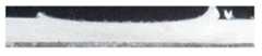
도2는 두께 0.9mm인 6061 알루미늄 합금 판재의 용접 후 단면 사진,2 is a cross-sectional photograph after welding of a 6061 aluminum alloy sheet having a thickness of 0.9 mm,
도3은 두께 1.0mm인 1010 알루미늄 합금 판재의 용접 후 단면 사진,3 is a cross-sectional photograph after welding of a 1010 aluminum alloy sheet having a thickness of 1.0 mm,
도4는 두께 0.9mm인 6061 알루미늄 합금 판재 및 구리 판재의 이종재료 판재간의 용접 후 단면 사진.Figure 4 is a cross-sectional photograph after welding between the dissimilar material plate of 6061 aluminum alloy plate and copper plate of 0.9mm thickness.
* 도면중 주요부분에 대한 부호의 설명 *Explanation of symbols on the main parts of the drawings
1,2 : 접합부재 3 : 프로브1,2: joining member 3: probe
4 : 용접부 5 : 접합요구선4
6 : 소성영역6: firing area
본 발명은 금속박판간을 용접결함의 발생이 없이 양호한 품질로 연속 맞대기용접할 수 있는 박판 접합용 표면이동 마찰용접방법에 관한 것이다.The present invention relates to a surface-moving friction welding method for thin plate joining, which is capable of continuous butt welding with good quality without the occurrence of welding defects.
용접하고자 하는 부재를 대상으로 마찰원리를 근간으로 하여 적당량의 열을 발생시키고, 마찰부와 인접한 영역에 소성유동을 생성시켜 접합하는 마찰용접법은 지난 수 십년 간 사용되어 왔다. 이러한 용접방법은 일반적인 용융용접과 대비하여 고상용접이란 장점을 가진다. 통상의 마찰용접법에서 마찰열은 2개의 서로 결합될 부재에서만 발생하는 것이 일반적이다. 이러한 제약으로 인해 기존의 마찰용접법은 용접부재중 하나가 반드새 축대칭이어야 하며, 특정한 방향의 연속용접을 필요로 하는 구조물에는 사용할 수 없는 약점을 가진다.Friction welding methods have been used for several decades to produce a suitable amount of heat based on the friction principle of a member to be welded, and to generate and join plastic flow in the area adjacent to the friction part. This welding method has the advantage of solid phase welding as compared to the general melt welding. In a conventional friction welding method, friction heat generally occurs only in two members to be joined to each other. Due to these limitations, the conventional friction welding method requires that one of the welding members must be axisymmetric, and has a weakness that cannot be used in a structure requiring continuous welding in a specific direction.
상기의 마찰용접법을 개선한 방법으로 제3의 단단한 프로브(probe)와 프로브 핀(probe pin)을 도입한 마찰교반용접법(WO 93/10935, WO 95/26254)이 개발된 바 있다. 이 마찰교반용접의 원리는 접합부재 이음부의 맞대기면을 따라 특수한 나사산 형태의 돌기를 가지는 환봉 모양의 경질재료로 된 프로브 핀을 고속으로 회전시키면서 삽입하면 프로브 핀과 접합부재간의 상호마찰에 의해 열이 발생하고, 이 마찰열에 의해 주변의 소재가 열적으로 연화되면서 프로브 핀의 회전에 의한 강제적인 소성유동으로 혼합되어 접합이 이루어지게 되는 것이다. 이 마찰교반용접법은 알루미늄 합금, 마그네슘 합금, 티타늄 합금, 다이캐스팅 등으로 제조된 주조 제품, 금속기지 복합재료 등 기존 용융용접 기술의 적용이 거의 불가능했던 재료의 접합이 가능해지는 고상용접이라는 점과 함께 연속용접이 가능하다는 장점을 갖는다.As a method of improving the friction welding method, a friction stir welding method (WO 93/10935, WO 95/26254) incorporating a third rigid probe and a probe pin has been developed. The principle of this friction stir welding is that if the probe pin is made of a round rod-shaped hard material having a special thread-shaped protrusion along the butt face of the joint, it is rotated at high speed, and the friction between the probe pin and the joint member causes heat. This material is thermally softened by the frictional heat and mixed by a forced plastic flow due to the rotation of the probe pins. This friction stir welding method is a continuous phase welding process that enables the joining of materials that are almost impossible to apply existing melt welding techniques such as cast products made of aluminum alloys, magnesium alloys, titanium alloys, die castings, and metal base composites. It has the advantage that welding is possible.
그러나, 상기와 같은 종래의 마찰교반용접에서는 프로브 핀의 존재로 인해 지금까지 알려진 바로는 접합부재의 두께가 적어도 1.2mm 이상에서만 적용이 가능하고, 용접말단에서 프로브 핀의 삽입으로 인해 생기는 빈 공간을 채울 수 있는 재 료가 선단부에 더 이상 존재하지 않아서 용접결함이 유발되는 단점이 있다.However, in the conventional friction stir welding as described above, due to the presence of the probe pin, it is possible to apply only the thickness of the joining member to at least 1.2 mm or more, and the empty space caused by the insertion of the probe pin at the welding end. Fillable material is no longer present at the distal end, which leads to a weld defect.
기존의 용융용접법에 의해서는 1.2mm 이하의 박판접합이 가능하다. 그러나, 우수한 품질의 접합을 얻기 위해서는 작업자가 고도로 숙련되어야 하며 용가제, 분위기 가스, 별도의 열원 등이 반드시 필요하였다. 이러한 이유로 기존의 용융용접법에 의한 박판접합은 공정단가가 매우 높은 것이 단점이다. 그리고, 기존 용융용접법은 접합과정에서 인체에 유해한 자외선과 같은 광선과 퓸(fume), 분진 등이 다량으로 발생하여 작업자의 안전과 건강을 해치는 일이 많았으며, 작업장의 환경을 청결하게 유지하는 데에도 어려움이 많았다.By the conventional melt welding method, it is possible to join a thin plate of 1.2 mm or less. However, in order to obtain a good quality joint, the operator must be highly skilled, and a solvent, an atmosphere gas, and a separate heat source are necessary. For this reason, the thin plate bonding by the conventional melt welding method has a disadvantage that the process cost is very high. In the conventional melt welding method, a large amount of rays such as ultraviolet rays, fumes, dusts, etc., which are harmful to the human body are generated during the joining process, which often deteriorates worker safety and health. There were a lot of difficulties.
따라서, 본 발명은 이러한 배경에서 연구된 것으로, 두 개의 접합부재에 대한 맞대기 용접에 있어서 기존의 마찰교반용접법과는 달리 1.2mm 이하의 박판용접이 가능하고, 용접말단에 용접결함을 남기지 않고 연속용접이 가능한 박판접합용 표면이동 마찰용접방법을 제공하는 것을 그 목적으로 한다.Therefore, the present invention has been studied in the background, unlike the conventional friction stir welding in the butt welding of the two joining members, it is possible to weld a thin plate of less than 1.2mm, continuous welding without leaving a weld defect at the welding end It is an object of the present invention to provide such a surface moving friction welding method for thin plate joining.
상기의 목적을 달성하기 위한 본 발명은 두 개의 접합부재에 대한 맞대기 용접에 있어서, 프로브를 고속 회전시켜 마찰열을 발생시키면서 상기 접합부재의 표면에 강제적이고 극심한 소성변형을 야기시키고, 이러한 소성유동을 재료 내부까지 침투시켜 두 접합부재 간을 연속 맞대기 용접하는 것을 특징으로 하는 박판접합용 표면이동 마찰용접방법을 제공한다. 이하에서, 본 발명을 첨부도면을 참조하여 더욱 상세히 설명한다.The present invention for achieving the above object in the butt welding of the two joining members, the probe is rotated at high speed to generate a frictional heat, causing a forced and extreme plastic deformation on the surface of the joining member, and the plastic flow material The present invention provides a surface-moving friction welding method for thin plate joining, characterized by continuous penetration butt welding between two joining members. Hereinafter, the present invention will be described in more detail with reference to the accompanying drawings.
도1에서 보여진 바 같이, 본 발명에 따르면 두 개의 접합부재(1,2)의 맞대기 용접에 있어서 회전동력원에 결합된 환봉형 프로브(3)가 적절한 마찰열의 발생을 위해 접합부재(1,2)의 접합요구선(5)상에 일정한 압력으로 접해 고속 회전하면서 상기 두 접합부재(1,2)의 접합요구선(5)을 따라 수평이동을 하게 됨으로써 상기 두 접합부재(1,2)는 접합요구선(5)이 있는 맞대기부위를 따라 대략 프로브(3) 지름 크기의 너비를 가지는 용접부(4)가 형성되면서 접합된다. 상기 환봉형 프로브(3)의 회전으로 인해 발생한 소성영역(6)은 프로브(3) 직하 즉, 용접부재의 표면에서는 대략 프로브 하단의 면적과 같으나, 재료 내부로 갈수록 그 폭이 점차 줄어 든다. 이 소성영역(6)내에 존재하는 두 접합부재(1,2) 부위는 표면에서 발생한 마찰열과 소성변형에 의한 가공발열로 인해 연화되고, 강제적이고 극심한 소성유동으로 인해 접합된다.As shown in Fig. 1, according to the present invention, in the butt welding of the two joining
한편, 상술한 표면마찰에 의해 발생하는 소성영역(6)의 깊이는 접합부재(1,2)의 용접가능 두께를 결정하는 인자가 된다. 우선, 소성영역(6)의 깊이는 프로브(3)의 지름에 비례한다. 다음 (식1)은 용접가능 판재의 두께(t)와 프로브의 지름(D)과의 관계를 다양한 프로브 지름 조건에서의 실험결과로부터 얻은 결과이다.On the other hand, the depth of the

프로브(3)의 지름이 클수록 용접가능한 판재의 두께는 두꺼워지지만, 용접부(4)의 크기가 커지는 문제점이 따르게 된다. 또, 프로브(3)의 회전속도가 너 무 빠르면 마찰열이 심해져서 재료의 표면영역과 내부영역간의 온도편차가 크게 되어 재료의 연화가 표면에 집중되므로 소성영역의 내부 침투가 어려워지게 된다. 한편, 용접부재와 프로브간의 마찰계수가 크면 재료표면에 소성유동이 잘 발생하여 소성영역의 깊이가 깊어진다. 따라서, 프로브의 마찰계수를 크게 하기 위해서 프로브(3)의 접합부재(1,2)와 접하는 하단면에 미세한 요철을 만드는 것이 용접성을 향상시키는데 큰 도움이 된다.The larger the diameter of the probe 3 is, the thicker the weldable plate is, but the larger the size of the welded portion 4 is. In addition, if the rotational speed of the probe 3 is too fast, frictional heat becomes severe and the temperature deviation between the surface area and the internal area of the material becomes large, so that softening of the material is concentrated on the surface, making the internal penetration of the plastic area difficult. On the other hand, when the coefficient of friction between the welding member and the probe is large, plastic flow occurs well on the surface of the material, and the depth of the firing region is deepened. Therefore, in order to increase the coefficient of friction of the probe, it is very helpful to improve the weldability by making fine irregularities on the bottom surface of the probe 3 in contact with the joining
본 발명의 방법에 의한 용접의 경우 용접대상 판재에 대한 프로브의 표면마찰에 의한 소성유동을 재료 내부까지 침투시켜야 하므로 두꺼운 판재의 용접은 단패스(single pass) 용접으로 불가능한 경우가 있게 된다. 이러한 경우에는 1차 접합면의 반대쪽 면에 또 한번의 용접을 실시하는 이중패스(double pass) 용접을 통해 보다 두꺼운 판재의 접합도 가능해진다.In the case of welding by the method of the present invention, since the plastic flow due to the surface friction of the probe to the plate to be welded must penetrate to the inside of the material, welding of the thick plate may not be possible by single pass welding. In this case, it is also possible to join thicker plates through double pass welding, which performs another welding on the opposite side of the primary joining surface.
상기 설명과 같은 본 발명의 용접방법은 기존 마찰교반용접과는 달리 프로브 핀이 존재하지 않아서 소성유동의 발생이 접합부재에 대한 프로브의 표면마찰에 의해서만 발생하고, 이 소성유동이 접합부재의 내부로 침투하여 용접됨을 특징으로 한다. 따라서, 기존의 마찰교반용접법으로 접합하기 어려운 박판부재의 용접이 가능하고, 프로브 핀에 의한 용접말단의 기공결함이 존재하지 않는 장점을 가진다. 본 발명의 방법에 의한 용접에 있어 용접표면에서 발생하는 소성유동을 재료 내부까지 잘 전달하기 위해서는 접합부재의 두께보다 2.0배 이상으로 큰 지름을 가진 프로브를 사용해야 하며, 또 프로브의 마찰계수를 증대시키기 위해 접합부재와 접하는 프로브의 하단면에 미세요철을 만드는 것이 유리하다.In the welding method of the present invention as described above, unlike the conventional friction stir welding, the probe pin does not exist so that the plastic flow is generated only by the surface friction of the probe with respect to the joining member, and the plastic flow is generated inside the joining member. It is characterized by being penetrated and welded. Therefore, it is possible to weld the thin plate member that is difficult to join by the conventional friction stir welding method, and there is an advantage that there is no pore defect at the welding end by the probe pin. In the welding by the method of the present invention, in order to transfer the plastic flow generated from the welding surface to the inside of the material well, a probe having a diameter larger than 2.0 times the thickness of the joining member should be used, and the friction coefficient of the probe should be increased. It is advantageous to make fine irregularities on the bottom surface of the probe in contact with the joining member.
본 발명의 방법을 요약정리해 보면, 본 발명은 도1과 같이 두 개의 접합부재(1,2)에 대한 맞대기 용접에 있어서,Summarizing the method of the present invention, in the butt welding of two joining
(a) 두 접합부재(1,2)의 접합면을 서로 마주 보게 하여 견고하게 맞대기하는 단계와,(a) firmly buttling the joining surfaces of the two joining
(b) 상기 접합부재(1,2)보다 견고한 재질로 이루어진 환형 프로브(3)를 접합부재(1,2)의 접합요구선(5)상에 접촉 위치시키는 단계와,(b) contacting the annular probe 3 made of a material more rigid than the joining
(c) 상기 프로브(3)를 고속 회전시켜 접합부재(1,2)의 표면에 마찰열을 발생시키면서 접합부재(1,2) 표면에 강제적이고 극심한 소성변형을 야기시키는 단계와,(c) rotating the probe 3 at a high speed to generate frictional heat on the surfaces of the joining
(d) 상기 접합부재(1,2)의 표면에 발생한 소성변형이 부재의 구성 재료 내부로 침투하여 두 접합부재(1,2)가 결합되는 단계와,(d) plastic deformation generated on the surfaces of the joining
(e) 상기 프로브(3)가 접합요구선(5)을 따라 수평 이동함으로써 상기 두 접합부재(1,2)를 연속적으로 용접하는 단계로 구성된다.(e) the probe 3 continuously moves along the joining
실시예Example
0.9mm 두께를 가지는 6061 알루미늄 합금 판재를 프로브의 지름이 13mm이고 회전속도 2000rpm, 용접속도 100mm/min 조건에서 본 발명의 방법으로 용접하였다. 도2는 상기 재료의 판재에 대한 용접부위의 단면 사진이다. 소성영역의 형태는 표면부위에서 가장 크고 내부로 갈수록 작아지는 양상을 보인다. 상기 용접조건에서 0.9mm 두께의 박판이 본 발명에서 제안한 용접방법에 의해 완전하게 접합되었음을 확인할 수 있다.A 6061 aluminum alloy sheet having a thickness of 0.9 mm was welded by the method of the present invention under conditions of a probe diameter of 13 mm, a rotation speed of 2000 rpm, and a welding speed of 100 mm / min. 2 is a cross-sectional photograph of a welded portion of a plate of the material. The shape of the plastic zone is the largest on the surface and decreases toward the inside. In the above welding conditions, it can be confirmed that the thin plate having a thickness of 0.9 mm is completely bonded by the welding method proposed by the present invention.
도3은 1.0mm 두께를 가지는 1010 알루미늄 판재를 프로브의 지름이 13mm이고 회전속도 1200rpm, 용접속도 100mm/min 조건에서 용접한 후 촬영한 용접부위의 단면 사진이다. 이 경우 역시 접합부재의 하단부까지 완전하게 접합되었음을 확인할 수 있다.3 is a cross-sectional photograph of a welded portion taken after welding a 1010 aluminum sheet having a thickness of 1.0 mm at a diameter of 13 mm and having a rotation speed of 1200 rpm and a welding speed of 100 mm / min. In this case, it can also be confirmed that the joint is completely joined to the lower end of the member.
도4는 0.9mm 두께를 가지는 6061 알루미늄 합금 판재와 구리 판재를 프로브의 지름이 13mm이고 회전속도 1800rpm, 용접속도 100mm/min 조건에서 용접한 후 촬영한 용접부위의 단면 사진이다. 본 발명의 방법을 적용하는 경우 위와 같은 이종금속 판재간에도 완전한 접합이 이루어짐을 확인할 수 있으며, 이를 통해 기존의 용융용접방법으로는 접합이 불가능했던 이종재료간의 접합도 본 발명에서 제공하는 표면이동 마찰용접방법에 의해 실현될 수 있음을 알 수 있다.4 is a cross-sectional photograph of a welded portion taken after welding a 6061 aluminum alloy plate and a copper plate having a thickness of 0.9 mm at a diameter of 13 mm and having a rotation speed of 1800 rpm and a welding speed of 100 mm / min. In the case of applying the method of the present invention, it can be seen that complete bonding is performed even between the above dissimilar metal plates. Through this, the bonding between dissimilar materials, which was not possible by the conventional melt welding method, is also provided in the present invention. It can be seen that it can be realized by the method.
따라서, 상술한 바와 같은 본 발명은 1.2mm 이하 두께의 박판금속부재에 대해 동종이나 이종재료에 관계없이 용접이 가능하면서 용접말단에 용접결함을 남기지 않고 우수한 품질로 연속용접이 가능한 장점이 있다. 또한, 본 발명의 용접법은 작업자의 숙련도와 용접품질이 크게 관계없으며 용접과정에서 인체에 유해한 광선, 퓸,가스, 분진 등이 전혀 발생하지 않기 때문에 작업자의 안전 및 건강보호와 작업장의 청결을 유지할 수 있는 효과가 있다.Therefore, the present invention as described above has the advantage that can be welded regardless of the same type or dissimilar materials for the thin metal member of the thickness of 1.2mm or less and continuous welding with excellent quality without leaving a welding defect at the end of the welding. In addition, the welding method of the present invention is not significantly related to the skill and welding quality of the operator, and since no harmful rays, fumes, gases, dusts, etc. are generated in the welding process, it is possible to maintain the safety and health of the worker and maintain the cleanliness of the workplace. It has an effect.
Claims (5)
Translated fromKoreanPriority Applications (4)
| Application Number | Priority Date | Filing Date | Title |
|---|---|---|---|
| KR1020030068113AKR100543160B1 (en) | 2003-10-01 | 2003-10-01 | Surface moving friction welding method for thin plate welding |
| GB0326824AGB2406536B (en) | 2003-10-01 | 2003-11-18 | Improvement in probe friction sheet welding method |
| US10/717,334US20050072832A1 (en) | 2003-10-01 | 2003-11-18 | Probe friction sheet welding method |
| JP2003403631AJP2005186072A (en) | 2003-10-01 | 2003-12-02 | Surface moving friction welding method for thin plate joining |
Applications Claiming Priority (1)
| Application Number | Priority Date | Filing Date | Title |
|---|---|---|---|
| KR1020030068113AKR100543160B1 (en) | 2003-10-01 | 2003-10-01 | Surface moving friction welding method for thin plate welding |
Publications (2)
| Publication Number | Publication Date |
|---|---|
| KR20050032129A KR20050032129A (en) | 2005-04-07 |
| KR100543160B1true KR100543160B1 (en) | 2006-01-20 |
Family
ID=29775057
Family Applications (1)
| Application Number | Title | Priority Date | Filing Date |
|---|---|---|---|
| KR1020030068113AExpired - Fee RelatedKR100543160B1 (en) | 2003-10-01 | 2003-10-01 | Surface moving friction welding method for thin plate welding |
Country Status (4)
| Country | Link |
|---|---|
| US (1) | US20050072832A1 (en) |
| JP (1) | JP2005186072A (en) |
| KR (1) | KR100543160B1 (en) |
| GB (1) | GB2406536B (en) |
Families Citing this family (9)
| Publication number | Priority date | Publication date | Assignee | Title |
|---|---|---|---|---|
| US7455211B2 (en)* | 2003-12-29 | 2008-11-25 | The Boeing Company | Multi-pass friction stir welding |
| GB2427846B (en)* | 2004-04-30 | 2009-04-15 | Tokyu Car Corp | Method of connecting metal material |
| KR100618528B1 (en)* | 2005-03-24 | 2006-08-31 | 한국기계연구원 | Lap-up Joining Method of Metal Plate by Surface Moving Friction Welding |
| DE102005045954A1 (en)* | 2005-09-26 | 2007-04-19 | Gkss-Forschungszentrum Geesthacht Gmbh | Method and device for producing a welded connection between the surfaces of two flat workpieces |
| US20070175967A1 (en)* | 2006-01-27 | 2007-08-02 | Narasimha-Rao Venkata Bangaru | High integrity welding and repair of metal components |
| US8141768B2 (en)* | 2006-01-27 | 2012-03-27 | Exxonmobil Research And Engineering Company | Application of high integrity welding and repair of metal components in oil and gas exploration, production and refining |
| WO2011125376A1 (en)* | 2010-04-02 | 2011-10-13 | 本田技研工業株式会社 | Joined heterogeneous materials and joining method therefor |
| CN105171232A (en)* | 2015-10-29 | 2015-12-23 | 无锡桥阳机械制造有限公司 | Welding technology |
| CN118050550B (en)* | 2024-01-29 | 2025-07-22 | 苏州万达安精密科技有限公司 | Probe current needle split structure, welding equipment and welding process thereof |
Family Cites Families (20)
| Publication number | Priority date | Publication date | Assignee | Title |
|---|---|---|---|---|
| DE2102020A1 (en)* | 1971-01-16 | 1972-09-21 | Luc J | Adhesive processes, facilities for carrying out the process and application of the process |
| GB9125978D0 (en)* | 1991-12-06 | 1992-02-05 | Welding Inst | Hot shear butt welding |
| NO942790D0 (en)* | 1994-03-28 | 1994-07-27 | Norsk Hydro As | Method of friction welding and device for the same |
| JP3070735B2 (en)* | 1997-07-23 | 2000-07-31 | 株式会社日立製作所 | Friction stir welding method |
| US6029879A (en)* | 1997-09-23 | 2000-02-29 | Cocks; Elijah E. | Enantiomorphic friction-stir welding probe |
| DE19746812A1 (en)* | 1997-10-23 | 1999-04-29 | Burkhard Prof Dr Dr Suthoff | Linear pressure friction weld joint produced by a rotating friction body |
| EP1105246B1 (en)* | 1998-07-09 | 2011-04-27 | Mts Systems Corporation | Welding head |
| JP2000336465A (en)* | 1999-05-25 | 2000-12-05 | Toyota Motor Corp | Partial strengthening method of aluminum casting |
| DE19955737B4 (en)* | 1999-11-18 | 2005-11-10 | Gkss-Forschungszentrum Geesthacht Gmbh | Method and device for connecting at least two adjoining workpieces by the method of friction stir welding |
| JP2001205459A (en)* | 2000-01-25 | 2001-07-31 | Kobe Steel Ltd | Friction stir joining equipment and friction stir joining method |
| US6227433B1 (en)* | 2000-04-04 | 2001-05-08 | The Boeing Company | Friction welded fastener process |
| JP3867475B2 (en)* | 2000-04-28 | 2007-01-10 | マツダ株式会社 | Method for processing metal members |
| US20030111514A1 (en)* | 2001-01-23 | 2003-06-19 | Naoki Miyanagi | Method of friction welding, and frictionally welded structure |
| US6676004B1 (en)* | 2001-02-13 | 2004-01-13 | Edison Welding Institute, Inc. | Tool for friction stir welding |
| JP2002273579A (en)* | 2001-03-15 | 2002-09-25 | Hitachi Ltd | Method of joining iron-based material and its structure |
| US6726084B2 (en)* | 2001-06-15 | 2004-04-27 | Lockheed Martin Corporation | Friction stir heating/welding with pin tool having rough distal region |
| JP3751237B2 (en)* | 2001-09-03 | 2006-03-01 | 株式会社日立製作所 | Friction stir welding connection material |
| JP4190179B2 (en)* | 2001-12-18 | 2008-12-03 | 住友軽金属工業株式会社 | Friction stir welding method |
| JP3795824B2 (en)* | 2002-04-16 | 2006-07-12 | 株式会社日立製作所 | Friction stir welding method |
| US7448528B2 (en)* | 2003-08-12 | 2008-11-11 | The Boeing Company | Stir forming apparatus and method |
- 2003
- 2003-10-01KRKR1020030068113Apatent/KR100543160B1/ennot_activeExpired - Fee Related
- 2003-11-18GBGB0326824Apatent/GB2406536B/ennot_activeExpired - Fee Related
- 2003-11-18USUS10/717,334patent/US20050072832A1/ennot_activeAbandoned
- 2003-12-02JPJP2003403631Apatent/JP2005186072A/enactivePending
Also Published As
| Publication number | Publication date |
|---|---|
| GB2406536A (en) | 2005-04-06 |
| GB2406536B (en) | 2007-05-30 |
| GB0326824D0 (en) | 2003-12-24 |
| KR20050032129A (en) | 2005-04-07 |
| JP2005186072A (en) | 2005-07-14 |
| US20050072832A1 (en) | 2005-04-07 |
Similar Documents
| Publication | Publication Date | Title |
|---|---|---|
| Watanabe et al. | Joining of aluminum alloy to steel by friction stir welding | |
| AU676424B2 (en) | Friction stir welding | |
| JP6350334B2 (en) | Joining method and composite rolled material manufacturing method | |
| KR100543160B1 (en) | Surface moving friction welding method for thin plate welding | |
| JP2009148821A (en) | Friction stir weldment and system and method for manufacturing the friction stir weldment | |
| CN107073649B (en) | Laser Welding Method for Materials with Different Thickness | |
| JP2012086267A (en) | Rotary joint tool for friction stir welding and method for friction stir welding using the same | |
| CN100418692C (en) | friction point joint construction | |
| CN104942428B (en) | A kind of production technology of hydraulic cylinder friction welding | |
| JP2000042781A (en) | Repair method for concave defects | |
| JP2006061983A (en) | Method for friction-stir-welding hollow workpieces | |
| JP2002035962A (en) | Friction stir welding method for lap joint | |
| JP4066433B2 (en) | Method and apparatus for joining dissimilar materials by laser irradiation | |
| JPH08141755A (en) | Friction welding method for dissimilar metal materials | |
| JP2002035964A (en) | Friction stir welding method and tool for lap joint | |
| JP3583558B2 (en) | Pipe frame structure joining method | |
| RU2412034C2 (en) | Method of friction welding with mixing of aluminium alloy butt joints | |
| Derazkola et al. | Effects of friction stir welding tool plunge depth on microstructure and texture evolution of AA1100 to A441 AISI joint | |
| JP2000052065A (en) | Extruded profile joining method and extruded profile | |
| JP2002224858A (en) | Joining method for different thickness joint | |
| WO2002058880A1 (en) | Friction joining method and friction joined body | |
| JP2002096182A (en) | Joining method, rotating tool and joined body based on frictional heat | |
| KR100590616B1 (en) | Spot welding method of metal plate by surface moving friction welding method | |
| JP6688755B2 (en) | Metal thin plate joining method and metal thin plate joining structure | |
| JPS6011599B2 (en) | Laser welding method for minute parts |
Legal Events
| Date | Code | Title | Description |
|---|---|---|---|
| A201 | Request for examination | ||
| PA0109 | Patent application | St.27 status event code:A-0-1-A10-A12-nap-PA0109 | |
| PA0201 | Request for examination | St.27 status event code:A-1-2-D10-D11-exm-PA0201 | |
| PN2301 | Change of applicant | St.27 status event code:A-3-3-R10-R13-asn-PN2301 St.27 status event code:A-3-3-R10-R11-asn-PN2301 | |
| D13-X000 | Search requested | St.27 status event code:A-1-2-D10-D13-srh-X000 | |
| PG1501 | Laying open of application | St.27 status event code:A-1-1-Q10-Q12-nap-PG1501 | |
| D14-X000 | Search report completed | St.27 status event code:A-1-2-D10-D14-srh-X000 | |
| E902 | Notification of reason for refusal | ||
| PE0902 | Notice of grounds for rejection | St.27 status event code:A-1-2-D10-D21-exm-PE0902 | |
| E13-X000 | Pre-grant limitation requested | St.27 status event code:A-2-3-E10-E13-lim-X000 | |
| P11-X000 | Amendment of application requested | St.27 status event code:A-2-2-P10-P11-nap-X000 | |
| P13-X000 | Application amended | St.27 status event code:A-2-2-P10-P13-nap-X000 | |
| E701 | Decision to grant or registration of patent right | ||
| PE0701 | Decision of registration | St.27 status event code:A-1-2-D10-D22-exm-PE0701 | |
| GRNT | Written decision to grant | ||
| PR0701 | Registration of establishment | St.27 status event code:A-2-4-F10-F11-exm-PR0701 | |
| PR1002 | Payment of registration fee | St.27 status event code:A-2-2-U10-U11-oth-PR1002 Fee payment year number:1 | |
| PG1601 | Publication of registration | St.27 status event code:A-4-4-Q10-Q13-nap-PG1601 | |
| PR1001 | Payment of annual fee | St.27 status event code:A-4-4-U10-U11-oth-PR1001 Fee payment year number:4 | |
| PR1001 | Payment of annual fee | St.27 status event code:A-4-4-U10-U11-oth-PR1001 Fee payment year number:5 | |
| PR1001 | Payment of annual fee | St.27 status event code:A-4-4-U10-U11-oth-PR1001 Fee payment year number:6 | |
| PN2301 | Change of applicant | St.27 status event code:A-5-5-R10-R13-asn-PN2301 St.27 status event code:A-5-5-R10-R11-asn-PN2301 | |
| PR1001 | Payment of annual fee | St.27 status event code:A-4-4-U10-U11-oth-PR1001 Fee payment year number:7 | |
| FPAY | Annual fee payment | Payment date:20130104 Year of fee payment:8 | |
| PR1001 | Payment of annual fee | St.27 status event code:A-4-4-U10-U11-oth-PR1001 Fee payment year number:8 | |
| FPAY | Annual fee payment | Payment date:20140212 Year of fee payment:9 | |
| PR1001 | Payment of annual fee | St.27 status event code:A-4-4-U10-U11-oth-PR1001 Fee payment year number:9 | |
| LAPS | Lapse due to unpaid annual fee | ||
| PC1903 | Unpaid annual fee | St.27 status event code:A-4-4-U10-U13-oth-PC1903 Not in force date:20150107 Payment event data comment text:Termination Category : DEFAULT_OF_REGISTRATION_FEE | |
| PC1903 | Unpaid annual fee | St.27 status event code:N-4-6-H10-H13-oth-PC1903 Ip right cessation event data comment text:Termination Category : DEFAULT_OF_REGISTRATION_FEE Not in force date:20150107 | |
| R18-X000 | Changes to party contact information recorded | St.27 status event code:A-5-5-R10-R18-oth-X000 | |
| R18-X000 | Changes to party contact information recorded | St.27 status event code:A-5-5-R10-R18-oth-X000 |