KR100541395B1 - Semiconductor chip stacking device, manufacturing method of semiconductor package using same, and semiconductor package manufactured by such method - Google Patents
Semiconductor chip stacking device, manufacturing method of semiconductor package using same, and semiconductor package manufactured by such methodDownload PDFInfo
- Publication number
- KR100541395B1 KR100541395B1KR1020030063132AKR20030063132AKR100541395B1KR 100541395 B1KR100541395 B1KR 100541395B1KR 1020030063132 AKR1020030063132 AKR 1020030063132AKR 20030063132 AKR20030063132 AKR 20030063132AKR 100541395 B1KR100541395 B1KR 100541395B1
- Authority
- KR
- South Korea
- Prior art keywords
- semiconductor chip
- chip
- semiconductor
- wafer
- substrate
- Prior art date
- Legal status (The legal status is an assumption and is not a legal conclusion. Google has not performed a legal analysis and makes no representation as to the accuracy of the status listed.)
- Expired - Fee Related
Links
Images


Classifications
- H—ELECTRICITY
- H01—ELECTRIC ELEMENTS
- H01L—SEMICONDUCTOR DEVICES NOT COVERED BY CLASS H10
- H01L21/00—Processes or apparatus adapted for the manufacture or treatment of semiconductor or solid state devices or of parts thereof
- H01L21/67—Apparatus specially adapted for handling semiconductor or electric solid state devices during manufacture or treatment thereof; Apparatus specially adapted for handling wafers during manufacture or treatment of semiconductor or electric solid state devices or components ; Apparatus not specifically provided for elsewhere
- H01L21/67005—Apparatus not specifically provided for elsewhere
- H01L21/67011—Apparatus for manufacture or treatment
- H01L21/67132—Apparatus for placing on an insulating substrate, e.g. tape
- H—ELECTRICITY
- H01—ELECTRIC ELEMENTS
- H01L—SEMICONDUCTOR DEVICES NOT COVERED BY CLASS H10
- H01L21/00—Processes or apparatus adapted for the manufacture or treatment of semiconductor or solid state devices or of parts thereof
- H01L21/67—Apparatus specially adapted for handling semiconductor or electric solid state devices during manufacture or treatment thereof; Apparatus specially adapted for handling wafers during manufacture or treatment of semiconductor or electric solid state devices or components ; Apparatus not specifically provided for elsewhere
- H01L21/68—Apparatus specially adapted for handling semiconductor or electric solid state devices during manufacture or treatment thereof; Apparatus specially adapted for handling wafers during manufacture or treatment of semiconductor or electric solid state devices or components ; Apparatus not specifically provided for elsewhere for positioning, orientation or alignment
- H—ELECTRICITY
- H01—ELECTRIC ELEMENTS
- H01L—SEMICONDUCTOR DEVICES NOT COVERED BY CLASS H10
- H01L24/00—Arrangements for connecting or disconnecting semiconductor or solid-state bodies; Methods or apparatus related thereto
- H01L24/80—Methods for connecting semiconductor or other solid state bodies using means for bonding being attached to, or being formed on, the surface to be connected
- H01L24/83—Methods for connecting semiconductor or other solid state bodies using means for bonding being attached to, or being formed on, the surface to be connected using a layer connector
- H—ELECTRICITY
- H01—ELECTRIC ELEMENTS
- H01L—SEMICONDUCTOR DEVICES NOT COVERED BY CLASS H10
- H01L24/00—Arrangements for connecting or disconnecting semiconductor or solid-state bodies; Methods or apparatus related thereto
- H01L24/93—Batch processes
- H01L24/94—Batch processes at wafer-level, i.e. with connecting carried out on a wafer comprising a plurality of undiced individual devices
- H—ELECTRICITY
- H01—ELECTRIC ELEMENTS
- H01L—SEMICONDUCTOR DEVICES NOT COVERED BY CLASS H10
- H01L24/00—Arrangements for connecting or disconnecting semiconductor or solid-state bodies; Methods or apparatus related thereto
- H01L24/93—Batch processes
- H01L24/95—Batch processes at chip-level, i.e. with connecting carried out on a plurality of singulated devices, i.e. on diced chips
- H01L24/97—Batch processes at chip-level, i.e. with connecting carried out on a plurality of singulated devices, i.e. on diced chips the devices being connected to a common substrate, e.g. interposer, said common substrate being separable into individual assemblies after connecting
- H—ELECTRICITY
- H01—ELECTRIC ELEMENTS
- H01L—SEMICONDUCTOR DEVICES NOT COVERED BY CLASS H10
- H01L25/00—Assemblies consisting of a plurality of semiconductor or other solid state devices
- H01L25/50—Multistep manufacturing processes of assemblies consisting of devices, the devices being individual devices of subclass H10D or integrated devices of class H10
- H—ELECTRICITY
- H01—ELECTRIC ELEMENTS
- H01L—SEMICONDUCTOR DEVICES NOT COVERED BY CLASS H10
- H01L2224/00—Indexing scheme for arrangements for connecting or disconnecting semiconductor or solid-state bodies and methods related thereto as covered by H01L24/00
- H01L2224/01—Means for bonding being attached to, or being formed on, the surface to be connected, e.g. chip-to-package, die-attach, "first-level" interconnects; Manufacturing methods related thereto
- H01L2224/26—Layer connectors, e.g. plate connectors, solder or adhesive layers; Manufacturing methods related thereto
- H01L2224/31—Structure, shape, material or disposition of the layer connectors after the connecting process
- H01L2224/32—Structure, shape, material or disposition of the layer connectors after the connecting process of an individual layer connector
- H01L2224/321—Disposition
- H01L2224/32135—Disposition the layer connector connecting between different semiconductor or solid-state bodies, i.e. chip-to-chip
- H01L2224/32145—Disposition the layer connector connecting between different semiconductor or solid-state bodies, i.e. chip-to-chip the bodies being stacked
- H—ELECTRICITY
- H01—ELECTRIC ELEMENTS
- H01L—SEMICONDUCTOR DEVICES NOT COVERED BY CLASS H10
- H01L2224/00—Indexing scheme for arrangements for connecting or disconnecting semiconductor or solid-state bodies and methods related thereto as covered by H01L24/00
- H01L2224/01—Means for bonding being attached to, or being formed on, the surface to be connected, e.g. chip-to-package, die-attach, "first-level" interconnects; Manufacturing methods related thereto
- H01L2224/26—Layer connectors, e.g. plate connectors, solder or adhesive layers; Manufacturing methods related thereto
- H01L2224/31—Structure, shape, material or disposition of the layer connectors after the connecting process
- H01L2224/32—Structure, shape, material or disposition of the layer connectors after the connecting process of an individual layer connector
- H01L2224/321—Disposition
- H01L2224/32151—Disposition the layer connector connecting between a semiconductor or solid-state body and an item not being a semiconductor or solid-state body, e.g. chip-to-substrate, chip-to-passive
- H01L2224/32221—Disposition the layer connector connecting between a semiconductor or solid-state body and an item not being a semiconductor or solid-state body, e.g. chip-to-substrate, chip-to-passive the body and the item being stacked
- H01L2224/32225—Disposition the layer connector connecting between a semiconductor or solid-state body and an item not being a semiconductor or solid-state body, e.g. chip-to-substrate, chip-to-passive the body and the item being stacked the item being non-metallic, e.g. insulating substrate with or without metallisation
- H—ELECTRICITY
- H01—ELECTRIC ELEMENTS
- H01L—SEMICONDUCTOR DEVICES NOT COVERED BY CLASS H10
- H01L2224/00—Indexing scheme for arrangements for connecting or disconnecting semiconductor or solid-state bodies and methods related thereto as covered by H01L24/00
- H01L2224/01—Means for bonding being attached to, or being formed on, the surface to be connected, e.g. chip-to-package, die-attach, "first-level" interconnects; Manufacturing methods related thereto
- H01L2224/42—Wire connectors; Manufacturing methods related thereto
- H01L2224/47—Structure, shape, material or disposition of the wire connectors after the connecting process
- H01L2224/48—Structure, shape, material or disposition of the wire connectors after the connecting process of an individual wire connector
- H01L2224/4805—Shape
- H01L2224/4809—Loop shape
- H01L2224/48091—Arched
- H—ELECTRICITY
- H01—ELECTRIC ELEMENTS
- H01L—SEMICONDUCTOR DEVICES NOT COVERED BY CLASS H10
- H01L2224/00—Indexing scheme for arrangements for connecting or disconnecting semiconductor or solid-state bodies and methods related thereto as covered by H01L24/00
- H01L2224/01—Means for bonding being attached to, or being formed on, the surface to be connected, e.g. chip-to-package, die-attach, "first-level" interconnects; Manufacturing methods related thereto
- H01L2224/42—Wire connectors; Manufacturing methods related thereto
- H01L2224/47—Structure, shape, material or disposition of the wire connectors after the connecting process
- H01L2224/48—Structure, shape, material or disposition of the wire connectors after the connecting process of an individual wire connector
- H01L2224/481—Disposition
- H01L2224/48151—Connecting between a semiconductor or solid-state body and an item not being a semiconductor or solid-state body, e.g. chip-to-substrate, chip-to-passive
- H01L2224/48221—Connecting between a semiconductor or solid-state body and an item not being a semiconductor or solid-state body, e.g. chip-to-substrate, chip-to-passive the body and the item being stacked
- H01L2224/48225—Connecting between a semiconductor or solid-state body and an item not being a semiconductor or solid-state body, e.g. chip-to-substrate, chip-to-passive the body and the item being stacked the item being non-metallic, e.g. insulating substrate with or without metallisation
- H01L2224/48227—Connecting between a semiconductor or solid-state body and an item not being a semiconductor or solid-state body, e.g. chip-to-substrate, chip-to-passive the body and the item being stacked the item being non-metallic, e.g. insulating substrate with or without metallisation connecting the wire to a bond pad of the item
- H—ELECTRICITY
- H01—ELECTRIC ELEMENTS
- H01L—SEMICONDUCTOR DEVICES NOT COVERED BY CLASS H10
- H01L2224/00—Indexing scheme for arrangements for connecting or disconnecting semiconductor or solid-state bodies and methods related thereto as covered by H01L24/00
- H01L2224/73—Means for bonding being of different types provided for in two or more of groups H01L2224/10, H01L2224/18, H01L2224/26, H01L2224/34, H01L2224/42, H01L2224/50, H01L2224/63, H01L2224/71
- H01L2224/732—Location after the connecting process
- H01L2224/73251—Location after the connecting process on different surfaces
- H01L2224/73265—Layer and wire connectors
- H—ELECTRICITY
- H01—ELECTRIC ELEMENTS
- H01L—SEMICONDUCTOR DEVICES NOT COVERED BY CLASS H10
- H01L2224/00—Indexing scheme for arrangements for connecting or disconnecting semiconductor or solid-state bodies and methods related thereto as covered by H01L24/00
- H01L2224/80—Methods for connecting semiconductor or other solid state bodies using means for bonding being attached to, or being formed on, the surface to be connected
- H01L2224/83—Methods for connecting semiconductor or other solid state bodies using means for bonding being attached to, or being formed on, the surface to be connected using a layer connector
- H—ELECTRICITY
- H01—ELECTRIC ELEMENTS
- H01L—SEMICONDUCTOR DEVICES NOT COVERED BY CLASS H10
- H01L2224/00—Indexing scheme for arrangements for connecting or disconnecting semiconductor or solid-state bodies and methods related thereto as covered by H01L24/00
- H01L2224/93—Batch processes
- H01L2224/94—Batch processes at wafer-level, i.e. with connecting carried out on a wafer comprising a plurality of undiced individual devices
- H—ELECTRICITY
- H01—ELECTRIC ELEMENTS
- H01L—SEMICONDUCTOR DEVICES NOT COVERED BY CLASS H10
- H01L2224/00—Indexing scheme for arrangements for connecting or disconnecting semiconductor or solid-state bodies and methods related thereto as covered by H01L24/00
- H01L2224/93—Batch processes
- H01L2224/95—Batch processes at chip-level, i.e. with connecting carried out on a plurality of singulated devices, i.e. on diced chips
- H01L2224/97—Batch processes at chip-level, i.e. with connecting carried out on a plurality of singulated devices, i.e. on diced chips the devices being connected to a common substrate, e.g. interposer, said common substrate being separable into individual assemblies after connecting
- H—ELECTRICITY
- H01—ELECTRIC ELEMENTS
- H01L—SEMICONDUCTOR DEVICES NOT COVERED BY CLASS H10
- H01L2225/00—Details relating to assemblies covered by the group H01L25/00 but not provided for in its subgroups
- H01L2225/03—All the devices being of a type provided for in the same main group of the same subclass of class H10, e.g. assemblies of rectifier diodes
- H01L2225/04—All the devices being of a type provided for in the same main group of the same subclass of class H10, e.g. assemblies of rectifier diodes the devices not having separate containers
- H01L2225/065—All the devices being of a type provided for in the same main group of the same subclass of class H10
- H01L2225/06503—Stacked arrangements of devices
- H01L2225/0651—Wire or wire-like electrical connections from device to substrate
- H—ELECTRICITY
- H01—ELECTRIC ELEMENTS
- H01L—SEMICONDUCTOR DEVICES NOT COVERED BY CLASS H10
- H01L24/00—Arrangements for connecting or disconnecting semiconductor or solid-state bodies; Methods or apparatus related thereto
- H01L24/73—Means for bonding being of different types provided for in two or more of groups H01L24/10, H01L24/18, H01L24/26, H01L24/34, H01L24/42, H01L24/50, H01L24/63, H01L24/71
- H—ELECTRICITY
- H01—ELECTRIC ELEMENTS
- H01L—SEMICONDUCTOR DEVICES NOT COVERED BY CLASS H10
- H01L25/00—Assemblies consisting of a plurality of semiconductor or other solid state devices
- H01L25/03—Assemblies consisting of a plurality of semiconductor or other solid state devices all the devices being of a type provided for in a single subclass of subclasses H10B, H10D, H10F, H10H, H10K or H10N, e.g. assemblies of rectifier diodes
- H01L25/04—Assemblies consisting of a plurality of semiconductor or other solid state devices all the devices being of a type provided for in a single subclass of subclasses H10B, H10D, H10F, H10H, H10K or H10N, e.g. assemblies of rectifier diodes the devices not having separate containers
- H01L25/065—Assemblies consisting of a plurality of semiconductor or other solid state devices all the devices being of a type provided for in a single subclass of subclasses H10B, H10D, H10F, H10H, H10K or H10N, e.g. assemblies of rectifier diodes the devices not having separate containers the devices being of a type provided for in group H10D89/00
- H01L25/0657—Stacked arrangements of devices
- H—ELECTRICITY
- H01—ELECTRIC ELEMENTS
- H01L—SEMICONDUCTOR DEVICES NOT COVERED BY CLASS H10
- H01L2924/00—Indexing scheme for arrangements or methods for connecting or disconnecting semiconductor or solid-state bodies as covered by H01L24/00
- H01L2924/01—Chemical elements
- H01L2924/01005—Boron [B]
- H—ELECTRICITY
- H01—ELECTRIC ELEMENTS
- H01L—SEMICONDUCTOR DEVICES NOT COVERED BY CLASS H10
- H01L2924/00—Indexing scheme for arrangements or methods for connecting or disconnecting semiconductor or solid-state bodies as covered by H01L24/00
- H01L2924/01—Chemical elements
- H01L2924/01006—Carbon [C]
- H—ELECTRICITY
- H01—ELECTRIC ELEMENTS
- H01L—SEMICONDUCTOR DEVICES NOT COVERED BY CLASS H10
- H01L2924/00—Indexing scheme for arrangements or methods for connecting or disconnecting semiconductor or solid-state bodies as covered by H01L24/00
- H01L2924/01—Chemical elements
- H01L2924/01023—Vanadium [V]
- H—ELECTRICITY
- H01—ELECTRIC ELEMENTS
- H01L—SEMICONDUCTOR DEVICES NOT COVERED BY CLASS H10
- H01L2924/00—Indexing scheme for arrangements or methods for connecting or disconnecting semiconductor or solid-state bodies as covered by H01L24/00
- H01L2924/01—Chemical elements
- H01L2924/01033—Arsenic [As]
- H—ELECTRICITY
- H01—ELECTRIC ELEMENTS
- H01L—SEMICONDUCTOR DEVICES NOT COVERED BY CLASS H10
- H01L2924/00—Indexing scheme for arrangements or methods for connecting or disconnecting semiconductor or solid-state bodies as covered by H01L24/00
- H01L2924/01—Chemical elements
- H01L2924/01082—Lead [Pb]
- H—ELECTRICITY
- H01—ELECTRIC ELEMENTS
- H01L—SEMICONDUCTOR DEVICES NOT COVERED BY CLASS H10
- H01L2924/00—Indexing scheme for arrangements or methods for connecting or disconnecting semiconductor or solid-state bodies as covered by H01L24/00
- H01L2924/15—Details of package parts other than the semiconductor or other solid state devices to be connected
- H01L2924/151—Die mounting substrate
- H01L2924/153—Connection portion
- H01L2924/1531—Connection portion the connection portion being formed only on the surface of the substrate opposite to the die mounting surface
- H01L2924/15311—Connection portion the connection portion being formed only on the surface of the substrate opposite to the die mounting surface being a ball array, e.g. BGA
- Y—GENERAL TAGGING OF NEW TECHNOLOGICAL DEVELOPMENTS; GENERAL TAGGING OF CROSS-SECTIONAL TECHNOLOGIES SPANNING OVER SEVERAL SECTIONS OF THE IPC; TECHNICAL SUBJECTS COVERED BY FORMER USPC CROSS-REFERENCE ART COLLECTIONS [XRACs] AND DIGESTS
- Y10—TECHNICAL SUBJECTS COVERED BY FORMER USPC
- Y10T—TECHNICAL SUBJECTS COVERED BY FORMER US CLASSIFICATION
- Y10T156/00—Adhesive bonding and miscellaneous chemical manufacture
- Y10T156/17—Surface bonding means and/or assemblymeans with work feeding or handling means
- Y10T156/1702—For plural parts or plural areas of single part
- Y10T156/1744—Means bringing discrete articles into assembled relationship
- Y10T156/1763—Magazine stack directly contacting separate work
Landscapes
- Engineering & Computer Science (AREA)
- Microelectronics & Electronic Packaging (AREA)
- Computer Hardware Design (AREA)
- Power Engineering (AREA)
- Manufacturing & Machinery (AREA)
- Physics & Mathematics (AREA)
- Condensed Matter Physics & Semiconductors (AREA)
- General Physics & Mathematics (AREA)
- Container, Conveyance, Adherence, Positioning, Of Wafer (AREA)
- Die Bonding (AREA)
- Wire Bonding (AREA)
Abstract
Translated fromKoreanDescription
Translated fromKorean도 1은 종래의 반도체칩 적층장치를 개략적으로 나타낸 개념도이다.1 is a conceptual diagram schematically showing a conventional semiconductor chip stacking device.
도 2는 본 발명에 따른 반도체칩 적층장치를 개략적으로 나타낸 개념도이다.2 is a conceptual diagram schematically showing a semiconductor chip stacking device according to the present invention.
도 3a 내지 도 3d는 본 발명에 따른 반도체칩 적층장치를 이용한 반도체 패키지의 제조방법을 나타낸 단면도이다.3A to 3D are cross-sectional views illustrating a method of manufacturing a semiconductor package using a semiconductor chip stacking apparatus according to the present invention.
도 4는 본 발명에 따른 반도체 패키지 제조방법 중에서 반도체칩을 적층하는 상태를 나타낸 사시도이다.4 is a perspective view illustrating a state in which semiconductor chips are stacked in a method of manufacturing a semiconductor package according to the present invention.
도 5는 본 발명에 따른 반도체 패키지의 제조공정 중에서 복수의 반도체칩을 적층하는 과정을 개념적으로 나타낸 다이어 그램이다.5 is a diagram conceptually illustrating a process of stacking a plurality of semiconductor chips in a manufacturing process of a semiconductor package according to the present invention.
도 6은 본 발명의 일실시예에 따른 반도체 패키지를 나타낸 단면도이다.6 is a cross-sectional view illustrating a semiconductor package according to an embodiment of the present invention.
도 7은 본 발명의 다른 실시예에 따른 반도체 패키지를 나타낸 단면도이다.7 is a cross-sectional view illustrating a semiconductor package in accordance with another embodiment of the present invention.
<도면의 주요 부분에 대한 부호의 설명><Explanation of symbols for main parts of the drawings>
W1, W2: 제1 및 제2웨이퍼 1, 2: 제1 및 제2반도체칩W1, W2: first and
20: 반도체칩 적층장치21, 22: 제1 및 제2테이블20: semiconductor
26, 27: 제1 및 제2웨이퍼 이송부23: 픽커26, 27: first and second wafer transfer portion 23: picker
25: 픽커 이송부35: 기판 패널25: picker transfer part 35: substrate panel
36: 기판42: 2층 멀티칩36: substrate 42: 2-layer multichip
본 발명은 반도체 제조공정의 반도체칩 적층장치, 이것을 이용한 반도체 패키지의 제조방법, 그리고 이러한 방법에 의하여 제조된 반도체 패키지에 관한 것이다.The present invention relates to a semiconductor chip stacking device in a semiconductor manufacturing process, a method of manufacturing a semiconductor package using the same, and a semiconductor package manufactured by the method.
통상적으로 반도체 패키지는 전자기기의 소형화 경향에 따라 고집적화가 이루어지고 있다. 이러한 고집적화를 이루기 위한 방편 중의 하나로서 반도체칩 적층장치를 사용하여 반도체칩을 적층하는 방법이 실시되고 있다.In general, semiconductor packages are highly integrated according to miniaturization of electronic devices. As one of means for achieving such high integration, a method of stacking semiconductor chips using a semiconductor chip stacking device has been implemented.
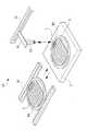
도 1은 종래의 반도체칩 적층장치를 개략적으로 나타낸 개념도이다.1 is a conceptual diagram schematically showing a conventional semiconductor chip stacking device.
도 1에서 도시된 바와 같이, 종래의 반도체칩 적층장치(10)는, 제1 또는 제2웨이퍼(W1)(W2)가 올려지는 테이블(11)과, 제1 또는 제2웨이퍼(W1)(W2)를 테이블(1)에 로딩 또는 언로딩시키는 웨이퍼 이송부(16)와, 제1반도체칩(1)을 진공압을 이용하여 픽업하는 픽커(13)와, 픽커(13)를 이동시키는 픽커 이송부(15)를 포함한다.As shown in FIG. 1, the conventional semiconductor
이와 같은 구성을 가진 종래의 반도체칩 적층장치로서 반도체칩을 적층하는 방법을 설명한다.A method of stacking semiconductor chips as a conventional semiconductor chip stacking device having such a configuration will be described.
먼저, 테이블(11)에 제1웨이퍼(W1)가 로딩(loading)된다(제1단계). 다음으로, 픽커(13)가 제1웨이퍼(W1)에 마련된 제1반도체칩(1)을 픽업한다(제2단계). 다음으로, 제1웨이퍼(W1)가 테이블(11)에 언로딩된다(제3단계). 다음으로, 제2웨이퍼(W2)가 테이블(11)에 로딩된다(제4단계). 다음으로, 픽업된 제1반도체칩(1)이 제2웨이퍼(W2)의 제2반도체칩(2)상에 다이 어태치(die attach)된다(제5단계). 다음으로, 전술한 제1 내지 제5단계를 반복하여 제2웨이퍼(W2)의 제2반도체칩(2) 모두 위에 제1반도체칩(1)을 적층하여 칩 적층공정을 종료한다.First, the first wafer W1 is loaded into the table 11 (first step). Next, the
그러나, 종래의 반도체칩 적층장치는 웨이퍼상의 반도체칩을 하나 하나 적층할 때마다 테이블에 웨이퍼를 일일이 로딩/언로딩하여야 하므로 작업시간이 늘어나게 되어, 반도체 제조공정의 생산성이 저하되는 문제점이 있다.However, in the conventional semiconductor chip stacking apparatus, since the wafers must be loaded / unloaded on the table one by one each time the semiconductor chips on the wafer are stacked one by one, the work time is increased and the productivity of the semiconductor manufacturing process is lowered.
또한, 두께가 얇은 웨이퍼의 반도체칩에 대하여 진공압을 이용한 픽커가 픽업하거나 다이 어태치하는 경우에, 픽커에 의한 충격으로 반도체칩에 균열현상 또는 휨현상이 발생하므로, 반도체 패키지의 제품 신뢰성이 저하되는 문제점이 있다.In addition, when a picker using a vacuum pressure picks up or die attaches a semiconductor chip of a thin wafer, cracking or warping of the semiconductor chip occurs due to the impact caused by the picker, thereby reducing product reliability of the semiconductor package. There is a problem.
따라서, 본 발명은 반도체 제조공정이 신속히 이루어지고, 반도체 제조공정시 반도체 패키지의 신뢰성이 보장되도록 개선된 반도체칩 적층장치, 이것을 이용한 반도체 패키지의 제조방법, 그리고 이러한 방법에 의하여 제조된 반도체 패키지를 제공하는데 목적이 있다.Accordingly, the present invention provides a semiconductor chip stacking apparatus which has a rapid semiconductor manufacturing process and is improved in the semiconductor manufacturing process to ensure the reliability of the semiconductor package, a method of manufacturing a semiconductor package using the same, and a semiconductor package manufactured by the method. The purpose is to.
본 발명에 따른 반도체칩 적층장치는, 복수의 제1반도체칩을 포함하는 제1웨 이퍼가 로딩(loading)되는 제1테이블; 그 제1반도체칩을 픽업하는 픽커; 그 픽커를 이동시키는 픽커 이송부; 및 그 제1테이블에 이격 배치되며, 그 제1반도체칩이 적층되는 복수의 제2반도체칩을 포함하는 제2웨이퍼가 로딩되는 제2테이블;을 포함하는 것을 특징으로 한다.In accordance with another aspect of the present invention, a semiconductor chip stacking apparatus includes: a first table on which a first wafer including a plurality of first semiconductor chips is loaded; A picker for picking up the first semiconductor chip; A picker transfer unit for moving the picker; And a second table spaced apart from the first table and loaded with a second wafer including a plurality of second semiconductor chips on which the first semiconductor chip is stacked.
본 발명의 바람직한 실시예에 따르면, 그 픽커 이송부는, 그 제1 및 제2테이블 중에서 선택된 어느 하나로부터 그 제1 및 제2테이블 중에서의 나머지 하나까지 그 픽커를 왕복 이동시키며, 그 제1 및 제2테이블 각각의 상면의 법선 방향으로 그 픽커를 상하 이동시키는 것을 특징으로 한다.According to a preferred embodiment of the present invention, the picker conveying unit reciprocates the picker from any one selected from the first and second tables to the other one of the first and second tables, and the first and the first and second tables. The picker is moved up and down in the normal direction of the upper surface of each of the two tables.
본 발명의 바람직한 실시예에 따르면, 그 제1테이블에 그 제1웨이퍼를 로딩 또는 언로딩시키는 제1웨이퍼 이송부와, 그 제2테이블에 그 제2웨이퍼를 로딩 또는 언로딩시키는 제2웨이퍼 이송부를 더 포함하는 것을 특징으로 한다.According to a preferred embodiment of the present invention, a first wafer transfer portion for loading or unloading the first wafer on the first table and a second wafer transfer portion for loading or unloading the second wafer on the second table are provided. It further comprises.
본 발명에 따른 반도체 패키지의 제조방법은, (a1) 각각의 저면(底面)에 제1 및 제2접착층이 형성되고, 소잉(sawing)작업이 종료된 제1 및 제2웨이퍼를 준비하는 단계; (a2) 그 제1웨이퍼를 제1테이블 상에 로딩(loading)하고, 그 제2웨이퍼를 그 제1테이블과 이격 배치되는 제2테이블 상에 로딩하는 단계; (a3) 그 제1웨이퍼에 포함된 복수의 제1반도체칩을 픽업하여, 그 제2웨이퍼에 포함된 제2반도체칩 상에 다이 어태치(die attach)하는 단계; (a4) 전술한 (a3)단계를 반복하여 그 제1반도체칩 상에 그 제2반도체칩이 적층된 복수의 2층 멀티칩을 제조하는 단계; (a5) 그 제1웨이퍼중 남겨진 제1잔여물(殘餘物)을 그 제1테이블에서 언로딩(unloading)하고, 복수의 기판이 포함된 기판 패널(substrate panel)을 그 제1테이블에 로딩하 는 단계; (a6) 그 2층 멀티칩을 그 픽커로 픽업하여, 그 기판상에 다이 어태치하는 단계; 및 (a7) 그 2층 멀티칩과 그 기판 사이를 전기적으로 연결하는 와이어 본딩을 실시하고, 그 기판의 저면에 솔더볼을 형성하며, 그 기판 패널을 절단하여 개별화하는 싱귤레이션(singulation) 작업을 실시하는 단계;를 포함하는 것을 특징으로 한다.The method of manufacturing a semiconductor package according to the present invention includes the steps of: (a1) preparing first and second wafers having first and second adhesive layers formed on respective bottom surfaces thereof, and for which sawing is completed; (a2) loading the first wafer on a first table and loading the second wafer on a second table spaced apart from the first table; (a3) picking up a plurality of first semiconductor chips included in the first wafer and die attaching the second semiconductor chips included in the second wafer; (a4) repeating the above-described step (a3) to manufacture a plurality of two-layer multi-chips having the second semiconductor chip stacked on the first semiconductor chip; (a5) unloading the first residue remaining in the first wafer in the first table, and loading a substrate panel including a plurality of substrates into the first table; The step; (a6) picking up the two-layer multichip with the picker and die attaching on the substrate; And (a7) conducting wire bonding electrically connecting the two-layer multichip and the substrate, forming solder balls on the bottom surface of the substrate, and performing a singulation operation to cut and individualize the substrate panel. It characterized in that it comprises a.
본 발명의 바람직한 실시예에 따르면, 그 제1반도체칩은 그 제1반도체칩 활성면의 법선 방향으로 측정되는 제1칩높이 및 그 제1반도체칩 활성면의 면적인 제1칩면적을 가지고, 그 제2반도체칩은 그 제2반도체칩 활성면의 법선 방향으로 측정되는 제2칩높이 및 그 제2반도체칩 활성면의 면적인 제2칩면적을 가지며, 그 제1칩높이에 대한 그 제1칩면적의 제1비율값은 그 제2칩높이에 대한 그 제2칩면적의 제2비율값보다 작거나 같은 것을 특징으로 한다.According to a preferred embodiment of the present invention, the first semiconductor chip has a first chip height measured in the normal direction of the first semiconductor chip active surface and a first chip area that is the area of the first semiconductor chip active surface, The second semiconductor chip has a second chip height measured in the normal direction of the second semiconductor chip active surface and a second chip area of the area of the second semiconductor chip active surface, and the second chip height relative to the first chip height. The first ratio value of one chip area is less than or equal to the second ratio value of the second chip area with respect to the second chip height.
본 발명의 바람직한 실시예에 따르면, 그 제1높이는 그 제2높이보다 더 크고, 그 제1면적은 그 제2면적보다 더 작은 것을 특징으로 한다.According to a preferred embodiment of the present invention, the first height is larger than the second height, and the first area is smaller than the second area.
본 발명의 바람직한 실시예에 따르면, 그 제1비율값은 100~1000mm 사이이고, 그 제2비율값은 1000~5000mm 사이인 것을 특징으로 한다.According to a preferred embodiment of the present invention, the first ratio value is between 100 and 1000 mm, and the second ratio value is between 1000 and 5000 mm.
본 발명에 따른 반도체 패키지의 다른 제조방법은, (b1) 각각의 저면(底面)에 제1 및 제2접착층이 형성되고, 소잉(sawing)작업이 종료된 제1 및 제2웨이퍼를 준비하는 단계; (b2) 그 제1웨이퍼를 제1테이블 상에 로딩(loading)하고, 그 제2웨이퍼를 그 제1테이블과 이격 배치되는 제2테이블 상에 로딩하는 단계; (b3) 그 제1웨이퍼에 포함된 복수의 제1반도체칩을 픽업하여, 그 제2웨이퍼에 포함된 제2반도 체칩 상에 다이 어태치(die attach)하는 단계; (b4) 전술한 (b3)단계를 반복하여 그 제1반도체칩 상에 그 제2반도체칩이 적층된 복수의 2층 멀티칩을 제조하는 단계; (b5) 그 제1웨이퍼중 남겨진 제1잔여물(殘餘物)을 그 제1테이블에서 언로딩(unloading)하고, 저면에 제3접착층이 형성되고 제3반도체칩을 포함하며 소잉작업이 종료된 제3웨이퍼를 그 제1테이블에 로딩하는 단계; (b6) 그 2층 멀티칩을 픽업하여, 그 제3반도체칩 상에 다이 어태치하는 단계; (b7) 전술한 (b6)단계를 반복하여 그 2층 멀티칩 상에 그 제3반도체칩이 적층된 복수의 3층 멀티칩을 제조하는 단계; (b8) 그 제1테이블에 남겨진 제2잔여물을 그 제2테이블에서 언로딩하는 단계; (b9) 전술한 (b1) 내지 (b8)단계를 반복하여 복수층 멀티칩을 제조하는 단계; (b10) 복수의 기판이 포함된 기판 패널(substrate panel)을 그 제1 및 제2테이블 중에서 그 복수층 멀티칩이 로딩되지 않은 테이블에 로딩하는 단계; (b11) 그 복수층 멀티칩을 픽업하여, 그 기판상에 다이 어태치하는 단계; 및 (b12) 그 복수층 멀티칩과 그 기판 사이를 전기적으로 연결하는 와이어 본딩을 실시하고, 그 기판의 저면에 솔더볼을 형성하며, 그 기판 패널을 절단하여 개별화하는 싱귤레이션(singulation) 작업을 실시하는 단계;를 포함하는 것을 특징으로 한다.According to another method of manufacturing a semiconductor package according to the present invention, (b1) preparing first and second wafers having first and second adhesive layers formed on respective bottom surfaces thereof and finishing sawing operations ; (b2) loading the first wafer on a first table and loading the second wafer on a second table spaced apart from the first table; (b3) picking up a plurality of first semiconductor chips included in the first wafer and die attaching the second semiconductor chip included in the second wafer; (b4) repeating the above-described step (b3) to manufacture a plurality of two-layer multi-chips having the second semiconductor chip stacked on the first semiconductor chip; (b5) unloading the first residues remaining in the first wafer at the first table, forming a third adhesive layer on the bottom, including the third semiconductor chip, and ending the sawing operation; Loading a third wafer into its first table; (b6) picking up the two-layer multichip and die attaching on the third semiconductor chip; (b7) repeating the above-described step (b6) to manufacture a plurality of three-layer multichips having the third semiconductor chips stacked on the two-layer multichips; (b8) unloading the second residue left in the first table in the second table; (b9) repeating the aforementioned steps (b1) to (b8) to manufacture a multilayer multichip; (b10) loading a substrate panel including a plurality of substrates onto a table in which the multi-layer multichips are not loaded among the first and second tables; (b11) picking up the multilayer multichip and die attaching on the substrate; And (b12) performing wire bonding electrically connecting the multilayer multichip and the substrate, forming a solder ball on the bottom surface of the substrate, and performing a singulation operation to cut and individualize the substrate panel. It characterized in that it comprises a.
본 발명의 바람직한 실시예에 따르면, 그 복수층 멀티칩에서 선택된 두 반도체칩 중에서 상측 반도체칩의 상측 칩높이에 대한 그 상측 반도체칩의 상측 칩면적의 제3비율값은, 그 복수층 멀티칩에서 선택된 두 반도체칩 중에서 하측 반도체칩의 하측 칩높이에 대한 그 하측 반도체칩의 하측 칩면적의 제4비율값보다 작거나 같은 것을 특징으로 한다.According to a preferred embodiment of the present invention, the third ratio value of the upper chip area of the upper semiconductor chip to the upper chip height of the upper semiconductor chip among the two semiconductor chips selected from the multilayer multichip is determined in the multilayer multichip. It is characterized by being smaller than or equal to a fourth ratio of the lower chip area of the lower semiconductor chip to the lower chip height of the lower semiconductor chip among the two selected semiconductor chips.
본 발명의 바람직한 실시예에 따르면, 그 상측 칩면적은 그 하측 칩면적보다 더 작은 것을 특징으로 한다.According to a preferred embodiment of the present invention, the upper chip area is smaller than the lower chip area.
본 발명에 따른 반도체 패키지의 또다른 제조방법은, (c1) 저면에 제1접착층이 형성되고 소잉(sawing)작업된 제1인터포저 패널(interposer panel)을 제1테이블 상에 로딩(loading)하고, 저면에 제2접착층이 형성되고 소잉 작업된 제1웨이퍼를 그 제1테이블과 이격 배치되는 제2테이블 상에 로딩하는 단계; (c2) 그 제1인터포저 패널에 포함된 제1인터포저를 픽커를 이용하여 픽업하여, 그 제1웨이퍼에 포함된 제1반도체칩 상에 부착하는 단계; (c3) 전술한 (c2)단계를 반복하여 그 제1반도체칩 상에 그 제1인터포저가 적층된 하나 이상의 제1복합체를 제조하는 단계; (c4) 그 제1인터포저 패널을 그 제1테이블에서 언로딩(unloading)하고, 복수의 기판이 포함된 기판 패널(substrate panel)을 그 제1테이블에 로딩하는 단계; (c5) 그 제1복합체를 그 픽커로 픽업하여, 그 기판상에 그 픽커로 다이 어태치하는 단계; (c6) 그 기판 패널을 그 제1테이블에서 언로딩하고, 그 제1복합체가 픽업되고 남은 잔여물을 그 제2테이블에서 언로딩하는 단계; (c7) 그 제1웨이퍼와 동일한 제2웨이퍼 및 그 제1인터포저와 동일한 제2인터포저에 대하여 전술한 (c1) 내지 (c3)단계를 반복하여 그 제1복합체와 동일한 제2복합체를 제조하는 단계; (c8) 그 제1반도체칩과 그 기판 사이를 전기적으로 연결하는 와이어 본딩 단계; (c9) 그 제2복합체를 그 제1복합체상에 다이 어태치하는 단계; (c10) 그 제2반도체칩과 그 기판 사이를 전기적으로 연결하는 와이어 본딩 단계; (c11) 그 제2복합체상에 그 제2반도체칩과 동일한 제3반도체칩을 다이 어태치하는 단계; (c12) 그 제3반도체칩과 그 기판 사 이를 전기적으로 연결하는 와이어 본딩 단계; 및 (c13) 그 기판의 저면에 솔더볼을 형성하며, 그 기판 패널을 절단하고 개별화하는 싱귤레이션(singulation) 작업을 실시하는 단계;를 포함하는 것을 특징으로 한다.Another method of manufacturing a semiconductor package according to the present invention comprises: (c1) loading a first interposer panel on which a first adhesive layer is formed on a bottom surface and sawing is performed on a first table; Loading a first wafer having a second adhesive layer formed on a bottom thereof, and sawing the first wafer on a second table spaced apart from the first table; (c2) picking up the first interposer included in the first interposer panel using a picker and attaching the first interposer on the first semiconductor chip included in the first wafer; (c3) repeating step (c2) described above to manufacture one or more first composites having the first interposer laminated on the first semiconductor chip; (c4) unloading the first interposer panel at the first table and loading a substrate panel including a plurality of substrates into the first table; (c5) picking up the first composite with the picker and die attaching the picker onto the substrate; (c6) unloading the substrate panel in the first table and unloading the residue left in the first table after the first composite is picked up; (c7) Repeating the steps (c1) to (c3) described above for the second wafer identical to the first wafer and the same second interposer as the first interposer, the second composite similar to the first composite is manufactured. Doing; (c8) a wire bonding step of electrically connecting the first semiconductor chip and the substrate; (c9) die attaching the second composite onto the first composite; (c10) a wire bonding step of electrically connecting the second semiconductor chip and the substrate; (c11) die attaching the same third semiconductor chip as the second semiconductor chip on the second composite; (c12) a wire bonding step of electrically connecting the third semiconductor chip and the substrate; And (c13) forming a solder ball on the bottom surface of the substrate, and performing a singulation operation of cutting and individualizing the substrate panel.
본 발명에 따른 반도체 패키지는, 제1반도체칩; 그 제1반도체칩이 다이 어태치되고, 적층된 하나 이상의 반도체칩을 포함하는 제2반도체칩군; 그 제2반도체칩군이 부착된 기판; 그 기판의 저면에 형성된 솔더볼; 및 그 제1반도체칩과 그 제2반도체칩군을 그 기판과 전기적으로 연결하는 본딩 와이어;를 포함하는 반도체 패키지에 있어서, 그 제1반도체칩은 그 제1반도체칩 활성면의 법선 방향으로 측정되는 제1칩높이 및 그 제1반도체칩 활성면의 면적인 제1칩면적을 가지고, 그 제2반도체칩군중에서 선택된 제2반도체칩은 그 제2반도체칩 활성면의 법선 방향으로 측정되는 제2칩높이 및 그 제2반도체칩 활성면의 면적인 제2칩면적을 가지며, 그 제1칩높이에 대한 그 제1칩면적의 제1비율값은 그 제2칩높이에 대한 그 제2칩면적의 제2비율값보다 더 작은 것을 특징으로 한다.A semiconductor package according to the present invention comprises: a first semiconductor chip; A second semiconductor chip group in which the first semiconductor chip is die-attached and includes one or more stacked semiconductor chips; A substrate to which the second semiconductor chip group is attached; A solder ball formed on the bottom surface of the substrate; And a bonding wire electrically connecting the first semiconductor chip and the second semiconductor chip group to the substrate, wherein the first semiconductor chip is measured in the normal direction of the active surface of the first semiconductor chip. A second semiconductor chip having a first chip height and a first chip area of the first semiconductor chip active surface, wherein the second semiconductor chip selected from the second semiconductor chip group is measured in the normal direction of the second semiconductor chip active surface Having a second chip area of the chip height and the area of the second semiconductor chip active surface, wherein a first ratio of the first chip area to the first chip height is the second chip area relative to the second chip height It is characterized in that the smaller than the second ratio value of.
본 발명의 바람직한 실시예에 따르면, 그 제1비율값은 100~1000mm 사이이고, 그 제2비율값은 1000~5000mm 사이인 것을 특징으로 한다.According to a preferred embodiment of the present invention, the first ratio value is between 100 and 1000 mm, and the second ratio value is between 1000 and 5000 mm.
본 발명의 바람직한 실시예에 따르면, 그 제1높이는 그 제2높이보다 더 큰 것을 특징으로 한다.According to a preferred embodiment of the present invention, the first height is larger than the second height.
이하. 첨부된 도면을 참조하여 본 발명에 따른 반도체칩 적층장치, 이것을 이용한 반도체 패키지의 제조방법, 그리고 이러한 방법에 의하여 제조된 반도체 패키지를 설명한다.Below. A semiconductor chip stacking apparatus, a method of manufacturing a semiconductor package using the same, and a semiconductor package manufactured by the method will be described with reference to the accompanying drawings.
우선, 본 발명에 따른 반도체칩 적층장치를 설명한다.First, a semiconductor chip stacking apparatus according to the present invention will be described.
도 2는 본 발명에 따른 반도체칩 적층장치를 개략적으로 나타낸 개념도이다. 도 2에서 도시된 바와 같이, 본 발명에 따른 반도체칩 적층장치(20)는 제1 및 제2테이블(21)(22), 제1 및 제2웨이퍼 이송부(26)(27), 픽커(23), 그리고 픽커 이송부(25)를 포함한다.2 is a conceptual diagram schematically showing a semiconductor chip stacking device according to the present invention. As shown in FIG. 2, the semiconductor
제1테이블(21)에는 복수의 제1반도체칩(1)을 포함하는 제1웨이퍼(W1)가 로딩(loading)된다. 제2테이블(22)은 제1테이블(21)과 이격 배치되며, 그 위에 제2웨이퍼(W2)가 로딩된다. 제1 및 제2웨이퍼(W1)(W2)는 각각 제1 및 제2웨이퍼 적재대(21b)(22b)에 적재될 수도 있다.A first wafer W1 including a plurality of
제1 및 제2웨이퍼 이송부(26)(27)는 각각 제1 및 제2웨이퍼(W1)(W2)를 제1 및 제2테이블(21)(22)에 로딩 또는 언로딩시킨다. 제1 및 제2웨이퍼 이송부(26)(27)는 가이드 레일 또는 엘리베이터 장치를 포함할 수도 있다.The first and second
픽커(23)는 제1반도체칩(1)을 픽업하며, 픽커 이송부(25)와 연결된 픽커 지지대(24)에 의해 지지된다. 픽커(23)는 진공압을 이용한 진공흡착픽커인 것이 바람직하다.The
픽커 이송부(25)는 픽커(23)가 제1 및 제2테이블(21)(22) 사이를 왕복할 수 있도록 한다. 즉, 픽커(23)를 V방향으로 이동시킨다. 또한, 픽커 이송부(25)는 픽커(23)가 제1 및 제2반도체칩(1)(2) 각각에 접근 또는 이격될 수 있도록 제1 및 제2테이블(21)(22)의 상면(21a)(22a) 각각의 법선 방향으로 상기 픽커를 상하 이동시킨다. 즉, 픽커(23)를 H방향으로 이동시킨다.The
도 3a 내지 도 3d는 본 발명에 따른 반도체칩 적층장치를 이용한 반도체 패키지의 제조방법을 나타낸 단면도이다. 이하에서는, 본 발명에 따른 반도체칩 적층장치를 이용한 반도체 패키지의 제조방법을 설명한다.3A to 3D are cross-sectional views illustrating a method of manufacturing a semiconductor package using a semiconductor chip stacking apparatus according to the present invention. Hereinafter, a method of manufacturing a semiconductor package using the semiconductor chip stacking device according to the present invention will be described.
먼저, 제1 및 제2웨이퍼(도 2의 W1, W2)를 준비한다. 여기서, 제1 및 제2웨이퍼(W1)(W2) 각각의 저면(底面)에는 제1 및 제2접착층(도 3a의 31)(도 3b의 32)이 형성되어 있고, 제1 및 제2웨이퍼(W1)(W2) 각각은 소잉(sawing)작업이 종료된 상태이다. 또한, 제1 및 제2접착층(31)(32)의 저면 각각에는 제1 및 제2테이프(도 3a의 33)(도 3b의 34)가 마련된다.First, first and second wafers W1 and W2 of FIG. 2 are prepared. Here, the first and second adhesive layers (31 in FIG. 3A) (32 in FIG. 3B) are formed on the bottom surfaces of the first and second wafers W1 and W2, respectively. Each of the (W1) and (W2) states that the sawing operation is completed. Further, first and second tapes (33 in Fig. 3A) (34 in Fig. 3B) are provided on the bottom surfaces of the first and second
다음으로, 도 2에서와 같이, 제1웨이퍼(W1)를 V2방향으로 이동시켜 제1테이블(21)상에 로딩(loading)하고, 제2웨이퍼(W2)를 V1방향으로 이동시켜 제1테이블(21)과 이격 배치되는 제2테이블(22)상에 로딩한다.Next, as shown in FIG. 2, the first wafer W1 is moved in the V2 direction to be loaded onto the first table 21, and the second wafer W2 is moved in the V1 direction to the first table. It loads on the 2nd table 22 arrange | positioned apart from (21).
다음으로, 도 3a에 도시된 바와 같이, 제1웨이퍼(W1)에 포함된 복수의 제1반도체칩(1)을 픽커(23)로 픽업한다.Next, as illustrated in FIG. 3A, the plurality of
다음으로, 도 3b에 도시된 바와 같이, 픽커(23)를 사용하여 제2반도체칩(2)상에 제1반도체칩(1)을 다이 어태치(die attach)하고, 이러한 다이 어태치 단계를 반복하여 제1반도체칩(1)상에 제2반도체칩(2)이 적층된 복수의 2층 멀티칩(42)을 제조한다.Next, as shown in FIG. 3B, die attach the
도 4는 본 발명에 따른 반도체 패키지 제조방법 중에서 반도체칩을 적층하는 상태를 나타낸 사시도이다. 전술한 다이 어태치 단계는 도 4를 참조하면 더욱 명확히 설명될 것이다. 본 실시예에서, 제1반도체칩(1)의 『길이×너비×높이』는 『8mm ×8mm ×100㎛』이고, 제2반도체칩(2)의 『길이×너비×높이』는 『10mm ×10mm ×30㎛』이다.4 is a perspective view illustrating a state in which semiconductor chips are stacked in a method of manufacturing a semiconductor package according to the present invention. The die attach step described above will be more clearly described with reference to FIG. 4. In the present embodiment, the "length x width x height" of the
다음으로, 도 2에 도시된 바와 같이, 제1웨이퍼(W1)중에서 남겨진 제1잔여물(殘餘物)(미도시)을 제1테이블(21)에서 언로딩(unloading)하고, 복수의 기판(도 3d의 36)이 포함된 기판 패널(substrate panel)(도 3d의 35)을 제1테이블(21)에 로딩한다.Next, as shown in FIG. 2, the first residue 21 (not shown) left in the first wafer W1 is unloaded from the first table 21, and a plurality of substrates ( A substrate panel (35 in FIG. 3D) including 36 in FIG. 3D is loaded into the first table 21.
다음으로, 도 3c에 도시된 바와 같이, 2층 멀티칩(42)을 픽커(23)로 픽업한다.Next, as shown in FIG. 3C, the two-
다음으로, 도 3d에 도시된 바와 같이, 기판(36)상에 다이 어태치한다.Next, as shown in FIG. 3D, die attach on the
다음으로, 도 3e에 도시된 바와 같이, 2층 멀티칩(42)과 기판(36) 사이를 와이어(37)를 사용하여 전기적으로 연결하는 와이어 본딩 작업을 실시하고, 기판(36)의 저면에 솔더볼(38)을 형성하며, 기판 패널(도 3d의 35)을 절단하여 개별화하는 싱귤레이션(singulation) 작업을 실시한다. 여기서, 기판(36)의 상면과 2층 멀티칩(42)을 봉지재(39)로 실링(sealing)하는 작업을 실시할 수도 있다. 이로써, 반도체 패키지(30)의 제조공정이 종료된다.Next, as shown in FIG. 3E, a wire bonding operation for electrically connecting the two-
도 3e를 참조하면, 제1반도체칩(1)은 제1반도체칩 활성면(1a)의 법선 방향(P)으로 측정되는 제1칩높이와 제1반도체칩 활성면(1a)의 면적인 제1칩면적을 가진다. 그리고, 제2반도체칩(2)은 제2반도체칩 활성면(2a)의 법선 방향(P)으로 측정되는 제2칩높이와 제2반도체칩 활성면(2a)의 면적인 제2칩면적을 가진다.Referring to FIG. 3E, the
여기서, 그 제1칩높이에 대한 그 제1칩면적의 제1비율값(제1칩면적/제1칩높 이)은 그 제2칩높이에 대한 그 제2칩면적의 제2비율값(제2칩면적/제2칩높이) 보다 작거나 같다.Here, the first ratio value (first chip area / first chip height) of the first chip area with respect to the first chip height is the second ratio value of the second chip area with respect to the second chip height ( Less than or equal to 2 chip area / second chip height).
바람직하게, 그 제1높이는 그 제2높이보다 더 크고, 그 제1면적은 그 제2면적보다 더 작게 한다. 또한, 그 제1비율값은 100~1000mm 사이이고, 그 제2비율값은 1000~5000mm 사이인 것이 바람직하다.Preferably, the first height is greater than the second height, and the first area is smaller than the second area. Moreover, it is preferable that the 1st ratio value is between 100-1000 mm, and the 2nd ratio value is between 1000-5000 mm.
본 실시예에서는 기판상에 반도체칩이 2층 적층된 경우를 설명하였지만, 기판상에 3층 이상의 반도체칩이 적층될 수도 있다.In the present embodiment, a case where two semiconductor chips are stacked on a substrate has been described, but three or more semiconductor chips may be stacked on a substrate.
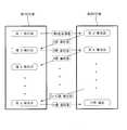
도 5는 본 발명에 따른 반도체 패키지의 제조공정 중에서 복수의 반도체칩을 적층하는 과정을 개념적으로 나타낸 다이어 그램이다. 이하에서는 도 5를 참조하여 본 발명에 따른 반도체 패키지의 제조공정 중에서 복수의 반도체칩을 적층하는 과정을 설명한다.5 is a diagram conceptually illustrating a process of stacking a plurality of semiconductor chips in a manufacturing process of a semiconductor package according to the present invention. Hereinafter, a process of stacking a plurality of semiconductor chips in the manufacturing process of the semiconductor package according to the present invention will be described with reference to FIG. 5.
먼저, 제1테이블에 제1웨이퍼가 로딩되고 제2테이블에 제2웨이퍼가 로딩된다. 다음으로, 제1웨이퍼의 제1반도체칩이 제2웨이퍼의 제2반도체칩 상으로 다이 어태치되어 2층 멀티칩이 제조된다. 다음으로, 제1테이블에 제1웨이퍼의 제1잔여물이 언로딩되고 제3웨이퍼가 로딩된다. 다음으로, 그 2층 멀티칩이 제3웨이퍼의 제3반도체칩 상으로 다이 어태치되어 3층 멀티칩이 제조된다. 다음으로, 제2테이블에 제2웨이퍼의 제2잔여물이 언로딩되고 제4웨이퍼가 로딩된다. 다음으로, 그 3층 멀티칩이 제4웨이퍼의 제4반도체칩 상으로 다이 어태치되어 4층 멀티칩이 제조된다. 다음으로, 전술한 적층 과정을 반복하여 제1테이블에 로딩된 제n웨이퍼의 제n반도체칩 상에 (n-1)층 멀티칩이 다이 어태치된다(여기서 n은 6이상의 자연수이다). 다 음으로, n층 멀티칩을 제2테이블에 로딩된 기판 패널에 다이 어태치한다. 여기서, 기판 패널은 제1테이블에 로딩되어, 제2테이블에 로딩된 (n-1)층 멀티칩이 제1테이블에 로딩된 기판 패널에 다이 어태치될 수도 있다.First, a first wafer is loaded on a first table and a second wafer is loaded on a second table. Next, the first semiconductor chip of the first wafer is die-attached onto the second semiconductor chip of the second wafer to manufacture a two-layer multichip. Next, the first residue of the first wafer is unloaded and the third wafer is loaded into the first table. Next, the two-layer multichip is die-attached onto the third semiconductor chip of the third wafer to produce a three-layer multichip. Next, the second residue of the second wafer is unloaded and the fourth wafer is loaded into the second table. Next, the three-layer multichip is die-attached onto the fourth semiconductor chip of the fourth wafer to produce a four-layer multichip. Next, the (n-1) layer multi-chip is die-attached on the n-th semiconductor chip of the n-th wafer loaded on the first table by repeating the above-described lamination process (where n is a natural number of 6 or more). Next, the n-layer multichip is die-attached to the substrate panel loaded on the second table. Here, the substrate panel may be loaded on the first table, and the (n-1) layer multichip loaded on the second table may be die attached to the substrate panel loaded on the first table.
따라서, 본 발명에 따른 반도체칩 적층장치를 이용한 반도체 패키지의 제조방법에 의하여, 종래의 반도체칩 적층장치의 경우 보다 더 간편하고 신속하게 반도체칩을 적층할 수 있다.Therefore, according to the method of manufacturing a semiconductor package using the semiconductor chip stacking device according to the present invention, it is possible to stack the semiconductor chips more simply and quickly than the conventional semiconductor chip stacking device.
또한, 픽커 등 외부의 충격에도 균열이나 휘어짐이 발생되지 않을 정도의 칩면적과 후막(厚膜)(약 100㎛)을 가진 제1반도체가 약 30㎛ 두께의 박막(薄膜)을 가진 제2반도체칩에 다이 어태치되므로, 그 제1반도체칩이 그 제2반도체칩에 대해지지 보강재(支持 補强材) 역할을 하여 픽커 등 외부의 충격에도 제2반도체칩의 박막(薄膜)에 균열이나 휘어짐이 억제된다.In addition, a second semiconductor having a thin film having a thickness of about 30 μm and a first semiconductor having a chip area and a thick film (about 100 μm) that are not cracked or warped by an external impact such as a picker. Since the die attach to the chip, the first semiconductor chip acts as a support reinforcement for the second semiconductor chip, so that the thin film of the second semiconductor chip is cracked or warped under external impact such as a picker. This is suppressed.
도 6은 본 발명의 일실시예에 따른 반도체 패키지를 나타낸 단면도이다. 도 6에 도시된 바와 같이, 세임 다이 스택(same die stack) 구조를 가지는 반도체 패키지(100)는 기판(140), 제1 내지 제3반도체칩(113)(123)(133), 제1 및 제2인터포저(111)(121), 제1 내지 제3본딩 와이어(151)(152)(153), 그리고 봉지재(160)를 포함한다.6 is a cross-sectional view illustrating a semiconductor package according to an embodiment of the present invention. As shown in FIG. 6, the
기판(140)은 그 저면에 솔더볼(141)이 형성된다. 제1 내지 제3반도체칩(113)(123)(133)은 기판(140)상에 적층되며, 각각의 저면에 제2, 제4 및 제5접착층(114)(124)(134)이 마련된다. 제1 내지 제3반도체칩(113)(123)(133)은 서로 동일한 크기를 가진다. 제1 및 제2인터포저(111)(121)는 각각의 저면에 제1 및 제3접착층(112)(122)이 마련되고, 제1 내지 제3반도체칩(113)(123)(133) 사이에 개재되어 제1 내지 제3반도체칩(113)(123)(133) 각각을 서로 이격시킨다. 제1 내지 제3본딩 와이어(151)(152)(153)는 제1 내지 제3반도체칩(113)(123)(133)과 기판(140)을 각각 전기적으로 연결한다. 봉지재(160)는 기판(140)의 상면과 제1 내지 제3반도체칩(113)(123)(133)을 실링한다.The
여기서, 제1 및 제2접착층(112)(114)을 각각 포함하는 제1인터포저(111) 및 제1반도체칩(113)은 제1복합체(110)로 구성된다. 그리고 제3 및 제4접착층(122)(124)을 각각 포함하는 제2인터포저(121) 및 제1반도체칩(123)은 제2복합체(120)로 구성된다.Here, the
이하에서는 반도체 패키지(100)를 제조하는 방법을 설명한다. 본 실시예의 제조방법에서는 앞서 도 2에서 설명된 반도체칩 적층장치(20)가 사용되며, 여기서 적층되는 반도체칩은 세임 다이 스택 구조이다.Hereinafter, a method of manufacturing the
먼저, 저면에 제1접착층(112)이 형성되고 소잉(sawing)작업된 제1인터포저 패널(interposer panel)(미도시)을 제1테이블(도 2의 21)상에 로딩(loading)하고, 저면에 제2접착층(114)이 형성되고 소잉 작업된 제1웨이퍼(미도시)를 제2테이블(22)상에 로딩한다.First, a first
다음으로, 그 제1인터포저 패널에 포함된 제1인터포저(111)를 픽커(도 2의 23)를 이용하여 픽업하여, 그 제1웨이퍼에 포함된 제1반도체칩(113)상에 부착하여 제1복합체(110)를 제조한다.Next, the
다음으로, 그 제1인터포저 패널을 제1테이블(도 2의 21)에서 언로딩(unloading)하고, 기판(140)이 포함된 기판 패널(substrate panel)(미도시)을 제1테이블(도 2의 21)에 로딩한다.Next, the first interposer panel is unloaded from the first table (21 in FIG. 2), and the substrate panel (not shown) including the
다음으로, 제1복합체(110)를 픽커(도 2의 23)로 픽업하여, 제2테이블(도 2의 22)상에 있는 기판(140)상에 다이 어태치한다.Next, the first
다음으로, 그 기판 패널을 제1테이블(도 2의 21)에서 언로딩하고, 제1복합체(110)가 픽업되고 남은 잔여물(미도시)을 제2테이블(도 2의 22)에서 언로딩한다.Next, the substrate panel is unloaded from the first table (21 in FIG. 2), and the residue (not shown) left after the
다음으로, 그 제1웨이퍼와 동일한 제2웨이퍼 및 제1인터포저(111)와 동일한 제2인터포저(121)에 대하여 전술한 제조공정을 반복하여 제1복합체(110)와 동일한 제2복합체(120)를 제조한다.Next, the above-described manufacturing process is repeated with respect to the second wafer identical to the first wafer and the
다음으로, 제1반도체칩(113)과 기판(140) 사이를 제1본딩 와이어(151)로 전기적으로 연결한다.Next, the
다음으로, 제2복합체(120)를 제1복합체(110)상에 다이 어태치한다. 이 때, 도 2의 반도체칩 적층장치(20)를 사용하여 다이 어태치할 수도 있다.Next, the second
다음으로, 제2반도체칩(123)과 기판(140) 사이를 제2본딩 와이어(152)로 전기적으로 연결한다.Next, the
다음으로, 제2복합체(120)상에 제2반도체칩(123)과 동일한 제3반도체칩(133)을 다이 어태치한다. 이 때, 도 2의 반도체칩 적층장치(20)를 사용하여 다이 어태치할 수도 있다.Next, the
다음으로, 제3반도체칩(133)과 기판(140) 사이를 제3본딩 와이어(153)로 전 기적으로 연결한다.Next, the
다음으로, 기판(140)의 저면에 솔더볼(141)을 형성하고, 봉지재(160)를 형성하며, 기판 패널을 절단하고 개별화하는 싱귤레이션(singulation) 작업을 실시한다. 이로써 반도체 패키지 제조가 종료된다.Next, the
본 실시예에서는 3개의 반도체칩들과 그 반도체칩들 사이에 개재되는 2개의 인터포저를 포함하는 반도체 패키지 및 그 제조방법에 대하여 설명하였으나, 복수의 반도체칩들과 그 반도체칩들 사이에 개재되는 복수의 인터포저를 포함하는 반도체 패키지 및 그 제조방법도 본 발명의 범주에 해당될 것이다.In the present embodiment, a semiconductor package including three semiconductor chips and two interposers interposed between the semiconductor chips and a method of manufacturing the same are described. However, the plurality of semiconductor chips and the semiconductor chips are interposed between the semiconductor chips and the semiconductor chips. A semiconductor package including a plurality of interposers and a method of manufacturing the same will also fall within the scope of the present invention.
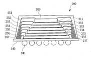
도 7은 본 발명의 다른 실시예에 따른 반도체 패키지를 나타낸 단면도이다.7 is a cross-sectional view illustrating a semiconductor package in accordance with another embodiment of the present invention.
도 7에 도시된 바와 같이, 본 발명의 다른 실시예에 따른 반도체 패키지(200)는 기판(240), 제1 내지 제7반도체칩(211) 내지 (217), 제1 내지 제7본딩 와이어(251) 내지 (257), 그리고 봉지재(260)를 포함한다.As illustrated in FIG. 7, the
기판(240)은 그 저면에 솔더볼(241)이 형성된다. 제1 내지 제7반도체칩(211) 내지 (217)는 기판(240)상에 적층된다. 여기서, 제1반도체칩(211)의 『길이×너비×높이』는 『8mm ×8mm ×100㎛』이고, 제2반도체칩(212)의 『길이×너비×높이』는 『10mm ×10mm ×30㎛』이다. 제3 내지 제7반도체칩(213) 내지 (217)의 두께는 모두 같지만, 각각의 칩면적은 상측 반도체칩이 하측 반도체칩보다 더 작자. 제1 내지 제7본딩 와이어(251) 내지 (257)는 각각 제1 내지 제7반도체칩(211) 내지 (217) 각각과 기판(240)을 전기적으로 연결한다. 봉지재(260)는 기판(260)의 상면과 제1 내지 제7반도체칩(211) 내지 (217)을 실링한다.The
여기서, 제1 내지 제7반도체칩(211) 내지 (217) 중에서 2개의 반도체가 선택되어 상측 및 하측 반도체칩이 지정된다. 그리고 그 상측 반도체칩의 제1칩높이에 대한 그 상측 반도체칩의 제1칩면적의 제1비율값(제1칩면적/제1칩높이)은 그 하측 반도체칩의 제2칩높이에 대한 그 하측 반도체칩의 제2칩면적의 제2비율값(제2칩면적/제2칩높이) 보다 더 작다. 구체적으로 예를 들면, 본 실시예에서 제1반도체칩(211)의 『길이×너비×높이』는 『8mm ×8mm ×100㎛』이고, 제2반도체칩(212)의 『길이×너비×높이』는 『10mm ×10mm ×30㎛』이므로, 제1비율값은 640mm 이고 제2비율값은 약 3333mm 이다. 따라서, 제1비율값이 제2비율값보다 작게 됨을 알 수 있다.Here, two semiconductors are selected from the first to
바람직하게는, 제1비율값이 100~1000mm 사이이고, 제2비율값은 1000~5000mm 사이가 되도록 한다. 또한, 제1 내지 제7반도체칩(211) 내지 (217) 중에서 선택된 두 반도체칩 중에서 상측 반도체칩의 두께는, 제1 내지 제7반도체칩(211) 내지 (217) 중에서 선택된 두 반도체칩 중에서 하측 반도체칩의 두께보다 더 큰 것이 바람직하다.Preferably, the first ratio value is between 100 and 1000 mm, and the second ratio value is between 1000 and 5000 mm. The thickness of the upper semiconductor chip among the two semiconductor chips selected from the first to
이상, 본 발명의 원리를 예시하기 위한 바람직한 실시예에 대하여 도시하고 설명하였으나, 본 발명은 그와 같이 도시되고 설명된 그대로의 구성 및 작용으로 한정되는 것이 아니다. 오히려, 첨부된 특허청구범위의 사상 및 범주를 일탈함이 없이 본 발명에 대한 다양한 변경 및 수정이 가능함을 당업자들은 잘 이해할 수 있을 것이다. 따라서, 그러한 모든 적절한 변경과 수정 및 균등물들도 본 발명의 범위에 속하는 것으로 간주되어야 할 것이다.As mentioned above, although the preferred embodiment for illustrating the principle of this invention was shown and demonstrated, this invention is not limited to the structure and operation as it was shown and described. Rather, those skilled in the art will appreciate that various changes and modifications can be made to the present invention without departing from the spirit and scope of the appended claims. Accordingly, all such suitable changes, modifications, and equivalents should be considered to be within the scope of the present invention.
본 발명에 따른 반도체칩 적층장치는, 2개의 웨이퍼가 각각 별도로 로딩되는 2개의 테이블, 그 2개의 웨이퍼에 각각 포함된 2종류의 반도체칩들을 픽업하는 픽커, 그 픽커를 그 2개의 테이블 사이로 왕복 이동시키는 픽커 이송부를 포함하는 구성으로써, 반도체칩을 적층하는 공정이 간편하고 신속하게 되어 반도체 패키지의 제조공정의 생산성이 향상되는 이점이 있다.The semiconductor chip stacking apparatus according to the present invention comprises two tables each having two wafers loaded separately, a picker for picking up two kinds of semiconductor chips each included in the two wafers, and the picker reciprocating between the two tables. With the configuration including the picker transfer unit, the process of stacking the semiconductor chips can be easily and quickly, and the productivity of the manufacturing process of the semiconductor package is improved.
또한, 후막(厚膜)의 반도체칩을 박막(薄膜)의 반도체칩에 다이 어태치하여 멀티칩을 구성하여 후막(厚膜)의 반도체칩이 박막(薄膜)의 반도체칩의 보강 지지재 역할을 하므로, 픽커 등의 외부 충격에 의한 반도체칩의 균열 또는 휘어짐이 억제되어 반도체 패키지의 제품 신뢰성이 향상되는 이점이 있다.In addition, a thick film semiconductor chip is die-attached to a thin film semiconductor chip to form a multi chip, and the thick semiconductor chip serves as a reinforcing support material for the thin film semiconductor chip. Therefore, cracks or warpage of the semiconductor chip due to external impact such as pickers are suppressed, thereby improving the product reliability of the semiconductor package.
Claims (14)
Translated fromKoreanPriority Applications (5)
| Application Number | Priority Date | Filing Date | Title |
|---|---|---|---|
| KR1020030063132AKR100541395B1 (en) | 2003-09-09 | 2003-09-09 | Semiconductor chip stacking device, manufacturing method of semiconductor package using same, and semiconductor package manufactured by such method |
| US10/916,094US7135353B2 (en) | 2003-09-09 | 2004-08-10 | Apparatus for stacking semiconductor chips, method for manufacturing semiconductor package using the same and semiconductor package manufactured thereby |
| JP2004255890AJP4434887B2 (en) | 2003-09-09 | 2004-09-02 | Manufacturing method of semiconductor package |
| US11/534,924US7374966B2 (en) | 2003-09-09 | 2006-09-25 | Apparatus for stacking semiconductor chips, method for manufacturing semiconductor package using the same and semiconductor package manufactured thereby |
| US12/102,778US20080191364A1 (en) | 2003-09-09 | 2008-04-14 | Apparatus for stacking semiconductor chips, method for manufacturing semiconductor package using the same and semiconductor package manufactured thereby |
Applications Claiming Priority (1)
| Application Number | Priority Date | Filing Date | Title |
|---|---|---|---|
| KR1020030063132AKR100541395B1 (en) | 2003-09-09 | 2003-09-09 | Semiconductor chip stacking device, manufacturing method of semiconductor package using same, and semiconductor package manufactured by such method |
Publications (2)
| Publication Number | Publication Date |
|---|---|
| KR20050026157A KR20050026157A (en) | 2005-03-15 |
| KR100541395B1true KR100541395B1 (en) | 2006-01-11 |
Family
ID=34225476
Family Applications (1)
| Application Number | Title | Priority Date | Filing Date |
|---|---|---|---|
| KR1020030063132AExpired - Fee RelatedKR100541395B1 (en) | 2003-09-09 | 2003-09-09 | Semiconductor chip stacking device, manufacturing method of semiconductor package using same, and semiconductor package manufactured by such method |
Country Status (3)
| Country | Link |
|---|---|
| US (3) | US7135353B2 (en) |
| JP (1) | JP4434887B2 (en) |
| KR (1) | KR100541395B1 (en) |
Families Citing this family (54)
| Publication number | Priority date | Publication date | Assignee | Title |
|---|---|---|---|---|
| CN103646848B (en)* | 2004-06-04 | 2018-06-05 | 伊利诺伊大学评议会 | The method of assembling printable semiconductor elements and manufacture electronic device |
| SG130055A1 (en)* | 2005-08-19 | 2007-03-20 | Micron Technology Inc | Microelectronic devices, stacked microelectronic devices, and methods for manufacturing microelectronic devices |
| SG130066A1 (en) | 2005-08-26 | 2007-03-20 | Micron Technology Inc | Microelectronic device packages, stacked microelectronic device packages, and methods for manufacturing microelectronic devices |
| KR100707717B1 (en)* | 2005-10-04 | 2007-04-16 | 주식회사 프로텍 | Semiconductor chip stacking method and apparatus |
| US20070210426A1 (en)* | 2006-03-07 | 2007-09-13 | Gerber Mark A | Gold-bumped interposer for vertically integrated semiconductor system |
| CN101426875A (en)* | 2006-04-27 | 2009-05-06 | 住友电木株式会社 | Adhesive tape, semiconductor package, and electronic device |
| USD573553S1 (en)* | 2007-02-09 | 2008-07-22 | Matsushita Electric Industrial Co., Ltd. | Light source of light-emitting diode |
| USD577690S1 (en)* | 2007-05-25 | 2008-09-30 | Matsushita Electric Industrial Co., Ltd. | Light source of light emitting diode |
| USD576576S1 (en)* | 2007-05-25 | 2008-09-09 | Matsushita Electric Industrial Co., Ltd. | Light source of light emitting diode |
| DE102007048397B3 (en)* | 2007-10-09 | 2008-11-20 | Siemens Ag | Semiconductor chip delivering device for automatic assembly of component carrier, has provision plane receiving wafer and arranged above another provision plane, and transfer devices assigned to one of provision planes |
| DE102009013353B3 (en)* | 2009-03-16 | 2010-10-07 | Siemens Aktiengesellschaft | Method for determining armor for constant tables of placement machines |
| JP2010245383A (en)* | 2009-04-08 | 2010-10-28 | Elpida Memory Inc | Semiconductor device and method of manufacturing the same |
| USD658602S1 (en)* | 2010-06-15 | 2012-05-01 | Toshiba Lighting & Technology Corporation | Light emitting diode module |
| USD658601S1 (en)* | 2010-06-15 | 2012-05-01 | Toshiba Lighting & Technology Corporation | Light emitting diode module |
| USD658603S1 (en)* | 2010-06-15 | 2012-05-01 | Toshiba Lighting & Technology Corporation | Light emitting diode module |
| US8564000B2 (en) | 2010-11-22 | 2013-10-22 | Cree, Inc. | Light emitting devices for light emitting diodes (LEDs) |
| USD676000S1 (en)* | 2010-11-22 | 2013-02-12 | Cree, Inc. | Light emitting device package |
| USD721339S1 (en) | 2010-12-03 | 2015-01-20 | Cree, Inc. | Light emitter device |
| USD712850S1 (en)* | 2010-11-18 | 2014-09-09 | Cree, Inc. | Light emitter device |
| USD707192S1 (en) | 2010-11-18 | 2014-06-17 | Cree, Inc. | Light emitting device |
| US8624271B2 (en) | 2010-11-22 | 2014-01-07 | Cree, Inc. | Light emitting devices |
| USD650760S1 (en)* | 2010-11-22 | 2011-12-20 | Cree, Inc. | Light emitting device package |
| US9490235B2 (en) | 2010-11-22 | 2016-11-08 | Cree, Inc. | Light emitting devices, systems, and methods |
| US9000470B2 (en) | 2010-11-22 | 2015-04-07 | Cree, Inc. | Light emitter devices |
| US8575639B2 (en) | 2011-02-16 | 2013-11-05 | Cree, Inc. | Light emitting devices for light emitting diodes (LEDs) |
| US9300062B2 (en) | 2010-11-22 | 2016-03-29 | Cree, Inc. | Attachment devices and methods for light emitting devices |
| USD706231S1 (en) | 2010-12-03 | 2014-06-03 | Cree, Inc. | Light emitting device |
| US8809880B2 (en) | 2011-02-16 | 2014-08-19 | Cree, Inc. | Light emitting diode (LED) chips and devices for providing failure mitigation in LED arrays |
| US8455908B2 (en) | 2011-02-16 | 2013-06-04 | Cree, Inc. | Light emitting devices |
| USD702653S1 (en) | 2011-10-26 | 2014-04-15 | Cree, Inc. | Light emitting device component |
| USD705181S1 (en) | 2011-10-26 | 2014-05-20 | Cree, Inc. | Light emitting device component |
| KR20140097284A (en) | 2011-11-07 | 2014-08-06 | 크리,인코포레이티드 | High voltage array light emitting diode(led) devices, fixtures and methods |
| KR20130066234A (en)* | 2011-12-12 | 2013-06-20 | 삼성전자주식회사 | Fabricating method of semiconductor device and appratus for pick-up of semiconductor device used thereof |
| KR101923531B1 (en) | 2011-12-23 | 2018-11-30 | 삼성전자주식회사 | Apparatus of bonding semiconductor chip |
| US8987066B2 (en)* | 2012-01-03 | 2015-03-24 | Honeywell International Inc. | Processing unit comprising integrated circuits including a common configuration of electrical interconnects |
| USD689451S1 (en)* | 2012-01-24 | 2013-09-10 | Toyoda Gosei Co., Ltd. | Light emitting diode |
| USD689450S1 (en)* | 2012-01-24 | 2013-09-10 | Toyoda Gosei Co., Ltd. | Light emitting diode |
| USD729751S1 (en) | 2012-03-29 | 2015-05-19 | Nichia Corporation | Light emitting diode |
| US9735198B2 (en) | 2012-03-30 | 2017-08-15 | Cree, Inc. | Substrate based light emitter devices, components, and related methods |
| US10134961B2 (en) | 2012-03-30 | 2018-11-20 | Cree, Inc. | Submount based surface mount device (SMD) light emitter components and methods |
| USD740768S1 (en)* | 2012-06-15 | 2015-10-13 | Toyoda Gosei Co., Ltd. | Light emitting diode |
| USD717252S1 (en)* | 2012-07-05 | 2014-11-11 | Toyoda Gosei Co., Ltd. | Light emitting diode |
| USD698322S1 (en)* | 2012-07-05 | 2014-01-28 | Toyoda Gosei Co., Ltd. | Light emitting diode |
| USD727273S1 (en)* | 2012-09-27 | 2015-04-21 | Nichia Corporation | Light emitting diode |
| US9345091B2 (en) | 2013-02-08 | 2016-05-17 | Cree, Inc. | Light emitting device (LED) light fixture control systems and related methods |
| JP2014154697A (en)* | 2013-02-08 | 2014-08-25 | Toshiba Corp | Semiconductor device, semiconductor device manufacturing method |
| USD777121S1 (en)* | 2013-03-05 | 2017-01-24 | Luminus Devices, Inc. | LED package |
| USD739565S1 (en) | 2013-06-27 | 2015-09-22 | Cree, Inc. | Light emitter unit |
| USD740453S1 (en) | 2013-06-27 | 2015-10-06 | Cree, Inc. | Light emitter unit |
| US10312118B2 (en)* | 2014-01-16 | 2019-06-04 | Taiwan Semiconductor Manufacturing Co., Ltd. | Bonding apparatus and method |
| USD823492S1 (en) | 2016-10-04 | 2018-07-17 | Cree, Inc. | Light emitting device |
| KR102404058B1 (en) | 2017-12-28 | 2022-05-31 | 삼성전자주식회사 | Semiconductor package |
| CN109638142A (en)* | 2019-01-22 | 2019-04-16 | 先进光电器材(深圳)有限公司 | Brilliant loop device |
| USD905648S1 (en)* | 2019-04-24 | 2020-12-22 | Patrick Art Ivs | LCD display |
Family Cites Families (27)
| Publication number | Priority date | Publication date | Assignee | Title |
|---|---|---|---|---|
| KR0175267B1 (en)* | 1995-09-30 | 1999-04-01 | 김광호 | Die bonding device with pick-up tool for rotary motion |
| CA2198305A1 (en)* | 1996-05-01 | 1997-11-02 | Yinon Degani | Integrated circuit bonding method and apparatus |
| US6221654B1 (en)* | 1996-09-25 | 2001-04-24 | California Institute Of Technology | Method and apparatus for analysis and sorting of polynucleotides based on size |
| KR100199293B1 (en) | 1996-11-08 | 1999-06-15 | 윤종용 | Semiconductor package manufacturing device |
| US6080219A (en) | 1998-05-08 | 2000-06-27 | Mott Metallurgical Corporation | Composite porous media |
| KR100317648B1 (en)* | 1998-08-26 | 2002-02-19 | 윤종용 | Semiconductor device having die adhesively bonded by electrically insulating tape, method and apparatus for die bonding |
| US6820792B2 (en)* | 1998-09-30 | 2004-11-23 | Samsung Electronics Co., Ltd. | Die bonding equipment |
| JP3512657B2 (en) | 1998-12-22 | 2004-03-31 | シャープ株式会社 | Semiconductor device |
| KR20000045488A (en) | 1998-12-30 | 2000-07-15 | 이계철 | Supervision and control method for disperse management system's obstruction |
| US6117704A (en) | 1999-03-31 | 2000-09-12 | Irvine Sensors Corporation | Stackable layers containing encapsulated chips |
| US6376904B1 (en) | 1999-12-23 | 2002-04-23 | Rambus Inc. | Redistributed bond pads in stacked integrated circuit die package |
| US6344401B1 (en) | 2000-03-09 | 2002-02-05 | Atmel Corporation | Method of forming a stacked-die integrated circuit chip package on a water level |
| KR100345166B1 (en) | 2000-08-05 | 2002-07-24 | 주식회사 칩팩코리아 | Wafer level stack package and method of fabricating the same |
| KR100535848B1 (en)* | 2000-09-29 | 2005-12-12 | 히다치 가세고교 가부시끼가이샤 | Resin-sealed Semiconductor Device, and Die Bonding Material and Sealing Material for Use Therein |
| KR100389513B1 (en)* | 2000-12-07 | 2003-06-27 | 삼성전자주식회사 | Apparatus For Removing Wafer Ring Tape |
| KR100729051B1 (en) | 2000-12-29 | 2007-06-14 | 앰코 테크놀로지 코리아 주식회사 | Semiconductor package and manufacturing method |
| US6503776B2 (en) | 2001-01-05 | 2003-01-07 | Advanced Semiconductor Engineering, Inc. | Method for fabricating stacked chip package |
| US20030008476A1 (en) | 2001-07-06 | 2003-01-09 | Wen Hsu | Method of fabricating a wafer level package |
| KR100394808B1 (en) | 2001-07-19 | 2003-08-14 | 삼성전자주식회사 | Wafer level stack chip package and method for manufacturing the same |
| JP3636127B2 (en)* | 2001-10-12 | 2005-04-06 | 松下電器産業株式会社 | Electronic component mounting apparatus and electronic component mounting method |
| US6747348B2 (en) | 2001-10-16 | 2004-06-08 | Micron Technology, Inc. | Apparatus and method for leadless packaging of semiconductor devices |
| KR100436656B1 (en)* | 2001-12-17 | 2004-06-22 | 미래산업 주식회사 | method for teaching working position in semiconductor test handler |
| JP3507059B2 (en)* | 2002-06-27 | 2004-03-15 | 沖電気工業株式会社 | Stacked multi-chip package |
| KR100451586B1 (en)* | 2002-03-13 | 2004-10-08 | 미래산업 주식회사 | Appratus for teaching a height for work of semiconductor transfer in handler and method for teaching the height for work using the same |
| KR100484088B1 (en)* | 2002-12-06 | 2005-04-20 | 삼성전자주식회사 | Die attach and cure in line apparatus for multi chip package |
| KR100491304B1 (en)* | 2003-09-18 | 2005-05-24 | 미래산업 주식회사 | Sorting Handler for Burn-in Tester |
| KR100640597B1 (en)* | 2004-11-15 | 2006-11-01 | 삼성전자주식회사 | Wafer Level Package Manufacturing Equipment and Manufacturing Method |
- 2003
- 2003-09-09KRKR1020030063132Apatent/KR100541395B1/ennot_activeExpired - Fee Related
- 2004
- 2004-08-10USUS10/916,094patent/US7135353B2/ennot_activeExpired - Fee Related
- 2004-09-02JPJP2004255890Apatent/JP4434887B2/ennot_activeExpired - Fee Related
- 2006
- 2006-09-25USUS11/534,924patent/US7374966B2/ennot_activeExpired - Fee Related
- 2008
- 2008-04-14USUS12/102,778patent/US20080191364A1/ennot_activeAbandoned
Also Published As
| Publication number | Publication date |
|---|---|
| KR20050026157A (en) | 2005-03-15 |
| JP2005086206A (en) | 2005-03-31 |
| US7135353B2 (en) | 2006-11-14 |
| JP4434887B2 (en) | 2010-03-17 |
| US20080191364A1 (en) | 2008-08-14 |
| US20050054140A1 (en) | 2005-03-10 |
| US7374966B2 (en) | 2008-05-20 |
| US20070018295A1 (en) | 2007-01-25 |
Similar Documents
| Publication | Publication Date | Title |
|---|---|---|
| KR100541395B1 (en) | Semiconductor chip stacking device, manufacturing method of semiconductor package using same, and semiconductor package manufactured by such method | |
| US10629461B2 (en) | Apparatuses for bonding semiconductor chips | |
| US9397072B2 (en) | Method of manufacturing semiconductor device | |
| KR101478836B1 (en) | Semiconductor package | |
| JP3014347B2 (en) | Die bonding apparatus having multiple bonding systems | |
| US6469376B2 (en) | Die support structure | |
| US20070170569A1 (en) | In-line apparatus and method for manufacturing double-sided stacked multi-chip packages | |
| US10074628B2 (en) | System-in-package and fabrication method thereof | |
| CN101038891A (en) | Manufacturing method of semiconductor device | |
| KR20110124063A (en) | Stacked Semiconductor Packages | |
| TWI876375B (en) | Modular semiconductor devices and electronic devices incorporating the same | |
| Yano et al. | Three-dimensional very thin stacked packaging technology for SiP | |
| US10090278B2 (en) | Semiconductor packages | |
| KR20110138788A (en) | Stacked Semiconductor Packages | |
| US20220165709A1 (en) | Stacked semiconductor package and packaging method thereof | |
| US6798055B2 (en) | Die support structure | |
| TW201434094A (en) | Chip package process and chip package | |
| JP2010087035A (en) | Apparatus for manufacturing three-dimensional semiconductor device and method for manufacturing same | |
| CN219842978U (en) | Small-size Hybrid packaging structure capable of reducing underfill overflow range | |
| KR20030095035A (en) | Chip size stack package using resin-spacer | |
| KR20110107125A (en) | Semiconductor package | |
| TW202213559A (en) | Semiconductor device and method for manufacturing same | |
| CN114927457A (en) | Ultra-thin ultra-small chip packaging process and chip mounting process | |
| JP2025115291A (en) | Semiconductor manufacturing equipment | |
| CN120261303A (en) | Packaging method for staggered stacked chips on a redistribution layer |
Legal Events
| Date | Code | Title | Description |
|---|---|---|---|
| A201 | Request for examination | ||
| PA0109 | Patent application | St.27 status event code:A-0-1-A10-A12-nap-PA0109 | |
| PA0201 | Request for examination | St.27 status event code:A-1-2-D10-D11-exm-PA0201 | |
| R18-X000 | Changes to party contact information recorded | St.27 status event code:A-3-3-R10-R18-oth-X000 | |
| PG1501 | Laying open of application | St.27 status event code:A-1-1-Q10-Q12-nap-PG1501 | |
| PN2301 | Change of applicant | St.27 status event code:A-3-3-R10-R13-asn-PN2301 St.27 status event code:A-3-3-R10-R11-asn-PN2301 | |
| PN2301 | Change of applicant | St.27 status event code:A-3-3-R10-R13-asn-PN2301 St.27 status event code:A-3-3-R10-R11-asn-PN2301 | |
| R17-X000 | Change to representative recorded | St.27 status event code:A-3-3-R10-R17-oth-X000 | |
| E902 | Notification of reason for refusal | ||
| PE0902 | Notice of grounds for rejection | St.27 status event code:A-1-2-D10-D21-exm-PE0902 | |
| E13-X000 | Pre-grant limitation requested | St.27 status event code:A-2-3-E10-E13-lim-X000 | |
| P11-X000 | Amendment of application requested | St.27 status event code:A-2-2-P10-P11-nap-X000 | |
| P13-X000 | Application amended | St.27 status event code:A-2-2-P10-P13-nap-X000 | |
| E701 | Decision to grant or registration of patent right | ||
| PE0701 | Decision of registration | St.27 status event code:A-1-2-D10-D22-exm-PE0701 | |
| GRNT | Written decision to grant | ||
| PR0701 | Registration of establishment | St.27 status event code:A-2-4-F10-F11-exm-PR0701 | |
| PR1002 | Payment of registration fee | St.27 status event code:A-2-2-U10-U11-oth-PR1002 Fee payment year number:1 | |
| PG1601 | Publication of registration | St.27 status event code:A-4-4-Q10-Q13-nap-PG1601 | |
| PR1001 | Payment of annual fee | St.27 status event code:A-4-4-U10-U11-oth-PR1001 Fee payment year number:4 | |
| PR1001 | Payment of annual fee | St.27 status event code:A-4-4-U10-U11-oth-PR1001 Fee payment year number:5 | |
| FPAY | Annual fee payment | Payment date:20101129 Year of fee payment:6 | |
| PR1001 | Payment of annual fee | St.27 status event code:A-4-4-U10-U11-oth-PR1001 Fee payment year number:6 | |
| LAPS | Lapse due to unpaid annual fee | ||
| PC1903 | Unpaid annual fee | St.27 status event code:A-4-4-U10-U13-oth-PC1903 Not in force date:20111230 Payment event data comment text:Termination Category : DEFAULT_OF_REGISTRATION_FEE | |
| R18-X000 | Changes to party contact information recorded | St.27 status event code:A-5-5-R10-R18-oth-X000 | |
| PC1903 | Unpaid annual fee | St.27 status event code:N-4-6-H10-H13-oth-PC1903 Ip right cessation event data comment text:Termination Category : DEFAULT_OF_REGISTRATION_FEE Not in force date:20111230 |