KR100541347B1 - Arch tube type Coriolis meter and its shape determination method - Google Patents
Arch tube type Coriolis meter and its shape determination methodDownload PDFInfo
- Publication number
- KR100541347B1 KR100541347B1KR1020037006225AKR20037006225AKR100541347B1KR 100541347 B1KR100541347 B1KR 100541347B1KR 1020037006225 AKR1020037006225 AKR 1020037006225AKR 20037006225 AKR20037006225 AKR 20037006225AKR 100541347 B1KR100541347 B1KR 100541347B1
- Authority
- KR
- South Korea
- Prior art keywords
- tube
- flow
- arcuate
- measurement fluid
- length
- Prior art date
- Legal status (The legal status is an assumption and is not a legal conclusion. Google has not performed a legal analysis and makes no representation as to the accuracy of the status listed.)
- Expired - Fee Related
Links
Images


Classifications
- G—PHYSICS
- G01—MEASURING; TESTING
- G01F—MEASURING VOLUME, VOLUME FLOW, MASS FLOW OR LIQUID LEVEL; METERING BY VOLUME
- G01F1/00—Measuring the volume flow or mass flow of fluid or fluent solid material wherein the fluid passes through a meter in a continuous flow
- G01F1/76—Devices for measuring mass flow of a fluid or a fluent solid material
- G01F1/78—Direct mass flowmeters
- G01F1/80—Direct mass flowmeters operating by measuring pressure, force, momentum, or frequency of a fluid flow to which a rotational movement has been imparted
- G01F1/84—Coriolis or gyroscopic mass flowmeters
- G01F1/8409—Coriolis or gyroscopic mass flowmeters constructional details
- G01F1/8413—Coriolis or gyroscopic mass flowmeters constructional details means for influencing the flowmeter's motional or vibrational behaviour, e.g., conduit support or fixing means, or conduit attachments
- G—PHYSICS
- G01—MEASURING; TESTING
- G01F—MEASURING VOLUME, VOLUME FLOW, MASS FLOW OR LIQUID LEVEL; METERING BY VOLUME
- G01F1/00—Measuring the volume flow or mass flow of fluid or fluent solid material wherein the fluid passes through a meter in a continuous flow
- G01F1/76—Devices for measuring mass flow of a fluid or a fluent solid material
- G01F1/78—Direct mass flowmeters
- G01F1/80—Direct mass flowmeters operating by measuring pressure, force, momentum, or frequency of a fluid flow to which a rotational movement has been imparted
- G01F1/84—Coriolis or gyroscopic mass flowmeters
- G01F1/845—Coriolis or gyroscopic mass flowmeters arrangements of measuring means, e.g., of measuring conduits
- G01F1/8468—Coriolis or gyroscopic mass flowmeters arrangements of measuring means, e.g., of measuring conduits vibrating measuring conduits
- G01F1/8472—Coriolis or gyroscopic mass flowmeters arrangements of measuring means, e.g., of measuring conduits vibrating measuring conduits having curved measuring conduits, i.e. whereby the measuring conduits' curved center line lies within a plane
- G01F1/8477—Coriolis or gyroscopic mass flowmeters arrangements of measuring means, e.g., of measuring conduits vibrating measuring conduits having curved measuring conduits, i.e. whereby the measuring conduits' curved center line lies within a plane with multiple measuring conduits
Landscapes
- Physics & Mathematics (AREA)
- Fluid Mechanics (AREA)
- General Physics & Mathematics (AREA)
- Measuring Volume Flow (AREA)
Abstract
Translated fromKoreanDescription
Translated fromKorean본 발명은 병렬 2개의 아치형 플로 튜브를 사용하는 타입의 아치형 튜브 타입 코리올리 미터 및 그 형상 결정 방법에 관한 것이다.The present invention relates to an arcuate tube type Coriolis meter of the type using two arcuate flow tubes in parallel and a method for determining the shape thereof.
피측정 유체가 유통되는 유관(流管)의 양단을 지지하고, 이 지지점 주위에 유관을 이 유관의 흐름 방향과 수직인 방향으로 진동했을 때, 유관(이하 진동이 가해질 유관을 플로 튜브라고 함)에 작용하는 코리올리의 힘(Coriolis force)이 질량 유량(質量流量)에 비례하는 것을 이용한 질량 유량계(코리올리 미터)는 주지되어 있다.When both ends of the milk pipe through which the fluid under test flows are supported, and the oil pipe is vibrated in a direction perpendicular to the flow direction of the milk pipe around the support point, the milk pipe (hereinafter, the milk pipe to which vibration is applied is called a flow tube). The mass flow meter (Coriolis meter) using the Coriolis force which acts in proportion to the mass flow rate is well known.
또한, 이와 같은 플로 튜브는 병렬 2개의 튜브로 하고, 이 2개의 병렬 플로 튜브를 서로 반대 위상으로 공진 구동하는 동시에, 2개의 병렬 플로 튜브에 동일하게 측정 유체를 흐르게 함으로써, 유체의 종류가 바뀌어도, 온도의 변동이 있어도, 항상 2개의 병렬 플로 튜브의 고유 진동수를 동일하게 하고, 이에 따라, 효율 양호하게 안정적으로 구동할 수 있는 동시에, 외부 진동이나 온도 영향이 없는 코리올리 미터를 구성할 수 있는 것이 알려져 있다.In addition, such a flow tube is made of two parallel tubes, and the two parallel flow tubes are resonantly driven in phases opposite to each other, and the same flow of the measurement fluid flows through the two parallel flow tubes so that the type of fluid changes. It is known that even if there is a fluctuation in temperature, the natural frequencies of the two parallel flow tubes are always the same, and thus, a Coriolis meter can be configured that can be driven efficiently and stably with no external vibration or temperature influence. have.
이와 같은 종래의 병렬 2개의 코리올리 미터의 플로 튜브는 중앙부에서 코일 과 마그넷으로 구성되어 있는 구동 장치에 의해, 이 2개의 병렬 플로 튜브를 서로 반대 위상으로 공진 구동하고 있다. 또 코일과 마그넷으로 구성되어 있는 한 쌍의 진동 검출 센서가 구동 장치의 장착 위치에 대하여 좌우 양측의 대칭 위치에 설치되어, 코리올리의 힘에 비례한 위상차를 검지하고 있다.The flow tubes of two conventional parallel Coriolis meters are resonantly driven with two parallel flow tubes at opposite phases by a driving device composed of a coil and a magnet at the center. Moreover, a pair of vibration detection sensors which consist of a coil and a magnet are provided in the symmetrical position on both the left and right sides with respect to the mounting position of a drive apparatus, and detects the phase difference proportional to the force of Coriolis.
측정 유체는 입구측의 플랜지를 통해 접속되는 외부 유관으로부터 유입되어, 2개의 병렬 플로 튜브에 동일하게 분기(分岐)된다. 그리고 플로 튜브의 출구측에서 합류되고, 출구측의 플랜지를 통해 접속되는 외부 유관으로 유출된다. 이와 같은 병렬 2개의 코리올리 미터에는 만곡관형(灣曲管型)의 것과 직관형(直管型)의 것이 알려져 있다.The measurement fluid flows in from an external oil pipe connected through a flange on the inlet side and is equally branched into two parallel flow tubes. And it joins at the exit side of a flow tube, and flows out to the outer oil pipe connected through the flange of an exit side. Such parallel two Coriolis meters are known as curved tube type and straight tube type.
만곡관형의 병렬 2개의 코리올리 미터는 본체로부터 가로 방향으로 신장되는 플로 튜브 다리부의 진동을 이용하고 또한 측정하는 것이기 때문에, 이 가로 방향 다리부에 필요한 길이를 확보할 필요가 있다. 즉, 형상적으로 사이즈가 커진다고 하는 문제가 있다.Since the curved parallel two Coriolis meters use and measure the vibration of the flow tube leg extended in the transverse direction from the main body, it is necessary to secure the required length of the transverse leg. That is, there is a problem that the size increases in shape.
이에 대하여, 직관형의 코리올리 미터는 외부 유관 라인 방향으로 직관 구성의 플로 튜브를 배치하고, 양단을 지지된 직관의 중앙부에서 직관축에 수직인 방향으로 진동했을 때, 직관의 지지부와 중앙부 사이에 코리올리의 힘에 의한 직관의 변위차, 즉 위상차 신호로서 질량 유량을 검지하는 것이기 때문에, 이와 같은 직관형의 코리올리 미터는 심플, 콤팩트하고 견고한 구성으로 하는 것이 가능하게 된다.In contrast, the straight Coriolis meter arranges the flow tube of the straight pipe configuration in the direction of the outer canal line, and when both ends vibrate in the direction perpendicular to the straight pipe axis at the center of the straight pipe supported, the Coriolis is between the support and the center of the straight pipe. Since the mass flow rate is detected as the displacement difference of the straight pipe, i.e., the phase difference signal due to the force of, the straight pipe type Coriolis meter can be made simple, compact and rigid.
그러나, 직관형의 코리올리 미터의 플로 튜브는 그 양측에서 고정 지지될 필 요가 있기 때문에 온도 영향을 받는다. 즉, 측정 유체의 온도가 바뀌면, 플로 튜브는 즉시 추종하여 온도가 변화되는데 대하여, 플로 튜브를 고정하는 하우징과 같은 고정 구조체의 온도 변동에는 지연이 생긴다. 이 때문에, 플로 튜브와 고정 구조체는 신장에 차이가 생겨, 길이 방향으로 응력이 발생하고, 이에 따른 스프링 정수(定數)의 변화에 따라 튜브의 고유 진동수가 변화된다. 그러므로, 직관형의 코리올리 미터는 그 대책을 위해, 다이어프램(diaphragm), 벨로즈(bellows) 등 별도의 응력 흡수 수단이 필요하게 된다.However, the flow tubes of straight Coriolis meters are temperature affected because they need to be fixedly supported on both sides. That is, when the temperature of the measurement fluid changes, the flow tube immediately follows and the temperature changes, while a delay occurs in the temperature fluctuation of the fixed structure such as the housing for fixing the flow tube. For this reason, there exists a difference in elongation of a flow tube and a fixed structure, a stress generate | occur | produces in a longitudinal direction, and the natural frequency of a tube changes with a change of a spring constant by this. Therefore, the straight Coriolis meter requires a separate stress absorbing means such as diaphragm and bellows for the countermeasure.
이와 같은 온도 변동에 의한 길이 방향의 신장에 대한 문제는 플로 튜브를 아치형으로 구성함으로써 해결할 수 있다. 미국 특허 제5,796,011호는 이와 같은 아치형 구성의 플로 튜브를 개시한다. 도 7은 종래의 아치형 구성의 플로 튜브를 가지는 코리올리 미터의 동작을 설명하기 위한 개념도이다. 아치형 구성의 플로 튜브는 응력을 분산시킬 수 있고 내진성이 우수하다. 그러나, 종래 구성의 아치형 튜브는 매니폴드와 플로 튜브의 접속이 관축(管軸) 방향이었다. 그러므로, 도 7의 위쪽 도면에, 중앙의 R과, 그 양측의 2개의 r로 나타낸 것과 같이, 플로 튜브의 굽힘 공정수가 3회 이상 필요하게 되어, 특히, 대칭성이 요구되는 2개관 튜브에서는 불리했다. 또 도 7의 아래 쪽의 도면은 상하 진동 중의 플로 튜브의 2개의 상태를 나타내고 있지만, 거기에 나타낸 것과 같이, 기판으로 고정된 진동의 절(節) 자체가, 진동 시에 상하동해 버리는 일이 있어, 정밀도가 양호한 계측을 실행할 수 없었다.The problem of elongation in the longitudinal direction due to such temperature fluctuation can be solved by arranging the flow tube in an arcuate shape. U.S. Patent 5,796,011 discloses a flow tube of such an arcuate configuration. 7 is a conceptual diagram for explaining the operation of a Coriolis meter having a flow tube of a conventional arcuate configuration. The flow tube of the arcuate configuration can disperse the stress and has excellent seismic resistance. However, in the arcuate tube of the conventional structure, the connection of the manifold and the flow tube was the tube axis direction. Therefore, in the upper view of FIG. 7, the number of bending process steps of the flow tube is required three or more times, as indicated by the central R and two r on both sides thereof, which is particularly disadvantageous in two tube tubes requiring symmetry. . In addition, although the lower figure of FIG. 7 has shown the two states of the flow tube in a vertical vibration, as shown there, the cutting itself of the vibration fixed to the board | substrate may move up and down at the time of a vibration. The measurement with good precision could not be performed.
또 상기 미국 특허 제5,796,011호는 도 8에 나타나는 것과 같은 원호 구성의 플로 튜브도 개시한다. 그러나, 이와 같은 단순한 원호 구성의 플로 튜브는 입구 도관 또는 출구 도관과 일직선이 된 순조로운 접속을 할 수 없다.U.S. Patent No. 5,796,011 also discloses a flow tube having an arc configuration as shown in FIG. However, such a simple arc-shaped flow tube cannot make a smooth connection in line with the inlet conduit or the outlet conduit.
본 발명은 전술한 관점에서, 아치형 구성의 플로 튜브는 한 방향의 단순한 굽힘 구성으로 할 뿐만 아니라, 입구 도관 및 출구 도관과 일직선으로 하여 순조롭게 접속할 필요가 있다. 이를 위해서는 아치형 구성의 플로 튜브를, 도 6에 나타낸 것과 같이, 중앙의 원호부와 그 양측의 직선부에 의해 구성하여 입구 도관 및 출구 도관을 소정 상승 각도로 하고, 플로 튜브와 동일 방향으로 하여 결합하는 것이 바람직한다. 다만, 그 때는 플로 튜브를 콤팩트하게 설계할 뿐만 아니라, 열영향에 대해서도 고려한 형상으로 할 필요가 있다.In view of the above, the present invention requires that the arcuate flow tube not only has a simple bending configuration in one direction, but also smoothly connects with the inlet conduit and the outlet conduit. To this end, an arc-shaped flow tube is constituted by a circular arc portion in the center and a straight portion on both sides thereof, as shown in FIG. It is desirable to. In this case, however, the flow tube must be designed not only compactly, but also in consideration of thermal effects.
그래서, 본 발명은 이러한 관점으로부터, 플로 튜브를 원호 세그먼트와 직선 세그먼트로 구성하고, 응력 분산, 내진성이 우수한 것으로 한 병렬 2개의 아치형 튜브 타입의 코리올리 미터에 있어서, 계측 유체가 온도 돌변을 일으켰을 때, 응력을 소정의 값으로 낮게 억제하고, 또한 가장 콤팩트하게 되도록 튜브 형상을 결정하는 것을 목적으로 하고 있다.Therefore, from this point of view, the present invention is a parallel arc-shaped Coriolis meter in which the flow tube is composed of an arc segment and a straight segment, and is excellent in stress dispersion and shock resistance, when the measurement fluid causes temperature fluctuations. It aims at restraining a stress to a predetermined value low and determining a tube shape so that it may become the most compact.
본 발명의 아치형 튜브 타입 코리올리 미터, 및 그 형상 결정 방법은 2개의 병렬 플로 튜브와, 측정 유체 유입구로부터 2개의 병렬 플로 튜브로 분기되는 입구측 매니폴드와, 2개의 병렬 플로 튜브로 흐르는 측정 유체를 합류시켜 측정 유체 유출구로부터 유출시키는 출구측 매니폴드와, 한쪽의 플로 튜브를 다른 쪽의 플로 튜브에 대하여 서로 반대 위상으로 공진 구동시키는 구동 장치와, 상기 구동 장치 의 장착 위치에 대하여 좌우 양측의 대칭 위치에 설치되어 코리올리의 힘에 비례한 위상차를 검출하는 한 쌍의 진동 검출 센서를 구비하고 있다. 이 2개의 병렬 플로 튜브는 각각 중앙의 원호부와 그 양측 각각의 직선부로 이루어지는 아치형 형상으로 형성된다. 최대 유량에서의 매니폴드와 아치형 형상 플로 튜브를 포함하는 목표 압력 손실과, 최대 유량에서의 진동 검출 센서로부터의 사인파 출력의 목표 시간 위상차와, 튜브의 목표 고유 진동수에 따라 튜브 내경과 튜브 끝점(端点) 간의 직선 길이를 결정한다. 직선부의 길이를 계측 유체의 돌변 온도에 의한 열응력이 적어지도록 선택하고, 또한 상기 직선부의 길이를 변화시켜도 열응력이 대략 일정하게 되는 범위 내에서는 플로 튜브의 수직 방향 높이가 작아지도록 하여 플로 튜브 형상을 결정한다.The arcuate tube type Coriolis meter of the present invention, and its shape determination method, includes two parallel flow tubes, an inlet manifold branched from the measurement fluid inlet to two parallel flow tubes, and a measurement fluid flowing through the two parallel flow tubes. An outlet side manifold which joins and flows out of the measurement fluid outlet, a drive device for resonantly driving one flow tube in a phase opposite to the other flow tube, and symmetrical positions on both the left and right sides with respect to the mounting position of the drive device; It is provided with a pair of vibration detection sensors which are installed in and detect a phase difference proportional to the force of Coriolis. These two parallel flow tubes are each formed in an arcuate shape consisting of a circular arc portion at the center and a straight portion at each of the two sides. Tube inner diameter and tube end point according to the target pressure loss including the manifold and arcuate flow tube at the maximum flow rate, the target time phase difference of the sine wave output from the vibration detection sensor at the maximum flow rate, and the target natural frequency of the tube. Determine the straight line length between The length of the straight portion is selected so that the thermal stress due to the temperature of the stepping fluid of the measurement fluid is reduced, and even if the length of the straight portion is changed, the vertical height of the flow tube is reduced so that the thermal stress becomes substantially constant. Determine.
또 본 발명의 아치형 튜브 타입 코리올리 미터, 및 그 형상 결정 방법은 최대 유량에서의 매니폴드와 아치형 형상 플로 튜브를 포함하는 목표 압력 손실과, 최대 유량에서의 진동 검출 센서로부터의 사인파 출력의 목표 시간 위상차와, 튜브의 목표 고유 진동수에 따라 튜브 내경과 튜브 끝점 간의 직선 길이를 결정한다. 그리고, 튜브 끝점 간의 직선 길이(L)와 플로 튜브의 수직 방향 높이(h)와의 치수비(h/L)를, 1/4로부터 1/3의 사이에 있도록 플로 튜브 형상을 결정한다.The arcuate tube type Coriolis meter of the present invention, and the shape determining method thereof, have a target time phase difference between a target pressure loss including a manifold and an arcuate flow tube at a maximum flow rate, and a sine wave output from a vibration detection sensor at the maximum flow rate. The linear length between the tube inner diameter and the tube end point is determined according to the target natural frequency of the tube. Then, the flow tube shape is determined so that the dimensional ratio h / L between the straight line length L between the tube end points and the vertical height h of the flow tube is between 1/4 and 1/3.
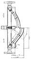
도 1은 본 발명을 적용한 코리올리 미터를 예시한 도면이며, 입구 배관 및 출구 배관을 수평으로 하여 장착했다고 가정하고, 그 정면에서 본 부분적 단면도(좌측도)와, 중앙부에서 절단한 측면도(우측도)이다.1 is a diagram illustrating a Coriolis meter to which the present invention is applied, assuming that the inlet pipe and the outlet pipe are mounted horizontally, a partial cross-sectional view (left side view) seen from the front side, and a side view (right side view) cut at the center portion. to be.
도 2는 아치형 튜브의 제원도이다.2 is a view of the arcuate tube.
도 3은 고정 아치를 나타낸 도면이다.3 is a view showing a fixed arch.
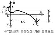
도 4는 수직 방향의 열팽창에 의한 모멘트도이다.4 is a moment diagram by thermal expansion in the vertical direction.
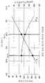
도 5는 직선 길이 L1을 변화시켰을 때의 최대 응력 σmax 및 튜브 높이 h를 나타낸 그래프이다.5 is a graph showing the maximum stress sigma max and the tube height h when the linear length L1 is changed.
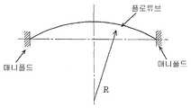
도 6은 중앙의 원호부와 그 양측의 직선부에 의해 구성되는 아치형 구성의 플로 튜브를 설명하기 위한 도면이다.It is a figure for demonstrating the flow tube of an arcuate structure comprised by the circular arc part of a center, and the linear part of both sides.
도 7은 종래의 아치형 구성의 플로 튜브를 가지는 코리올리 미터의 동작을 설명하기 위한 개념도이다.7 is a conceptual diagram for explaining the operation of a Coriolis meter having a flow tube of a conventional arcuate configuration.
도 8은 종래의 원호 구성의 플로 튜브를 설명하기 위한 도면이다.It is a figure for demonstrating the flow tube of the conventional circular arc structure.
도 9는 본 발명의 실시예의 형상을 중앙에서 우측에, 그리고 본 발명의 범위 밖의 비교예를 좌측에 대비하여 나타낸 도면이다.9 is a view showing the shape of an embodiment of the present invention from the center to the right and a comparative example outside the scope of the present invention against the left.
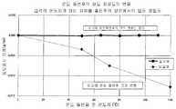
도 10은 실시예와 비교예에 대한 「온도 돌변 후의 밀도 정밀도의 변화」를 나타낸 도면이다.It is a figure which shows the "change of the density precision after temperature change" about an Example and a comparative example.
도 11은 치수비를 변화시켰을 때의 온도 돌변 후의 계기 오차 변화를 나타낸 도면이다.It is a figure which shows the change of the meter error after temperature change when the dimension ratio is changed.
도 12는 도 11의 「계기 오차 변화」에 대신하여, 「밀도 표시 변화」를 나타내는 동일한 실측 결과를 나타낸 도면이다.It is a figure which shows the same actual measurement result which shows "a density display change" instead of the "measurement error change" of FIG.
이하, 본 발명의 병렬 2개의 아치형 플로 튜브를 사용하는 아치형 튜브 타입 의 코리올리 미터를 예시에 따라 설명한다. 도 1은 본 발명을 적용한 코리올리 미터를 예시하는 도면이며, 입구 배관 및 출구 배관을 수평으로 하여 장착했다고 가정하고, 그 정면에서 본 부분적 단면도(좌측도)와, 중앙부에서 절단한 측면도(우측도)이다. 도시한 코리올리 미터는 사용에 있어서 수평 방향으로 장착하는 것 또는 수직 방향으로 장착하는 것 모두 가능하고, 또한 수평 방향으로 장착할 때도, 도 1에 나타낸 것과 같이 플로 튜브 중앙의 만곡(彎曲) 볼록부를 위로 하여 장착하는 것, 또는 반대로 아래로 하여 장착하는 것 모두 가능하다. 다만, 가스 계측의 경우에는 액체가 플로 튜브 중앙의 만곡 볼록부에 체류하지 않도록 만곡 볼록부를 도시한 것과 같이 위로 하는 것이 바람직하고, 또 반대로 액체 계측의 경우에는 기포가 체류하지 않도록 만곡 볼록부를 아래로 하여 장착하는 것이 요청된다.Hereinafter, an arcuate tube type Coriolis meter using two arcuate flow tubes of the present invention will be described according to an example. BRIEF DESCRIPTION OF THE DRAWINGS Fig. 1 is a diagram illustrating a Coriolis meter to which the present invention is applied, assuming that the inlet pipe and the outlet pipe are mounted horizontally, a partial cross-sectional view (left side view) seen from the front side and a side view (right side view) cut at the center portion. to be. The Coriolis meter shown can be mounted in the horizontal direction or in the vertical direction in use, and also when mounted in the horizontal direction, as shown in FIG. It can be mounted either by mounting it on the opposite side or vice versa. In the case of gas measurement, however, it is preferable that the curved convex part is upward so that the liquid does not stay in the curved convex part in the center of the flow tube.In contrast, in the case of liquid measurement, the curved convex part is lowered so that bubbles do not stay. To be mounted.
예시한 코리올리 미터의 플로 튜브(1, 2)는 아치형으로 만곡된 동일 형상의 유관(流管)이며, 각각의 양 단부는 입구측 및 출구측 매니폴드(25)에 용접 등에 의해 결합되어 있다. 그리고, 이하의 설명에 있어서, 측정 유체는 도 1의 좌측으로부터 유입되어 우측으로 유출된다고 가정하고 있다. 측정 유체는 플랜지(18)를 통해 접속되어 있는 외부 유관으로부터 유입되어 입구측 매니폴드에서 2개의 병렬 플로 튜브(1, 2)에 동일하게 분기된다. 그리고 플로 튜브(1, 2)의 출구측에서는 출구측 매니폴드(25)에서 합류되고, 플랜지(19)를 통해 접속되어 있는 외부 유관으로 유출된다.The
유입측과 유출측은 대칭으로 구성되어 있으므로, 도시한 유출측에 대하여 설명하면, 매니폴드(25)는 그 유출구[플랜지(19)와의 접속부]로부터 원호를 그리며 순조롭게 윗쪽의 소정 각도 방향으로 전향(轉向)되어, 플로 튜브(1, 2)와의 접속구에 이른다. 이와 같이, 매니폴드의 튜브 접속구를 튜브 상승 각도로 함으로써, 플로 튜브 자체는 단순히 한 방향으로 만곡시킬 뿐이며, 접속된 플로 튜브와 매니폴드는 전체로서 순조로운 아치형 형상을 구성한다. 또 매니폴드는 1개의 유출구로부터 2개의 병렬 플로 튜브(1, 2)로 분기되도록 2개의 유로를 형성한다.Since the inflow side and the outflow side are configured symmetrically, the outflow side shown will be described, and the manifold 25 smoothly turns in the upper predetermined angular direction by drawing an arc from the outlet (connection portion with the flange 19). And the connection port with the
이와 같이, 진동 측정을 위해 중요한 기능을 다하는 플로 튜브(1, 2) 자체는 한 방향으로 단순히 만곡시킨 구성을 가질 뿐이며, 유로를 2개의 병렬 플로 튜브로부터 외부 배관 방향으로 향하는 복잡한 유로 변경은 매니폴드로 대응하고 있다. 플로 튜브(1, 2)는 매니폴드와 용접 등에 의해 고착할 수 있어 가요부(可撓部)는 필요없고, 열 스트레스는 플로 튜브를 아치형 형상으로 함으로써 흡수하고, 또 배관 스트레스에도 강한 구조가 된다.As such, the
또 플로 튜브(1, 2)의 양단 근방에는 구동했을 때 진동의 경우 절부(節部)를 형성시키기 위한 기판(28)이 설치되고, 또한 이것은 플로 튜브(1, 2)가 병렬로 유지되도록 상호 고착되어 있다. 이 기판(28)은 이것을 구비할 때는 기판(28)에 의한 고착점이 진동의 제1 지점이 되는 동시에, 플로 튜브(1, 2)와 입구측 및 출구측 매니폴드(25)의 상단과의 결합단이 제2 지점이 되어 진동한다.In addition, near the both ends of the
구동 장치(15)는 아치형 플로 튜브의 중앙부에서, 구동 장치 코일이 한쪽의 플로 튜브(1)에, 구동 장치 마그넷이 다른 쪽의 플로 튜브(2)에 각각 장착 도구를 통해 장착되어 있다. 구동 장치 코일에의 배선은 플렉시블 프린트판(12)을 통해, 또한 배선 인출부(34)를 통해 이 코리올리 미터 외부에 접속된다. 배선 인출부(34)는 단면 반원 형상의 기초부(30)에 지지되는 동시에, 그것을 관통하고 있다. 이 기초부(30)에는 커버(31)가 일체로 접합되어, 매니폴드부의 칼라부(26)와 협동하고, 내부에 기밀 공간을 형성하고 있다. 한 쌍의 진동 검출 센서(16, 17)는 구동 장치(15)의 양측에서 한쪽의 플로 튜브(1)에 검출 센서 마그넷이, 다른 쪽의 플로 튜브(2)에 검출 센서 코일이 각각 장착 도구를 통해 장착되어 있다.As for the
동작에 있어서, 구동 장치(15)는 2개의 병렬 플로 튜브(1, 2)의 중앙부에서, 2개의 병렬 플로 튜브(1, 2)를 서로 반대 위상으로 공진 구동한다. 한 쌍의 진동 검출 센서(16, 17)는 구동 장치(15)의 장착 위치에 대하여 좌우 양측의 대칭 위치에 설치되어, 코리올리의 힘에 비례한 위상차를 검지한다. 그리고, 도시한 구동 장치(15) 및 한 쌍의 진동 검출 센서(16, 17)는 모두 플로 튜브(1)와 플로 튜브(2) 사이의 튜브축 사이에 배치되어 있다. 바꾸어 말하면, 도 1에 나타낸 것과 같이, 2개의 병렬 플로 튜브를 겹치는 방향으로 보았을 때, 구동 장치(15) 및 한 쌍의 진동 검출 센서(16, 17)의 각각을, 양 플로 튜브 사이에서, 또한 양 플로 튜브의 각각의 중심축을 잇는 선 상을 중심으로 하여 배치한 것이다. 이에 따라, 양 플로 튜브의 중심축을 잇는 선 상에서 구동력을 작용시키고, 또한 이 구동력에 따른 코리올리 힘를 검출할 수 있기 때문에, 진동 관성력에 의한 관성 모멘트가 생기지 않는다.In operation, the
온도 센서가 도시한 것과 같이, 2개소에 설치되어 있다. 플로 튜브 양측의 고정단(固定端) 간의 거리의 변동은 진동 주파수에 영향을 주므로, 보정할 필요가 있다. 도시한 장치는 이 보정을, 기초부(30)의 대표 온도를 계측함으로써, 그 신 장을 추측하여 실행하는 것이다. 또한, 플로 튜브의 매니폴드 결합단(結合端) 근처에서 온도를 측정하기 위한 센서가 구비된다. 이것은 플로 튜브의 온도가 변동됨으로써 강성(剛性)이 변동되는 것을 보정하기 위한 것이다.As shown by the temperature sensor, it is provided in two places. Since the fluctuation of the distance between the fixed ends on both sides of the flow tube affects the vibration frequency, it is necessary to correct it. The apparatus shown in figure performs this correction by guessing the extension length by measuring the representative temperature of the
도 1에 나타낸 아치형 구성의 플로 튜브는 중앙의 원호부와 그 양측의 직선부에 의해 구성되며, 입구 도관 및 출구 도관을 소정 상승 각도로 하고, 플로 튜브와 동일 방향으로 하여 결합되어 있다. 이와 같은 플로 튜브의 형상은 콤팩트하게 설계할 뿐만 아니라, 열영향에 대해서도 고려한 후 최적의 것으로 결정할 필요가 있다.The flow tube of the arcuate structure shown in FIG. 1 is comprised by the circular arc part of a center, and the straight part of both sides, It is combined by making an inlet conduit and an outlet conduit into a predetermined raise angle, and in the same direction as a flow tube. The shape of such a flow tube is not only designed to be compact, but also needs to be determined to be optimal after considering heat effects.
이하, 계측 유체가 온도 돌변을 일으켰을 때, 응력을 소정의 값으로 낮게 억제하고, 또한 가장 콤팩트하게 되도록 튜브 형상을 결정하는 방법을 도 2 내지 도 4를 참조하여 설명한다.Hereinafter, a method of determining the tube shape so as to suppress the stress to a predetermined value low and become the most compact when the measurement fluid causes a temperature change will be described with reference to FIGS. 2 to 4.
도 2에서, 플로 튜브의 입구측 및 출구측 매니폴드와의 접속점을 각각 C'점 및 C점, 그 중간의 플로 튜브 상의 천정점(天頂點)을 A점, 중앙의 원호부와 직선부와의 접속점을 B점으로 표시하고 있다. A점을 좌표 원점으로 하고, 거기에서 우방향으로 x축 정방향, 하방향으로 y축 정방향으로 하고 있다. 원호부의 원호 중심과 A점을 잇는 선을 기준으로 하여 원호형의 임의의 점까지의 각도를 φ, 원호부 단점(즉 B점)까지의 각도를 φ0, 원호부 반경을 R로 표시하고 있다. 또한, 플로 튜브의 높이를 h, C'점과 C점을 잇는 직선 길이(단점 간 직선 거리)의 반을 L/2, 이 직선과 플로 튜브의 직선부가 이루는 각도를 φ1로 표시하고 있다.In Fig. 2, the connection points with the inlet and outlet manifolds of the flow tube are respectively C 'and C points, and the ceiling point on the flow tube in the middle thereof is the A point, the circular arc part and the straight line part. The connection point is indicated by B point. A point is made into the coordinate origin, and it is set as the x-axis positive direction in the right direction, and the y-axis positive direction in the downward direction from there. The angle to an arbitrary point of the arc shape is represented by φ, the angle to the weak point of the arc portion (that is, the point B) is represented by
이와 같은 플로 튜브 형상의 결정 순서로서 플로 튜브의 단점 간 직선 거리 L과, 플로 튜브의 수직 방향 높이 h와의 비 h/L=1/3~1/4(0.33~0.25)로 한다. 본 발명은 전술한 관점으로부터 응력 분산, 내진성(耐震性)이 우수한 것으로 한 병렬 2개의 아치형 튜브 타입의 코리올리 미터를 전제로 하고 있다. 그리고, 통상, 종래의 만곡 관형의 플로 튜브는 h/L>1.3으로 구성되고, 또한 직관형의 플로 튜브는 당연히 h=0이며, h/L=0으로 구성되어 있다.As the flow tube shape determination procedure, the ratio h / L = 1/3 to 1/4 (0.33 to 0.25) between the straight line distance L between the disadvantages of the flow tube and the vertical height h of the flow tube is set. The present invention is based on the premise of two parallel arc-type coriolis meters having excellent stress dispersion and shock resistance from the above point of view. In general, a conventional curved tubular flow tube is composed of h / L> 1.3, and a straight flow tube is naturally composed of h = 0 and h / L = 0.
또한 형상 결정의 전제로서, 최대 유량에서의 매니폴드와 아치형 튜브를 포함하는 압력 손실을 1bar 이하로 하는 것을 목표로 한다(입구측 매니폴드의 조리개 효과와 출구측 매니폴드의 확대 효과에 의한 압력 손실 및 아치형 튜브 전체 길이를 등가 직관 길이로 한 압력 손실의 합계). 또 최대 유량에서의 2개의 튜브 센서 코일로부터의 사인파 출력의 시간 위상차를 6㎲ 이상으로 하는 것을 목표로 한다. 튜브의 고유 진동수를 상용 주파수보다 높은 250~400Hz로 설정한다.In addition, as a premise of the shape determination, the pressure loss including the manifold and the arcuate tube at the maximum flow rate is aimed at 1 bar or less (pressure loss due to the aperture effect of the inlet manifold and the expansion effect of the outlet manifold). And the sum of the pressure losses with the total length of the arcuate tube as the equivalent straight pipe length. Moreover, it aims at making the time phase difference of the sine wave output from two tube sensor coils at the maximum flow volume into 6 microseconds or more. Set the tube's natural frequency to 250-400 Hz, above normal frequency.
이상의 전제로부터, 튜브 내경 Di와 단점 간 직선 거리 L이 결정된다. 다음에, 이와 같이 하여 개략 결정된 아치형 튜브로 계측 유체의 돌변 온도에 의한 응력이 적은 형상의 상세를 구한다. 결론적으로는, 후술의 (24)식에 나타낸 것과 같이, 고정단에 발생하는 최대 응력을 구할 수 있다. 그리고, 이 최대 응력은 직선부의 길이 L1과 관련지어 구할 수 있기 때문에, 최대 응력이 작아지는 길이 L1과 함께, 튜브의 수직 방향 높이 h를 구할 수 있다. 이하, 이것에 대하여 상세하게 설명한다.From the above premise, the linear distance L between the tube inner diameter Di and the disadvantage is determined. Next, the arcuate tube roughly determined in this way obtains the detail of the shape with little stress by the sudden change temperature of a measurement fluid. In conclusion, as shown in Equation (24) below, the maximum stress occurring at the fixed end can be obtained. And since this maximum stress can be calculated | required in connection with the length L1 of a linear part, the vertical height h of a tube can be calculated | required with the length L1 in which a maximum stress becomes small. This will be described in detail below.
도 2에 나타낸 것과 같이, 도면 중 A점이 아치형 튜브의 천정점이며, A-B 사이가 원호 튜브(의 절반), B-C 사이가 직선 튜브이며, C점과 C'점은 고정되어 있 다. 튜브 연속의 조건으로부터 φ0=φ1로 한다. 지금 튜브의 내부를 흐르는 액체의 온도가 돌연 t1로부터 t2로 변화(돌변)되었을 때의 튜브에 발생하는 열응력을 구하지만, A점으로부터 y축 방향으로 d만큼 이동한 점, 즉 탄성 중심(열팽창에 의한 모멘트 0의 점)을 원점으로 취하여 해석한다. 이 탄성 중심을 원점으로 한 좌표를 (x1, y1)로 표현하고 있다. 즉, x1=x, y1=y-d이다.As shown in Fig. 2, point A is the ceiling point of the arcuate tube in the figure, between A-B is the arc tube (half of half), B-C is the straight tube, and C and C 'points are fixed. Let φ0 = φ1 from the conditions of tube continuation. The thermal stress generated in the tube when the temperature of the liquid flowing inside the tube is suddenly changed (turned) from t1 to t2 is calculated, but the point moved by the point d in the y-axis direction from the point A, that is, the elastic center (thermal expansion) Analyze the
티모셴코(Timoshenko)에 의하면, 도 3에 나타낸 것과 같은 고정 아치로 좌표의 원점을 A점으로부터 점 O로 이동하게 하고, 튜브 재료의 종탄성(縱彈性) 계수를 E, 튜브의 단면 2차 모멘트=π/64(Do4-Di4)를 I로 하면, 새로운 종좌표 y1=y-d가 다음의 조건According to Timoshenko, the origin of the coordinates is moved from point A to point O with a fixed arch as shown in Fig. 3, and the longitudinal modulus of the tube material is E, the cross-sectional secondary moment of the tube = If π / 64 (Do4 -Di4 ) is set to I, the new ordinate y1 = yd is given by

을 만족시키도록, 거리 d를 선택하면 d는 (2)식으로 표현된다.If the distance d is selected to satisfy d, d is expressed by (2).

먼저 최초에, 온도 돌변에 의한 x 방향의 팽창에 의한 탄성 왜곡 에너지 Ux를 고려한다. s: 아치(궁형)의 임의 위치에서의 길이, ds: 아치의 임의 위치에서의 미소 길이, U: 탄성 왜곡 에네지, Mx: X축 방향의 모멘트, My: Y축 방향의 모멘트, N: 튜브의 압축력,α: 튜브 재료의 온도 팽창 계수, t: 튜브의 온도 또는 온도차로 하고, 탄성 중심(0점)에서의 수평 방향의 힘인 압축력 Ho와 탄성 중심(O점)에 서의 굽힘 모멘트 Mo을 부정정량(不靜定量)으로 취하면 카스티글리아노(Castigliano)의 제2 정리(定理)로부터,First, the elastic distortion energy Ux due to the expansion in the x direction due to the temperature change is considered. s: length at any position of the arch, ds: minute length at any position of the arch, U: elastic distortion energy, Mx: moment in the X axis, My: moment in the Y axis, N: tube Compression force, α: coefficient of thermal expansion of the tube material, t: temperature of the tube or temperature difference, compressive force Ho which is the horizontal force at the elastic center (zero point) and bending moment Mo at the elastic center (o point) Is taken as an indeterminate quantity from the second theorem of Castigliano,


가 성립된다. 여기에Is established. Here

탄성 중심의 조건에 의해 Mo=0이기 때문에Because Mo = 0 due to the condition of the elastic center

이 얻어진다. (5), (6) 식에 의해 아치형 튜브의 임의 단면의 굽힘 모멘트와 압축력이 구해진다. 도 2에 나타낸 것과 같은 원호와 직선에 의한 아치형 튜브의 제원을 넣어 (2)식의 d를 풀면,Is obtained. The bending moment and the compressive force of an arbitrary cross section of the arcuate tube are obtained by the equations (5) and (6). When the specifications of the arcuate tube by a circular arc and a straight line as shown in FIG. 2 are put, and d of Formula (2) is solved,

여기서, R: 아치형 튜브의 원호 부분의 원호 반경이다.Where R is the arc radius of the arc part of the arcuate tube.
따라서 정점(頂点) A로부터 탄성 중심까지의 거리는Therefore, the distance from vertex A to the center of elasticity is

로 표현된다.It is expressed as
동일하게 하여 (6)식을 풀면If you solve the equation (6)

로 된다. 여기에서 It becomes From here


(5), (9), (10), (11)식에서 임의 튜브 단면의 굽힘 모멘트 및 압축력 N이 구해진다. 여기서, A: 튜브의 단면적=πㆍ(Do2-Di2)/4, Do: 튜브 외경, Di: 튜브 내경이다.The bending moment and the compressive force N of any tube cross section are obtained by the formulas (5), (9), (10) and (11). Here, A is the cross-sectional area of the tube = π · (Do2 -Di2 ) / 4, Do: tube outer diameter, Di: tube inner diameter.
다음에 열팽창에 의한 수직 방향에 관해서는 도 4와 같이, 부정정력(不靜定力)(redundant force)을 H1, 부정정 모멘트(redundant moment)를 M1로 하면 다음 식이 성립된다.Next, with respect to the vertical direction due to thermal expansion, as shown in FIG. 4, the following equation is established when the redundant force is set to H1 and the redundant moment is set to M1.

카스티글리아노의 제2 정리로부터, 탄성 왜곡 에네지를 Uy로 하면,From the second theorem of Castigliano, if the elastic distortion energy is Uy,

또In addition

이것으로부터From this

가 얻어진다. 여기에서Is obtained. From here


Mx도 My도 같은 방향이므로 가산되어 합성 모멘트 M은Mx and My are also in the same direction, so the composite moment M

로 된다. 또 최대 모멘트는 고정단 C에서의 값이며 이것을 Mmax로 하면 최대 굽힘 응력은It becomes The maximum moment is the value at the fixed end C. If this is Mmax, the maximum bending stress is

로 된다. 여기서 Z: 아치의 단면 계수=(π/32)ㆍ(Do4-Di4)/Do이다. 또 C점의 압축 응력은It becomes Where Z is the cross-sectional coefficient of the arch = (π / 32) · (Do4 -Di4 ) / Do. The compressive stress at point C

따라서 합응력(合應力)은Therefore, the combined stress

그리고, 계산의 결과, σC는 σMmax의 2~3%로 작아 무시할 수 있는 것을 알 수 있다. 즉,And as a result of calculation, it turns out that (sigma) C is small to 2-3% of (sigma) Mmax and can be ignored. In other words,

으로서 된다. 따라서 최대 응력은 고정단에 발생하여It becomes as. Therefore, the maximum stress occurs at the fixed end

로 표현된다.It is expressed as
예를 들면 구경 25mm이며 튜브 재료에 스테인리스제를 사용하여, 제원을 튜브 내경 Di=15mm, 튜브 두께 0.75mm로 하고 돌변 온도 110℃로 했을 때, 도 2의 기하학적 치수 형상으로부터,For example, when the diameter is 25 mm and stainless steel is used for the tube material, and the specifications are made into the tube inner diameter Di = 15 mm, the tube thickness 0.75 mm, and the protrusion temperature is 110 degreeC, from the geometrical dimension shape of FIG.


의 관계가 있으므로, L=371.4mm=일정으로 하고, φ1=φ0=40˚로 한 경우, 치수비 h/L을 변화시켰을 때의 최대 응력 σmax 및 튜브 높이 h를 그래프에 나타내면 도 5와 같이 된다. 도면으로부터 알 수 있듯이, 치수비 h/L≥0.31에서 최대 응력 σmax는 최소값(약 125N/㎟)에 수렴(收斂)된다. 그러나 치수비 h/L를 크게 취하면 h가 증대하므로 치수비 h/L=0.31로 취하면 최대 응력도 적고, 치수도 콤팩트하게 된다(도 5에서의 백색의 마크가 그 포인트임). 또 이 포인트로 결정한 것을, 도 9 및 도 10에서 「실시예」로서 나타내고 있다. 이와 같이, 이 포인트는 최적의 것이지만, 도 5에 보이는 것과 같이, 치수비 h/L=1/4~1/3의 범위이면, 최대 응력 σmax는 사실상 최소치에 가까운 한편, 튜브 높이 h에 대해서도 충분히 낮아, 콤팩트하게 구성하는 것이 가능해진다. 치수비 h/L을 작게 하면, 최대 응력은 증가하지만, h/L=1/3 시의 응력값을 σmin으로 하면, h/L≥1/4이면 1.3 σmin 이하로 억제할 수 있다.Since L = 371.4mm = constant and φ1 = φ0 = 40 °, the maximum stress σmax and tube height h when the dimensional ratio h / L is changed are shown in FIG. 5. . As can be seen from the figure, the maximum stress sigma max at the dimensional ratio h / L ≧ 0.31 converges to the minimum value (about 125 N / mm 2). However, when the dimension ratio h / L is made large, h increases, so when the dimension ratio h / L = 0.31 is used, the maximum stress is small and the dimension is also compact (the white mark in Fig. 5 is the point). In addition, what was determined by this point is shown as an "Example" in FIG. 9 and FIG. Thus, although this point is optimal, as shown in Fig. 5, if the ratio of the ratio h / L = 1/4 to 1/3 is obtained, the maximum stress sigma is substantially close to the minimum value, while the tube height h is sufficient. It becomes low and can be comprised compactly. If the dimension ratio h / L is made small, the maximum stress will increase, but if the stress value at h / L = 1/3 is sigma min, it can be suppressed to 1.3 sigma min or less if h / L ≧ 1/4.
도 9는 본 발명의 실시예(L1=130mm, h=115mm, h/L=0.31)의 형상을 중앙에서 우측에, 그리고 본 발명의 범위 밖의 비교예(L1-20mm, h=75mm, h/L=1/5)를 좌측에 대비하여 나타낸 도면이다.9 shows the shape of an embodiment of the present invention (L1 = 130mm, h = 115mm, h / L = 0.31) from the center to the right side and the comparative example outside the scope of the present invention (L1-20mm, h = 75mm, h / L = 1/5) is shown in the left side.
도 10은 상기 실시예와 비교예에 대한 「온도 돌변 후의 밀도 정밀도의 변화」를 나타낸 도면이다. 이것은 유체 온도를 그래프 횡축에 나타낸 온도차로 급격하게 변화시킨(돌변) 후, 재차 상온으로 되돌려 밀도 정밀도를 측정한 결과를 나타내고 있다. 도시한 것과 같이, 실시예는 큰 온도차로 급격하게 변화해도, 측정한 밀도 정밀도에 오차는 생기지 않는데 대하여, 비교예는 돌변 온도가 커지는 데 따 라, 밀도 표시 오차가 증가하고 있다.It is a figure which shows the "change of the density precision after temperature change" about the said Example and a comparative example. This shows the result of measuring the density accuracy by returning the fluid temperature rapidly to the temperature difference indicated on the graph horizontal axis (turning) and then returning to normal temperature again. As shown in the drawing, even if the Example suddenly changes due to a large temperature difference, no error occurs in the measured density accuracy. In the Comparative Example, the density display error increases as the temperature increases.
도 11은 치수비를 변화시켰을 때의 온도 돌변 후의 계기 오차 변화를 나타낸 도면이다. 도면 중, 우측란 밖에 나타낸 치수를 가지는 유량계에 대하여, 실측에 의해 구한 데이터이다. 유량계를 사용할 때 온도 돌변이 행해지는 상황으로서 세정(스팀 세정) 시에 플로 튜브 온도가 130℃ 정도까지 급격하게 상승되어, 상온을 20℃로 하면 최대 110℃의 온도차인 온도 돌변이 고려된다. 이상을 상정하여 110℃ 온도차를 부하하는 실험을 실행했다. 실험의 결과로서는, 1/4≤h/L≤1/3의 범위에서 제작된 것은 온도 돌변 후의 계기 오차 변화는 거의 없고, 1/4≤h/L≤1/3의 범위 밖인 h/L=1/5로 제작된 것은 ―0.2% 이상의 계기 오차 변화가 보였다. 코리올리 유량계로서 ―0.2%의 계기 오차 변화는 커 유량계의 보증 정밀도로부터 벗어나 버린다(일반적인 코리올리 질량 유량계의 계기 오차 정밀도는 ±0.2% 정도).It is a figure which shows the change of the meter error after temperature change when the dimension ratio is changed. In the figure, it is the data calculated | required by actual measurement about the flowmeter which has the dimension shown outside the right column. As a situation where the temperature fluctuation is performed when the flowmeter is used, the flow tube temperature rapidly rises to about 130 ° C. during washing (steam washing), and when the normal temperature is 20 ° C., the temperature fluctuation which is a temperature difference of up to 110 ° C. is considered. Assuming the above, the experiment which loads 110 degreeC temperature difference was performed. As a result of the experiment, the one manufactured in the range of 1/4? H / L? 1/3 has almost no change in the instrument error after the temperature change, and h / L = outside the range of 1/4? H / L? The one-fifth produced showed a change in instrument error of more than -0.2%. As a Coriolis flowmeter, the change in instrument error of -0.2% is large and deviates from the guarantee accuracy of the flowmeter (the instrument error precision of a typical Coriolis mass flowmeter is about ± 0.2%).
도 12는 도 11의 「계기 오차 변화」에 대신하여 「밀도 표시 변화」를 표시하는 동일한 실측 결과를 나타낸 도면이다. 도 11과 동일한 경향이 얻어지고 있다. h/L=1/5로 제작된 것은 밀도 표시값에서도 변화량이 커 보증 정밀도로부터 벗어난다(밀도계로서의 일반적인 보증 정밀도는 ±0.002g/ml 정도).It is a figure which shows the same actual measurement result which displays "a density display change" instead of the "measurement error change" of FIG. The same tendency as in FIG. 11 is obtained. The one produced at h / L = 1/5 deviates from the guarantee accuracy even in the density display value (the general guarantee accuracy as a density meter is about ± 0.002 g / ml).
도 11 및 도 12에 나타낸 것과 같은 실측 결과에 따라, h/L이 1/4 이하로 되면 계기 오차 변화 및 밀도 표시값이 급격하게 변화되는 것을 확인할 수 있었다. h/L=1/5의 것은 온도 돌변에 의해 플로 튜브 응력이 탄성 한계를 넘어 소성(塑性) 변형을 일으키고, 플로 튜브의 기계적 특성의 변화에 따라 플로 튜브 주기가 변화됨으로써, 계기 오차 변화 및 밀도 표시값 변화가 발생된 것으로 추정할 수 있다.According to the measurement results as shown in FIG. 11 and FIG. 12, it was confirmed that when the h / L becomes 1/4 or less, the change in the meter error and the density display value changed drastically. In the case of h / L = 1/5, the flow tube stress exceeds the elastic limit and causes plastic deformation due to temperature change, and the flow tube cycle is changed according to the change in the mechanical characteristics of the flow tube. It can be estimated that the display value change has occurred.
본 발명에 의하면, 계측 유체가 온도 돌변을 일으켰을 때, 응력을 소정의 값으로 낮게 억제하고, 또한 가장 콤팩트하게 되도록 튜브 형상을 결정하는 것이 가능하게 된다.According to the present invention, when the measurement fluid causes a temperature change, the tube shape can be determined so as to suppress the stress to a predetermined value low and to be the most compact.
또 본 발명에 의하면, 플로 튜브를 원호 세그먼트와 직선 세그먼트로 구성한 병렬 2개의 아치형 튜브 타입이기 때문에 응력 분산, 내진성이 우수하다.Moreover, according to this invention, since it is a parallel two arc-shaped tube type which comprised the flow tube by the circular arc segment and the straight segment, it is excellent in stress dispersion and vibration resistance.
Claims (5)
Translated fromKoreanApplications Claiming Priority (5)
| Application Number | Priority Date | Filing Date | Title |
|---|---|---|---|
| JPJP-P-2001-00288260 | 2001-09-21 | ||
| JP2001288260AJP3593513B2 (en) | 2001-09-21 | 2001-09-21 | Bow-shaped coriolis meter and method for determining its shape |
| JP2001383936AJP3645855B2 (en) | 2001-12-18 | 2001-12-18 | Arcuate Coriolis Meter and Shape Determination Method |
| JPJP-P-2001-00383936 | 2001-12-18 | ||
| PCT/JP2002/006315WO2003029761A1 (en) | 2001-09-21 | 2002-06-25 | Arch-shaped tube type coriolis meter and method of determining shape of the coriolis meter |
Publications (2)
| Publication Number | Publication Date |
|---|---|
| KR20030044075A KR20030044075A (en) | 2003-06-02 |
| KR100541347B1true KR100541347B1 (en) | 2006-01-11 |
Family
ID=26622655
Family Applications (1)
| Application Number | Title | Priority Date | Filing Date |
|---|---|---|---|
| KR1020037006225AExpired - Fee RelatedKR100541347B1 (en) | 2001-09-21 | 2002-06-25 | Arch tube type Coriolis meter and its shape determination method |
Country Status (7)
| Country | Link |
|---|---|
| US (1) | US6802224B2 (en) |
| EP (1) | EP1429119A4 (en) |
| KR (1) | KR100541347B1 (en) |
| CN (1) | CN1245610C (en) |
| CA (1) | CA2428495C (en) |
| TW (1) | TW565683B (en) |
| WO (1) | WO2003029761A1 (en) |
Families Citing this family (34)
| Publication number | Priority date | Publication date | Assignee | Title |
|---|---|---|---|---|
| WO2003021202A1 (en)* | 2001-08-29 | 2003-03-13 | Endress + Hauser Flowtec Ag | Vibrational-type measuring sensor |
| WO2005010470A2 (en)* | 2003-07-15 | 2005-02-03 | Cidra Corporation | An apparatus and method for compensating a coriolis meter |
| US7134320B2 (en)* | 2003-07-15 | 2006-11-14 | Cidra Corporation | Apparatus and method for providing a density measurement augmented for entrained gas |
| US7299705B2 (en)* | 2003-07-15 | 2007-11-27 | Cidra Corporation | Apparatus and method for augmenting a Coriolis meter |
| US7698938B2 (en)* | 2004-06-10 | 2010-04-20 | Yamatake Corporation | Flowmeter having a bent inlet passage for constant flow-velocity distribution |
| WO2006112878A2 (en) | 2004-09-16 | 2006-10-26 | Cidra Corporation | Apparatus and method for providing a fluid cut measurement of a multi-liquid mixture compensated for entrained gas |
| DE102004053883A1 (en)* | 2004-11-04 | 2006-05-11 | Endress + Hauser Flowtec Ag | Vibration-type fluid flow sensor has casing and supports forming external vibrator and bypass sensor tube with laterally vibrating exciter and sensor |
| US7216549B2 (en) | 2004-11-04 | 2007-05-15 | Endress + Hauser Flowtec Ag | Vibration-type measurement transducer |
| CN101084416B (en)* | 2004-11-04 | 2010-06-16 | 恩德斯+豪斯流量技术股份有限公司 | Vibration-type measuring transducer |
| US7389687B2 (en) | 2004-11-05 | 2008-06-24 | Cidra Corporation | System for measuring a parameter of an aerated multi-phase mixture flowing in a pipe |
| US7350421B2 (en)* | 2004-12-13 | 2008-04-01 | Endress + Hauser Flowtec Ag | Vibratory measurement transducer |
| DE102004060115A1 (en)* | 2004-12-13 | 2006-06-14 | Endress + Hauser Flowtec Ag | Transducer of the vibration type |
| KR20130022427A (en)* | 2005-04-06 | 2013-03-06 | 마이크로 모우션, 인코포레이티드 | Compact vibratory flowmeter for measuring flow characteristics of a multi-phase flow material |
| EP1869415B1 (en) | 2005-04-06 | 2018-01-10 | Micro Motion, Inc. | Compact vibratory flowmeter for measuring flow characteristics of a cement flow material |
| US7325461B2 (en) | 2005-12-08 | 2008-02-05 | Endress + Hauser Flowtec Ag | Measurement transducer of vibration-type |
| KR101231108B1 (en)* | 2008-05-01 | 2013-02-07 | 마이크로 모우션, 인코포레이티드 | Very low frequency vibratory flow meter and method of forming and operating the same |
| DE102009028007A1 (en)* | 2009-07-24 | 2011-01-27 | Endress + Hauser Flowtec Ag | Measuring transducer of the vibration type and measuring device with such a transducer |
| US8404076B2 (en)* | 2010-02-12 | 2013-03-26 | Malema Engineering Corporation | Methods of manufacturing and temperature calibrating a coriolis mass flow rate sensor |
| JP2011180151A (en)* | 2011-05-19 | 2011-09-15 | Micro Motion Inc | Small oscillating flowmeter for measuring fluidity of multi-phase flow material |
| JP2013079984A (en)* | 2013-02-04 | 2013-05-02 | Micro Motion Inc | Small oscillating flow-meter for measuring flow quantity of multi-phase flow material |
| CN104776891A (en)* | 2015-03-12 | 2015-07-15 | 孙晓君 | Mass flow rate sensor |
| DE102015109790B4 (en)* | 2015-06-18 | 2025-08-14 | Endress + Hauser Flowtec Ag | Coriolis mass flow meter and/or density meter |
| AU2016361419A1 (en)* | 2015-11-24 | 2018-07-05 | Malema Engineering Corporation | Integrated coriolis mass flow meters |
| JP2018536863A (en)* | 2015-12-11 | 2018-12-13 | マイクロ モーション インコーポレイテッド | Asymmetric flow meter and associated method |
| EP3495784A1 (en) | 2017-12-07 | 2019-06-12 | Heinrichs Messtechnik GmbH | Coriolis mass flow meter |
| DE202017006709U1 (en) | 2017-12-07 | 2018-02-12 | Heinrichs Messtechnik Gmbh | Coriolis mass flowmeter |
| USD863088S1 (en) | 2017-12-08 | 2019-10-15 | Heinrichs Messtechnik Gmbh | Flow checking apparatus |
| AT522357B1 (en)* | 2019-03-18 | 2020-11-15 | Avl List Gmbh | Measuring system for measuring a mass flow rate, a density, a temperature and / or a flow rate |
| CN110793584B (en)* | 2019-11-13 | 2021-02-09 | 四川奥达测控装置有限公司 | Multiphase flow mass flow measurement system and measurement method |
| DE102019135303B4 (en)* | 2019-12-19 | 2024-03-14 | Endress + Hauser Flowtec Ag | Measuring sensor of a measuring device for detecting a mass flow, a viscosity, a density and/or a size derived therefrom of a flowable medium |
| US11619532B2 (en) | 2020-04-10 | 2023-04-04 | Malema Engineering Corporation | Replaceable, gamma sterilizable Coriolis flow sensors |
| US11300435B2 (en) | 2020-04-10 | 2022-04-12 | Malema Engineering Corporation | Coriolis mass flow sensors having different resonant frequencies |
| DE102020121677A1 (en) | 2020-08-18 | 2022-02-24 | Endress+Hauser Flowtec Ag | Flow measurement arrangement |
| US12372390B2 (en) | 2023-05-08 | 2025-07-29 | Malema Engineering Corporation | Coriolis mass flow rate sensor |
Family Cites Families (5)
| Publication number | Priority date | Publication date | Assignee | Title |
|---|---|---|---|---|
| US5796011A (en) | 1993-07-20 | 1998-08-18 | Endress + Hauser Flowtech Ag | Coriolis-type mass flow sensor |
| JP3656947B2 (en) | 1999-10-05 | 2005-06-08 | 株式会社オーバル | Coriolis mass flow meter |
| JP3428563B2 (en) | 2000-04-26 | 2003-07-22 | 株式会社オーバル | Coriolis mass flowmeter |
| US6711958B2 (en) | 2000-05-12 | 2004-03-30 | Endress + Hauser Flowtec Ag | Coriolis mass flow rate/density/viscoy sensor with two bent measuring tubes |
| EP1154243B1 (en)* | 2000-05-12 | 2006-12-20 | Endress + Hauser Flowtec AG | Coriolis mass flow measurement device with two curved measurement conduits |
- 2002
- 2002-06-25KRKR1020037006225Apatent/KR100541347B1/ennot_activeExpired - Fee Related
- 2002-06-25WOPCT/JP2002/006315patent/WO2003029761A1/enactiveIP Right Grant
- 2002-06-25CNCNB028033515Apatent/CN1245610C/ennot_activeExpired - Fee Related
- 2002-06-25EPEP02743713Apatent/EP1429119A4/ennot_activeWithdrawn
- 2002-06-25USUS10/415,257patent/US6802224B2/ennot_activeExpired - Fee Related
- 2002-06-25CACA002428495Apatent/CA2428495C/ennot_activeExpired - Fee Related
- 2002-07-02TWTW091114653Apatent/TW565683B/ennot_activeIP Right Cessation
Also Published As
| Publication number | Publication date |
|---|---|
| KR20030044075A (en) | 2003-06-02 |
| CA2428495A1 (en) | 2003-04-10 |
| EP1429119A4 (en) | 2006-05-17 |
| CN1483138A (en) | 2004-03-17 |
| US20040040387A1 (en) | 2004-03-04 |
| US6802224B2 (en) | 2004-10-12 |
| EP1429119A1 (en) | 2004-06-16 |
| CA2428495C (en) | 2007-07-10 |
| TW565683B (en) | 2003-12-11 |
| CN1245610C (en) | 2006-03-15 |
| WO2003029761A1 (en) | 2003-04-10 |
Similar Documents
| Publication | Publication Date | Title |
|---|---|---|
| KR100541347B1 (en) | Arch tube type Coriolis meter and its shape determination method | |
| KR100327557B1 (en) | Coriolis mass flowmeter | |
| JP3656947B2 (en) | Coriolis mass flow meter | |
| US5357811A (en) | Single tube coriolis flow meter with floating intermediate section | |
| WO2004099733A1 (en) | Coriolis flowmeter | |
| KR100340673B1 (en) | Coriolis mass flowmeter and manufacturing method thereof | |
| JP3782421B2 (en) | Coriolis flow meter | |
| KR100877464B1 (en) | 3rd Mode Vibratory Coriolis Flowmeter | |
| JP3782422B2 (en) | Coriolis flow meter | |
| JP3645855B2 (en) | Arcuate Coriolis Meter and Shape Determination Method | |
| JP3593513B2 (en) | Bow-shaped coriolis meter and method for determining its shape | |
| JP2939242B1 (en) | Coriolis mass flowmeter | |
| JP3782438B1 (en) | Coriolis flow meter with double-loop flow tube | |
| JP2001108501A (en) | Coriolis mass flowmeter | |
| JP7328832B2 (en) | coriolis flow meter | |
| JPH11166846A (en) | Coriolis mass flowmeter |
Legal Events
| Date | Code | Title | Description |
|---|---|---|---|
| A201 | Request for examination | ||
| PA0105 | International application | St.27 status event code:A-0-1-A10-A15-nap-PA0105 | |
| PA0201 | Request for examination | St.27 status event code:A-1-2-D10-D11-exm-PA0201 | |
| PG1501 | Laying open of application | St.27 status event code:A-1-1-Q10-Q12-nap-PG1501 | |
| PN2301 | Change of applicant | St.27 status event code:A-3-3-R10-R13-asn-PN2301 St.27 status event code:A-3-3-R10-R11-asn-PN2301 | |
| E902 | Notification of reason for refusal | ||
| PE0902 | Notice of grounds for rejection | St.27 status event code:A-1-2-D10-D21-exm-PE0902 | |
| P11-X000 | Amendment of application requested | St.27 status event code:A-2-2-P10-P11-nap-X000 | |
| P13-X000 | Application amended | St.27 status event code:A-2-2-P10-P13-nap-X000 | |
| E701 | Decision to grant or registration of patent right | ||
| PE0701 | Decision of registration | St.27 status event code:A-1-2-D10-D22-exm-PE0701 | |
| GRNT | Written decision to grant | ||
| PR0701 | Registration of establishment | St.27 status event code:A-2-4-F10-F11-exm-PR0701 | |
| PR1002 | Payment of registration fee | St.27 status event code:A-2-2-U10-U12-oth-PR1002 Fee payment year number:1 | |
| PG1601 | Publication of registration | St.27 status event code:A-4-4-Q10-Q13-nap-PG1601 | |
| PR1001 | Payment of annual fee | St.27 status event code:A-4-4-U10-U11-oth-PR1001 Fee payment year number:4 | |
| PR1001 | Payment of annual fee | St.27 status event code:A-4-4-U10-U11-oth-PR1001 Fee payment year number:5 | |
| PR1001 | Payment of annual fee | St.27 status event code:A-4-4-U10-U11-oth-PR1001 Fee payment year number:6 | |
| PR1001 | Payment of annual fee | St.27 status event code:A-4-4-U10-U11-oth-PR1001 Fee payment year number:7 | |
| FPAY | Annual fee payment | Payment date:20121130 Year of fee payment:8 | |
| PR1001 | Payment of annual fee | St.27 status event code:A-4-4-U10-U11-oth-PR1001 Fee payment year number:8 | |
| FPAY | Annual fee payment | Payment date:20131218 Year of fee payment:9 | |
| PR1001 | Payment of annual fee | St.27 status event code:A-4-4-U10-U11-oth-PR1001 Fee payment year number:9 | |
| LAPS | Lapse due to unpaid annual fee | ||
| PC1903 | Unpaid annual fee | St.27 status event code:A-4-4-U10-U13-oth-PC1903 Not in force date:20141230 Payment event data comment text:Termination Category : DEFAULT_OF_REGISTRATION_FEE | |
| PC1903 | Unpaid annual fee | St.27 status event code:N-4-6-H10-H13-oth-PC1903 Ip right cessation event data comment text:Termination Category : DEFAULT_OF_REGISTRATION_FEE Not in force date:20141230 |