KR100516853B1 - Combination structure of focusing terminal and escape coil and small rotating electric motor and vehicle alternator using it - Google Patents
Combination structure of focusing terminal and escape coil and small rotating electric motor and vehicle alternator using itDownload PDFInfo
- Publication number
- KR100516853B1 KR100516853B1KR1019970024432AKR19970024432AKR100516853B1KR 100516853 B1KR100516853 B1KR 100516853B1KR 1019970024432 AKR1019970024432 AKR 1019970024432AKR 19970024432 AKR19970024432 AKR 19970024432AKR 100516853 B1KR100516853 B1KR 100516853B1
- Authority
- KR
- South Korea
- Prior art keywords
- coil
- coils
- focusing terminal
- derivation
- terminal
- Prior art date
- Legal status (The legal status is an assumption and is not a legal conclusion. Google has not performed a legal analysis and makes no representation as to the accuracy of the status listed.)
- Expired - Fee Related
Links
Images


Classifications
- H—ELECTRICITY
- H01—ELECTRIC ELEMENTS
- H01R—ELECTRICALLY-CONDUCTIVE CONNECTIONS; STRUCTURAL ASSOCIATIONS OF A PLURALITY OF MUTUALLY-INSULATED ELECTRICAL CONNECTING ELEMENTS; COUPLING DEVICES; CURRENT COLLECTORS
- H01R4/00—Electrically-conductive connections between two or more conductive members in direct contact, i.e. touching one another; Means for effecting or maintaining such contact; Electrically-conductive connections having two or more spaced connecting locations for conductors and using contact members penetrating insulation
- H01R4/10—Electrically-conductive connections between two or more conductive members in direct contact, i.e. touching one another; Means for effecting or maintaining such contact; Electrically-conductive connections having two or more spaced connecting locations for conductors and using contact members penetrating insulation effected solely by twisting, wrapping, bending, crimping, or other permanent deformation
- H01R4/18—Electrically-conductive connections between two or more conductive members in direct contact, i.e. touching one another; Means for effecting or maintaining such contact; Electrically-conductive connections having two or more spaced connecting locations for conductors and using contact members penetrating insulation effected solely by twisting, wrapping, bending, crimping, or other permanent deformation by crimping
- H01R4/183—Electrically-conductive connections between two or more conductive members in direct contact, i.e. touching one another; Means for effecting or maintaining such contact; Electrically-conductive connections having two or more spaced connecting locations for conductors and using contact members penetrating insulation effected solely by twisting, wrapping, bending, crimping, or other permanent deformation by crimping for cylindrical elongated bodies, e.g. cables having circular cross-section
- H—ELECTRICITY
- H02—GENERATION; CONVERSION OR DISTRIBUTION OF ELECTRIC POWER
- H02K—DYNAMO-ELECTRIC MACHINES
- H02K15/00—Processes or apparatus specially adapted for manufacturing, assembling, maintaining or repairing of dynamo-electric machines
- H02K15/30—Manufacture of winding connections
- H02K15/33—Connecting winding sections; Forming leads; Connecting leads to terminals
- H—ELECTRICITY
- H01—ELECTRIC ELEMENTS
- H01R—ELECTRICALLY-CONDUCTIVE CONNECTIONS; STRUCTURAL ASSOCIATIONS OF A PLURALITY OF MUTUALLY-INSULATED ELECTRICAL CONNECTING ELEMENTS; COUPLING DEVICES; CURRENT COLLECTORS
- H01R43/00—Apparatus or processes specially adapted for manufacturing, assembling, maintaining, or repairing of line connectors or current collectors or for joining electric conductors
- H01R43/04—Apparatus or processes specially adapted for manufacturing, assembling, maintaining, or repairing of line connectors or current collectors or for joining electric conductors for forming connections by deformation, e.g. crimping tool
- H01R43/058—Crimping mandrels
- H—ELECTRICITY
- H02—GENERATION; CONVERSION OR DISTRIBUTION OF ELECTRIC POWER
- H02K—DYNAMO-ELECTRIC MACHINES
- H02K11/00—Structural association of dynamo-electric machines with electric components or with devices for shielding, monitoring or protection
- H02K11/40—Structural association with grounding devices
- H—ELECTRICITY
- H02—GENERATION; CONVERSION OR DISTRIBUTION OF ELECTRIC POWER
- H02K—DYNAMO-ELECTRIC MACHINES
- H02K15/00—Processes or apparatus specially adapted for manufacturing, assembling, maintaining or repairing of dynamo-electric machines
- H02K15/30—Manufacture of winding connections
- H—ELECTRICITY
- H02—GENERATION; CONVERSION OR DISTRIBUTION OF ELECTRIC POWER
- H02K—DYNAMO-ELECTRIC MACHINES
- H02K3/00—Details of windings
- H02K3/04—Windings characterised by the conductor shape, form or construction, e.g. with bar conductors
Landscapes
- Engineering & Computer Science (AREA)
- Power Engineering (AREA)
- Manufacturing & Machinery (AREA)
- Windings For Motors And Generators (AREA)
- Insulation, Fastening Of Motor, Generator Windings (AREA)
- Synchronous Machinery (AREA)
Abstract
Translated fromKoreanDescription
Translated fromKorean본 발명은 전기기기의 복수개의 리드선을 묶어 인출하기에 적합한 집속단자와 도출코일의 결합구조 및 그것을 이용한 소형 회전전기와 차량용 교류발전기에 관한 것이다.The present invention relates to a coupling structure of a focusing terminal and a drawing coil suitable for bundling and drawing a plurality of lead wires of an electric machine, and a small rotary electric machine and a vehicle alternator using the same.
종래 전기기기의 에나멜피복리드선을 복수개 묶어 그것을 도체접합면측에 인(P)이 들어있는 납재를 납땜한 접합단자를 거쳐 인출하는 기술은 예를 들어 일본국 특개평 2-137306호 공보에서 알려져 있다. 이와 같은 기술은 도출코일세트를 납재를 거쳐 접합단자에 끼워넣고, 그 접합단자를 외부로부터 전기가열하면서 압접고정하는 것이었다.BACKGROUND ART Conventionally, a technique of bundling a plurality of enamel coated lead wires of an electric device and drawing them through a joint terminal for soldering a brazing filler metal containing phosphorus (P) on the conductor bonding surface side is known from, for example, Japanese Patent Laid-Open No. 2-137306. Such a technique was to insert a set of lead coils into a joint terminal through a brazing material, and to press-fit the joint terminal while electric heating from the outside.
또 일본국 특공평 7-32555호 공보에는 차량용 교류발전기의 고정자에 있어서, 복수개의 각 상의 중심측 도출단자를 접속고정구를 이용하여 일괄 결합하는 구조가 나타나 있고, 그 결합수단으로는 용접 또는 납땜 등이 이용되고 있는 것이 개시되어 있다.Japanese Unexamined Patent Application Publication No. 7-32555 discloses a structure in which a stator of a vehicle alternator is collectively coupled to a plurality of center-side lead terminals of each phase by using a connection fastener, and the coupling means includes welding or soldering. It is disclosed that this is used.
상기한 전자의 종래기술에서는 도출코일세트를 납재를 거쳐 접합단자에 끼워 넣고, 그 접합단자를 외부로부터 전기가열하면서 압접고정하는 것이기 때문에 높은 접합강도 및 내열성을 가지며, 또한 절연피막 그대로 일괄접합을 할 수 있는 이점이 있으나, 도출코일인 에나멜피복도선은 2개세트인 것 밖에 고려되어 있지 않아, 3개 이상의 도출코일세트인 경우에는 각각의 도출코일은 반드시 접합단자와 결합하는 것은 아니어서, 진동이 가해지면 접합되어 있지 않은 코일이 빠질 뿐만 아니라 주위의 결합력도 약해지게 되어 반드시 신뢰성이 높은 접속단자로는 되지 않는다.In the above-described conventional art, the lead coil set is inserted into a joint terminal through a brazing material, and the joint terminal is fixed by pressure welding while being electrically heated from the outside. Although there is an advantage in that the enamel coated lead wire, which is a derived coil, is considered to be only two sets, in the case of three or more derived coil sets, each derived coil is not necessarily combined with a junction terminal, so that vibration When applied, not only uncoiled coils are pulled out, but also the coupling force around them is weakened, and it is not necessarily a highly reliable connection terminal.
또 후자의 종래기술에서는 복수개의 각 상의 중심측 도출단을 접속고정구를 이용하여 일괄하고, 용접 또는 납땜 등으로 결합하는 구조를 개시하고 있으나, 도출단은 단지 정리되어 가열접속되어 있을 뿐이기 때문에 도출코일이 반드시 접속고정구에 강고하게 고착되어 있다고도 한정하지 않고, 또 도출코일끼리도 반드시 고착되어 있다고도 한정하지 않는다. 따라서 엔진룸에 장착되는 차량용 교류발전기의 중성점부에 이용된 경우에 상기와 같이 어느 한 개소라도 고착되지 않는 개소가 발생하면, 진동 등에 의하여 결합박리가 조장되고, 도전불량 때문에 신뢰성이 낮은 제품이 된다.In addition, the latter conventional technique discloses a structure in which a plurality of center side leading ends of respective phases are collectively connected by using a connecting fixture and welded or soldered, or the like, but the leading ends are simply arranged and heated and connected. The coils are not necessarily necessarily firmly fixed to the connection fixtures, nor are the coils necessarily adhered to each other. Therefore, when used in the neutral point of the vehicle alternator installed in the engine room, if any one of the locations does not stick as described above, the separation is encouraged by vibration, etc., and the product is low in reliability due to poor conductivity. .
본 발명의 목적 중의 하나는 결합력이 안정되고 신뢰성이 높은 집속단자와 도출코일의 결합구조를 제공하는 데 있다.One of the objectives of the present invention is to provide a coupling structure of a focusing terminal and a derivation coil having a stable coupling force and high reliability.
본 발명의 또다른 목적은 결합력이 안정되고 신뢰성이 높은 집속단자와 도출코일의 결합구조를 가지는 소형 회전전기 또는 차량용 교류발전기를 제공하는 데 있다.Still another object of the present invention is to provide a small rotary electric vehicle or an alternator for a vehicle having a coupling structure of a stable coupling force and a highly reliable focusing terminal and a drawing coil.
본 발명의 목적은, 적어도 3개이상으로 이루어지는 복수개의 도출코일을 묶은 코일세트와 집속단자의 결합구조에 있어서, 상기 도출코일세트의 각각의 도출코일은 코일주위의 일부가 적어도 상기 집속단자에 접촉하여 접합되어 있고, 상기 도출코일은 복수단(段)으로 정렬하여 겹쳐져 있고, 상기 집속단자는, 상기 도출코일을 접합한 후, 대면하는 1쌍의 평편한 부분과 그 폭방향 측부에 형성된 1쌍의 만곡부를 구비하고, 상기 대면하는 1쌍의 평편한 부분의 간격은, 상기 도출코일의 직경을 상기 코일의 겹쳐진 단(段)수와 곱한 값보다 작게 구성되며, 상기 집속단자는, 통전저항가열을 행함으로써, 납재를 개재하여 상기 각각의 도출코일과의 사이에서 전기적 및 기계적으로 결합되어 있고, 상기 도출코일의 피복 중 상기 집속단자와 상기 납재를 개재하여 접촉되어 있는 부분의 피복은, 탄화하여 상기 집속단자의 외측에 배출되어 있는 것을 특징으로 하는 집속단자와 도출코일의 결합구조에 의하여 달성된다.SUMMARY OF THE INVENTION An object of the present invention is a coupling structure of a coil set and a focusing terminal which bundles a plurality of lead coils consisting of at least three, wherein each of the guide coils of the derived coil set has at least a portion of the coil surrounding the at least one focusing terminal. And the lead coils are arranged in a plurality of stages to overlap each other, and the focusing terminal is formed by joining the pair of flat portions facing each other and a pair formed in the widthwise side portion thereof after joining the lead coils. And a curved portion of the pair of flat portions facing each other, the gap between the pair of flat coils smaller than a value multiplied by the number of overlapped stages of the coil, and the focusing terminal, By electrically connecting the lead coils with each of the lead coils and interposing the focusing terminal and the lead rods of the lead coils. Covering the part where the contact is carbonized and is achieved by the combination of the focusing structure and terminal derivation coil, it characterized in that it is discharged to the outside of the condenser terminal.
본 발명의 다른 하나의 목적은, 원주상에 형성된 복수의 슬롯에 고정자코일을 감아 장착한 고정자코어와, 상기 고정자코일의 적어도 3개이상으로 이루어지는 복수개의 도출코일을 묶은 코일세트를 중계하는 집속단자를 구비하고, 상기 집속단자를 개재하여 상기 도출코일을 외부로 인출하여 이루어지는 회전전기에 있어서, 상기 도출코일세트의 각각의 도출코일은 코일주위의 일부가 적어도 상기 집속단자에 접촉하여 접합되어 있고, 상기 도출코일은 복수단(段)으로 정렬하여 겹쳐져 있고, 상기 집속단자는, 상기 도출코일을 접합한 후, 대면하는 1쌍의 평편한 부분과 그 폭방향 측부에 형성된 1쌍의 만곡부를 구비하고, 상기 대면하는 1쌍의 평편한 부분의 간격은, 상기 도출코일의 직경을 상기 코일의 겹쳐진 단(段)수와 곱한 값보다 작게 구성되며, 상기 집속단자는, 통전저항가열을 행함으로써, 납재를 개재하여 상기 각각의 도출코일과의 사이에서 전기적 및 기계적으로 결합되어 있고, 상기 도출코일의 피복 중 상기 집속단자와 상기 납재를 개재하여 접촉되어 있는 부분의 피복은, 탄화하여 상기 집속단자의 외측에 배출되어 있는 것을 특징으로 하는 소형회전전기에 의하여 달성된다.Another object of the present invention is a focusing terminal for relaying a stator core in which a stator coil is wound around a plurality of slots formed on a circumference, and a coil set that bundles a plurality of drawer coils consisting of at least three of the stator coils. In the rotary electric machine formed by drawing out the lead-out coil to the outside via the focusing terminal, each of the lead-out coil set of the lead-in coil set is joined to at least a portion of the coil in contact with the focusing terminal, The guide coils are arranged in a plurality of stages and overlap each other, and the focusing terminal includes a pair of flat portions facing each other, and a pair of curved portions formed at the widthwise side portions thereof after joining the guide coils. The spacing of the pair of flat portions facing each other is configured to be smaller than the value of the diameter of the derivation coil multiplied by the number of overlapped stages of the coil. The pre-focusing terminal is electrically and mechanically coupled to each of the lead-out coils through a brazing material by conducting a resistance resistance heating, and is brought into contact with the focusing terminal through the brazing material of the sheathing coil. The covering of the part is carbonized and is discharged to the outside of the focusing terminal.
본 발명의 또 다른 하나의 목적은, 원주상에 형성된 복수의 슬롯에 3상의 전기자코일을 감아 장착한 전기자코어와, 상기 전기자코일로부터의 출력을 직류로 정류하는 정류장치와, 상기 전기자코일과 상기 정류장치 사이를 전기적으로 접속하는 복수개의 도출코일세트와, 상기 전기자코일의 중성점으로부터 인출되어 상기 정류장치의 일단에 접속되어 적어도 3개이상으로 이루어지는 복수개의 중성점도출코일을 묶은 코일세트를 구비하여 이루어지는 차량용 교류발전기에 있어서, 상기 중성점측 도출코일세트는 집속단자를 개재하여 상기 정류장치와 결선되어 이루어지고, 또한 각각의 도출코일은 코일주위의 일부가 적어도 상기 집속단자에 접촉하여 접합되어 있고, 상기 도출코일은 복수단(段)으로 정렬하여 겹쳐져 있고, 상기 집속단자는, 상기 도출코일을 접합한 후, 대면하는 1쌍의 평편한 부분과 그 폭방향 측부에 형성된 1쌍의 만곡부를 구비하고, 상기 대면하는 1쌍의 평편한 부분의 간격은, 상기 도출코일의 직경을 상기 코일의 겹쳐진 단(段)수와 곱한 값보다 작게 구성되며, 상기 집속단자는, 통전저항가열을 행함으로써, 납재를 개재하여 상기 각각의 도출코일과의 사이에서 전기적 및 기계적으로 결합되어 있고, 상기 도출코일의 피복 중 상기 집속단자와 상기 납재를 개재하여 접촉되어 있는 부분의 피복은, 탄화하여 상기 집속단자의 외측에 배출되어 있는 것을 특징으로 하는 차량용 교류발전기에 의하여 달성된다.Still another object of the present invention is an armature core having three phase armature coils wound around a plurality of slots formed on a circumference thereof, a stop value for rectifying the output from the armature coil with direct current, the armature coil and the And a plurality of derivation coil sets electrically connected between stop values, and a coil set drawn out of the neutral point of the armature coil and connected to one end of the stop value and having a plurality of neutral point derivation coils formed of at least three. In the alternator, the neutral point side coil set is connected to the stop value via a focusing terminal, and each of the derived coils is joined to at least a portion of the coil in contact with the focusing terminal. The coils are arranged in a plurality of stages and overlapped with each other. After joining the coils, a pair of flat portions facing each other and a pair of curved portions formed in the widthwise side portion thereof are provided, and the interval between the pair of flat portions facing each other is determined by the diameter of the derived coil. The focusing terminal is electrically and mechanically coupled to each of the derivation coils through a brazing material by conducting resistance heating, thereby conducting the derivation. The covering of the portion of the coating of the coil, which is in contact with the focusing terminal via the brazing filler material, is carbonized and discharged to the outside of the focusing terminal.
본 발명에 있어서의 바람직하게는 집속된 중성점 도출코일세트는 갈짓자형상으로 배열되고, 집속단자에 의하여 단단히 고정됨으로써 달성된다.Preferably, the focused neutral point derivation coil set in the present invention is arranged by being arranged in a hook shape and secured by a focusing terminal.
(실시예)(Example)
본 발명의 일실시예를 도 1 ~ 도 10에 나타낸 차량용 교류발전기에 응용한 경우를 예로 들어 설명한다.An example of the application of the present invention to the vehicle alternator illustrated in FIGS. 1 to 10 will be described as an example.
도 2에 있어서 3상 교류발전기(1)는 Y결선된 전기자코일(고정자코일)(2)을 구비하고, 상기 전기자코일의 각각 도출코일의 출력단(2a, 2b, 2c) 및 중성점단(N)은 한쪽 끝단을 접지하고, 다른쪽 끝단을 배터리(3)에 접속한 전파정류기(4)에 접속되어 있다.In Fig. 2, the three-phase alternator 1 is provided with Y-connected armature coils (stator coils) 2, and
도 3에 나타낸 상기 발전기의 회전자(5)에 감아 장착된 계자코일(6)은 상기 배터리(3)의 충전전압의 상황에 따라 작동하는 전압조정장치(7)에 의하여 통전전류가 제어되어 발전출력을 조정하고 있다. 충전램프(8)는 발전기가 무발전상태에서 점등하고, 발전상태에서 소등하도록 구성되어 있다.In the
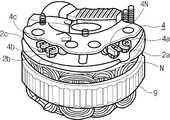
상기 전기자코일(2)은 도 3에 나타낸 바와같이 원통형상의 전기자철심(고정자코어)(9)의 원주상에 형성된 복수의 슬롯(10)에 감아 장착되고, 그 코일의 U상, V상, W상의 출력단(2a, 2b, 2c) 및 중성점 출력단(N)은 전파정류기(4)의 애노드측 단자(4a, 4b, 4c 및 4N)에 각각 접속되어 있다. 여기서 상기 전기자코일의 도출코일은 통상 각 상 2개세트로 구성되어 직접 상기 애노드측 단자(4a, 4b, 4c)에 접속되나, 중성점의 도출코일(2N)은 2개세트의 것을 U상, V상, W상으로 조합시켜 1개의 중성점 출력단(N)을 포함하여 집속단자(12)에 의하여 결속되어 있다.The
다음에 도 1로 되돌아가서 중성점의 6개의 도출코일(2N)과 중성점 출력단(N)과 집속단자(12)의 관계를 설명하면, 도출코일(2N)은 2단적으로 배치되어 하단에 3열, 상단에 중성점 출력단(N)을 포함하여 4열 배치되고, 상하의 코일은 서로 겹치지 않도록 갈짓자모양으로 교대로 배열되어 있다. 그리고 이들 배열된 도출코일은 구리계 재료로 이루어지는 집속단자(12)로 묶여지고, 각각이 납재(31)를 거쳐 그 집속단자(12)와 전기적으로 또한 기계적으로 결합되어 있어 선간 끼리도 서로 가압접촉하고 있다.Next, referring back to FIG. 1, the relationship between the six
다음에 상기 구성의 집속단자와 도출코일의 결합방법에 관하여 후기한다.Next, the coupling method of the converging terminal and the derivation coil of the above configuration will be described later.
전기자코일(2)의 연장선인 중성점 도출코일(2N)은 일반적으로 에나멜피복도선인 AIW선이 이용되고, 집속단자(12)에는 AIW선의 통전가열의 접합에 좋은 결과를 초래하는 구리합금단자가 이용된다.The neutral
도 5 ~ 도 10은 집속단자와 도출코일의 결합법이다. 전기자철심(9)의 슬롯(10)에 감아 장착된 채의 전기자코일(2)의 도출코일은 통상 U, V, W상 출력단(2a, 2b, 2c)과 중성점 도출코일(2N)과도 축방향으로 연장되어 있기 때문에 본 실시예에서는 양자의 혼재를 피하고, 작업성을 향상시키기 위해 중성점측 도출코일을 도 5(a)에 나타낸 바와같이 전기자철심(9)의 축방향에 대하여 대략 수직방향으로 미리 구부려 놓았다.5 to 10 are a combination method of the focusing terminal and the derivation coil. The coil of the
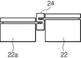
이와 같이 권선된 중성점측 도출코일(2N)은 각각의 지지핀(20, 20a)을 거쳐 자유롭게 회동할 수 있게 정형블레이드(21, 21a)를 배치한 좌우 한쌍의 묶음블록(22, 22a)의 코일가이드공간(23, 23a)에 배치된다. 그리고 상기 정형블레이드(21, 21a)를 전기자철심의 외주방향으로 밀어넣음으로써 각각의 코일은 상기 전기자철심의 둘레방향을 따라 변형되고, 묶음블록(22, 22a)사이에 배치된 S자 끼움목(24)에 밀어넣어진다. 여기서 상기 정형블레이드(21, 21a)의 압압면은 원호상으로 형성되어 있고 또한 코일가이드공간(23, 23a)은 축방향으로 단차로 배치되어 S자 끼움목(24)의 홈에 대향하고 있다.The coils of the neutral
따라서 정형블레이드(21, 21a)에 의하여 둘레방향으로 밀어넣어진 중성점 도출코일(2N)은 도 6의 (a), (b)에서 알 수 있는 바와 같이 근원부는 정형블레이드의 원호면(21b)을 따라 정형되고, 선단방향은 평행면(21c)에 의하여 직각적으로 굴곡되어 S자 끼움목의 홈에 밀어넣어지고, 단차를 두고 정렬된다.Therefore, the neutral
다음에 도 7의 행정에서는 S자 끼움목(24)을 직각으로 일으켜 다른 전기자코일(2)의 U, V, W상의 출력단(2a, 2b, 2c)과 동일한 방향으로 다시 모으고, 조립의 자동화에 대비한다. 이 상태에서 S자 끼움목(24)을 제거하면, 중성점 도출코일(2N)은 제 각각이 되기 때문에 다음행정 도 7(b)에서는 S자 끼움목(24)을 끼워넣은 채 양측에서 정형톱니(25b)를 가지는 한쌍의 척(25, 25a)로 중성점도출코일(2N)을 정렬하여 밀착시킨다.Next, in the stroke of Fig. 7, the S-
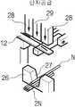
이와 같이 하여 정렬된 도출코일은 다음행정, 도 8에서 중성점 출력단(N)을 끼워 집속단자(12)에 의해 코킹고정된다. 이 행정은 상기 중성점 도출코일(2N)을 중성점 출력단(N)과 함께 사다리꼴 홈(27)을 가지는 받이형(26)의 상기 홈바닥에 배치한 후 집속단자로 되는 결속밴드(27)를 공급하는 행정, 도 8(a)와 상기 공급된 집속단자(12)를 커터(28)로 규정치수로 절단하고, 상기 커터(28)와 누름형(29)과 받이형(30)에 의해 집속단자(12)를 U자 형상으로 성형하는 행정, 도 8(b)와 상기 집속단자(12)를 커터(28)와 누름형(29)으로 주위를 구속하면서 누름형(29)을 하강시켜 상기 받이형(26)의 사다리꼴 홈에 밀어넣는 행정, 도 8(c)와, 또한 누름형을 하강시켜 중성점 도출코일(2N)과 중성점 출력단자(N)를 집속단자(12)로 싸넣어 코킹고정하는 행정, 도 8(d)로 이루어진다.The derivation coils arranged in this manner are caulked by the focusing
물론 상기 행정의 최종공정은 7개의 코일을 2단적으로 하고, 서로 어긋난 배치는 바뀌지 않도록 가공되고, 도 9와 같이 구성된다. 이 시점에서는 에나멜피복(30) 및 납재(31)가 개재되어 있기 때문에 그만큼 고려하여 갭(g)이 생기는 치수로 하고 있다.Of course, the final process of the above step is performed in two stages of the seven coils, and processed so that the arrangements shifted from each other are not changed and are configured as shown in FIG. At this point of time, since the enamel coating 30 and the
그후 최종공정, 도 10으로 이행하여 가공면을 평면(32a)으로 한 전극(32)과, 가압면을 집속단자의 최종형상인 오목면(33a)으로 한 전극(33)에 의해 상기 집속단자를 가압하여 통전을 행한다. 이 때의 가압, 통전조건은 단자 내주면이 코일피막의 연화온도 이상이 되도록 설정한다. 이와 관련하여 차량용 교류발전기고정자에 이용하는 고정자코일은 내열전선피막(AIW)선의 탄화온도는 약 650℃이다. 이로써 통전가압행정시에 상기 단자와 접촉하고 있는 도출코일(N 및 2N)은 외주의 일측면부분의 피막이 탄화하고, 전극의 가압력에 의하여 탄화한 에나멜피막(30)은 집속단자(12)의 외측으로 배출되고, 코일은 진선이 노출되게 된다. 그후 도출코일측면과 접촉하고 있는 단자 내주면이 야금적으로 결합된다. 또 단자내의 코일간 끼리는 성형된 단자의 구속력에 의하여 압접 접합된다. 이와 같이 중성점 도출코일(2N) 및 중성점단(N)의 접속은 각 코일 외주의 일측면과 집속단자(12)의 내주면과의 야금적접합과 코일간의 압접의 양자에 의하여 확실하게 행하여진다.Thereafter, the final process proceeds to Fig. 10, whereby the focusing terminal is formed by the
이 방식에 의하면, 접합하기 전의 코일에나멜부의 박리가 생략되기 때문에 확실하게 작업공정수 및 작업인원을 저감할 수 있다. 또 차량용 교류발전기고정자의 중성점부의 온도는 실차(빈차의 반대)주행시에는 약 200℃부근까지 상승하기 때문에 결합이 납땜의 경우 땜납 자신의 내열성이 낮아 신뢰성에 어려움이 있었으나, 본 방식의 경우, 결합을 야금적으로 행할 수 있기 때문에 내열성이 현저하게 향상하고, 내진성과 함께 신뢰성이 향상한다.According to this system, since the peeling of the enamel portion before the joining is omitted, the number of work steps and the number of people can be reliably reduced. In addition, since the temperature of the neutral point of the AC generator stator for a vehicle rises to around 200 ° C when driving a vehicle (opposite to the empty vehicle), the coupling has difficulty in reliability because of low heat resistance of the solder itself when soldering. Since it can be performed metallurgically, heat resistance remarkably improves and reliability improves with earthquake resistance.
또 접합부의 신뢰성을 향상시키기 위해 집속단자 내주면에 인동납을 붙여 이 면이 코일접촉측이 되도록 하면, 접합부는 더욱 신뢰성을 향상할 수 있다.In order to improve the reliability of the joint, if the solder lead is attached to the inner circumferential surface of the focusing terminal so that the surface becomes the coil contact side, the joint can be further improved.
또한 상기 실시예에서는 에나멜피복선의 결합을 중심으로 설명하였으나, 집속단자 내주면과 코일에나멜부 사이에 납재를 개재하여 접속하면 더욱 양호하다. 또 본 발명은 특히 3개 이상의 코일을 묶었을 때의 결합강도를 올리는데 유효하며 집속단자의 형상 및 이음매의 형상은 상관없다.In addition, in the above embodiment, the coupling between the enamel coated wires has been described, but it is better to connect the solder terminal between the inner peripheral surface of the focusing terminal and the coil enamel. In addition, the present invention is particularly effective in increasing the bonding strength when three or more coils are bundled together, and the shape of the focusing terminal and the shape of the joint are irrelevant.
또 본 발명은 이들 실시예에 그치는 것이 아니라 3개 이상의 리드선을 묶어 고정하는 것에 유효하고 높은 결합력이 얻어진다.In addition, the present invention is not limited to these examples, and is effective for binding and fixing three or more lead wires, thereby obtaining a high bonding force.
도출코일세트의 각각의 도출코일을 코일 주위의 일부가 적어도 집속단자에 접촉하여 접합하도록 하였기 때문에 결합력이 안정되어 신뢰성이 높은 집속단자와 도출코일의 결합구조와 그것을 이용한 소형 회전전기 및 차량용 교류발전기가 얻어진다.Since each of the guide coils of the lead-out coil set is joined to at least a part of the coil in contact with the focusing terminal, the coupling force is stable, and the coupling structure of the reliable focusing terminal and the leading coil and the small rotating electric and automotive alternator using the same Obtained.
도 1은 본 발명의 집속단자와 도출코일의 결합구조를 나타낸 종단면도,1 is a longitudinal sectional view showing a coupling structure of a focusing terminal and a derivation coil of the present invention;
도 2는 본 발명을 이용한 차량용 교류발전기의 회로구성도,2 is a circuit diagram of a vehicle alternator using the present invention;
도 3은 상기 차량용 교류발전기의 종단면도,3 is a longitudinal sectional view of the vehicle alternator;
도 4는 상기 차량용 교류발전기의 전기자철심과 정류기의 사시도,4 is a perspective view of an electric magnet core and a rectifier of the automotive alternator;
도 5는 상기 본 발명의 실시예에 있어서의 도출코일정형장치의 평면도 및 측면도,5 is a plan view and a side view of the derivation coil shaping apparatus according to the embodiment of the present invention;
도 6은 상기 정형장치의 정형상태의 평면도 및 측면도,6 is a plan view and a side view of a shaping state of the shaping device;
도 7은 상기 정형장치의 다음행정에 있어서의 도출코일정형정렬장치의 사시도,Fig. 7 is a perspective view of the derivation coil shaping device in the next stroke of the shaping device;
도 8은 상기 정형장치의 집속단자의 공급, 절단, 정형, 코킹행정을 나타낸 사시도,Figure 8 is a perspective view showing the supply, cutting, shaping, caulking stroke of the focusing terminal of the shaping device;
도 9는 상기 행정에서 얻어진 집속단자의 코킹완료단면도,9 is a caulking completion cross-sectional view of the focusing terminal obtained in the above stroke;
도 10은 상기 집속단자 통전가열행정 사시도이다.10 is a perspective view of the energizing heating administration of the focusing terminal.
(도면의 주요부분에 대한 부호의 설명)(Explanation of symbols for main parts of drawing)
2 : 전기자코일2a, 2b, 2c : 도출코일의 출력단2:
4 : 전파정류기4a, 4b, 4c : 애노드측 단자4: Full-
2N : 중성점 도출코일N : 중성점 출력단2N: Neutral point derivation coil N: Neutral point output
12 : 집속단자12: focusing terminal
Claims (16)
Translated fromKoreanApplications Claiming Priority (2)
| Application Number | Priority Date | Filing Date | Title |
|---|---|---|---|
| JP8153703AJPH104646A (en) | 1996-06-14 | 1996-06-14 | Coupling structure of focusing terminal and derived coil, and small rotating electric machine and vehicle alternator using the same |
| JP8-153703 | 1996-06-14 |
Publications (2)
| Publication Number | Publication Date |
|---|---|
| KR980006728A KR980006728A (en) | 1998-03-30 |
| KR100516853B1true KR100516853B1 (en) | 2005-12-16 |
Family
ID=15568271
Family Applications (1)
| Application Number | Title | Priority Date | Filing Date |
|---|---|---|---|
| KR1019970024432AExpired - Fee RelatedKR100516853B1 (en) | 1996-06-14 | 1997-06-13 | Combination structure of focusing terminal and escape coil and small rotating electric motor and vehicle alternator using it |
Country Status (3)
| Country | Link |
|---|---|
| US (1) | US5914546A (en) |
| JP (1) | JPH104646A (en) |
| KR (1) | KR100516853B1 (en) |
Families Citing this family (16)
| Publication number | Priority date | Publication date | Assignee | Title |
|---|---|---|---|---|
| US4702769A (en)* | 1982-05-21 | 1987-10-27 | Toshiba Tungaloy Co., Ltd. | Sintered alloy for decoration |
| JP3374776B2 (en)* | 1999-02-05 | 2003-02-10 | 株式会社デンソー | AC generator for vehicles |
| JP2000232745A (en)* | 1999-02-10 | 2000-08-22 | Toshiba Kyaria Kk | Motor for compressor |
| JP3578142B2 (en)* | 2002-01-15 | 2004-10-20 | 株式会社日立製作所 | Connection structure, connection method thereof, rotating electric machine and AC generator using the same |
| JP4608775B2 (en)* | 2000-12-20 | 2011-01-12 | 日産自動車株式会社 | Rotating electric machine |
| JP3944357B2 (en)* | 2001-02-08 | 2007-07-11 | 三菱電機株式会社 | AC generator for vehicles |
| JP2003111334A (en)* | 2001-09-28 | 2003-04-11 | Denso Corp | Vehicle alternator |
| JP2003209944A (en) | 2002-01-10 | 2003-07-25 | Mitsubishi Electric Corp | Rotating electric machine and method of manufacturing the same |
| AU2003266579A1 (en)* | 2002-09-24 | 2004-04-19 | Sawafuji Electric Co., Ltd. | Stator for outer rotor multipole generator and method of assembling the stator |
| JP4546112B2 (en) | 2004-03-02 | 2010-09-15 | 日立オートモティブシステムズ株式会社 | Rotating electric machine |
| KR100725738B1 (en) | 2005-09-30 | 2007-06-08 | 삼성전자주식회사 | motor |
| US8134268B2 (en)* | 2009-01-09 | 2012-03-13 | Honeywell International, Inc. | Wound field electrical machine flat braided wire main rotor crossover assembly |
| US8878406B2 (en)* | 2011-12-06 | 2014-11-04 | Remy Technologies, L.L.C. | Stator including conductors provided with a composite sleeve |
| JP5505530B1 (en)* | 2013-02-15 | 2014-05-28 | 三菱電機株式会社 | Rotating electric machine |
| CN110957865A (en)* | 2019-12-03 | 2020-04-03 | 大冶东艾电机有限公司 | An operation method for 100% conduction rate of motor lead joint crimping |
| CN216903370U (en)* | 2022-03-24 | 2022-07-05 | 瑞智精密股份有限公司 | Terminal connection structure of compressor motor enameled wire |
Citations (2)
| Publication number | Priority date | Publication date | Assignee | Title |
|---|---|---|---|---|
| JPH01283047A (en)* | 1988-05-02 | 1989-11-14 | Hitachi Ltd | Neutral-connecting method for ac generator |
| JPH05300688A (en)* | 1992-04-21 | 1993-11-12 | Fujitsu General Ltd | Connection of conductor |
Family Cites Families (7)
| Publication number | Priority date | Publication date | Assignee | Title |
|---|---|---|---|---|
| US3805221A (en)* | 1972-10-25 | 1974-04-16 | Thomas & Betts Corp | Inspectable-corrosion resistant electrical connector |
| US4354133A (en)* | 1980-08-29 | 1982-10-12 | The United States Of America As Represented By The Secretary Of The Army | Hermetically sealed container |
| US4602424A (en)* | 1984-06-04 | 1986-07-29 | General Electric Company | Methods of insulating lead connections for dynamoelectric machine windings |
| JPH0714552B2 (en)* | 1987-10-09 | 1995-02-22 | 株式会社日立製作所 | Insulation film Wire and terminal joining method |
| JP2644860B2 (en)* | 1988-11-18 | 1997-08-25 | 株式会社日立製作所 | Crimp terminal |
| DE4031440A1 (en)* | 1990-10-04 | 1992-04-09 | Mulfingen Elektrobau Ebm | ELECTRIC MOTOR WITH CONNECTOR |
| JP2965825B2 (en)* | 1993-07-22 | 1999-10-18 | 出光石油化学株式会社 | Multilayer structure and easy-open container |
- 1996
- 1996-06-14JPJP8153703Apatent/JPH104646A/enactivePending
- 1997
- 1997-06-13KRKR1019970024432Apatent/KR100516853B1/ennot_activeExpired - Fee Related
- 1997-06-16USUS08/876,531patent/US5914546A/ennot_activeExpired - Lifetime
Patent Citations (2)
| Publication number | Priority date | Publication date | Assignee | Title |
|---|---|---|---|---|
| JPH01283047A (en)* | 1988-05-02 | 1989-11-14 | Hitachi Ltd | Neutral-connecting method for ac generator |
| JPH05300688A (en)* | 1992-04-21 | 1993-11-12 | Fujitsu General Ltd | Connection of conductor |
Also Published As
| Publication number | Publication date |
|---|---|
| JPH104646A (en) | 1998-01-06 |
| KR980006728A (en) | 1998-03-30 |
| US5914546A (en) | 1999-06-22 |
Similar Documents
| Publication | Publication Date | Title |
|---|---|---|
| KR100516853B1 (en) | Combination structure of focusing terminal and escape coil and small rotating electric motor and vehicle alternator using it | |
| JP3578142B2 (en) | Connection structure, connection method thereof, rotating electric machine and AC generator using the same | |
| US6624544B2 (en) | Neutral-point joint portion of stator winding for an alternator | |
| US5508571A (en) | Neutral connection for wire wound stator | |
| JP3775317B2 (en) | Manufacturing method of winding of rotating electric machine | |
| JP3964122B2 (en) | AC generator for vehicle and method for forming connection locking portion of conductor wire applied to stator winding thereof | |
| KR100541334B1 (en) | Rotary electric machine | |
| JP3303854B2 (en) | Joint wire and joining method | |
| JP3431948B2 (en) | Method for Preparing Half-Coil of Solid Phase Connector and Stator Phase Winding | |
| CN103490545A (en) | Electric power collection and distribution ring, electric motor and method of manufacturing electric motor | |
| JP2001231209A (en) | AC generator for vehicles | |
| JP2000069705A (en) | Rotating electric machine stator | |
| JP4066834B2 (en) | Manufacturing method of winding of rotating electric machine | |
| JP6536933B2 (en) | Manufacturing method of wire with terminal | |
| CN108370189A (en) | The manufacturing method of stator, electric rotating machine and stator | |
| JP3740433B2 (en) | Coupling structure of focusing terminal and lead-out coil and small rotating electric machine and vehicular AC generator using the same | |
| EP0632934B1 (en) | Method and apparatus for making an armature | |
| EP0201129B2 (en) | Method of manufacturing an electrical machine part | |
| JP3724375B2 (en) | Vehicle alternator | |
| JP3698423B2 (en) | Coil connection wire for stator and stator | |
| KR102791701B1 (en) | Stator winding connection structure for BLDC motor | |
| US8978238B2 (en) | Apparatus and method for efficient stator windings termination | |
| JP2003164093A (en) | Method for connecting motor leads, method for manufacturing three-phase motor using the same, and connection structure for motor leads | |
| JP2005093146A (en) | CONNECTION STRUCTURE FOR CONNECTING CONDUCTORS AND METHOD AND CONNECTION METHOD, AND ROTARY ELECTRIC AND AC AC GENERATOR USING THE SAME | |
| JP2001078404A (en) | Winding forming method |
Legal Events
| Date | Code | Title | Description |
|---|---|---|---|
| PA0109 | Patent application | St.27 status event code:A-0-1-A10-A12-nap-PA0109 | |
| R17-X000 | Change to representative recorded | St.27 status event code:A-3-3-R10-R17-oth-X000 | |
| PG1501 | Laying open of application | St.27 status event code:A-1-1-Q10-Q12-nap-PG1501 | |
| R18-X000 | Changes to party contact information recorded | St.27 status event code:A-3-3-R10-R18-oth-X000 | |
| PN2301 | Change of applicant | St.27 status event code:A-3-3-R10-R13-asn-PN2301 St.27 status event code:A-3-3-R10-R11-asn-PN2301 | |
| A201 | Request for examination | ||
| AMND | Amendment | ||
| P11-X000 | Amendment of application requested | St.27 status event code:A-2-2-P10-P11-nap-X000 | |
| P13-X000 | Application amended | St.27 status event code:A-2-2-P10-P13-nap-X000 | |
| PA0201 | Request for examination | St.27 status event code:A-1-2-D10-D11-exm-PA0201 | |
| E902 | Notification of reason for refusal | ||
| PE0902 | Notice of grounds for rejection | St.27 status event code:A-1-2-D10-D21-exm-PE0902 | |
| T11-X000 | Administrative time limit extension requested | St.27 status event code:U-3-3-T10-T11-oth-X000 | |
| T11-X000 | Administrative time limit extension requested | St.27 status event code:U-3-3-T10-T11-oth-X000 | |
| T11-X000 | Administrative time limit extension requested | St.27 status event code:U-3-3-T10-T11-oth-X000 | |
| R18-X000 | Changes to party contact information recorded | St.27 status event code:A-3-3-R10-R18-oth-X000 | |
| T11-X000 | Administrative time limit extension requested | St.27 status event code:U-3-3-T10-T11-oth-X000 | |
| T11-X000 | Administrative time limit extension requested | St.27 status event code:U-3-3-T10-T11-oth-X000 | |
| AMND | Amendment | ||
| P11-X000 | Amendment of application requested | St.27 status event code:A-2-2-P10-P11-nap-X000 | |
| P13-X000 | Application amended | St.27 status event code:A-2-2-P10-P13-nap-X000 | |
| E601 | Decision to refuse application | ||
| PE0601 | Decision on rejection of patent | St.27 status event code:N-2-6-B10-B15-exm-PE0601 | |
| T11-X000 | Administrative time limit extension requested | St.27 status event code:U-3-3-T10-T11-oth-X000 | |
| J201 | Request for trial against refusal decision | ||
| PJ0201 | Trial against decision of rejection | St.27 status event code:A-3-3-V10-V11-apl-PJ0201 | |
| AMND | Amendment | ||
| P11-X000 | Amendment of application requested | St.27 status event code:A-2-2-P10-P11-nap-X000 | |
| P13-X000 | Application amended | St.27 status event code:A-2-2-P10-P13-nap-X000 | |
| PB0901 | Examination by re-examination before a trial | St.27 status event code:A-6-3-E10-E12-rex-PB0901 | |
| B701 | Decision to grant | ||
| PB0701 | Decision of registration after re-examination before a trial | St.27 status event code:A-3-4-F10-F13-rex-PB0701 | |
| GRNT | Written decision to grant | ||
| PR0701 | Registration of establishment | St.27 status event code:A-2-4-F10-F11-exm-PR0701 | |
| PR1002 | Payment of registration fee | St.27 status event code:A-2-2-U10-U11-oth-PR1002 Fee payment year number:1 | |
| PG1601 | Publication of registration | St.27 status event code:A-4-4-Q10-Q13-nap-PG1601 | |
| FPAY | Annual fee payment | Payment date:20080902 Year of fee payment:4 | |
| PR1001 | Payment of annual fee | St.27 status event code:A-4-4-U10-U11-oth-PR1001 Fee payment year number:4 | |
| LAPS | Lapse due to unpaid annual fee | ||
| PC1903 | Unpaid annual fee | St.27 status event code:A-4-4-U10-U13-oth-PC1903 Not in force date:20090916 Payment event data comment text:Termination Category : DEFAULT_OF_REGISTRATION_FEE | |
| PC1903 | Unpaid annual fee | St.27 status event code:N-4-6-H10-H13-oth-PC1903 Ip right cessation event data comment text:Termination Category : DEFAULT_OF_REGISTRATION_FEE Not in force date:20090916 | |
| P22-X000 | Classification modified | St.27 status event code:A-4-4-P10-P22-nap-X000 |