KR100486803B1 - Selfluminous display device - Google Patents
Selfluminous display deviceDownload PDFInfo
- Publication number
- KR100486803B1 KR100486803B1KR1019970025142AKR19970025142AKR100486803B1KR 100486803 B1KR100486803 B1KR 100486803B1KR 1019970025142 AKR1019970025142 AKR 1019970025142AKR 19970025142 AKR19970025142 AKR 19970025142AKR 100486803 B1KR100486803 B1KR 100486803B1
- Authority
- KR
- South Korea
- Prior art keywords
- light emitting
- layer
- semiconductor
- sources
- display device
- Prior art date
- Legal status (The legal status is an assumption and is not a legal conclusion. Google has not performed a legal analysis and makes no representation as to the accuracy of the status listed.)
- Expired - Fee Related
Links
Images


Classifications
- G—PHYSICS
- G09—EDUCATION; CRYPTOGRAPHY; DISPLAY; ADVERTISING; SEALS
- G09G—ARRANGEMENTS OR CIRCUITS FOR CONTROL OF INDICATING DEVICES USING STATIC MEANS TO PRESENT VARIABLE INFORMATION
- G09G3/00—Control arrangements or circuits, of interest only in connection with visual indicators other than cathode-ray tubes
- G09G3/20—Control arrangements or circuits, of interest only in connection with visual indicators other than cathode-ray tubes for presentation of an assembly of a number of characters, e.g. a page, by composing the assembly by combination of individual elements arranged in a matrix no fixed position being assigned to or needed to be assigned to the individual characters or partial characters
- G09G3/34—Control arrangements or circuits, of interest only in connection with visual indicators other than cathode-ray tubes for presentation of an assembly of a number of characters, e.g. a page, by composing the assembly by combination of individual elements arranged in a matrix no fixed position being assigned to or needed to be assigned to the individual characters or partial characters by control of light from an independent source
- G09G3/3406—Control of illumination source
- G09G3/3413—Details of control of colour illumination sources
- H—ELECTRICITY
- H01—ELECTRIC ELEMENTS
- H01S—DEVICES USING THE PROCESS OF LIGHT AMPLIFICATION BY STIMULATED EMISSION OF RADIATION [LASER] TO AMPLIFY OR GENERATE LIGHT; DEVICES USING STIMULATED EMISSION OF ELECTROMAGNETIC RADIATION IN WAVE RANGES OTHER THAN OPTICAL
- H01S5/00—Semiconductor lasers
- H01S5/40—Arrangement of two or more semiconductor lasers, not provided for in groups H01S5/02 - H01S5/30
- H01S5/42—Arrays of surface emitting lasers
- H01S5/423—Arrays of surface emitting lasers having a vertical cavity
- B—PERFORMING OPERATIONS; TRANSPORTING
- B82—NANOTECHNOLOGY
- B82Y—SPECIFIC USES OR APPLICATIONS OF NANOSTRUCTURES; MEASUREMENT OR ANALYSIS OF NANOSTRUCTURES; MANUFACTURE OR TREATMENT OF NANOSTRUCTURES
- B82Y20/00—Nanooptics, e.g. quantum optics or photonic crystals
- G—PHYSICS
- G09—EDUCATION; CRYPTOGRAPHY; DISPLAY; ADVERTISING; SEALS
- G09G—ARRANGEMENTS OR CIRCUITS FOR CONTROL OF INDICATING DEVICES USING STATIC MEANS TO PRESENT VARIABLE INFORMATION
- G09G3/00—Control arrangements or circuits, of interest only in connection with visual indicators other than cathode-ray tubes
- G09G3/20—Control arrangements or circuits, of interest only in connection with visual indicators other than cathode-ray tubes for presentation of an assembly of a number of characters, e.g. a page, by composing the assembly by combination of individual elements arranged in a matrix no fixed position being assigned to or needed to be assigned to the individual characters or partial characters
- G09G3/34—Control arrangements or circuits, of interest only in connection with visual indicators other than cathode-ray tubes for presentation of an assembly of a number of characters, e.g. a page, by composing the assembly by combination of individual elements arranged in a matrix no fixed position being assigned to or needed to be assigned to the individual characters or partial characters by control of light from an independent source
- G09G3/3406—Control of illumination source
- G09G3/342—Control of illumination source using several illumination sources separately controlled corresponding to different display panel areas, e.g. along one dimension such as lines
- G09G3/3426—Control of illumination source using several illumination sources separately controlled corresponding to different display panel areas, e.g. along one dimension such as lines the different display panel areas being distributed in two dimensions, e.g. matrix
- H—ELECTRICITY
- H01—ELECTRIC ELEMENTS
- H01S—DEVICES USING THE PROCESS OF LIGHT AMPLIFICATION BY STIMULATED EMISSION OF RADIATION [LASER] TO AMPLIFY OR GENERATE LIGHT; DEVICES USING STIMULATED EMISSION OF ELECTROMAGNETIC RADIATION IN WAVE RANGES OTHER THAN OPTICAL
- H01S5/00—Semiconductor lasers
- H01S5/40—Arrangement of two or more semiconductor lasers, not provided for in groups H01S5/02 - H01S5/30
- H01S5/4025—Array arrangements, e.g. constituted by discrete laser diodes or laser bar
- H01S5/4087—Array arrangements, e.g. constituted by discrete laser diodes or laser bar emitting more than one wavelength
- H01S5/4093—Red, green and blue [RGB] generated directly by laser action or by a combination of laser action with nonlinear frequency conversion
- H—ELECTRICITY
- H10—SEMICONDUCTOR DEVICES; ELECTRIC SOLID-STATE DEVICES NOT OTHERWISE PROVIDED FOR
- H10H—INORGANIC LIGHT-EMITTING SEMICONDUCTOR DEVICES HAVING POTENTIAL BARRIERS
- H10H29/00—Integrated devices, or assemblies of multiple devices, comprising at least one light-emitting semiconductor element covered by group H10H20/00
- H10H29/10—Integrated devices comprising at least one light-emitting semiconductor component covered by group H10H20/00
- H10H29/14—Integrated devices comprising at least one light-emitting semiconductor component covered by group H10H20/00 comprising multiple light-emitting semiconductor components
- H10H29/142—Two-dimensional arrangements, e.g. asymmetric LED layout
- H—ELECTRICITY
- H01—ELECTRIC ELEMENTS
- H01S—DEVICES USING THE PROCESS OF LIGHT AMPLIFICATION BY STIMULATED EMISSION OF RADIATION [LASER] TO AMPLIFY OR GENERATE LIGHT; DEVICES USING STIMULATED EMISSION OF ELECTROMAGNETIC RADIATION IN WAVE RANGES OTHER THAN OPTICAL
- H01S5/00—Semiconductor lasers
- H01S5/30—Structure or shape of the active region; Materials used for the active region
- H01S5/32—Structure or shape of the active region; Materials used for the active region comprising PN junctions, e.g. hetero- or double- heterostructures
- H01S5/327—Structure or shape of the active region; Materials used for the active region comprising PN junctions, e.g. hetero- or double- heterostructures in AIIBVI compounds, e.g. ZnCdSe-laser
- H—ELECTRICITY
- H01—ELECTRIC ELEMENTS
- H01S—DEVICES USING THE PROCESS OF LIGHT AMPLIFICATION BY STIMULATED EMISSION OF RADIATION [LASER] TO AMPLIFY OR GENERATE LIGHT; DEVICES USING STIMULATED EMISSION OF ELECTROMAGNETIC RADIATION IN WAVE RANGES OTHER THAN OPTICAL
- H01S5/00—Semiconductor lasers
- H01S5/30—Structure or shape of the active region; Materials used for the active region
- H01S5/34—Structure or shape of the active region; Materials used for the active region comprising quantum well or superlattice structures, e.g. single quantum well [SQW] lasers, multiple quantum well [MQW] lasers or graded index separate confinement heterostructure [GRINSCH] lasers
- H01S5/343—Structure or shape of the active region; Materials used for the active region comprising quantum well or superlattice structures, e.g. single quantum well [SQW] lasers, multiple quantum well [MQW] lasers or graded index separate confinement heterostructure [GRINSCH] lasers in AIIIBV compounds, e.g. AlGaAs-laser, InP-based laser
- H01S5/34333—Structure or shape of the active region; Materials used for the active region comprising quantum well or superlattice structures, e.g. single quantum well [SQW] lasers, multiple quantum well [MQW] lasers or graded index separate confinement heterostructure [GRINSCH] lasers in AIIIBV compounds, e.g. AlGaAs-laser, InP-based laser with a well layer based on Ga(In)N or Ga(In)P, e.g. blue laser
- H—ELECTRICITY
- H01—ELECTRIC ELEMENTS
- H01S—DEVICES USING THE PROCESS OF LIGHT AMPLIFICATION BY STIMULATED EMISSION OF RADIATION [LASER] TO AMPLIFY OR GENERATE LIGHT; DEVICES USING STIMULATED EMISSION OF ELECTROMAGNETIC RADIATION IN WAVE RANGES OTHER THAN OPTICAL
- H01S5/00—Semiconductor lasers
- H01S5/40—Arrangement of two or more semiconductor lasers, not provided for in groups H01S5/02 - H01S5/30
- H01S5/4025—Array arrangements, e.g. constituted by discrete laser diodes or laser bar
- H01S5/4087—Array arrangements, e.g. constituted by discrete laser diodes or laser bar emitting more than one wavelength
Landscapes
- Physics & Mathematics (AREA)
- Engineering & Computer Science (AREA)
- Optics & Photonics (AREA)
- General Physics & Mathematics (AREA)
- Nanotechnology (AREA)
- Chemical & Material Sciences (AREA)
- Condensed Matter Physics & Semiconductors (AREA)
- Electromagnetism (AREA)
- Crystallography & Structural Chemistry (AREA)
- Biophysics (AREA)
- Life Sciences & Earth Sciences (AREA)
- Computer Hardware Design (AREA)
- Theoretical Computer Science (AREA)
- Led Devices (AREA)
- Led Device Packages (AREA)
- Semiconductor Lasers (AREA)
Abstract
Translated fromKoreanDescription
Translated fromKorean본 발명은 일반적으로 표시 장치의 분야에 관한 것이며, 특히, 본 발명은 예를 들어 반도체 레이저 또는 발광 다이오드로 이루어진 복수의 발광원들을 구비한 자발광 표시 장치(selfluminous display device)에 관한 것이다.TECHNICAL FIELD The present invention generally relates to the field of display devices, and in particular, the present invention relates to a self-luminous display device having a plurality of light emitting sources consisting of, for example, a semiconductor laser or a light emitting diode.
종래의 표시 장치들에는, 거치형 브라운관 즉, CRT(Cathode Ray Tube) 장치와 휴대용 및 박형 장치 실현의 요건을 만족시키는 플랫 패널 디스플레이(FPD: flat panel display)가 있다. 플랫 패널 디스플레이의 예로는 액정 디스플레이(LCD: liquid crystal display)가 있다. 이 표시 장치들에서, LCD 자체는 발광하지 않지만 백라이트를 이용하여 정보를 표시한다. 그와 대조적으로, CRT는 스스로 발광하는 발광 물질을 포함하는 자발광 표시 장치이다.Conventional display devices include a stationary CRT (Cathode Ray Tube) device and a flat panel display (FPD) that satisfies the requirements of portable and thin device realization. An example of a flat panel display is a liquid crystal display (LCD). In these display devices, the LCD itself does not emit light but displays information using a backlight. In contrast, a CRT is a self-luminous display device including a light emitting material that emits self.
근래, 음성 분야에서는 노이즈가 제거된 디지털 음원들이 확립된지 오래지만, 표시 장치에서는 확립되지 않았으며, 노이즈가 없는 명료한 색 재생 즉, 디지털 재생에 대한 요구가 증대하고 있다. 그러나, 종래의 자발광 표시 장치에서는, 디지털 재생성을 좋게 하는 것이 어려웠다. 이하 이 점에 대해 설명하겠다.Recently, digital sound sources from which noise has been removed have been established in the speech field, but they have not been established in display devices, and there is an increasing demand for clear color reproduction without noise, that is, digital reproduction. However, in the conventional self-luminous display device, it is difficult to improve digital reproducibility. This point will be described below.
도 10은 NTSC(National Television System Committee) 방식에 기초하여 CRT에 의해 재생 가능한 영역을 도시하고 있다. 이 도면에서 분명히 알 수 있듯이, 발광 물질을 이용하는 CRT에서는 일점 쇄선으로 도시된 삼각형(CRT)의 내부밖에 재생할 수 없다. 삼각형(CRT)이 주로 중심 근처에 있는 이유는 발광 물질들의 스펙트럼이 폭이 넓고, 색 순도가 열악하고 백색에 근접하기 때문이다. 또한, 발광 물질들에는 약간 상이한 에너지들의 천이 순위(transition order level)가 많이 있으며 천이 에너지에 분포가 있기 때문에 폭이 넓다. 그러나, 시간에 따른 변화 등으로 인하여 이 천이 순위 분포가 변화하며 색 재생성이 열화한다. 또한, 이 넓은 스펙트럼 폭 때문에 색 순도가 열화하고 또한 재생 범위가 좁아진다고 하는 문제가 있다. 실선으로 도시된 삼각형(LED)은 후술할 본 발명의 재생 가능한 영역을 보여준다.FIG. 10 shows an area that can be reproduced by the CRT based on the NTSC (National Television System Committee) method. As can be clearly seen in this figure, in the CRT using the luminescent material, only the inside of the triangle (CRT) shown by a dashed-dotted line can be reproduced. The reason why the triangle (CRT) is mainly near the center is that the spectrum of the luminescent materials is broad, poor in color purity and close to white. In addition, there are many transition order levels of slightly different energies in luminescent materials and they are wide because they are distributed in the transition energy. However, due to changes over time, this transition rank distribution changes and color reproducibility deteriorates. In addition, there is a problem that the color purity deteriorates and the reproduction range is narrowed due to this wide spectral width. The triangle (LED) shown by the solid line shows the reproducible area of the present invention which will be described later.
도 11은 CRT를 위한 종래의 적색(R), 녹색(G), 청색(B) 발광원의 발광 파장(λ)과 발광 강도 사이의 관계를 도시하고 있으며, 이 경우, 이들 발광원이 이용되는 자발광 표시 장치의 표시 강도(FNTSC)는 다음 수학식으로 표현될 수 있다.Fig. 11 shows the relationship between the emission wavelength [lambda] and the emission intensity of conventional red (R), green (G) and blue (B) light emitting sources for CRT, in which case these light emitting sources are used. The display intensity FNTSC of the self-luminous display device can be expressed by the following equation.

여기서, B, G, R은 발광 강도이며, bi, gi, ri는 계수들이다.Where B, G, and R are luminescence intensities, and bi , gi , ri are coefficients.
이들 RGB 발광원의 발광 강도의 스펙트럼은 각 광원의 열화로 인해 실선으로 도시된 상태에서 파선으로 도시된 상태로 변화한다. 이 도면에서도 분명히 알 수 있듯이, 스펙트럼 형상들의 폭이 넓고 또한 그 변화가 균일하지 않기 때문에, 표시 강도(FNTSC)를 보정하는 것이 어렵고, 따라서 상술한 바와 같이 색 재생성이 열화한다고 하는 문제가 있었다.The spectrum of the emission intensity of these RGB light sources changes from the state shown by the solid line to the state shown by the broken line due to the deterioration of each light source. As can be clearly seen from this figure, since the width of the spectral shapes and the change are not uniform, it is difficult to correct the display intensity FNTSC , and thus there is a problem that color reproduction is deteriorated as described above.
또한 액정 디스플레이(LCD)가 이용되는 플랫 패널 디스플레이에서도, 색 필터의 전송 스펙트럼에는 유한 강도를 획득하기 위한 폭이 있으며, 따라서 상술한 CRT 경우에서와 같은 문제들이 존재한다. 특히, 도 10에서 일점 쇄선으로 도시된 삼각형(LCD)의 내부밖에 재생할 수 없고 재생성이 나쁘다고 하는 문제가 있었다. 반대로, 색 순도를 향상시키기 위하여 좁은 전송 스펙트럼 대역을 가진 필터가 이용되면, 투과광 강도가 현저히 저하한다고 하는 문제가 있었다.Also in a flat panel display in which a liquid crystal display (LCD) is used, the transmission spectrum of the color filter has a width for obtaining a finite intensity, and thus there are problems as in the above-described CRT case. In particular, there is a problem in that only the inside of the triangle (LCD) shown by a dashed-dotted line in FIG. 10 can be reproduced and the reproducibility is bad. On the contrary, when a filter having a narrow transmission spectrum band is used to improve color purity, there is a problem that the transmitted light intensity is significantly lowered.
본 발명은 이들 문제점들에 비추어 이루어진 것으로, 본 발명의 목적은 발광 강도가 유일한 파라미터가 되도록 하고, 보다 넓은 범위의 색 재생성을 가지며 또한 시간에 따른 변화가 없는 발광 강도를 얻는 것이 가능한 자발광 표시 장치를 제공하는 데 있다.SUMMARY OF THE INVENTION The present invention has been made in view of these problems, and an object of the present invention is to make the luminescence intensity be the only parameter, to have a wider range of color reproducibility, and to obtain the luminescence intensity without change over time, which can be obtained. To provide.
본 발명의 자발광 표시 장치는 제각기 상호 실질적으로 중복하지 않는 레벨의 스펙트럼을 가진 복수의 발광원들을 포함한다. 복수의 발광원들은, 구체적으로, 적색, 녹색, 청색 반도체 발광 장치들(LED, LD)은 제각기 반 대역폭(half band width)이 30nm 이하인 프리커서 델타 함수형 스펙트럼(precursor delta function shaped spectra)을 가진다. 또는, 제각기 포락 함수(envelope function)의 반 대역폭이 30nm 이하인 스펙트럼을 가진 적색, 녹색, 청색 반도체 레이저들(LD) 또는 발광 다이오드들(LED)이 이용된다. 더 구체적으로, 이득 도파형(gain guided type) 또는 굴절률 도파형(refractive index guided type) 반도체 레이저들 또는 발광 다이오드들이 이용된다. 이들 소자는 기판 상에 II-VI족 화합물 반도체 또는 III-V족 화합물 반도체로 이루어진 적어도 제1 도전형의 클래드 층, 활성층 및 제2 도전형의 클래드 층을 포함한다.The self-luminous display device of the present invention includes a plurality of light emitting sources each having a spectrum of levels that do not substantially overlap each other. Specifically, the plurality of light emitting sources have red, green, and blue semiconductor light emitting devices (LED, LD) each having a precursor delta function shaped spectra having a half band width of 30 nm or less. Alternatively, red, green, blue semiconductor lasers (LD) or light emitting diodes (LEDs) are used, each having a spectrum in which a half bandwidth of the envelope function is 30 nm or less. More specifically, gain guided type or refractive index guided type semiconductor lasers or light emitting diodes are used. These devices include a clad layer of at least a first conductivity type, an active layer, and a clad layer of a second conductivity type made of a II-VI compound semiconductor or a III-V compound semiconductor on a substrate.
본 발명의 자발광 표시 장치에서는, 복수의 광원들이 상호 실질적으로 중복하지 않는 스펙트럼을 갖기 때문에 즉, 극히 좁은 유한 폭의 발광원들이 이용되기 때문에, 스펙트럼의 형상 변화는 파장 공간으로는 억제되어 강도 변화만으로 간주될 수 있다. 따라서, 강도만을 파라미터로 가진 보정이 가능하게 된다.In the self-luminous display device of the present invention, since a plurality of light sources have a spectrum that does not substantially overlap each other, that is, because extremely narrow finite width light emitting sources are used, the shape change of the spectrum is suppressed in the wavelength space and thus the intensity change. Can only be considered. Therefore, correction with only intensity as a parameter is possible.
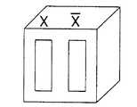
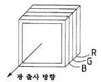
도 2는 본 발명의 제1 실시예에 따른 자발광 표시 장치의 발광부(100)의 아우트라인을 도시하고 있다. 이 자발광 표시 장치는 직시형 표시 장치 또는 투영형 표시 장치의 광원부일 수 있다. 발광부(100)는 다수의 서비 유닛(101)들로 구성되어 있다. 도 3은 하나의 서브 유닛(101)의 구체적인 구성예를 도시하고 있는데, 그것은 예를 들어 적색(R), 녹색(G), 청색(B)의 3원색의 발광원들(102a 내지 102c)을 포함한다. 도 4a 내지 도 4d는 서브 유닛(101)의 다른 예들을 도시하고 있다. 도 4a에 도시된 적색(R)과 다른 색(


도 5는 상술한 3개의 발광원들(102a 내지 102c) 각각의 스펙트럼을 도시하고 있다. 이들 발광원들(102a 내지 102c)의 스펙트럼은 반 대역폭이 좁고(30nm 이하), 상호 실질적으로 중첩하지 않는 정도로 되어 있으며, 다음 수학식의 프리커서 델타(δ) 함수로 간주될 수 있는 정도이다.5 shows the spectrum of each of the three light sources 102a to 102c described above. The spectra of these light emitting sources 102a to 102c are narrow in half bandwidth (below 30 nm), to the extent that they do not substantially overlap with each other, and can be regarded as a function of the precursor delta (δ) of the following equation.

이와 같은 프리커서 델타 함수형 스펙트럼을 가지는(즉, 유한 피크 치와 극히 좁은 유한 폭을 가지는) 발광원들(102a 내지 102c)에서는, 스펙트럼의 형상 변화는 파장 공간으로는 억제되며 강도 변화만으로 간주될 수 있다.In light emitting sources 102a to 102c having such a precursor delta functional spectrum (ie, having a finite peak and an extremely narrow finite width), the shape change of the spectrum is suppressed in the wavelength space and can only be regarded as the intensity change. have.
따라서, 본 실시예에 따른 자발광 표시 장치에서는, 3개의 발광원들(102a 내지 102c)에 의한 표시 강도(FDD)를 다음 수학식에서 볼 수 있듯이 상호 독립적인 유닛들의 합으로서 스펙트럼 표시하는 것이 가능하다. 즉, 스펙트럼 형상의 변화는 원칙적으로 극히 작으며, 모든 발광원들(102a 내지 102c)에서 각자의 강도를 변화시키는 것만으로 보정하는 것이 가능하며, 이 때문에 색 재생성이 현저히 향상되고 시간에 따른 변화가 없게 된다.Therefore, in the self-luminous display device according to the present embodiment, it is possible to display the display intensity FDD by the three light emitting sources 102a to 102c as a sum of mutually independent units as shown in the following equation. Do. That is, the change in the spectral shape is extremely small in principle, and it is possible to correct only by changing the intensity of each of the light emitting sources 102a to 102c, which leads to a marked improvement in color reproducibility and a change over time. There will be no.

여기서, B, G, R은 발광 강도이며, bi, gi, ri는 계수들이다.Where B, G, and R are luminescence intensities, and bi , gi , ri are coefficients.
따라서, 본 실시예에 따른 자발광 표시 장치에서는, 3개의 파라미터(3색 RGB의 강도)만으로 색도 다이어그램 상의 모든 점들을 우수한 점 정밀도(superior point precision)로 재생하는 것이 가능하며, 노이즈가 없는 명료한 표시 즉, 디지털 방식으로 색의 재생을 수행하는 것이 가능하다.Therefore, in the self-luminous display device according to the present embodiment, it is possible to reproduce all the points on the chromaticity diagram with superior point precision with only three parameters (intensity of three colors RGB), and the noise is clear and clear. It is possible to perform display of colors, i.e., digital reproduction.
또한, 본 실시예에 이용되는 3개 발광원들(102a 내지 102c)은 각각 프리커서 델타 함수형 스펙트럼을 가지기 때문에, 그것들은 도 11에 도시된 색도 좌표도의 바깥 둘레 상에 존재한다. 따라서, 이론상 허용되는 최대 색 재생 범위(도면의 삼각형(LED))를 획득하는 것이 가능하다. 이 예에서, 적색 발광원(102a)은 AlGaAs 화합물 반도체로 이루어진 발광 다이오드(LED)이다. 녹색 발광원(102b)은 ZnCdSe 화합물 반도체로 이루어진 것이며 청색 발광원(102c)은 GaInN 화합물 반도체로 이루어진 것으로 각각 도면에 도시되어 있다.In addition, since the three light emitting sources 102a to 102c used in this embodiment each have a precursor delta functional spectrum, they exist on the outer periphery of the chromaticity coordinate diagram shown in FIG. Thus, it is possible to obtain the theoretically acceptable maximum color reproduction range (triangle (LED) in the figure). In this example, the red light emitting source 102a is a light emitting diode (LED) made of AlGaAs compound semiconductor. The green
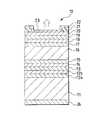
이하 적색, 녹색, 청색 발광원들(102a 내지 102c)의 구체적인 제조를 설명하겠다. 도 1은 도 3의 A-A' 선에 따른 단면 구조에 해당하며, 발광원들(102a, 102b, 102c)의 예로서 InP(인듐-인) 기판 상에 ZnCdMgSe 클래딩 층과 ZnCdMgSe 활성층을 포함하는 면발광형(surface emission type) 발광 다이오드(LED)의 구성을 도시하고 있다.Hereinafter, specific manufacturing of the red, green, and blue light emitting sources 102a to 102c will be described. FIG. 1 corresponds to a cross-sectional structure along the AA ′ line of FIG. 3, and includes a ZnCdMgSe cladding layer and a ZnCdMgSe active layer on an InP (indium-in) substrate as an example of light emitting
즉, 발광 다이오드(10)는 예를 들어 InP로 이루어진 n형 기판(11) 상에 예를 들어 n형 불순물로서 Cl(염소)이 도핑된 ZnCdSe 층(12a) 및 n형 불순물로서 Cl이 도핑된 Znx1Cdy1Mg1-x1-y1Se(0≤x1, y1≤1) 층(12b)으로 이루어진 약 700nm의 두께를 가진 n형 클래드 층(12), 예를 들어 n형 불순물로서 Cl이 도핑된 Znx2Cdy2Mg1-x2-y2Se(0≤x2, y2≤1)로 이루어진 약 100nm의 두께를 가진 n형 가이드 층(13), 예들 들어 단일 또는 다중 양자 우물 구조(single or multiple quantum well structure)로 된 Znx3Cdy3Mg1-x3-y3Se(0≤x3, y3≤1)로 이루어진 6 내지 12nm의 두께를 가진 활성층(14), 예를 들어 p형 불순물로서 N(질소)이 도핑된 Znx2Cdy2Mg1-x2-y2Se(0≤x2, y2≤1)로 이루어진 약 100nm의 두께를 가진 p형 가이드 층(15), 및 예를 들어 p형 불순물로서 N이 도핑된 Znx1Cdy1Mg1-x1-y1Se(0≤x1, y1≤1)로 이루어진 약 500nm의 두께를 가진 p형 클래드 층(16)을 순차적으로 성장시켜 제조된다. n형 클래드 층(12)과 p형 클래드 층(16)은 각각 활성층(14)보다 낮은 저항률을 가지며 광을 생성하는 기능은 물론 활성층(14)에 광 및 캐리어를 가두는 기능을 수행한다.That is, the
p형 클래드 층(16) 상에 부가적인 층들이 순차적으로 성장된다. 이들 부가적인 층에는, 예를 들어 p형 불순물로서 N이 도핑된 ZnCdMgSe로 이루어진 500nm의 두께를 가진 제1 반도체층(17)이 있다. 또한, ZnCdSe로 이루어진 약 100nm의 두께를 가진 제2 반도체층(18) 및 ZnSe와 CdSe가 교대로 적층된 초격자 반도체층(19), 및 N으로 도핑된 ZnxCd1-xSe(0≤x≤1)로 이루어진 콘택트 층(20)이 있다. 제1 반도체층(17), 제2 반도체층(18), 초격자 반도체층(19) 및 콘택트 층(20)은 p측 전극과의 양호한 옴 접촉을 제공한다. 콘택트 층(20) 상에는 폴리이미드 수지 등의 절연층(21)이 형성되며, 이 절연층(21) 내에 전류 통로 영역이 되는 개구부(21a)가 형성된다. 절연층(21)을 포함하는 콘택트 층(20) 상에 Pd(팔라듐), Pt(백금) 및 Au(금)의 적층막으로 이루어진 격자형 p측 전극(grill-like p-side electrode; 22)이 발광면(23)을 에워싸도록 형성된다. 또한, 기판(11)의 배면측에는 In(인듐) 등으로 이루어진 n측 전극(24)이 형성된다.Additional layers are grown sequentially on the p-
이 발광 다이오드(10)는 예를 들어 MBE(Mocular Beam Epitaxy; 분자선 에피탁시) 또는 MOCVD(Metal Organic Chemical Vapor Deposition; 유기 금속 기상 성장)에 의해 제조될 수 있다. 먼저, n형 InP로 이루어진 기판(11) 상에 층들이 성장된다. 예를 들어 n형 불순물로서 Cl이 도핑된 ZnCdSe 층(12a) 및 유사하게 n형 불순물로서 Cl이 도핑된 Znx1Cdy1Mg1-x1-y1Se 층(12b)으로 이루어진 약 700nm의 두께를 가진 n형 클래드 층(12)이 형성된다. 그 후, 예를 들어 n형 불순물로서 Cl이 도핑된 Znx2Cdy2Mg1-x2-y2Se로 이루어진 약 100nm의 두께를 가진 n형 가이드 층(13) 및 예들 들어 단일 또는 다중 양자 우물 구조로 이루어진 Znx3Cdy3Mg1-x3-y3Se로 이루어진 6 내지 12nm의 두께를 가진 활성층(14)이 형성된다. 다음으로, 예를 들어 p형 불순물로서 N이 도핑된 Znx2Cdy2Mg1-x2-y2Se로 이루어진 약 100nm의 두께를 가진 p형 가이드 층(15) 및 예를 들어 p형 불순물로서 N이 도핑된 Znx1Cdy1Mg1-x1-y1Se로 이루어진 약 500nm의 두께를 가진 p형 클래드 층(16)이 형성된다. 에피탁셜 성장층에 n형 불순물(Cl)을 첨가(도핑)하는 경우에는, II족 원소들과 VI족 원소들의 입자선 외에, Cl의 입자선이 이용될 수 있다. 또한, 에피탁셜 성장층에 p형 불순물(N)을 첨가하는 경우에는, II족 원소들과 VI족 원소들의 입자선 외에, 자기장과 마이크로파를 동시에 인가함으로써 발생되는 플라스마로 된 N의 입자선이 이용될 수 있다.This
그 후, 다시, p측 전극과의 양호한 옴 접촉을 제공하기 위한 층들이 형성된다. 구체적으로, 예를 들어 p형 불순물로서 N이 도핑된 ZnCdMgSe로 이루어진 500nm의 두께를 가진 제1 반도체층(17), ZnCdSe로 이루어진 약 100nm의 두께를 가진 제2 반도체층(18), ZnSe와 CdSe가 교대로 적층된 초격자 반도체층(19), 및 N으로 도핑된 ZnxCd1-xSe로 이루어진 콘택트 층(20)이 p형 클래드 층(16) 상에 순차적으로 형성된다.Then, again, layers are formed to provide good ohmic contact with the p-side electrode. Specifically, for example, a
그 후, 콘택트 층(20) 상에 폴리이미드 수지 등의 절연층(21)이 피착 형성된 후 포토리소그래피 등을 통하여 예를 들어 도 1의 지면에 수직하게 연장하는 패턴으로 개구부(21a)로서 도시된 전류 통로부가 형성된다. 콘택트 층(20)으로부터 전면적으로 Pd, Pt, Au를 스퍼터링 등에 의해 순차적으로 적층하여 제조된 격자형 p측 전극(22)이 형성되며, 리프트오프 법(lift-off method)에 의해 발광면(23)이 형성된다. 다른 한편으로, 기판(11)의 배면측에 In 등으로 이루어진 n측 전극(24)이 피착 형성된다.Thereafter, an insulating
이 발광 다이오드(10)에서는, p측 전극(22)과 n측 전극(24) 사이에 소정의 전압이 인가되면, p측 전극(22)으로부터 콘택트 층(20)으로 전류가 주입된다. 콘택트 층(20)으로 주입된 전류는 초격자 반도체층(19), 제2 반도체층(18), 제1 반도체층(17), p형 클래드 층(16) 및 가이드 층(15)을 통과하여 활성층(14)으로 주입된다. 활성층(14)에서는, 전자-정공 재결합으로 인한 발광이 생기고, 이것은 발광면(23)을 통하여 기판(11)의 주면에 대하여 수직 방향으로 평면상으로 외부로 꺼내어진다.In the
제2 반도체층(18)은 콘택트 층(20)으로 주입된 전류를 확산시켜 활성층(14)의 넓은 영역으로 전류가 주입되게 하는 기능을 갖기 때문에, 상술한 바와 같이 그것이 ZnCdSe 층으로 구성된 경우, 그 두께는 흡수를 억제하기 위해 얇은 것이 바람직하다(이 실시예에서는, 100nm). 이 경우, 유사하게 전류 확산층으로서 기능하는 제1 반도체층(ZnCdMgSe 층)(17)을 두껍게 할 필요가 있다(이 실시예에서는, 500nm). 이와 같은 구성을 채택함으로써, 충분한 정공들이 활성층(14)의 발광면의 중앙부에 도달하고 균일한 발광이 용이하게 얻어진다.Since the
이와 같은 작용에 의해, 본 실시예에 따른 발광 다이오드(10)에서는, 도 5에 도시된 녹색 내지 청색 프리커서 델타 함수형 스펙트럼을 얻는 것이 가능하다. 활성층(14)이 ZnCdSe 화합물 반도체로 이루어지는 경우에는, 그 조성에 따라 그것은 녹색 내지 청색 파장대(예를 들면 512nm)가 되고, 활성층(14)이 ZnSe 화합물 반도체인 경우에는 청색 파장대(예를 들면 470nm)가 된다.By this operation, in the
이하 활성층들을 형성하기 위한 바람직한 비(preferred ratio)들의 구체적인 예들을 제시한다. 이들 예는 단일 및 다중 양자 우물 구조들 모두에 이용될 수 있다. 먼저, 청색 소자의 우물 층을 형성하기 위한 우물 층의 비는 Mg0.2Zn0.4Cd0.4Se이어야 한다. 장벽층을 위한 비는 Mg0.2Zn0.4Cd0.4Se이다. 당 기술 분야의 숙련자라면 다중 양자 우물 구조는 장벽층들 사이에 형성된 복수의 우물 층들로 형성될 수 있다는 것을 알 것이다. 또는, 청색 레이저를 형성하기 위하여, ZnSe 우물 층은 ZnSSe 장벽층과 함께 형성될 수도 있다.Specific examples of preferred ratios for forming the active layers are given below. These examples can be used for both single and multiple quantum well structures. First, the ratio of the well layers for forming the well layer of the blue device should be Mg0.2 Zn0.4 Cd0.4 Se. The ratio for the barrier layer is Mg0.2 Zn0.4 Cd0.4 Se. Those skilled in the art will appreciate that a multi quantum well structure may be formed of a plurality of well layers formed between barrier layers. Alternatively, a ZnSe well layer may be formed with a ZnSSe barrier layer to form a blue laser.
녹색 소자를 형성하기 위한 바람직한 비는 Mg0.1Zn0.45Cd0.45Se로 형성된 우물 층으로 이루어진다. 대응하는 장벽 층은 Mg0.3Zn0.35Cd0.35Se로 이루어진다. 또는, 우물 층이 Zn0.65Cd0.35Se로 이루어질 수도 있다. 대응하는 장벽 층은 ZnSSe로 이루어지는 것이 바람직하다. 이 또한, 당 기술 분야의 숙련자라면 다중 양자 우물 구조는 장벽층들 사이에 형성된 복수의 우물 층들로 이루어질 수 있으며 단일 양자 우물 구조는 2개의 장벽층 사이에 샌드위치 모양으로 삽입된 단일 우물 영역으로 이루어진다는 것을 알 것이다. 본 실시예들 각각에서, 활성층 내에 Te를 포함하지 않은 장치들에서 개선된 결과가 얻어졌다는 점에 주목하자. 이것의 부분적인 원인은 Te를 포함하는 II-VI족 반도체가 클러스터들을 만드는 경향이 있기 때문이다.A preferred ratio for forming the green device consists of a well layer formed of Mg0.1 Zn0.45 Cd0.45 Se. The corresponding barrier layer consists of Mg0.3 Zn0.35 Cd0.35 Se. Alternatively, the well layer may be made of Zn0.65 Cd0.35 Se. The corresponding barrier layer preferably consists of ZnSSe. Again, a person skilled in the art may say that a multi quantum well structure may consist of a plurality of well layers formed between barrier layers and a single quantum well structure consists of a single well region sandwiched between two barrier layers. Will know. Note that in each of the embodiments, improved results have been obtained in devices that do not include Te in the active layer. Part of this is because group II-VI semiconductors containing Te tend to create clusters.
도 6은 상술한 ZnCdSe 화합물 반도체를 이용하여 제조된 발광 다이오드(10)의 발광 스펙트럼(청색)을 다른 ZnSeTe 및 InGaN 화합물 반도체를 이용하여 형성된 발광 다이오드들의 발광 스펙트럼과 비교하여 도시하고 있다. 이 도면에서도 분명히 알 수 있듯이, 본 발명에 따른 발광 다이오드(10)는 30nm 이하의 반 대역폭을 가진 프리커서 델타 함수형 스펙트럼을 가지며 유한 피크 치와 극히 좁은 유한 폭을 가지기 때문에, 상술한 바와 같이 스펙트럼 형상이 변화하는 경우에도 그것은 오로지 강도 변화만으로 간주될 수 있다. 상술한 실시예는 발광 다이오드 구조에 관한 것이지만, 레이저 다이오드 또는 LED와 LD의 조합도 이용될 수 있다. 후술하는 실시예들에서도 마찬가지이다.FIG. 6 shows the emission spectrum (blue) of the
도 7은 본 발명의 제2 실시예에 따른 반도체 소자(semiconductor device; 30)의 구성을 도시하고 있다. 반도체 소자(30)는 제1 실시예에서의 기판(11)과 n형 클래드 층(12) 사이에 ZnxMgyCd1-x-ySe (0≤x, y≤1) 층들 및 ZnpMgqCd1-p-qSe (0≤p, q≤1) 층들을 적층하여 만들어진 ZnxMgyCd1-x-ySe/ZnpMgqCd1-p-qSe 초격자층 브래그 리플렉터 층(superlattice layer Bragg reflector layer; 25)이 삽입된 구조로 이루어져 있다. 이 브래그 리플렉터 층(25)은 다른 층들과 마찬가지로 MBE 등에 의해 형성될 수 있다. 제1 실시예에서와 동일한 구성 부분들에는 동일한 부호를 부여하였으며 그들에 대해서는 설명을 생략하였다.FIG. 7 illustrates a configuration of a
이 실시예에서, 브래그 리플렉터 층(25)에서는, 반사율이 최대가 되도록 층들의 두께가 발광 파장의 1/4로 설정된다. 또한, 보다 높은 반사율을 얻기 위하여 층들의 반복 수는 크게 하는 것이 바람직하다.In this embodiment, in the
이와 같이 브래그 리플렉터 층(25)이 삽입된 구성에서는, 전압 강하가 크게 되는 우려가 있지만, 헤테로 계면(hetero-interface)을 조성 경사(composition gradient)하거나, 불순물을 고농도로 첨가(도핑)하거나, 델타 도핑을 이용하여 마이크로커패시터를 제공함으로써, 실제 동작에서 전압 강하를 억제하고 발광 효율의 열화 및 소자의 열화를 억제하는 것이 가능하다. 따라서, 긴 수명의 실현을 도모할 수 있다.In such a configuration in which the
이 실시예의 반도체 소자(30)에서도, 제1 실시예에서와 같이 녹색 내지 청색 프리커서 델타 함수형 스펙트럼을 얻는 것이 가능하다. 따라서, 자발광 표시 장치의 열화를 억제하고 긴 수명의 실현을 도모하고 넓은 색 재생성을 얻는 것이 가능하다. 이득 도파형 반도체 레이저(LD)가 스택 구조를 갖는 경우(도 4f), 그 발광 스펙트럼은 도 9에 도시된 것과 같이 되지만, 이 경우 파선으로 도시된 포락 함수의 반 대역폭이 30nm 이하이면 좋다.Also in the
이상 II-VI족 화합물 반도체들로 이루어진 반도체 발광 소자들(LED, LD)의 구조에 대해 설명하였지만, 그것들은 예를 들어 III-V족 반도체들과 같은 다른 화합물 반도체들로 이루어질 수도 있다.Although the structure of the semiconductor light emitting devices (LED, LD) made of group II-VI compound semiconductors has been described above, they may be made of other compound semiconductors such as, for example, group III-V semiconductors.
도 8은 본 발명의 제3 실시예에 따른 III-V족 화합물 반도체들로 이루어진 반도체 레이저(60)의 구성을 도시하고 있다. 이 반도체 레이저(60)는 예를 들어 SiC(탄화 실리콘)으로 이루어진 n형 기판(61) 상에 n형 불순물로서 Cl이 도핑된 약 10 내지 200nm의 두께를 가진 GaN 또는 AlN 층으로 이루어진 버퍼 층(62)을 순차적으로 성장시켜 제조된다. 그 후 마찬가지로 n형 불순물로서 Cl이 도핑된 100 내지 500nm의 두께를 가진 GaN 층(63)과, 예를 들어 약 30 내지 50nm의 두께를 가진 GapInqN(0≤p, q≤1) 층과 Alr'Gap'Inq'N(0≤p', q', r'≤1) 층을 반복 적층하여 이루어진 초격자 구조의 브래그 리플렉터 층(64)이 형성된다. 다음으로, 예를 들어 n형 불순물로서 Si가 도핑된 Alx1Gay1In1-x1-y1N(0≤x1, y1≤1)로 이루어진 약 1μm의 두께를 가진 n형 클래드 층(65), 예를 들어 n형 불순물로서 Si가 도핑된 Alx2Gay2In1-x2-y2N(0≤x2, y2≤1)로 이루어진 약 100 내지 200nm의 두께를 가진 n형 가이드 층(66), 예를 들어 단일 또는 다중 양자 우물 구조의 Alx3Gay3In1-x3-y3N(0≤x3, y3≤1)로 이루어진 2 내지 20nm의 두께를 가진 활성층(67), 예를 들어 p형 불순물로서 Mg가 도핑된 Alx2Gay2In1-x2-y2N(0≤x2, y2≤1)로 이루어진 약 100 내지 200nm의 두께를 가진 p형 가이드 층(68), 및 예를 들어 p형 불순물로서 N가 도핑된 Alx1Gay1In1-x1-y1N(0≤x1, y1≤1)로 이루어진 약 1μm의 두께를 가진 p형 클래드 층(69)이 형성된다.8 shows the configuration of a
또한, p형 클래드 층(69) 상에 예를 들어 p형 불순물로서 Mg가 도핑된 약 500nm의 두께를 가진 GaN 층(70)과 예를 들어 p형 불순물로서 Mg가 도핑된 약 0 내지 50nm보다 약간 이상의 두께를 가진 Ga1-xInxN(0≤x≤1) 층(71)이 순차적으로 성장된다. GaN 층(70)과 Ga1-xInxN 층(71)은 p측 전극과의 양호한 옴 접촉을 제공한다. 또한, Ga1-xInxN 층(71) 상에는 폴리이미드 수지 등의 절연층(72)이 형성되며, 이 절연층(72) 내에 전류 통로 영역이 되는 개구부(72a)가 형성된다. 절연층(72)을 포함하는 GaN 또는 Ga1-xInxN 층(71) 상에는 Ni(니켈)과 Au(금)의 적층막으로 이루어진 p측 전극(73)이 형성되어 발광면(74)을 에워싸도록 형성된다. 기판(61)의 배면측에는 Ti(티타늄)과 Al(알루미늄) 등으로 이루어진 n측 전극(75)이 형성된다. 이 반도체 발광 소자(60)에서도, 유일한 차이는 화합물들의 조성이며 제1 실시예의 발광 다이오드에서와 마찬가지로, 그것은 MBE 등과 포토리소그래피 기술을 이용하여 제조될 수 있다.Further, the
본 실시예에 따른 반도체 레이저(60)에서는, 제1 실시예와 같이, 녹색 내지 청색 프리커서 델타 함수형 스펙트럼을 얻는 것이 가능하며 따라서 자발광 표시 장치의 열화를 억제하여 긴 수명의 실현을 도모하는 것이 가능하며 넓은 범위의 색 재생성을 얻는 것이 가능하다.In the
청색 및 녹색 소자들을 형성하기 위한 구체적인 비들은 다음과 같다. 청색 소자들의 활성층은 Ga0.2In0.8N으로 이루어지는 것이 바람직하다. 가이드 층은 GaN으로 이루어지는 것이 바람직하다. 클래드 층들은 둘 다 Al0.1Ga0.9N으로 이루어진다. 녹색 소자는 Ga0.5In0.5N으로 이루어진다. 가이드 층들은 GaN으로 이루어지는 것이 바람직하며, 클래드 층들은 둘 다 Al0.1Ga0.9N으로 이루어진다.Specific ratios for forming the blue and green elements are as follows. The active layer of the blue devices is preferably made of Ga0.2 In0.8 N. The guide layer is preferably made of GaN. Both clad layers consist of Al0.1 Ga0.9 N. The green device consists of Ga0.5 In0.5 N. The guide layers are preferably made of GaN, and the clad layers are both made of Al0.1 Ga0.9 N.
또 다른 실시예에서는, n-InAs로 이루어진 기판에 n형 금속층을 도포함으로써 적색 레이저 다이오드가 형성된다. 다음으로, InAs 기판 상에 n 클래딩 층(n-cladding layer)이 형성된다. n 클래딩 층은 n-MgSe0.66Te0.34로 이루어진다. 그 후 n 클래딩 층 상에 CdSe로 이루어진 활성층이 형성된다. 계속하여, n 클래딩 층 상에 MgSe0.66Te0.34로 이루어진 p 클래딩 층이 형성된다. 마지막으로, p 클래딩 층 상에 p 금속 베이스 층(p-metal base layer)이 형성되어 적색 발광 레이저 다이오드를 형성한다. 또는, 적색 레이저는 다음과 같이 형성될 수도 있다.In another embodiment, a red laser diode is formed by applying an n-type metal layer to a substrate made of n-InAs. Next, an n-cladding layer is formed on the InAs substrate. The n cladding layer consists of n-MgSe0.66 Te0.34 . An active layer of CdSe is then formed on the n cladding layer. Subsequently, a p cladding layer of MgSe0.66 Te0.34 is formed on the n cladding layer. Finally, a p-metal base layer is formed on the p cladding layer to form a red light emitting laser diode. Alternatively, the red laser may be formed as follows.
먼저, GaAs 기판 상에 n형 금속층이 형성된다. 그 후, 클래드 층 상에 Al0.42Ga0.58As로 이루어진 n형 클래드 층이 형성된다. 그 후 클래딩 층 상에 Al0.35Ga0.65As로 이루어진 활성층이 형성된다. 그런 다음, p-Al0.42Ga0.58As로 이루어진 클래딩 층이 형성된다. 마지막으로, p-GaAs 층과 외부 p 금속층이 형성된다.First, an n-type metal layer is formed on a GaAs substrate. Thereafter, an n-type cladding layer made of Al0.42 Ga0.58 As is formed on the cladding layer. An active layer of Al0.35 Ga0.65 As is then formed on the cladding layer. Then, a cladding layer made of p-Al0.42 Ga0.58 As is formed. Finally, a p-GaAs layer and an outer p metal layer are formed.
이상 본 발명은 실시예들을 참조하여 설명되었지만, 본 발명은 상술한 실시예들에만 국한되지 않으며 그와 동등한 범위 내에서 수정될 수 있다. 예를 들면, 상술한 반도체 발광 소자들(LED, LD)을 구성하는 층들의 조성 등은 상술한 구체적인 실시예들과 다를 수 있다. 즉, 상술한 실시예들에 도시된 II-VI족 화합물 반도체 발광 소자들은 II족 원소로서 Zn(아연), Hg(수은), Cd(카드뮴), Mg(마그네슘), Be(베릴륨)으로 이루어진 집합 중 하나 이상의 원소가 이용되고, VI족 원소들로서 S(황), Se(셀렌), Te(텔루르)로 이루어진 집합 중 하나 이상의 원소가 이용되는 다양한 결정성 구조로 형성될 수 있다.Although the present invention has been described with reference to the embodiments, the present invention is not limited to the above-described embodiments and may be modified within the equivalent range. For example, the composition of the layers constituting the above-described semiconductor light emitting devices LED and LD may be different from those of the above-described specific embodiments. That is, the group II-VI compound semiconductor light emitting devices shown in the above-described embodiments are a group consisting of Zn (zinc), Hg (mercury), Cd (cadmium), Mg (magnesium) and Be (beryllium) as group II elements. One or more of the elements may be used, and the Group VI elements may be formed in various crystalline structures in which one or more elements of the group consisting of S (sulfur), Se (selenium), and Te (tellurium) are used.
유사하게, III-V족 화합물 반도체 발광 소자들도 또한 III족 원소로서 Al(알루미늄), Ga(갈륨), In(인듐)으로 이루어진 집합 중 하나 이상의 원소가 이용되고 V족 원소로서 N(질소)와 As(비소)로 이루어진 집합 중 하나 이상의 원소가 이용되는 다양한 결정성 구조로 형성될 수 있다.Similarly, Group III-V compound semiconductor light emitting devices also utilize at least one element of the group consisting of Al (aluminum), Ga (gallium), In (indium) as the Group III element and N (nitrogen) as the Group V element. And as (arsenic) and one or more elements of the set may be formed of a variety of crystalline structures are used.
또한, 상술한 실시예들에서는 주로 면발광형 반도체 발광 소자들에 대해 설명하였지만, LED는 단면 발광형(end surface emission type)일 수도 있음은 물론이다.In addition, although the above-described embodiments have mainly described surface-emitting semiconductor light emitting devices, the LED may be an end surface emission type.
더욱이, 반도체 레이저로서, 상술한 실시예들에서는, 구조적으로 활성층의 일부에만 전류가 주입되는 이득 도파형 LED에 대해 설명하였지만, 활성층의 폭 방향으로 굴절률 차이가 적극적으로 제공되는 굴절률 도파형에도 적용될 수 있다.Moreover, as the semiconductor laser, in the above-described embodiments, the gain waveguide LED in which the current is structurally injected into only a part of the active layer has been described, but it can also be applied to the refractive index waveguide in which the refractive index difference is actively provided in the width direction of the active layer. have.
또한, 본 발명의 자발광 표시 장치를 구성하는 발광원들의 스펙트럼 반 대역폭 (및 포락 함수의 반 대역폭)은 색도 다이어그램 상의 재생성 범위가 약간 희생된다면 30nm 이상으로 될 수도 있다.In addition, the spectral half-bandwidth (and half-bandwidth of the envelope function) of the light emitting sources constituting the self-luminous display device of the present invention may be 30 nm or more if the regeneration range on the chromaticity diagram is slightly sacrificed.
상술한 바와 같이, 본 발명에 따른 자발광 표시 장치에서는, 상호 실질적으로 중첩하지 않는 정도의 스펙트럼을 가진 복수의 발광원들을 포함하도록 하였기 때문에, 발광 강도만이 유일한 파라미터가 되고, 강도만을 보정한다면 충분하다. 따라서, 색 품질 열화가 없고 색 재생성이 양호한 디지털 특성의 표시 장치를 구현하는 것이 가능하다. 또한, 스펙트럼 반 대역폭이 작기 때문에, 색도 다이어그램 상의 점들을 우수한 점 정밀도로 재생하는 것이 가능하며, 색도 다이어그램 상의 최대 재생성 범위를 가진 표시 장치를 실현하는 것이 가능하다.As described above, in the self-luminous display device according to the present invention, since it is intended to include a plurality of light emitting sources having a spectrum that does not substantially overlap each other, it is sufficient that only the emission intensity becomes the only parameter and only the intensity is corrected. Do. Therefore, it is possible to implement a display device having digital characteristics with no color quality deterioration and good color reproducibility. In addition, since the spectral half-bandwidth is small, it is possible to reproduce the points on the chromaticity diagram with excellent point accuracy, and it is possible to realize the display device having the maximum reproducibility range on the chromaticity diagram.
도 1은 본 발명의 제1 실시예에 따른 자발광 표시 장치에 이용되는 발광 다이오드의 구성을 도시하는 단면도.BRIEF DESCRIPTION OF THE DRAWINGS Fig. 1 is a cross-sectional view showing the configuration of a light emitting diode used in a self-luminous display device according to a first embodiment of the present invention.
도 2는 본 발명에 따른 자발광 표시 장치의 외관 구성을 도시하는 사시도.2 is a perspective view showing an appearance configuration of a self-luminous display device according to the present invention;
도 3은 도 2의 자발광 표시 장치의 일부를 구성하는 서브 유닛을 도시하는 평면도.FIG. 3 is a plan view illustrating a sub unit constituting a part of the self-luminescence display of FIG. 2.
도 4는 다른 서브 유닛의 구성을 도시하는 평면도.4 is a plan view illustrating a configuration of another sub unit;
도 5는 본 발명에 이용되는 프리커서 델타 함수로 간주될 수 있는 RGB 광원들의 발광 스펙트럼을 도시하는 특성도.Fig. 5 is a characteristic diagram showing the emission spectrum of RGB light sources which can be regarded as a precursor delta function used in the present invention.
도 6은 본 발명에 따른 발광 다이오드의 발광 스펙트럼 및 다른 발광 다이오드들의 스펙트럼 특성을 도시하는 특성도.6 is a characteristic diagram showing the luminescence spectrum of a light emitting diode according to the present invention and the spectral characteristics of other light emitting diodes.
도 7은 본 발명의 제2 실시예에 따른 반도체 레이저의 구성을 도시하는 단면도.7 is a cross-sectional view showing a configuration of a semiconductor laser according to a second embodiment of the present invention.
도 8은 본 발명의 제3 실시예에 따른 반도체 레이저의 구성을 도시하는 단면도.8 is a cross-sectional view showing a configuration of a semiconductor laser according to a third embodiment of the present invention.
도 9는 이득 도파형 반도체 레이저의 발광 스펙트럼을 도시하는 특성도.9 is a characteristic diagram showing an emission spectrum of a gain waveguide semiconductor laser.
도 10은 CRT, LCD 및 LED의 발광 특성들을 비교하고 설명하기 위한 색도 좌표도.10 is a chromaticity coordinate diagram for comparing and explaining luminescent properties of CRTs, LCDs, and LEDs.
도 11은 종래의 RGB 광원들의 발광 스펙트럼을 도시하는 특성도.11 is a characteristic diagram showing an emission spectrum of conventional RGB light sources.
<도면의 주요 부분에 대한 부호의 설명><Explanation of symbols for the main parts of the drawings>
10 : 발광 다이오드10: light emitting diode
11 : 기판(InP)11: substrate (InP)
12 : n형 클래드 층12: n-type cladding layer
13 : n형 가이드 층13: n-type guide layer
14 : 활성층14: active layer
15 : p형 가이드 층15: p type guide layer
16 : p형 클래드 층16: p-type cladding layer
17 : 제1 반도체층17: first semiconductor layer
18 : 제2 반도체층18: second semiconductor layer
19 : 초격자 반도체층19: superlattice semiconductor layer
20 : 콘택트 층20: contact layer
21 : 절연층21: insulation layer
22 : p측 전극22: p-side electrode
23 : 발광면23: emitting surface
24 : n측 전극24: n-side electrode
100 : 발광부100: light emitting unit
101 : 서브 유닛101: subunit
102a 내지 102c : 발광원102a to 102c: light emitting source
Claims (14)
Translated fromKoreanApplications Claiming Priority (2)
| Application Number | Priority Date | Filing Date | Title |
|---|---|---|---|
| JP96-177496 | 1996-06-18 | ||
| JP17749696 | 1996-06-18 |
Publications (2)
| Publication Number | Publication Date |
|---|---|
| KR980006672A KR980006672A (en) | 1998-03-30 |
| KR100486803B1true KR100486803B1 (en) | 2005-06-16 |
Family
ID=16031926
Family Applications (1)
| Application Number | Title | Priority Date | Filing Date |
|---|---|---|---|
| KR1019970025142AExpired - Fee RelatedKR100486803B1 (en) | 1996-06-18 | 1997-06-17 | Selfluminous display device |
Country Status (2)
| Country | Link |
|---|---|
| US (1) | US6222203B1 (en) |
| KR (1) | KR100486803B1 (en) |
Families Citing this family (235)
| Publication number | Priority date | Publication date | Assignee | Title |
|---|---|---|---|---|
| JP3378465B2 (en)* | 1997-05-16 | 2003-02-17 | 株式会社東芝 | Light emitting device |
| US20080042554A1 (en)* | 1998-05-18 | 2008-02-21 | Kabushiki Kaisha Toshiba | Image display device and light emission device |
| JP2001144331A (en)* | 1999-09-02 | 2001-05-25 | Toyoda Gosei Co Ltd | Light emitting device |
| JP4116260B2 (en)* | 2001-02-23 | 2008-07-09 | 株式会社東芝 | Semiconductor light emitting device |
| US6576932B2 (en)* | 2001-03-01 | 2003-06-10 | Lumileds Lighting, U.S., Llc | Increasing the brightness of III-nitride light emitting devices |
| JP3946062B2 (en)* | 2002-03-18 | 2007-07-18 | シャープ株式会社 | Display device and manufacturing method thereof |
| EP1521311A3 (en)* | 2003-09-30 | 2010-09-15 | OSRAM Opto Semiconductors GmbH | Semiconductor light emitting device with confinement-layers |
| US7385284B2 (en)* | 2004-11-22 | 2008-06-10 | Alien Technology Corporation | Transponder incorporated into an electronic device |
| JP5016848B2 (en)* | 2006-05-19 | 2012-09-05 | キヤノン株式会社 | Multi primary color display |
| US9051177B2 (en)* | 2008-10-27 | 2015-06-09 | The United States Of America As Represented By The Secretary Of The Army | Active optical limiting semiconductor device and method with active region transparent to light becoming opaque when not biased |
| US8384426B2 (en)* | 2009-04-14 | 2013-02-26 | Monolithic 3D Inc. | Semiconductor device and structure |
| US8395191B2 (en) | 2009-10-12 | 2013-03-12 | Monolithic 3D Inc. | Semiconductor device and structure |
| US8373439B2 (en) | 2009-04-14 | 2013-02-12 | Monolithic 3D Inc. | 3D semiconductor device |
| US8362800B2 (en) | 2010-10-13 | 2013-01-29 | Monolithic 3D Inc. | 3D semiconductor device including field repairable logics |
| US7986042B2 (en) | 2009-04-14 | 2011-07-26 | Monolithic 3D Inc. | Method for fabrication of a semiconductor device and structure |
| US8754533B2 (en) | 2009-04-14 | 2014-06-17 | Monolithic 3D Inc. | Monolithic three-dimensional semiconductor device and structure |
| US9509313B2 (en) | 2009-04-14 | 2016-11-29 | Monolithic 3D Inc. | 3D semiconductor device |
| US8362482B2 (en) | 2009-04-14 | 2013-01-29 | Monolithic 3D Inc. | Semiconductor device and structure |
| US9711407B2 (en) | 2009-04-14 | 2017-07-18 | Monolithic 3D Inc. | Method of manufacturing a three dimensional integrated circuit by transfer of a mono-crystalline layer |
| US8669778B1 (en) | 2009-04-14 | 2014-03-11 | Monolithic 3D Inc. | Method for design and manufacturing of a 3D semiconductor device |
| US8427200B2 (en) | 2009-04-14 | 2013-04-23 | Monolithic 3D Inc. | 3D semiconductor device |
| US8058137B1 (en) | 2009-04-14 | 2011-11-15 | Monolithic 3D Inc. | Method for fabrication of a semiconductor device and structure |
| US8405420B2 (en) | 2009-04-14 | 2013-03-26 | Monolithic 3D Inc. | System comprising a semiconductor device and structure |
| US9577642B2 (en) | 2009-04-14 | 2017-02-21 | Monolithic 3D Inc. | Method to form a 3D semiconductor device |
| US8378715B2 (en) | 2009-04-14 | 2013-02-19 | Monolithic 3D Inc. | Method to construct systems |
| US8536023B2 (en) | 2010-11-22 | 2013-09-17 | Monolithic 3D Inc. | Method of manufacturing a semiconductor device and structure |
| US10366970B2 (en) | 2009-10-12 | 2019-07-30 | Monolithic 3D Inc. | 3D semiconductor device and structure |
| US10388863B2 (en) | 2009-10-12 | 2019-08-20 | Monolithic 3D Inc. | 3D memory device and structure |
| US12027518B1 (en) | 2009-10-12 | 2024-07-02 | Monolithic 3D Inc. | 3D semiconductor devices and structures with metal layers |
| US11374118B2 (en) | 2009-10-12 | 2022-06-28 | Monolithic 3D Inc. | Method to form a 3D integrated circuit |
| US8581349B1 (en) | 2011-05-02 | 2013-11-12 | Monolithic 3D Inc. | 3D memory semiconductor device and structure |
| US11018133B2 (en) | 2009-10-12 | 2021-05-25 | Monolithic 3D Inc. | 3D integrated circuit |
| US10910364B2 (en) | 2009-10-12 | 2021-02-02 | Monolitaic 3D Inc. | 3D semiconductor device |
| US8742476B1 (en) | 2012-11-27 | 2014-06-03 | Monolithic 3D Inc. | Semiconductor device and structure |
| US8476145B2 (en) | 2010-10-13 | 2013-07-02 | Monolithic 3D Inc. | Method of fabricating a semiconductor device and structure |
| US11984445B2 (en) | 2009-10-12 | 2024-05-14 | Monolithic 3D Inc. | 3D semiconductor devices and structures with metal layers |
| US10157909B2 (en) | 2009-10-12 | 2018-12-18 | Monolithic 3D Inc. | 3D semiconductor device and structure |
| US10043781B2 (en) | 2009-10-12 | 2018-08-07 | Monolithic 3D Inc. | 3D semiconductor device and structure |
| US10354995B2 (en) | 2009-10-12 | 2019-07-16 | Monolithic 3D Inc. | Semiconductor memory device and structure |
| US9099424B1 (en) | 2012-08-10 | 2015-08-04 | Monolithic 3D Inc. | Semiconductor system, device and structure with heat removal |
| US8450804B2 (en) | 2011-03-06 | 2013-05-28 | Monolithic 3D Inc. | Semiconductor device and structure for heat removal |
| US8148728B2 (en) | 2009-10-12 | 2012-04-03 | Monolithic 3D, Inc. | Method for fabrication of a semiconductor device and structure |
| US8541819B1 (en) | 2010-12-09 | 2013-09-24 | Monolithic 3D Inc. | Semiconductor device and structure |
| US8461035B1 (en) | 2010-09-30 | 2013-06-11 | Monolithic 3D Inc. | Method for fabrication of a semiconductor device and structure |
| US8026521B1 (en) | 2010-10-11 | 2011-09-27 | Monolithic 3D Inc. | Semiconductor device and structure |
| US9099526B2 (en) | 2010-02-16 | 2015-08-04 | Monolithic 3D Inc. | Integrated circuit device and structure |
| US8492886B2 (en) | 2010-02-16 | 2013-07-23 | Monolithic 3D Inc | 3D integrated circuit with logic |
| US8373230B1 (en) | 2010-10-13 | 2013-02-12 | Monolithic 3D Inc. | Method for fabrication of a semiconductor device and structure |
| US8642416B2 (en) | 2010-07-30 | 2014-02-04 | Monolithic 3D Inc. | Method of forming three dimensional integrated circuit devices using layer transfer technique |
| US8901613B2 (en) | 2011-03-06 | 2014-12-02 | Monolithic 3D Inc. | Semiconductor device and structure for heat removal |
| US9953925B2 (en) | 2011-06-28 | 2018-04-24 | Monolithic 3D Inc. | Semiconductor system and device |
| US10217667B2 (en) | 2011-06-28 | 2019-02-26 | Monolithic 3D Inc. | 3D semiconductor device, fabrication method and system |
| US9219005B2 (en) | 2011-06-28 | 2015-12-22 | Monolithic 3D Inc. | Semiconductor system and device |
| US10497713B2 (en) | 2010-11-18 | 2019-12-03 | Monolithic 3D Inc. | 3D semiconductor memory device and structure |
| US11482440B2 (en) | 2010-12-16 | 2022-10-25 | Monolithic 3D Inc. | 3D semiconductor device and structure with a built-in test circuit for repairing faulty circuits |
| US8273610B2 (en) | 2010-11-18 | 2012-09-25 | Monolithic 3D Inc. | Method of constructing a semiconductor device and structure |
| US12362219B2 (en) | 2010-11-18 | 2025-07-15 | Monolithic 3D Inc. | 3D semiconductor memory device and structure |
| US8163581B1 (en) | 2010-10-13 | 2012-04-24 | Monolith IC 3D | Semiconductor and optoelectronic devices |
| US11024673B1 (en) | 2010-10-11 | 2021-06-01 | Monolithic 3D Inc. | 3D semiconductor device and structure |
| US11469271B2 (en) | 2010-10-11 | 2022-10-11 | Monolithic 3D Inc. | Method to produce 3D semiconductor devices and structures with memory |
| US11158674B2 (en) | 2010-10-11 | 2021-10-26 | Monolithic 3D Inc. | Method to produce a 3D semiconductor device and structure |
| US11600667B1 (en) | 2010-10-11 | 2023-03-07 | Monolithic 3D Inc. | Method to produce 3D semiconductor devices and structures with memory |
| US10896931B1 (en) | 2010-10-11 | 2021-01-19 | Monolithic 3D Inc. | 3D semiconductor device and structure |
| US10290682B2 (en) | 2010-10-11 | 2019-05-14 | Monolithic 3D Inc. | 3D IC semiconductor device and structure with stacked memory |
| US11315980B1 (en) | 2010-10-11 | 2022-04-26 | Monolithic 3D Inc. | 3D semiconductor device and structure with transistors |
| US8114757B1 (en) | 2010-10-11 | 2012-02-14 | Monolithic 3D Inc. | Semiconductor device and structure |
| US11018191B1 (en) | 2010-10-11 | 2021-05-25 | Monolithic 3D Inc. | 3D semiconductor device and structure |
| US11227897B2 (en) | 2010-10-11 | 2022-01-18 | Monolithic 3D Inc. | Method for producing a 3D semiconductor memory device and structure |
| US11257867B1 (en) | 2010-10-11 | 2022-02-22 | Monolithic 3D Inc. | 3D semiconductor device and structure with oxide bonds |
| US11043523B1 (en) | 2010-10-13 | 2021-06-22 | Monolithic 3D Inc. | Multilevel semiconductor device and structure with image sensors |
| US11694922B2 (en) | 2010-10-13 | 2023-07-04 | Monolithic 3D Inc. | Multilevel semiconductor device and structure with oxide bonding |
| US11855114B2 (en) | 2010-10-13 | 2023-12-26 | Monolithic 3D Inc. | Multilevel semiconductor device and structure with image sensors and wafer bonding |
| US11404466B2 (en) | 2010-10-13 | 2022-08-02 | Monolithic 3D Inc. | Multilevel semiconductor device and structure with image sensors |
| US12094892B2 (en) | 2010-10-13 | 2024-09-17 | Monolithic 3D Inc. | 3D micro display device and structure |
| US11164898B2 (en) | 2010-10-13 | 2021-11-02 | Monolithic 3D Inc. | Multilevel semiconductor device and structure |
| US9197804B1 (en) | 2011-10-14 | 2015-11-24 | Monolithic 3D Inc. | Semiconductor and optoelectronic devices |
| US11855100B2 (en) | 2010-10-13 | 2023-12-26 | Monolithic 3D Inc. | Multilevel semiconductor device and structure with oxide bonding |
| US11063071B1 (en) | 2010-10-13 | 2021-07-13 | Monolithic 3D Inc. | Multilevel semiconductor device and structure with waveguides |
| US11133344B2 (en) | 2010-10-13 | 2021-09-28 | Monolithic 3D Inc. | Multilevel semiconductor device and structure with image sensors |
| US11869915B2 (en) | 2010-10-13 | 2024-01-09 | Monolithic 3D Inc. | Multilevel semiconductor device and structure with image sensors and wafer bonding |
| US11984438B2 (en) | 2010-10-13 | 2024-05-14 | Monolithic 3D Inc. | Multilevel semiconductor device and structure with oxide bonding |
| US11929372B2 (en) | 2010-10-13 | 2024-03-12 | Monolithic 3D Inc. | Multilevel semiconductor device and structure with image sensors and wafer bonding |
| US12080743B2 (en) | 2010-10-13 | 2024-09-03 | Monolithic 3D Inc. | Multilevel semiconductor device and structure with image sensors and wafer bonding |
| US11605663B2 (en) | 2010-10-13 | 2023-03-14 | Monolithic 3D Inc. | Multilevel semiconductor device and structure with image sensors and wafer bonding |
| US11437368B2 (en) | 2010-10-13 | 2022-09-06 | Monolithic 3D Inc. | Multilevel semiconductor device and structure with oxide bonding |
| US10833108B2 (en) | 2010-10-13 | 2020-11-10 | Monolithic 3D Inc. | 3D microdisplay device and structure |
| US8379458B1 (en) | 2010-10-13 | 2013-02-19 | Monolithic 3D Inc. | Semiconductor device and structure |
| US10943934B2 (en) | 2010-10-13 | 2021-03-09 | Monolithic 3D Inc. | Multilevel semiconductor device and structure |
| US10978501B1 (en) | 2010-10-13 | 2021-04-13 | Monolithic 3D Inc. | Multilevel semiconductor device and structure with waveguides |
| US10998374B1 (en) | 2010-10-13 | 2021-05-04 | Monolithic 3D Inc. | Multilevel semiconductor device and structure |
| US11163112B2 (en) | 2010-10-13 | 2021-11-02 | Monolithic 3D Inc. | Multilevel semiconductor device and structure with electromagnetic modulators |
| US10679977B2 (en) | 2010-10-13 | 2020-06-09 | Monolithic 3D Inc. | 3D microdisplay device and structure |
| US11327227B2 (en) | 2010-10-13 | 2022-05-10 | Monolithic 3D Inc. | Multilevel semiconductor device and structure with electromagnetic modulators |
| US12360310B2 (en) | 2010-10-13 | 2025-07-15 | Monolithic 3D Inc. | Multilevel semiconductor device and structure with oxide bonding |
| US20120091474A1 (en)* | 2010-10-13 | 2012-04-19 | NuPGA Corporation | Novel semiconductor and optoelectronic devices |
| US11508605B2 (en) | 2010-11-18 | 2022-11-22 | Monolithic 3D Inc. | 3D semiconductor memory device and structure |
| US11482438B2 (en) | 2010-11-18 | 2022-10-25 | Monolithic 3D Inc. | Methods for producing a 3D semiconductor memory device and structure |
| US11495484B2 (en) | 2010-11-18 | 2022-11-08 | Monolithic 3D Inc. | 3D semiconductor devices and structures with at least two single-crystal layers |
| US11610802B2 (en) | 2010-11-18 | 2023-03-21 | Monolithic 3D Inc. | Method for producing a 3D semiconductor device and structure with single crystal transistors and metal gate electrodes |
| US12144190B2 (en) | 2010-11-18 | 2024-11-12 | Monolithic 3D Inc. | 3D semiconductor device and structure with bonding and memory cells preliminary class |
| US11004719B1 (en) | 2010-11-18 | 2021-05-11 | Monolithic 3D Inc. | Methods for producing a 3D semiconductor memory device and structure |
| US11923230B1 (en) | 2010-11-18 | 2024-03-05 | Monolithic 3D Inc. | 3D semiconductor device and structure with bonding |
| US11901210B2 (en) | 2010-11-18 | 2024-02-13 | Monolithic 3D Inc. | 3D semiconductor device and structure with memory |
| US11784082B2 (en) | 2010-11-18 | 2023-10-10 | Monolithic 3D Inc. | 3D semiconductor device and structure with bonding |
| US11355380B2 (en) | 2010-11-18 | 2022-06-07 | Monolithic 3D Inc. | Methods for producing 3D semiconductor memory device and structure utilizing alignment marks |
| US11107721B2 (en) | 2010-11-18 | 2021-08-31 | Monolithic 3D Inc. | 3D semiconductor device and structure with NAND logic |
| US11735462B2 (en) | 2010-11-18 | 2023-08-22 | Monolithic 3D Inc. | 3D semiconductor device and structure with single-crystal layers |
| US11615977B2 (en) | 2010-11-18 | 2023-03-28 | Monolithic 3D Inc. | 3D semiconductor memory device and structure |
| US11482439B2 (en) | 2010-11-18 | 2022-10-25 | Monolithic 3D Inc. | Methods for producing a 3D semiconductor memory device comprising charge trap junction-less transistors |
| US11804396B2 (en) | 2010-11-18 | 2023-10-31 | Monolithic 3D Inc. | Methods for producing a 3D semiconductor device and structure with memory cells and multiple metal layers |
| US11443971B2 (en) | 2010-11-18 | 2022-09-13 | Monolithic 3D Inc. | 3D semiconductor device and structure with memory |
| US12272586B2 (en) | 2010-11-18 | 2025-04-08 | Monolithic 3D Inc. | 3D semiconductor memory device and structure with memory and metal layers |
| US11094576B1 (en) | 2010-11-18 | 2021-08-17 | Monolithic 3D Inc. | Methods for producing a 3D semiconductor memory device and structure |
| US11211279B2 (en) | 2010-11-18 | 2021-12-28 | Monolithic 3D Inc. | Method for processing a 3D integrated circuit and structure |
| US11031275B2 (en) | 2010-11-18 | 2021-06-08 | Monolithic 3D Inc. | 3D semiconductor device and structure with memory |
| US11521888B2 (en) | 2010-11-18 | 2022-12-06 | Monolithic 3D Inc. | 3D semiconductor device and structure with high-k metal gate transistors |
| US11862503B2 (en) | 2010-11-18 | 2024-01-02 | Monolithic 3D Inc. | Method for producing a 3D semiconductor device and structure with memory cells and multiple metal layers |
| US12033884B2 (en) | 2010-11-18 | 2024-07-09 | Monolithic 3D Inc. | Methods for producing a 3D semiconductor device and structure with memory cells and multiple metal layers |
| US11569117B2 (en) | 2010-11-18 | 2023-01-31 | Monolithic 3D Inc. | 3D semiconductor device and structure with single-crystal layers |
| US12125737B1 (en) | 2010-11-18 | 2024-10-22 | Monolithic 3D Inc. | 3D semiconductor device and structure with metal layers and memory cells |
| US12068187B2 (en) | 2010-11-18 | 2024-08-20 | Monolithic 3D Inc. | 3D semiconductor device and structure with bonding and DRAM memory cells |
| US11355381B2 (en) | 2010-11-18 | 2022-06-07 | Monolithic 3D Inc. | 3D semiconductor memory device and structure |
| US12243765B2 (en) | 2010-11-18 | 2025-03-04 | Monolithic 3D Inc. | 3D semiconductor device and structure with metal layers and memory cells |
| US12100611B2 (en) | 2010-11-18 | 2024-09-24 | Monolithic 3D Inc. | Methods for producing a 3D semiconductor device and structure with memory cells and multiple metal layers |
| US12154817B1 (en) | 2010-11-18 | 2024-11-26 | Monolithic 3D Inc. | Methods for producing a 3D semiconductor memory device and structure |
| US12136562B2 (en) | 2010-11-18 | 2024-11-05 | Monolithic 3D Inc. | 3D semiconductor device and structure with single-crystal layers |
| US11121021B2 (en) | 2010-11-18 | 2021-09-14 | Monolithic 3D Inc. | 3D semiconductor device and structure |
| US11018042B1 (en) | 2010-11-18 | 2021-05-25 | Monolithic 3D Inc. | 3D semiconductor memory device and structure |
| US11164770B1 (en) | 2010-11-18 | 2021-11-02 | Monolithic 3D Inc. | Method for producing a 3D semiconductor memory device and structure |
| US11854857B1 (en) | 2010-11-18 | 2023-12-26 | Monolithic 3D Inc. | Methods for producing a 3D semiconductor device and structure with memory cells and multiple metal layers |
| US8975670B2 (en) | 2011-03-06 | 2015-03-10 | Monolithic 3D Inc. | Semiconductor device and structure for heat removal |
| US10388568B2 (en) | 2011-06-28 | 2019-08-20 | Monolithic 3D Inc. | 3D semiconductor device and system |
| US8687399B2 (en) | 2011-10-02 | 2014-04-01 | Monolithic 3D Inc. | Semiconductor device and structure |
| US9029173B2 (en) | 2011-10-18 | 2015-05-12 | Monolithic 3D Inc. | Method for fabrication of a semiconductor device and structure |
| KR101860935B1 (en) | 2012-03-15 | 2018-05-25 | 삼성디스플레이 주식회사 | Liquid crystal display device and manufacturing method thereof |
| US9000557B2 (en) | 2012-03-17 | 2015-04-07 | Zvi Or-Bach | Semiconductor device and structure |
| US11410912B2 (en) | 2012-04-09 | 2022-08-09 | Monolithic 3D Inc. | 3D semiconductor device with vias and isolation layers |
| US11594473B2 (en) | 2012-04-09 | 2023-02-28 | Monolithic 3D Inc. | 3D semiconductor device and structure with metal layers and a connective path |
| US11694944B1 (en) | 2012-04-09 | 2023-07-04 | Monolithic 3D Inc. | 3D semiconductor device and structure with metal layers and a connective path |
| US11088050B2 (en) | 2012-04-09 | 2021-08-10 | Monolithic 3D Inc. | 3D semiconductor device with isolation layers |
| US8557632B1 (en) | 2012-04-09 | 2013-10-15 | Monolithic 3D Inc. | Method for fabrication of a semiconductor device and structure |
| US11881443B2 (en) | 2012-04-09 | 2024-01-23 | Monolithic 3D Inc. | 3D semiconductor device and structure with metal layers and a connective path |
| US11164811B2 (en) | 2012-04-09 | 2021-11-02 | Monolithic 3D Inc. | 3D semiconductor device with isolation layers and oxide-to-oxide bonding |
| US11616004B1 (en) | 2012-04-09 | 2023-03-28 | Monolithic 3D Inc. | 3D semiconductor device and structure with metal layers and a connective path |
| US11735501B1 (en) | 2012-04-09 | 2023-08-22 | Monolithic 3D Inc. | 3D semiconductor device and structure with metal layers and a connective path |
| US10600888B2 (en) | 2012-04-09 | 2020-03-24 | Monolithic 3D Inc. | 3D semiconductor device |
| US11476181B1 (en) | 2012-04-09 | 2022-10-18 | Monolithic 3D Inc. | 3D semiconductor device and structure with metal layers |
| US8574929B1 (en) | 2012-11-16 | 2013-11-05 | Monolithic 3D Inc. | Method to form a 3D semiconductor device and structure |
| US8686428B1 (en) | 2012-11-16 | 2014-04-01 | Monolithic 3D Inc. | Semiconductor device and structure |
| US11784169B2 (en) | 2012-12-22 | 2023-10-10 | Monolithic 3D Inc. | 3D semiconductor device and structure with metal layers |
| US11018116B2 (en) | 2012-12-22 | 2021-05-25 | Monolithic 3D Inc. | Method to form a 3D semiconductor device and structure |
| US8674470B1 (en) | 2012-12-22 | 2014-03-18 | Monolithic 3D Inc. | Semiconductor device and structure |
| US11063024B1 (en) | 2012-12-22 | 2021-07-13 | Monlithic 3D Inc. | Method to form a 3D semiconductor device and structure |
| US11309292B2 (en) | 2012-12-22 | 2022-04-19 | Monolithic 3D Inc. | 3D semiconductor device and structure with metal layers |
| US11967583B2 (en) | 2012-12-22 | 2024-04-23 | Monolithic 3D Inc. | 3D semiconductor device and structure with metal layers |
| US11961827B1 (en) | 2012-12-22 | 2024-04-16 | Monolithic 3D Inc. | 3D semiconductor device and structure with metal layers |
| US12051674B2 (en) | 2012-12-22 | 2024-07-30 | Monolithic 3D Inc. | 3D semiconductor device and structure with metal layers |
| US11217565B2 (en) | 2012-12-22 | 2022-01-04 | Monolithic 3D Inc. | Method to form a 3D semiconductor device and structure |
| US11916045B2 (en) | 2012-12-22 | 2024-02-27 | Monolithic 3D Inc. | 3D semiconductor device and structure with metal layers |
| US11430667B2 (en) | 2012-12-29 | 2022-08-30 | Monolithic 3D Inc. | 3D semiconductor device and structure with bonding |
| US11430668B2 (en) | 2012-12-29 | 2022-08-30 | Monolithic 3D Inc. | 3D semiconductor device and structure with bonding |
| US11087995B1 (en) | 2012-12-29 | 2021-08-10 | Monolithic 3D Inc. | 3D semiconductor device and structure |
| US12249538B2 (en) | 2012-12-29 | 2025-03-11 | Monolithic 3D Inc. | 3D semiconductor device and structure including power distribution grids |
| US10651054B2 (en) | 2012-12-29 | 2020-05-12 | Monolithic 3D Inc. | 3D semiconductor device and structure |
| US10892169B2 (en) | 2012-12-29 | 2021-01-12 | Monolithic 3D Inc. | 3D semiconductor device and structure |
| US10600657B2 (en) | 2012-12-29 | 2020-03-24 | Monolithic 3D Inc | 3D semiconductor device and structure |
| US9385058B1 (en) | 2012-12-29 | 2016-07-05 | Monolithic 3D Inc. | Semiconductor device and structure |
| US10903089B1 (en) | 2012-12-29 | 2021-01-26 | Monolithic 3D Inc. | 3D semiconductor device and structure |
| US10115663B2 (en) | 2012-12-29 | 2018-10-30 | Monolithic 3D Inc. | 3D semiconductor device and structure |
| US9871034B1 (en) | 2012-12-29 | 2018-01-16 | Monolithic 3D Inc. | Semiconductor device and structure |
| US11177140B2 (en) | 2012-12-29 | 2021-11-16 | Monolithic 3D Inc. | 3D semiconductor device and structure |
| US11004694B1 (en) | 2012-12-29 | 2021-05-11 | Monolithic 3D Inc. | 3D semiconductor device and structure |
| US11935949B1 (en) | 2013-03-11 | 2024-03-19 | Monolithic 3D Inc. | 3D semiconductor device and structure with metal layers and memory cells |
| US8902663B1 (en) | 2013-03-11 | 2014-12-02 | Monolithic 3D Inc. | Method of maintaining a memory state |
| US11869965B2 (en) | 2013-03-11 | 2024-01-09 | Monolithic 3D Inc. | 3D semiconductor device and structure with metal layers and memory cells |
| US12094965B2 (en) | 2013-03-11 | 2024-09-17 | Monolithic 3D Inc. | 3D semiconductor device and structure with metal layers and memory cells |
| US10325651B2 (en) | 2013-03-11 | 2019-06-18 | Monolithic 3D Inc. | 3D semiconductor device with stacked memory |
| US11923374B2 (en) | 2013-03-12 | 2024-03-05 | Monolithic 3D Inc. | 3D semiconductor device and structure with metal layers |
| US11398569B2 (en) | 2013-03-12 | 2022-07-26 | Monolithic 3D Inc. | 3D semiconductor device and structure |
| US11088130B2 (en) | 2014-01-28 | 2021-08-10 | Monolithic 3D Inc. | 3D semiconductor device and structure |
| US10840239B2 (en) | 2014-08-26 | 2020-11-17 | Monolithic 3D Inc. | 3D semiconductor device and structure |
| US8994404B1 (en) | 2013-03-12 | 2015-03-31 | Monolithic 3D Inc. | Semiconductor device and structure |
| US12100646B2 (en) | 2013-03-12 | 2024-09-24 | Monolithic 3D Inc. | 3D semiconductor device and structure with metal layers |
| US10224279B2 (en) | 2013-03-15 | 2019-03-05 | Monolithic 3D Inc. | Semiconductor device and structure |
| US10331207B1 (en)* | 2013-03-15 | 2019-06-25 | John Castle Simmons | Light management for image and data control |
| US9117749B1 (en) | 2013-03-15 | 2015-08-25 | Monolithic 3D Inc. | Semiconductor device and structure |
| US11574109B1 (en) | 2013-04-15 | 2023-02-07 | Monolithic 3D Inc | Automation methods for 3D integrated circuits and devices |
| US11720736B2 (en) | 2013-04-15 | 2023-08-08 | Monolithic 3D Inc. | Automation methods for 3D integrated circuits and devices |
| US11270055B1 (en) | 2013-04-15 | 2022-03-08 | Monolithic 3D Inc. | Automation for monolithic 3D devices |
| US11030371B2 (en) | 2013-04-15 | 2021-06-08 | Monolithic 3D Inc. | Automation for monolithic 3D devices |
| US11487928B2 (en) | 2013-04-15 | 2022-11-01 | Monolithic 3D Inc. | Automation for monolithic 3D devices |
| US11341309B1 (en) | 2013-04-15 | 2022-05-24 | Monolithic 3D Inc. | Automation for monolithic 3D devices |
| US9021414B1 (en) | 2013-04-15 | 2015-04-28 | Monolithic 3D Inc. | Automation for monolithic 3D devices |
| DE102013105798A1 (en)* | 2013-06-05 | 2014-12-11 | Osram Opto Semiconductors Gmbh | Optoelectronic semiconductor device |
| US10297586B2 (en) | 2015-03-09 | 2019-05-21 | Monolithic 3D Inc. | Methods for processing a 3D semiconductor device |
| US12094829B2 (en) | 2014-01-28 | 2024-09-17 | Monolithic 3D Inc. | 3D semiconductor device and structure |
| US11107808B1 (en) | 2014-01-28 | 2021-08-31 | Monolithic 3D Inc. | 3D semiconductor device and structure |
| US11031394B1 (en) | 2014-01-28 | 2021-06-08 | Monolithic 3D Inc. | 3D semiconductor device and structure |
| US10825779B2 (en) | 2015-04-19 | 2020-11-03 | Monolithic 3D Inc. | 3D semiconductor device and structure |
| US11056468B1 (en) | 2015-04-19 | 2021-07-06 | Monolithic 3D Inc. | 3D semiconductor device and structure |
| US11011507B1 (en) | 2015-04-19 | 2021-05-18 | Monolithic 3D Inc. | 3D semiconductor device and structure |
| US10381328B2 (en) | 2015-04-19 | 2019-08-13 | Monolithic 3D Inc. | Semiconductor device and structure |
| US11956952B2 (en) | 2015-08-23 | 2024-04-09 | Monolithic 3D Inc. | Semiconductor memory device and structure |
| US12178055B2 (en) | 2015-09-21 | 2024-12-24 | Monolithic 3D Inc. | 3D semiconductor memory devices and structures |
| US12250830B2 (en) | 2015-09-21 | 2025-03-11 | Monolithic 3D Inc. | 3D semiconductor memory devices and structures |
| CN108401468A (en) | 2015-09-21 | 2018-08-14 | 莫诺利特斯3D有限公司 | 3D semiconductor devices and structures |
| US11978731B2 (en) | 2015-09-21 | 2024-05-07 | Monolithic 3D Inc. | Method to produce a multi-level semiconductor memory device and structure |
| US12100658B2 (en) | 2015-09-21 | 2024-09-24 | Monolithic 3D Inc. | Method to produce a 3D multilayer semiconductor device and structure |
| US11114427B2 (en) | 2015-11-07 | 2021-09-07 | Monolithic 3D Inc. | 3D semiconductor processor and memory device and structure |
| US11937422B2 (en) | 2015-11-07 | 2024-03-19 | Monolithic 3D Inc. | Semiconductor memory device and structure |
| US10522225B1 (en) | 2015-10-02 | 2019-12-31 | Monolithic 3D Inc. | Semiconductor device with non-volatile memory |
| US12016181B2 (en) | 2015-10-24 | 2024-06-18 | Monolithic 3D Inc. | 3D semiconductor device and structure with logic and memory |
| US10418369B2 (en) | 2015-10-24 | 2019-09-17 | Monolithic 3D Inc. | Multi-level semiconductor memory device and structure |
| US12219769B2 (en) | 2015-10-24 | 2025-02-04 | Monolithic 3D Inc. | 3D semiconductor device and structure with logic and memory |
| US11296115B1 (en) | 2015-10-24 | 2022-04-05 | Monolithic 3D Inc. | 3D semiconductor device and structure |
| US11991884B1 (en) | 2015-10-24 | 2024-05-21 | Monolithic 3D Inc. | 3D semiconductor device and structure with logic and memory |
| US11114464B2 (en) | 2015-10-24 | 2021-09-07 | Monolithic 3D Inc. | 3D semiconductor device and structure |
| US12120880B1 (en) | 2015-10-24 | 2024-10-15 | Monolithic 3D Inc. | 3D semiconductor device and structure with logic and memory |
| US10847540B2 (en) | 2015-10-24 | 2020-11-24 | Monolithic 3D Inc. | 3D semiconductor memory device and structure |
| US12035531B2 (en) | 2015-10-24 | 2024-07-09 | Monolithic 3D Inc. | 3D semiconductor device and structure with logic and memory |
| US11930648B1 (en) | 2016-10-10 | 2024-03-12 | Monolithic 3D Inc. | 3D memory devices and structures with metal layers |
| US11329059B1 (en) | 2016-10-10 | 2022-05-10 | Monolithic 3D Inc. | 3D memory devices and structures with thinned single crystal substrates |
| US11869591B2 (en) | 2016-10-10 | 2024-01-09 | Monolithic 3D Inc. | 3D memory devices and structures with control circuits |
| US12225704B2 (en) | 2016-10-10 | 2025-02-11 | Monolithic 3D Inc. | 3D memory devices and structures with memory arrays and metal layers |
| US11812620B2 (en) | 2016-10-10 | 2023-11-07 | Monolithic 3D Inc. | 3D DRAM memory devices and structures with control circuits |
| US11251149B2 (en) | 2016-10-10 | 2022-02-15 | Monolithic 3D Inc. | 3D memory device and structure |
| US11711928B2 (en) | 2016-10-10 | 2023-07-25 | Monolithic 3D Inc. | 3D memory devices and structures with control circuits |
| US20200006924A1 (en)* | 2016-12-05 | 2020-01-02 | Goertek, Inc. | Micro Laser Diode Display Device and Electronics Apparatus |
| US10971890B2 (en)* | 2016-12-05 | 2021-04-06 | Goertek, Inc. | Micro laser diode transfer method and manufacturing method |
| DE102018130562A1 (en)* | 2018-11-30 | 2020-06-04 | Osram Opto Semiconductors Gmbh | OPTOELECTRONIC SEMICONDUCTOR COMPONENT WITH CURRENT DISTRIBUTION LAYER AND METHOD FOR PRODUCING THE OPTOELECTRONIC SEMICONDUCTOR COMPONENT |
| US11158652B1 (en) | 2019-04-08 | 2021-10-26 | Monolithic 3D Inc. | 3D memory semiconductor devices and structures |
| US11018156B2 (en) | 2019-04-08 | 2021-05-25 | Monolithic 3D Inc. | 3D memory semiconductor devices and structures |
| US10892016B1 (en) | 2019-04-08 | 2021-01-12 | Monolithic 3D Inc. | 3D memory semiconductor devices and structures |
| US11763864B2 (en) | 2019-04-08 | 2023-09-19 | Monolithic 3D Inc. | 3D memory semiconductor devices and structures with bit-line pillars |
| US11296106B2 (en) | 2019-04-08 | 2022-04-05 | Monolithic 3D Inc. | 3D memory semiconductor devices and structures |
Family Cites Families (2)
| Publication number | Priority date | Publication date | Assignee | Title |
|---|---|---|---|---|
| US5650641A (en)* | 1994-09-01 | 1997-07-22 | Toyoda Gosei Co., Ltd. | Semiconductor device having group III nitride compound and enabling control of emission color, and flat display comprising such device |
| FR2726126A1 (en)* | 1994-10-24 | 1996-04-26 | Mitsubishi Electric Corp | LED device mfr. by thermally bonding LEDs |
- 1997
- 1997-06-17KRKR1019970025142Apatent/KR100486803B1/ennot_activeExpired - Fee Related
- 1997-06-18USUS08/878,418patent/US6222203B1/ennot_activeExpired - Fee Related
Also Published As
| Publication number | Publication date |
|---|---|
| KR980006672A (en) | 1998-03-30 |
| US6222203B1 (en) | 2001-04-24 |
Similar Documents
| Publication | Publication Date | Title |
|---|---|---|
| KR100486803B1 (en) | Selfluminous display device | |
| US6288416B1 (en) | Light-emitting semiconductor device using group III nitride compound | |
| US8389975B2 (en) | Group III nitride semiconductor light-emitting device | |
| US5466950A (en) | Semiconductor light emitting device with short wavelength light selecting means | |
| US6265732B1 (en) | Light emitting diode | |
| KR101611412B1 (en) | Light emitting device | |
| US8466449B2 (en) | Nitride semiconductor device | |
| KR101452801B1 (en) | Light emitting diode and method for manufacturing thereof | |
| US7683378B2 (en) | Light emitting diode and method for fabricating same | |
| US7196347B2 (en) | Semiconductor light emitting device | |
| JP2007123731A (en) | Semiconductor light emitting element and semiconductor light emitting device | |
| US20070075319A1 (en) | Semiconductor light-emitting device with transparent conductive film | |
| JP2780691B2 (en) | Nitride semiconductor light emitting device | |
| US5008891A (en) | Semiconductor light-emitting devices | |
| CN101180743A (en) | Nitride semiconductor light emitting element | |
| US7528417B2 (en) | Light-emitting diode device and production method thereof | |
| JP2004031770A (en) | Nitride semiconductor light emitting device | |
| JPH09153642A (en) | Nitride semiconductor light emitting element | |
| JP2010157735A (en) | Semiconductor light-emitting device | |
| KR20130058406A (en) | Semiconductor light emitting device | |
| US12316077B2 (en) | Light emitting apparatus and projector | |
| JP2002217456A (en) | Semiconductor light emitting device | |
| KR19990035944A (en) | Semiconductor light emitting device and manufacturing method thereof | |
| JP2976951B2 (en) | Display device with nitride semiconductor light emitting diode | |
| US20050040406A1 (en) | Semiconductor light emitting device |
Legal Events
| Date | Code | Title | Description |
|---|---|---|---|
| PA0109 | Patent application | St.27 status event code:A-0-1-A10-A12-nap-PA0109 | |
| R17-X000 | Change to representative recorded | St.27 status event code:A-3-3-R10-R17-oth-X000 | |
| PG1501 | Laying open of application | St.27 status event code:A-1-1-Q10-Q12-nap-PG1501 | |
| A201 | Request for examination | ||
| P11-X000 | Amendment of application requested | St.27 status event code:A-2-2-P10-P11-nap-X000 | |
| P13-X000 | Application amended | St.27 status event code:A-2-2-P10-P13-nap-X000 | |
| PA0201 | Request for examination | St.27 status event code:A-1-2-D10-D11-exm-PA0201 | |
| E902 | Notification of reason for refusal | ||
| PE0902 | Notice of grounds for rejection | St.27 status event code:A-1-2-D10-D21-exm-PE0902 | |
| R17-X000 | Change to representative recorded | St.27 status event code:A-3-3-R10-R17-oth-X000 | |
| P11-X000 | Amendment of application requested | St.27 status event code:A-2-2-P10-P11-nap-X000 | |
| P13-X000 | Application amended | St.27 status event code:A-2-2-P10-P13-nap-X000 | |
| E701 | Decision to grant or registration of patent right | ||
| PE0701 | Decision of registration | St.27 status event code:A-1-2-D10-D22-exm-PE0701 | |
| GRNT | Written decision to grant | ||
| PR0701 | Registration of establishment | St.27 status event code:A-2-4-F10-F11-exm-PR0701 | |
| PR1002 | Payment of registration fee | St.27 status event code:A-2-2-U10-U11-oth-PR1002 Fee payment year number:1 | |
| PG1601 | Publication of registration | St.27 status event code:A-4-4-Q10-Q13-nap-PG1601 | |
| R18-X000 | Changes to party contact information recorded | St.27 status event code:A-5-5-R10-R18-oth-X000 | |
| PR1001 | Payment of annual fee | St.27 status event code:A-4-4-U10-U11-oth-PR1001 Fee payment year number:4 | |
| R17-X000 | Change to representative recorded | St.27 status event code:A-5-5-R10-R17-oth-X000 | |
| PR1001 | Payment of annual fee | St.27 status event code:A-4-4-U10-U11-oth-PR1001 Fee payment year number:5 | |
| PN2301 | Change of applicant | St.27 status event code:A-5-5-R10-R13-asn-PN2301 St.27 status event code:A-5-5-R10-R11-asn-PN2301 | |
| PR1001 | Payment of annual fee | St.27 status event code:A-4-4-U10-U11-oth-PR1001 Fee payment year number:6 | |
| FPAY | Annual fee payment | Payment date:20110420 Year of fee payment:7 | |
| PR1001 | Payment of annual fee | St.27 status event code:A-4-4-U10-U11-oth-PR1001 Fee payment year number:7 | |
| LAPS | Lapse due to unpaid annual fee | ||
| PC1903 | Unpaid annual fee | St.27 status event code:A-4-4-U10-U13-oth-PC1903 Not in force date:20120423 Payment event data comment text:Termination Category : DEFAULT_OF_REGISTRATION_FEE | |
| PC1903 | Unpaid annual fee | St.27 status event code:N-4-6-H10-H13-oth-PC1903 Ip right cessation event data comment text:Termination Category : DEFAULT_OF_REGISTRATION_FEE Not in force date:20120423 | |
| P22-X000 | Classification modified | St.27 status event code:A-4-4-P10-P22-nap-X000 | |
| PN2301 | Change of applicant | St.27 status event code:A-5-5-R10-R13-asn-PN2301 St.27 status event code:A-5-5-R10-R11-asn-PN2301 |