KR100469876B1 - Dual purpose lay-up tool - Google Patents
Dual purpose lay-up toolDownload PDFInfo
- Publication number
- KR100469876B1 KR100469876B1KR1019970012788AKR19970012788AKR100469876B1KR 100469876 B1KR100469876 B1KR 100469876B1KR 1019970012788 AKR1019970012788 AKR 1019970012788AKR 19970012788 AKR19970012788 AKR 19970012788AKR 100469876 B1KR100469876 B1KR 100469876B1
- Authority
- KR
- South Korea
- Prior art keywords
- tool
- foam
- groove
- facing surface
- machine tool
- Prior art date
- Legal status (The legal status is an assumption and is not a legal conclusion. Google has not performed a legal analysis and makes no representation as to the accuracy of the status listed.)
- Expired - Fee Related
Links
Images


Classifications
- B—PERFORMING OPERATIONS; TRANSPORTING
- B23—MACHINE TOOLS; METAL-WORKING NOT OTHERWISE PROVIDED FOR
- B23Q—DETAILS, COMPONENTS, OR ACCESSORIES FOR MACHINE TOOLS, e.g. ARRANGEMENTS FOR COPYING OR CONTROLLING; MACHINE TOOLS IN GENERAL CHARACTERISED BY THE CONSTRUCTION OF PARTICULAR DETAILS OR COMPONENTS; COMBINATIONS OR ASSOCIATIONS OF METAL-WORKING MACHINES, NOT DIRECTED TO A PARTICULAR RESULT
- B23Q3/00—Devices holding, supporting, or positioning work or tools, of a kind normally removable from the machine
- B23Q3/02—Devices holding, supporting, or positioning work or tools, of a kind normally removable from the machine for mounting on a work-table, tool-slide, or analogous part
- B23Q3/06—Work-clamping means
- B23Q3/08—Work-clamping means other than mechanically-actuated
- B23Q3/086—Work-clamping means other than mechanically-actuated using a solidifying liquid, e.g. with freezing, setting or hardening means
- B—PERFORMING OPERATIONS; TRANSPORTING
- B29—WORKING OF PLASTICS; WORKING OF SUBSTANCES IN A PLASTIC STATE IN GENERAL
- B29C—SHAPING OR JOINING OF PLASTICS; SHAPING OF MATERIAL IN A PLASTIC STATE, NOT OTHERWISE PROVIDED FOR; AFTER-TREATMENT OF THE SHAPED PRODUCTS, e.g. REPAIRING
- B29C70/00—Shaping composites, i.e. plastics material comprising reinforcements, fillers or preformed parts, e.g. inserts
- B29C70/04—Shaping composites, i.e. plastics material comprising reinforcements, fillers or preformed parts, e.g. inserts comprising reinforcements only, e.g. self-reinforcing plastics
- B29C70/28—Shaping operations therefor
- B29C70/30—Shaping by lay-up, i.e. applying fibres, tape or broadsheet on a mould, former or core; Shaping by spray-up, i.e. spraying of fibres on a mould, former or core
- B29C70/305—Spray-up of reinforcing fibres with or without matrix to form a non-coherent mat in or on a mould
- B—PERFORMING OPERATIONS; TRANSPORTING
- B29—WORKING OF PLASTICS; WORKING OF SUBSTANCES IN A PLASTIC STATE IN GENERAL
- B29C—SHAPING OR JOINING OF PLASTICS; SHAPING OF MATERIAL IN A PLASTIC STATE, NOT OTHERWISE PROVIDED FOR; AFTER-TREATMENT OF THE SHAPED PRODUCTS, e.g. REPAIRING
- B29C70/00—Shaping composites, i.e. plastics material comprising reinforcements, fillers or preformed parts, e.g. inserts
- B29C70/04—Shaping composites, i.e. plastics material comprising reinforcements, fillers or preformed parts, e.g. inserts comprising reinforcements only, e.g. self-reinforcing plastics
- B29C70/28—Shaping operations therefor
- B29C70/54—Component parts, details or accessories; Auxiliary operations, e.g. feeding or storage of prepregs or SMC after impregnation or during ageing
- B29C70/545—Perforating, cutting or machining during or after moulding
- Y—GENERAL TAGGING OF NEW TECHNOLOGICAL DEVELOPMENTS; GENERAL TAGGING OF CROSS-SECTIONAL TECHNOLOGIES SPANNING OVER SEVERAL SECTIONS OF THE IPC; TECHNICAL SUBJECTS COVERED BY FORMER USPC CROSS-REFERENCE ART COLLECTIONS [XRACs] AND DIGESTS
- Y10—TECHNICAL SUBJECTS COVERED BY FORMER USPC
- Y10T—TECHNICAL SUBJECTS COVERED BY FORMER US CLASSIFICATION
- Y10T409/00—Gear cutting, milling, or planing
- Y10T409/30—Milling
- Y10T409/303752—Process
- Y10T409/303808—Process including infeeding
- Y—GENERAL TAGGING OF NEW TECHNOLOGICAL DEVELOPMENTS; GENERAL TAGGING OF CROSS-SECTIONAL TECHNOLOGIES SPANNING OVER SEVERAL SECTIONS OF THE IPC; TECHNICAL SUBJECTS COVERED BY FORMER USPC CROSS-REFERENCE ART COLLECTIONS [XRACs] AND DIGESTS
- Y10—TECHNICAL SUBJECTS COVERED BY FORMER USPC
- Y10T—TECHNICAL SUBJECTS COVERED BY FORMER US CLASSIFICATION
- Y10T409/00—Gear cutting, milling, or planing
- Y10T409/30—Milling
- Y10T409/304144—Means to trim edge
- Y—GENERAL TAGGING OF NEW TECHNOLOGICAL DEVELOPMENTS; GENERAL TAGGING OF CROSS-SECTIONAL TECHNOLOGIES SPANNING OVER SEVERAL SECTIONS OF THE IPC; TECHNICAL SUBJECTS COVERED BY FORMER USPC CROSS-REFERENCE ART COLLECTIONS [XRACs] AND DIGESTS
- Y10—TECHNICAL SUBJECTS COVERED BY FORMER USPC
- Y10T—TECHNICAL SUBJECTS COVERED BY FORMER US CLASSIFICATION
- Y10T409/00—Gear cutting, milling, or planing
- Y10T409/30—Milling
- Y10T409/306664—Milling including means to infeed rotary cutter toward work
- Y10T409/307448—Milling including means to infeed rotary cutter toward work with work holder
- Y—GENERAL TAGGING OF NEW TECHNOLOGICAL DEVELOPMENTS; GENERAL TAGGING OF CROSS-SECTIONAL TECHNOLOGIES SPANNING OVER SEVERAL SECTIONS OF THE IPC; TECHNICAL SUBJECTS COVERED BY FORMER USPC CROSS-REFERENCE ART COLLECTIONS [XRACs] AND DIGESTS
- Y10—TECHNICAL SUBJECTS COVERED BY FORMER USPC
- Y10T—TECHNICAL SUBJECTS COVERED BY FORMER US CLASSIFICATION
- Y10T409/00—Gear cutting, milling, or planing
- Y10T409/30—Milling
- Y10T409/30868—Work support
Landscapes
- Engineering & Computer Science (AREA)
- Mechanical Engineering (AREA)
- Chemical & Material Sciences (AREA)
- Composite Materials (AREA)
- Casting Or Compression Moulding Of Plastics Or The Like (AREA)
- Laminated Bodies (AREA)
- Milling Processes (AREA)
Abstract
Translated fromKoreanDescription
Translated fromKorean본 발명은 복합재료 부품이 만들어지는 레이업 공구에 관한 것으로, 특히 벌집형 코어 샌드위치 부품이 레이업될 수 있는 레이업 공구에 관한 것이며, 부품이 완성될 때까지 부품을 공구로부터 제거하지 않고 상기 코어를 제1표면 시트에 결합하여 절삭하고 제2표면 시트를 인가하여 결합하고, 부품을 트리밍하는 모든 작업이 수행된다.The present invention relates to a layup tool in which a composite part is made, and more particularly, to a layup tool in which a honeycomb core sandwich part can be laid up, without removing the part from the tool until the part is completed. Is combined by cutting to the first surface sheet, applying by applying the second surface sheet, and trimming the part.
복합재료 부품은 이들의 공업용 품질 및 낮은 중량 때문에 산업 전반에 걸쳐 보편적으로 사용되고 있다. 특히, 두개의 복합재료 대면 시트 사이에 결합된 벌집형 코어를 갖는 벌집형 복합재료 부품은 항공기 산업에서 그것을 특히 가치 있고 널리 사용될 수 있게 해주는 우수한 중량 대비 강도 및 강성을 제공한다. 그러나, 이러한 형태의 부품의 인지된 장점 및 이들의 폭넓은 용도에도 불구하고 이들은 비교적 비싼데, 그 이유는 이들 부품을 제조하는 제조 공정이 편리하지 못하고 사용이 어려워서 합성재료 부품의 불량 및 재작업률이 높기 때문이다.Composite components are commonly used throughout the industry because of their industrial quality and low weight. In particular, honeycomb composite parts having a honeycomb core bonded between two composite facing sheets provide excellent weight to strength and stiffness that make it particularly valuable and widely used in the aircraft industry. However, despite the perceived advantages of these types of parts and their wide use, they are relatively expensive because the manufacturing process for manufacturing these parts is not convenient and difficult to use, resulting in poor component rework and poor rework rate. Because it is high.
복합재료 부품을 제조하는 방법은 대개는 수지 충전 파이버글래스 또는 그래파이트 피륙으로 된 수개의 플라이인 공구측 표층을 "결합 조립체 지그" 또는 BAJ(bond assembly jig)로서 공지되어 있는 공구의 표면에 레이업시키는 단계를 포함한다. 이 부품이 벌집형 코어를 갖는 경우에, 벌집형 재료는 절단되어 공구측 표층 위에 끼워지고, 조립체는 공기가 진공원에 의해 배출되게 되는 진공 백(bag)으로 덮인다. 백으로 덮인 조립체는 오토 클레이브 안에 삽입되고 공구측 표층 플라이 내의 수지를 경화시키고 벌집형 부분을 표층에 결합하도록 가열되는 동안에 진공원에 재차 연결된다. 백으로 덮인 조립체는 오토클레이브로부터 제거되고 덮인 백이 해제된다.A method of making a composite part involves laying up a tool-side surface layer, usually several plies of resin filled fiberglass or graphite coating, onto the surface of a tool known as a "bond assembly jig" or BAJ (bond assembly jig). Steps. In case the part has a honeycomb core, the honeycomb material is cut and fitted over the tool side surface layer, and the assembly is covered with a vacuum bag through which air is discharged by the vacuum source. The bag-covered assembly is inserted into the autoclave and reconnected to the vacuum source while heated to cure the resin in the tool side surface ply and to bond the honeycomb portion to the surface layer. The bag covered assembly is removed from the autoclave and the covered bag is released.
상기 부품은 벌집형 코어를 소정 형상으로 형성하도록 가공 작업을 받게 된다. 이 가공은 갠트리 장착 로보트 등의 CNC 공작기계에 의해 수행되지만, BAJ는 BAJ를 공작기계 베드에 인덱싱시키는 수단을 갖지 않고 BAJ의 공구면 상에 레이업 조립체를 고정하는 설비가 없기 때문에 BAJ 상에서 부품에 상기 작업을 수행할 수 없다. 특히, 가장자리 루팅, 드릴가공 또는 다른 절단 작업 시에 커터가 돌출할 수 있는 공구면에 오목부가 없다. 그 대신에, 상기 부품은 BAJ로부터 분리되어 "결합 밀 고정구" 또는 BMF(bond mill fixture)로서 공지되어 있는 또 다른 공구에 이송된다. BMF는 BAJ와 동일한 프로필(profile)을 갖도록 설계되고, 벌집형 코어 재료가 소정 형상으로 절삭 가공되는 동안에 부품을 BMF 상의 제위치에 고정하도록 된 진공 포트 및 고정 기구를 갖추고 있다.The part is subjected to a machining operation to form a honeycomb core into a predetermined shape. This machining is performed by CNC machine tools such as gantry mounted robots, but BAJ has no means of indexing the BAJ to the machine tool bed and there is no facility to fix the layup assembly on the tool surface of the BAJ. The operation cannot be performed. In particular, there are no recesses in the tool surface on which the cutter can protrude during edge routing, drilling or other cutting operations. Instead, the part is separated from the BAJ and transferred to another tool known as a "bond mill fixture" or BMF (bond mill fixture). The BMF is designed to have the same profile as the BAJ, and has a vacuum port and a locking mechanism adapted to hold the part in place on the BMF while the honeycomb core material is cut into a predetermined shape.
부품은 BMF로부터 제거되고, 벌집형 부분은 셀로부터 먼지를 제거하도록 청소된다. 청소된 부품은 BAJ 상에 재위치되어 클램프 및 고정 장치에 재부착된다. 백측 표층을 구성하는 플라이는 벌집형 코어 위에 놓이고 또 다른 진공 백으로 다시 덮인다. BAJ는 오토클레이브 안으로 재삽입되고 백측 표층은 벌집형 코어에 결합된다. 경화 후에, 경화된 부품은 BAJ로부터 재차 제거되어 최종 트리밍을 위해 BMF 상에 재위치된다.The part is removed from the BMF and the honeycomb portion is cleaned to remove dust from the cell. The cleaned parts are repositioned on the BAJ and reattached to the clamps and fixtures. The plies that make up the bag side surface layer are placed on the honeycomb core and covered again with another vacuum bag. BAJ is reinserted into the autoclave and the backside surface is bonded to the honeycomb core. After curing, the hardened part is removed from BAJ again and repositioned on the BMF for final trimming.
이 공정은 시간 소모가 많고 비용도 비싸다. 이는 특히 큰 부품에 대해서는 비용이 매우 비싼 두개의 별도의 공구를 사용할 것을 필요로 하고, 두개의 공구로부터 제거하고 이들 공구 상에 위치시킬 때 부품에 많은 수작업을 필요로 한다. 큰 복합재료 부품의 경우에는 부품이 가요성을 갖고 부품이 재위치되게 되는 공구 상에 정확하게 올려 놓기 어렵기 때문에 특히 곤란하다. 부분적으로 제조된 부품이 단 하나의 표층을 가지면, 이 부품은 불균형을 이루게 되고 경화 중에 표층에 도입된 응력에 의해 형상이 변형되어, 트리밍을 위하여 BMF 상에 부품을 재위치시키는 작업 및 백측 표층 플라이의 인가를 위하여 BAJ 상에 부품을 재위치시키는 작업을 어렵게 한다. 공구 상에 부품이 부정확하게 정합 되면 부품이 속하게 되는 공구 상에 위치하는 것으로 가정되기 때문에 위치를 벗어난 부품에 후속 작업이 필요하다. 이 부품은 결과적으로 각 작업시에 조금씩 달리 가공되고, 최종 부품은 결코 정확히 동일하지 않으며, 그 차이는 전혀 예견할 수 없다. 따라서, 통계적인 공정 제어 등의 상용의 품질 제어 공정은 이러한 공정에 의해 제조된 부품의 형상 품질을 제어하는 데 부적합하다. 이는 통계적으로 결정된 공차 내에서 부품을 제조하는 치수 제어 및 확실성이, 제품을 제조 능력에 대하여 사업의 상업적 성공에 중요한 비율로 결정적인 환경에서 점차 심각해지는 문제이다.This process is time consuming and expensive. This requires the use of two separate tools, which are very expensive, especially for large parts, and requires a lot of manual work on the parts when removed from and placed on the two tools. Large composite parts are particularly difficult because they are flexible and difficult to place accurately on the tool where the parts are to be repositioned. If a partially manufactured part has only one surface layer, the part will be unbalanced and deformed by the stress introduced into the surface layer during curing, repositioning the part on the BMF for trimming and backside surface ply Repositioning parts on the BAJ is difficult for the application of. Inaccurate registration of the part on the tool requires subsequent work on the part out of position because it is assumed to be located on the tool to which it belongs. The parts are consequently processed slightly differently in each operation, the final parts are never exactly the same, and the difference is not foreseen at all. Thus, commercial quality control processes, such as statistical process control, are inadequate for controlling the shape quality of parts manufactured by such processes. This is a problem where the dimensional control and certainty of manufacturing parts within statistically determined tolerances become increasingly severe in critical environments at a rate critical to the commercial success of the business with respect to the ability to manufacture the product.
따라서, 단일 공구가 부품의 구성 부분을 조립 및 결합하는 데 사용될 수 있고, 별도의 공구들 사이에서 부품을 이송할 필요 없이 최종 형상으로의 트리밍을 위하여 부품을 고정하는 데 동일 공구를 사용할 수 있는 벌집형 코어 부품 등의 복합재료 및 샌드위치 부품을 레이업시키기 위한 공정 및 장치에 대한 필요성이 증대되어 왔다.Thus, a single tool can be used to assemble and join the component parts of the part, and the honeycomb can use the same tool to fix the part for trimming to the final shape without having to transfer the part between separate tools. There is an increasing need for processes and apparatus for laying up composite and sandwich parts, such as mold core parts.
따라서, 본 발명의 목적은 대면 표층 또는 라미네이트, 벌집형 코어 및 수지 예비 충전 직물 등의 구성 요소로부터 결합 또는 경화된 부품을 제조하는 방법으로서, 치수 요건을 매우 개선된 정도로 만족시킬 수 있는 개선된 방법을 마련하는 것이다. 본 발명의 다른 목적은 모든 부품이 가공 단계 후까지 공구로부터 제거되지 않고 처음에 조립되는 공구 상의 원래 위치에 있는 상태에서 결합 또는 경화된 부품들의 구성 요소가 조립되어 결합 및/또는 경화된 후에 높은 정밀도로 절삭, 트리밍 및/또는 드릴 가공될 수 있는 단일 공구를 마련하는 것이다. 본 발명의 또 다른 목적은 단일 공구 상에서 결합 또는 경화되고 동일 공구 상의 결합 또는 경화 된 원래 위치에서 부품들이 최종 가공 단계 후까지 상기 위치로부터 제거되지 않으면서 가공되는 구성 요소로부터 조립된 개선된 부품을 마련하는 것이다.Accordingly, it is an object of the present invention to provide a method for producing bonded or cured parts from components such as facing surfaces or laminates, honeycomb cores, and resin prefilled fabrics, wherein the improved method is capable of satisfying the dimensional requirements with a very improved degree. To raise. Another object of the invention is a high precision after the components of the joined or hardened parts are assembled and joined and / or hardened, with all parts not removed from the tool until after the machining step and in the original position on the tool that is initially assembled. To provide a single tool that can be cut, trimmed and / or drilled. It is a further object of the present invention to provide an improved part assembled from a component that is joined or cured on a single tool and that is machined in the original position where the joined or cured on the same tool is not removed from the position until after the final machining step It is.
상기 본 발명의 목적 및 다른 목적은 공구 상에 제조될 부품의 일 표면의 소정 형상에 일치하는 형상을 취하는 대면 표면을 갖춘 공구 본체를 갖는 단일 공구에서 얻어진다. 대면 표면에서 공구 본체 개구에 있는 홈은 공구 본체의 대면 표면과 같은 높이인 상부면을 형성하는 희생 재료로 충전된다. 희생 재료는 공구 본체의 대면 표면과 같은 높이인 경질의 매끄러운 표층을 형성하는 포움 합성재이다. 부품들은 공구 본체 상에 공구측 표층 또는 라미네이트를 위치시키고 공구측 표층을 둘레의 홈의 희생 재료의 유출 표면에 결합시킴으로써 제조된다. 벌집형 코어는 표층 상에 위치할 수 있으며, 조립체는 공구측 표층이 공구의 표면에 순응하면서 결합 및/또는 경화된다. 경화 후에, 공구는 오토클레이브로부터 제거되어 CNC 공작기계의 베드 상에 재 위치되며, 여기서 벌집형 코어가 적절한 커터의 사용으로 소정 형상으로 가공되고 먼지를 제거하기 위하여 코어에 진공이 부과된다. 백측 표층용 플라이는 코어의 가공 표면에 인가되고 조립체가 경화된다. 경화 후에, 공구는 CNC 공작기계 베드 상에 정확하게 재 위치되고 둘레의 가장자리는 CNC 공작기계 상에서 커터를 사용하여 부품 주위에서 절단된다. 공작기계의 제어기는 커터를 둘레의 홈 주위로 안내하도록 프로그램되어 있다. 커터는 둘레의 홈 안으로 돌출하여 둘레의 가장자리를 절단하도록 부품의 전체 두께에 맞물린다. 가장자리 루팅 후에, 마무리된 부품은 공구로부터 제거된다. 부품은 전체 제조 공정 중에 상기 공구 상에 머물게 되며, 이로써 부품이 상이한 제조 단계에서 공구들 사이에서 이동할 때 조정해야 하는 문제점을 없애준다.The above and other objects of the present invention are obtained in a single tool having a tool body with a facing surface that takes a shape consistent with the desired shape of one surface of the part to be manufactured on the tool. The groove in the tool body opening at the facing surface is filled with a sacrificial material forming an upper surface flush with the facing surface of the tool body. The sacrificial material is a foam composite that forms a hard smooth surface layer that is flush with the facing surface of the tool body. The parts are made by placing a tool side surface layer or laminate on the tool body and bonding the tool side surface layer to the outflow surface of the sacrificial material of the perimeter groove. The honeycomb core may be located on the surface layer and the assembly is bonded and / or cured while the tool side surface layer is compliant with the surface of the tool. After hardening, the tool is removed from the autoclave and repositioned on the bed of the CNC machine tool, where the honeycomb core is processed into a shape with the use of a suitable cutter and a vacuum is applied to the core to remove dust. The backside surface ply is applied to the processing surface of the core and the assembly is cured. After hardening, the tool is correctly repositioned on the CNC machine tool bed and the perimeter edge is cut around the part using a cutter on the CNC machine tool. The controller of the machine tool is programmed to guide the cutter around the circumferential groove. The cutter engages the entire thickness of the part to protrude into the perimeter groove and cut the perimeter edge. After edge routing, the finished part is removed from the tool. The part stays on the tool during the entire manufacturing process, thereby eliminating the problem of having to adjust when the part moves between the tools in different manufacturing steps.
본 발명 및 그 목적과 장점은 첨부도면을 참조한 양호한 실시예에 대한 이후의 상세한 설명으로부터 명확하게 이해할 수 있다.The invention and its objects and advantages can be clearly understood from the following detailed description of the preferred embodiment with reference to the accompanying drawings.
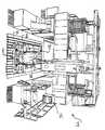
도면에서 동일한 부호는 동일하거나 대응하는 요소를 나타내며, 특히 도1에서 이중 목적 레이업 공구(30)는 지지 구조물(34)에 의해 지지된 상부판(32) 등의 공구 본체를 갖는 것으로 도시되어 있다. 상부판(32)은 화학 및 물리적 특성의 관점에서 그 부분의 구성 재료와 양립되는 재료로 제조된다. 예를 들어, 상부판(32)은 구성 재료, 특히 상부판에 접촉하여 위치한 층(대개는 "공구측 표층"이라 함)의 열팽창 계수에 일치하는 열팽창 계수를 갖는 것이 바람직하다. 공구측 표층이 통상적으로 사용되는 재료인 에폭시 수지로 예비 충전된 카본 파이버 직물인 경우에, 상부판(32)은 카본 파이버/에폭시 수지 합성재료로 되거나 또는 카본 파이버/에폭시 수지 합성재료의 열팽창 계수와 일치하는 열팽창 계수를 갖는 니켈 및 철 합금, 불변강(36)으로 될 수도 있다. 알루미늄 벌집형 코어를 갖춘 알루미늄 표층은 열팽창계수(CTE)가 거의 일치하고 알루미늄 구성 재료와 화학적으로 양립 가능한 알루미늄 공구를 사용한다.The same reference numbers in the figures represent the same or corresponding elements, in particular in FIG. 1 the dual
지지 구조물(34)은 양호한 실시예에서는 도1에 도시된 종래의 "계란 상자"구조를 취하지만, 임의의 적절한 구조를 취할 수 있다. 적절한 형태의 또 다른 지지 구조물로는 미국 특허 제5,100,255호에 개시된 부속품들과 함께 부착된 합성재료 튜브로 제조될 수 있으며, 상기 특허는 본 명세서에 참조된다. 지지 구조물(34)은 공장에서 공구(30)의 이동을 용이하게 해주도록 이송 보조구를 갖는다. 양호한 실시예에서의 이송 보조구는 공장 주변에서 공구(30)를 상승 및 이송하기 위해서 오버헤드 크레인의 후크에 결합되는 리프팅 케이블의 부착을 위하여 지지 구조물(34)의 전방 및 후방측에 각각 체결된 리프트 링(36)을 포함한다. 리프트 링(36)의 위치에 사용할 수 있거나 또는 이들에 추가로 사용할 수 있는 또 다른 이송 보조구는 도1에 도시된 것처럼 지지 구조물(34) 안에 설치된 포크 리프트 튜브(40)가 있다. 포크 리프트 튜브(40)는 공구(30)가 공장 주변에서 상승 및 이동되게 되는 포크 리프트의 이격된 분기부를 수용한다.The
도2에 도시된 5축 갠트리 공작기계(44) 등의 공작기계의 기부(42) 상에 공구(30)를 정확하게 인덱싱하여 위치시키기 위하여 그리고 소정 위치에서 지지 구조물(34)을 공작기계 베드(42)에 체결하기 위하여 위치결정 및 부착 장치가 지지 구조물(34) 상에 마련되어 있다. 공작기계 제어기(46)의 제어 하에서 공작기계(44)는 부품이 경화된 후에 공구(30) 상에 레이업된 부분 상에서 가공 작업을 수행한다. 위치결정 및 부착 장치는 공작기계 제어기가 공작기계를 부품의 정확한 가공을 위한 정확한 위치로 구동시킬 수 있도록 공구(30)를 베드(42) 상에 정확하게 위치시킨다. 위치결정 장치는 지점 설정기, 사인 키이 및 공구 볼을 포함하며, 이들의 사용에 대해서는 나중에 상세하게 설명한다. 이들 장치를 사용함으로써 공구(30)를 극도의 정확도로 공작기계의 기부(42) 상에 정확하게 위치시킬 수 있으며, 상기 위치를 점검하여 공구(30)의 상부판(34)의 정확한 위치에 일치시키도록 프로그램을 조정할 수 있으며, 이로써 공구(30)의 위치 및 그 위에 레이업된 부품이 공지의 정확도를 갖기 때문에 후속 가공 작동에서의 정확도를 유지할 수 있게 된다. In order to accurately index and position the
공구(30)가 공작기계 베드(42)에 고정되게 해주는 부착 장치는 작업편을 공작기계의 베드에 체결하는 기술 분야에 공지된 임의의 장치일 수 있다. 이 실시예에서, 부착 장치는 종래의 토우 클램프이며, 그 구조는 이 기술 분야에 공지되어 있다.The attachment device for securing the
상부판(32)은 그 부분의 구성 요소가 레이업되는 상부 상향 대면 표면(60)을 갖는다. 상부 표면(60)은 공구 상에 제조될 부품의 일 표면의 소정 형상에 일치하는 형상을 취한다. 상향 개방 리세스는 제조 공정 이후에 가공 작동이 요구될 부분 상의 위치에 대응하는 위치에서 상부판(32)의 상부 표면(60)으로 가공된다. 이 리세스는 부품의 둘레의 가장자리가 나중에 절단되게 되는 상부판(32) 상에 위치한 둘레의 홈(62)과, 부품을 관통하여 구멍이 드릴 가공되는 상부판(32) 상에 위치한 원통형 웰(well;63)을 포함한다. 다른 연속 홈들은 홈(62) 내에 위치하며, 여기서 개구들은 부품으로부터 절단된다. 여러 형상의 리세스 중 몇 개가 도6에 도시되어 있다. 리세스는 구성 재료가 상부 표면(60)의 높이와 일치하는 상부판(32) 상에 레이업될 수 있게 되는 희생 재료(64)를 수용한다.
홈(62)은 도3에 도시된 단면으로 도브테일형을 취하는 것이 바람직하며, 이는 희생 포움 재료가 제거될 때까지 이를 홈에 보유하는 것을 도와준다. 경화 후에, 포움 재료는 정상 환경 하에서 공구측 플라이를 공구 상부판(32)의 표면과 같은 높이로 유지하는 지지 표면을 제공하기에 충분한 강도인 약 35.15 kg/cm2 (500 psi)인 강도를 갖는다. 그러나, 더 큰 강도가 필요한 경우에는, 경화되었을 때 넓은 표면에 걸쳐 하중을 분배시켜서 큰 하중을 지탱할 수 있는 더 큰 강성 표면을 제공하도록 포움 재료(64)위에 한 겹 이상의 그래파이트/에폭시 예비 충전 테이프를 홈(62)에 부가할 수 있다. 부품의 제거 후에 홈(62)으로부터 포움 재료(64)의 제거가 용이하도록 수지 충전 직물로 된 별도의 스트립이 포움 재료를 홈 안에 인가하기 전에 홈(62) 안에 삽입된다.The
홈(62)은 부품의 구성 요소가 레이업될 상부판(32)의 대면 표면(60)의 중심부 주위로 가장자리 트림 네트가 위치하게 되는 표면 영역에서 완전히 연장된다. 다른 리세스는 부품을 통해서 구멍들이 드릴 가공되거나 부품을 통해서 다른 가공이 요구되는 공구 상의 영역에 위치한다. 외부둘레의 홈은 그것이 부품이 레이업되는 영역을 완전히 둘러싼다는 의미에서 연속적인 홈이라 할 수 있다. 그러나, 특정 부품의 설계는 홈에 단절부 또는 갭을 요할 수 있으며 이로써 "대체로 연속"인 홈을 이루게 된다. 바람직하게는, 홈은 밀 커터(68)의 둘레의 절단 톱니가 부품의 둘레의 가장자리의 전체 두께에 결합되어 절단할 수 있도록 밀 커터(68)가 이의 절단 경로 중에 대면 표면(60) 아래로 연장되기에 충분한 깊이를 취한다. 이 실시예에서의 홈(62)의 깊이(D)는 약 0.127 cm (0.050 inch)이지만, 커터(68)가 장착되는 공작기계가 필요한 정확도로 상부판(32)의 형상을 따르도록 프로그램될 수 없으면 홈의 깊이는 더 깊을 수도 있다.The
홈(62)의 폭(W)은 커터(68)의 직경에 공작기계(44) 내의 커터(68)의 이동 경로에 필요한 공차를 더한 크기를 수용하도록 선택된다. 홈(62)의 추가의 폭이 희생 재료(64)에 결합된 레이업 재료의 공구측 표면을 고정 유지하기 위해 커터(68)에 의해 절단된 자국(kerf)의 양 측면에 마련되어서 부품이 절단 작업 중에 이동되지 않게 하여 절단 작업이 완료되어 부품이 공구(30)로부터 제거될 준비를 할 때까지 상부판(32) 상의 제위치에 고정 상태로 유지되게 해준다.The width W of the
희생 재료(64)는 홈(62)을 충전시키는 데 편리하게 사용할 수 있고 결합/경화 작업 중에 구성 재료를 지지하기에 충분한 강도, 온도 공차 및 다른 특성을 갖는 임의의 적절한 재료로 될 수 있다. 이 실시예에 사용된 양호한 재료는 B.F. Goodrich #PL657 열팽창성 자체 표층식 포움이다. 상기 재료는 홈(62) 내에 비드(bead)또는 절단 스트립으로서 인가되어 도4에 도시된 것처럼 매끄러운 성형 코울 시트(70)로 덮인다. 코울 시트(70)는 홈(62) 및 다른 리세스가 가공되기 전에 상부판(32)의 상부면 상에 직접 성형된 그래파이트/에폭시 수지 구조인 것이 바람직하며, 비어있는 진공 백(71)으로 덮인 상태에서 경화 사이클에서의 경화 온도까지 가열함으로써 경화된다. 진공 트랙(73)은 대개는 홈(62)이 상부판 표면(60)에서 가공되게 되는 경로의 양 측면을 따라 진공 백(71)의 가장자리를 공구에 대하여 밀봉하는 데 사용되는 밀봉 테이프의 비드를 위치시킴으로써 코울 시트(70)의 하측면에 성형될 수 있다. 코울 시트가 제조되는 그래파이트/에폭시 시트는 테이프의 비드 위에서 공구면(60) 상에 위치하여 진공 트랙(73)을 형성하는 형상으로 경화된다. 희생 재료(64)는, 코울 시트(70)와 진공 백으로 홈(62)을 덮고 진공 백의 가장자리를 상부판(32)의 대면 표면(60)에 대하여 이 목적에 공지되어 있는 퍼티형 밀봉 테이프(75)로 밀봉시킴으로써 홈 내에서 팽창되고 경화된다. 진공 백은 약 25.4 cm (10 inch)의 진공으로 되며, 이 진공은 진공 트랙(73)에 인가되어 포움이 홈(62) 위에서 코울 시트의 하측면에 대하여 팽창되고 팽창된 상태에서 경화되는 동안에 코울 시트를 홈(62) 위에서 공구의 상부면(60)에 대하여 고정하는 것을 도와준다. 포움을 팽창 및 경화시키기 위해서는 공구(30)가 오븐 또는 오토클레이브 내에 위치하여 포움 재료 공급원에 의해 특정된 온도까지 가열되며, B.F. Goodrich #PL657 재료에 대한 상기 온도는 약 90분 동안 약 260 이다.The
포움(64)을 경화시키는 양호한 기술은 도5에 도시된 전기적으로 가열된 코울 시트(72)를 사용하는 것이다. 코울 시트(72)는 홈(62) 위의 영역에서 코울 시트(72)의 상부면(76)에 체결되거나 코울 시트(72)가 제조될 때 그 안에 매립된 전기 가열 테이프(74)를 갖는다. 도5에 점선으로 부분적으로 도시된 단열 블랭킷(77)은 주변 공기에의 열 손실을 감소시키도록 코울 시트(72)의 상부 위에 놓여서 포움(64)이 경화되는 동안에 포움을 상승된 온도로 유지하는 데 필요한 전력을 낮출 수 있다. 가열 테이프에 인접한 온도 센서(78)는 도체(79)를 통해서 제어기(80)에 전달될 신호를 생성하며, 상기 제어기는 코울 시트(72)의 온도를 관찰하여 홈(62) 내의 포움(64)을 소정 경화 온도로 유지하도록 가열 테이프(74)에 전달될 전력원(82)으로부터의 전력을 조정한다. 전기적으로 가열된 코울 시트(72)는 포움 경화 사이클 중에 값비싼 오븐을 사용할 필요성을 없애주어 제조 공정에서의 비용을 줄일 수 있게 해준다.A preferred technique for curing the
포움(64)이 경화된 후에, 진공 백(71) 및 코울 시트(70, 72)는 제거되고, 해제 코팅이 홈(62)의 양 측면 상에서 공구면(60)에 인가되지만 홈(62) 내의 희생 포움 재료(64)에는 인가되지 않는다. 해제 코팅은 부품이 공구(30)로부터 포움을 제거하는 시간에 공구면에 부착되지 않게 해준다. 부품의 공구측 표층(85)의 플라이는 공구면(60)에 인가되고 홈(62)에 중첩되어 도3에 도시된 것처럼 홈 너머로 짧은 거리로 연장되어 잉여부 또는 연장부를 마련하게 된다. 부품이 벌집형 코어 샌드위치인 경우에, 벌집형 코어 요소(84)는 이 요소들 사이에 접착제 팽창성 포움을 갖고 공구측 플라이 상부의 제위치에 끼워진다. 홈(62)에 사용된 동일한 팽창성 포움 재료를 벌집형 요소(84)들을 함께 결합하는 데 사용할 수도 있다.After the
브리더 스트립(breather strip, 87)은 공구측 플라이(85)에 인접하게 위치하고, 진공 백(71)은 공구측 플라이(85) 및 벌집형 코어 요소(84) 등의 다른 부품들 위에 위치한다. 진공 백(71)의 둘레의 가장자리는 이 기술 분야에 공지되어 있는 밀봉 테이프(75) 등으로 홈(62)의 외측면 주위에서 공구면에 대하여 밀봉된다. 진공 백(71) 아래 및 밀봉 퍼티의 둘레 내측의 공간은 진공 라인(88)을 통해서 홈(62)에 인접한 공구의 진공 포트(90)에 연통하는 진공 펌프(86)에 의해 진공화 된다. 진공 포트 내의 체크 밸브(도시 생략)는 공구(30)가 오토클레이브(도시 생략)로 이송되는 동안에 진공을 유지한다. 오토클레이브에서, 진공 포트(90)는 진공원(86)에 재차 연결되고, 오토클레이브는 가압 및 가열되어 플라이 내에 예비 충전된 수지를 유동 및 경화시키고, 경화 수지로부터의 배출 가스는 진공 라인(88)을 통해서 배출된다.The breather strip 87 is located adjacent to the tool side ply 85 and the vacuum bag 71 is located above other components such as the tool side ply 85 and the
플라이 및 부품 내의 수지가 경화된 후에, 오토클레이브의 온도 및 압력은 RPT로 감소되고, 공구(30)는 공작기계 베드(42)에 이송된다. 공구(30)의 지지 구조물(34) 상의 후퇴 가능한 푸트(94)는 지지 구조물(34)의 하측면 상의 데이타 표면(96)과 공작기계 베드(42)를 결합하도록 후퇴된다. 이는 갠트리 장착 공작기계(44)의 이동을 제어하는 가공 프로그램에 공지되어 있는 거리로 공작기계 베드(42)로부터 공구(30)의 대면 표면(60)의 수직 위치를 형성한다. 후퇴 가능한 푸트(94)는 데이타 표면(96)과 상부판(32)의 상부면(60) 사이의 거리에 영향을 미치는 니크 또는 다른 손상으로부터 정확하게 접지된 데이타 표면(86)을 보호하도록 모든 다른 시간, 즉 공구(30)의 저장 및 이동 중에 그리고 표층 재료 및 공구(30) 상의 구성 재료의 레이업 중에 연장된 상태로 유지된다.After the resin in the ply and part has cured, the temperature and pressure of the autoclave are reduced to RPT and the
공작기계베드(42) 상의 공구(30)의 위치 및 방향은 도7 및 도8에 도시된 지점 설정기(98) 및 사인 키이(100)를 포함하는 위치결정 장치에 의해 이루어진다. 지점 설정기(98)는 용접 등에 의해 공구(30)의 지지 구조물(34)의 하측면에 고정된 판(102)과, 이 판(102) 내에 정확하게 드릴 가공되어 위치한 수직 구멍(104)을 포함한다. 대개는 5.08 cm (2 inch)의 직경을 갖는 정밀 접지핀(106)은 구멍(104) 안에 활주식으로 끼워지고 도2에 도시된 공작기계 베드(42) 내의 여러 동일한 크기의 구멍(108)중 하나에 끼워진다. 도7 및 도8에 도시된 사인 키이(100)는 판(102)처럼 지지 구조물(34)의 하측면에 고정된 판(110)을 포함한다. 작은 수직 구멍(112)은 정확하게 드릴 가공되어 판(110)에 위치하며, 대개는 13/16 inch의 직경을 갖는 정확하게 접지된 핀(114)을 밀착 활주식 끼움 상태로 수용하며, 상기 핀은 판(110) 너머로 하방 연장되어 구멍(108)이 중심 설정되게 되는 공작기계 기부(42)에서 T형 슬롯(116) 안에 끼워진다. 핀(106, 114)이 판(102, 110) 내의 제위치에 있으면, 구멍(108) 및 슬롯(116) 하방으로 연장되는 상태에서 공구(30)의 위치는 공작기계 기부(42) 상에 독특하게 위치한다. 이 위치는 핀들이 위치하게 되는 슬롯(116) 및 구멍(108)을 식별함으로써 공작기계 제어 프로그램에 입력된다. 이 정보는 공구 형상 데이타 세트 및 부품 형상 데이타 세트와 함께 공작기계 제어기(46)에 입력되어 공작기계 제어기가 소정의 절단 작업을 수행하도록 공작기계를 안내하기에 충분한 정보를 제공한다.The position and orientation of the
도9에는 디지탈 부품 데이타를 가장자리 루팅 및 구멍 드릴가공 등의 부품 상의 소정의 가공 작업을 수행할 수 있도록 공작기계(44)의 제어기에 의해 판독되어 사용될 수 있는 가공 지시 내용으로 변환하는 공정이 개략적으로 도시되어 있다. 마스터 컴퓨터(122) 상에 위치한 디지탈 부품 모델(120)은 부품 모델(120)을 사용하여 프로그램(124)을 만드는 NC 가공 프로그램 작성자에게 제공된다. 이 프로그램은 커터 형태, 스핀들 속도, 커터 공급 속도, 커터 깊이, 통로의 수 및 커터가 이동하게 되는 경로 등의 정보를 포함한다. NC 가공 프로그램은 포스트 프로세서(126)를 통해서 처리되어 공작기계 제어기(46)에 의해 판독될 수 있는 포맷 및 매체에 프로그램된다. 이 프로그램은 필요에 따라 저장 및 회복을 위하여 데이타 베이스 관리 시스템에 탑재된다. 이 프로그램은 공작기계 조작자가 부품을 만들 준비를 하였을 때 조작자에 의해 회복된다. 조작자는 상기 프로그램을 공작기계 제어기에 탑재하여 공작기계 기부(42) 상에 적절하게 장착되어 그 위치를 확인한 후에 부품 상에 절단 가공을 수행하도록 프로그램을 작동시킨다.Fig. 9 schematically illustrates the process of converting digital part data into machining instructions that can be read and used by the controller of the
몇몇 부품은 별도의 코어 조립체가 공구측 표층으로부터 멀리 이격되어 제조되고 한 번의 작업으로 공구측 표층 및 백측 표층에 정합 되고 함께 경화될 것을 요한다. 이러한 부품에서는 그래파이트 에폭시의 단일 플라이가 공구의 표면(60) 상에 위치하고 벌집형 코어 요소들이 공구측 플라이 상부에 위치한다. B.F. Goodrich #PL657 재료 등의 포움 재료 스트립은 포움 코어 요소들 사이에 삽입된다. 진공 백은 조립체 위에 위치하여 진공 펌프에 의해 배출된다. 공구는 오토클레이브 내에 위치하고 온도 및 압력은 경화 사이클 중에 상승된다. 공정을 거꾸로 수행하면, 벌집형 코어 요소가 홈 위에 위치하여 홈에 걸쳐져서 포움이 경화되기 전에 진공 백이 홈(62) 내의 포움을 오목하게 하는 것을 방지하도록 지지부를 제공하기 때문에 코울 시트를 사용하여 홈(62) 내의 포움을 별도로 경화시킬 필요가 없다. 코어 요소가 경화된 후에, 공구는 공작기계에 위치하여 공작기계 베드(42) 상에 장착되어 제위치에 인덱싱된다. 코어 요소는 사용될 부품의 필요한 절삭된 형상을 생성하도록 가공되며, 코어 요소의 둘레는 코어 요소를 공구로부터 제거하기 위해 둘레의 홈(62)을 따라 절단된다. 절삭 및 가공된 코어 요소는 제거되어 동일하거나 다른 공구의 공구측 표층에 장착된다. 백측 표층은 코어 요소 위에 인가되고, 진공 백은 공구 위에 위치하여 공구를 밀봉한다. 진공 백은 배출되고 공구는 양 표층을 동시에 경화시키도록 오토클레이브 내에 위치한다.Some parts require a separate core assembly to be manufactured away from the tool side surface layer, mated to the tool side surface and back side surface layer in one operation and cured together. In this part a single ply of graphite epoxy is placed on the
부품에 필요한 절삭 프로필을 생성하도록 코어 요소(84)를 가공하는 작업은 코어 요소의 소정 형상을 생성하는 데 효율적이고 정확한 기술이다. 그러나, 가공 작업이 완료된 후에, 특히 부품이 백측 표층이 경화될 때까지 공구에 부착된 경우에는 코어 쉘로부터 먼지 및 파편을 제거하는 작업이 어렵다. 코어 셀로부터 먼지 및 파편을 제거하는 작업을 용이하게 하기 위하여 도10에 도시된 진공 공구(130)가 코어 요소의 상부면 위로 활주한다. 진공 공구는 진공 호스(136)가 부착되는 피팅(134)을 갖는 후드(132)를 갖고 있다. 파이프(138)는 이의 개구를 교차하는 방향으로 후드(132)의 대향 측면에 장착되어 있다. 파이프는 후드의 개구 쪽으로 향한 일렬의 작은 구멍(140)을 가지며, 공기 가압 호스(144)에의 부착을 위한 단부에 있는 신속 분리 커플링(142)을 갖고 있다.Machining the
작동 시에, 진공 공구는 진공 청소기 등의 진공원으로부터의 진공 호스(136)에 연결되고, 공기 호스(144)는 커플링(142)에 연결된다. 후드는 그 개구가 벌집형 코어의 표면상에 있도록 위치되며, 구멍 열(140)을 통해서 송풍되는 공기는 먼지를 벌집형 셀 외부로부터 불어내고 진공 상태의 먼지가 섞인 공기는 진공 호스(136)를 통해서 후드(132)로부터 배출된다. 구멍(140)을 통해서 송풍된 공기의 비율은 진공원에 의해 진공 후드(132) 외부로 흡입된 공기의 비율보다 낮으며, 이로써 먼지가 후드(132) 외부로 송풍되지 않게 된다. 후드(132)의 전연을 따라 형성된 얕은 노치 세트는 공기가 후드 안에 흡입되게 해주어서 후드 내측에 후드를 코어 요소(84)의 표면 위로 이동시키는 것을 어렵게 할 수 있는 진공 상태가 생성되는 것을 방지한다.In operation, the vacuum tool is connected to a
따라서, 본 발명은 레이업 공구 상에 부품을 레이업 및 경화/결합하는 방법 및 장치를 제공하고, 부품이 원래의 공구 상에 원래의 위치에 유지되는 동안에 벌집형 코어를 절삭하고 부품을 트리밍 및 드릴 가공하는 수단을 제공함으로써 상기 목적을 달성할 수 있게 해준다. 종래 기술의 방법 및 장치에서의 모든 문제점은 본 발명에 의해 해소될 수 있으며, 이로써 특정 공차에 대해 상당히 개선된 제조 적응력이 생기고, 공구의 제조와 유지 및 보관 비용을 줄일 수 있다. 작은 공차 제조의 개선된 능력은 고정적인 공차를 갖고 제한된 조립체 등의 이렇게 큰 레이업 부품에 현대의 제조 기술을 처음으로 사용함으로써, 부품이 사용되는 조립체의 품질을 더욱 개선하고 비용을 감소시킬 수 있다.Accordingly, the present invention provides a method and apparatus for laying up and hardening / joining a part on a layup tool, cutting the honeycomb core and trimming the part while the part remains in its original position on the original tool. By providing a means for drilling, it is possible to achieve the above object. All problems with the prior art methods and apparatus can be solved by the present invention, which results in significantly improved manufacturing adaptability to certain tolerances and reduces the cost of manufacturing and maintaining and storing the tool. The improved capability of manufacturing small tolerances allows for the first use of modern manufacturing techniques for such large layup parts, such as limited assemblies, with fixed tolerances, thereby further improving the quality and reducing the cost of the assembly in which the parts are used. .
이 기술분야에 숙련된 자는 상기에 설명한 실시예를 여러 형태로 변경 및 수정할 수 있다. 따라서, 이들 변경 및 수정 실시예와 그 균등물은 첨부한 청구범위에 기재된 본 발명의 기술사상 및 범위에 속한다.Those skilled in the art can change and modify the embodiments described above in various forms. Accordingly, these modified and modified examples and their equivalents fall within the spirit and scope of the invention as set forth in the appended claims.
도1은 본 발명에 따른 이중 목적 레이업 공구의 사시도.1 is a perspective view of a dual purpose layup tool according to the present invention;
도2는 갠트리가 장착된 공작기계의 기부에 인덱싱된 이중 목적 레이업 공구의 사시도.2 is a perspective view of a dual purpose layup tool indexed at the base of a machine tool with a gantry mounted thereon.
도3은 일부 요소가 인가된 상태로 도시한 도1에 도시된 공구의 상부판의 공구면의 단면도로서, 공구 상의 원래 위치에 장착되어 있는 동안에 상기 부분 상에서의 트리밍 및 다른 가공 작업 시에 커터 이동 경로를 도시한 도면.FIG. 3 is a cross-sectional view of the tool surface of the top plate of the tool shown in FIG. 1 with some elements applied, with the cutter moving during trimming and other machining operations on the portion while mounted in its original position on the tool. FIG. A diagram showing a path.
도4는 도1에 도시된 공구의 상부판의 일부분을 도시한 단면도로서, 희생 재료가 홈 경화부에 있고 홈에 걸쳐 코울 시트가 위치한 것을 도시한 도면.FIG. 4 is a cross-sectional view of a portion of the top plate of the tool shown in FIG. 1, showing that the sacrificial material is in the groove hardened portion and the coul sheet is positioned over the groove;
도5는 본 발명에 따른 공구에 걸쳐 있는 전기적으로 가열된 코울 시트를 도시한 분해 사시도.5 is an exploded perspective view of an electrically heated cowl sheet spanning a tool according to the invention.
도6은 본 발명에 따른 공구의 또 다른 형태를 도시한 사시도로서, 여러 절결부를 위한 공구 상부판의 리세스를 도시한 도면.Figure 6 is a perspective view of another form of the tool according to the present invention, showing the recess of the tool top plate for various cutouts.
도7은 도1에 도시된 공구와 유사한 공구의 지지 구조물을 도시한 측면도.FIG. 7 is a side view of a support structure of a tool similar to the tool shown in FIG. 1; FIG.
도8은 도7에 도시된 공구 지지 구조물을 도시한 평면도.8 is a plan view of the tool support structure shown in FIG.
도9는 디지탈 부품 모델로부터 공작기계 제어기에 의해 사용 가능한 형태로 디지탈 데이타를 변환하는 공정을 도시한 블럭도.9 is a block diagram illustrating a process of converting digital data from a digital part model into a form usable by a machine tool controller.
도10은 도1에 도시된 공구 상에 가공된 벌집형 코어 요소의 셀로부터 먼지를 세척하기 위한 진공 공구의 사시도.10 is a perspective view of a vacuum tool for cleaning dust from the cells of the honeycomb core element machined on the tool shown in FIG.
<도면의 주요 부분에 대한 부호의 설명><Description of the code | symbol about the principal part of drawing>
30: 레이업 공구30: Lay-up Tool
32: 상부판32: top plate
34: 지지 구조물34: support structure
36: 리프트 링36: lift ring
42: 공작기계 베드42: machine tool bed
44: 공작기계44: machine tool
46: 공작기계 제어기46: machine tool controller
62: 홈62: home
70: 코울 시트70: cotton sheet
71: 진공 백71: vacuum bag
73: 진공 트랙73: vacuum track
74: 가열 테이프74: heating tape
78: 온도 센서78: temperature sensor
84: 코어 요소84: core element
85: 공구측 표층85: tool side surface layer
86: 진공원86: vacuum source
132: 후드132: hood
Claims (16)
Translated fromKoreanApplications Claiming Priority (2)
| Application Number | Priority Date | Filing Date | Title |
|---|---|---|---|
| US08/629,120US5746553A (en) | 1996-04-08 | 1996-04-08 | Dual purpose lay-up tool |
| US08/629,120 | 1996-04-08 |
Publications (2)
| Publication Number | Publication Date |
|---|---|
| KR970069310A KR970069310A (en) | 1997-11-07 |
| KR100469876B1true KR100469876B1 (en) | 2005-03-16 |
Family
ID=24521661
Family Applications (1)
| Application Number | Title | Priority Date | Filing Date |
|---|---|---|---|
| KR1019970012788AExpired - Fee RelatedKR100469876B1 (en) | 1996-04-08 | 1997-04-08 | Dual purpose lay-up tool |
Country Status (6)
| Country | Link |
|---|---|
| US (1) | US5746553A (en) |
| EP (1) | EP0807504B1 (en) |
| KR (1) | KR100469876B1 (en) |
| CN (1) | CN1098152C (en) |
| CA (1) | CA2201981C (en) |
| DE (1) | DE69715959T2 (en) |
Families Citing this family (74)
| Publication number | Priority date | Publication date | Assignee | Title |
|---|---|---|---|---|
| CN1104974C (en)* | 1997-05-06 | 2003-04-09 | 波音公司 | Hybrid lay-up tool |
| US6284089B1 (en)* | 1997-12-23 | 2001-09-04 | The Boeing Company | Thermoplastic seam welds |
| SE519268C2 (en)* | 1999-12-23 | 2003-02-11 | Saab Ab | Device for holding an article and plant for heat treating an article |
| US6510601B1 (en)* | 2000-03-20 | 2003-01-28 | The Boeing Company | Invar forming method for making tooling |
| JP4318381B2 (en)* | 2000-04-27 | 2009-08-19 | 本田技研工業株式会社 | Manufacturing method of fuselage structure made of fiber reinforced composite material, and fuselage structure manufactured thereby |
| US6681466B2 (en) | 2001-05-09 | 2004-01-27 | United Air Lines, Inc. | Router replacement method |
| GB0127232D0 (en)* | 2001-11-13 | 2002-01-02 | Bae Systems Plc | A datum system for use in moulding operations |
| US7137182B2 (en)* | 2002-11-22 | 2006-11-21 | The Boeing Company | Parallel configuration composite material fabricator |
| US8336596B2 (en)* | 2002-11-22 | 2012-12-25 | The Boeing Company | Composite lamination using array of parallel material dispensing heads |
| US7141191B2 (en)* | 2003-05-02 | 2006-11-28 | The Boeing Company | Triple purpose lay-up tool |
| US20080149267A1 (en)* | 2006-12-26 | 2008-06-26 | Taylor Made Golf Company, Inc. | Methods for fabricating composite face plates for use in golf clubs and club-heads for same |
| US7874936B2 (en)* | 2007-12-19 | 2011-01-25 | Taylor Made Golf Company, Inc. | Composite articles and methods for making the same |
| US7236625B2 (en)* | 2003-07-28 | 2007-06-26 | The Boeing Company | Systems and method for identifying foreign objects and debris (FOD) and defects during fabrication of a composite structure |
| US7080441B2 (en)* | 2003-07-28 | 2006-07-25 | The Boeing Company | Composite fuselage machine and method of automated composite lay up |
| US7138031B2 (en)* | 2003-09-09 | 2006-11-21 | The Boeing Company | Mandrel and method for manufacturing composite structures |
| US7294220B2 (en)* | 2003-10-16 | 2007-11-13 | Toyota Motor Sales, U.S.A., Inc. | Methods of stabilizing and/or sealing core material and stabilized and/or sealed core material |
| US7228611B2 (en)* | 2003-11-18 | 2007-06-12 | The Boeing Company | Method of transferring large uncured composite laminates |
| US7289656B2 (en)* | 2003-12-02 | 2007-10-30 | The Boeing Company | Systems and methods for determining inconsistency characteristics of a composite structure |
| US8934702B2 (en)* | 2003-12-02 | 2015-01-13 | The Boeing Company | System and method for determining cumulative tow gap width |
| US7039485B2 (en) | 2004-03-12 | 2006-05-02 | The Boeing Company | Systems and methods enabling automated return to and/or repair of defects with a material placement machine |
| US7134629B2 (en)* | 2004-04-06 | 2006-11-14 | The Boeing Company | Structural panels for use in aircraft fuselages and other structures |
| US7159822B2 (en)* | 2004-04-06 | 2007-01-09 | The Boeing Company | Structural panels for use in aircraft fuselages and other structures |
| US7527222B2 (en) | 2004-04-06 | 2009-05-05 | The Boeing Company | Composite barrel sections for aircraft fuselages and other structures, and methods and systems for manufacturing such barrel sections |
| US7193696B2 (en)* | 2004-04-12 | 2007-03-20 | United Technologies Corporation | Systems and methods for using light to indicate defect locations on a composite structure |
| US7325771B2 (en) | 2004-09-23 | 2008-02-05 | The Boeing Company | Splice joints for composite aircraft fuselages and other structures |
| US7424902B2 (en)* | 2004-11-24 | 2008-09-16 | The Boeing Company | In-process vision detection of flaw and FOD characteristics |
| US7503368B2 (en) | 2004-11-24 | 2009-03-17 | The Boeing Company | Composite sections for aircraft fuselages and other structures, and methods and systems for manufacturing such sections |
| US20060108048A1 (en)* | 2004-11-24 | 2006-05-25 | The Boeing Company | In-process vision detection of flaws and fod by back field illumination |
| US20060118244A1 (en)* | 2004-12-02 | 2006-06-08 | The Boeing Company | Device for laying tape materials for aerospace applications |
| US7624488B2 (en)* | 2004-12-07 | 2009-12-01 | The Boeing Company | One-piece barrel assembly cart |
| ATE462553T1 (en)* | 2004-12-30 | 2010-04-15 | Airbus Espana Sl | METHOD FOR PRODUCING WEIGHT REDUCTION OPENINGS IN PLANAR SURFACES OF PRE-IMPREGNATED COMPOSITE PARTS BY PULLING PRESSING |
| ES2276569B1 (en)* | 2004-12-30 | 2008-06-16 | Airbus España S.L. | USEFUL HYBRID FOR THE CURING OF COMPOSITE MATERIAL PARTS. |
| US7889907B2 (en)* | 2005-01-12 | 2011-02-15 | The Boeing Company | Apparatus and methods for inspecting tape lamination |
| US7278198B2 (en)* | 2005-02-01 | 2007-10-09 | The Boeing Company | Mandrel segment loader |
| US7748119B2 (en)* | 2005-06-03 | 2010-07-06 | The Boeing Company | Method for manufacturing composite components |
| ES2274701B1 (en)* | 2005-07-15 | 2008-05-01 | GAMESA INNOVATION & TECHNOLOGY, S.L. | MANUFACTURING PROCEDURE FOR HUGE PIECES OF LARGE DIMENSIONS BASED ON COMPOSITE MATERIALS. |
| US7435947B2 (en)* | 2005-10-31 | 2008-10-14 | The Boeing Company | Apparatus and methods for integrating encoding functions in material placement machines |
| US7372556B2 (en)* | 2005-10-31 | 2008-05-13 | The Boeing Company | Apparatus and methods for inspecting a composite structure for inconsistencies |
| US7398586B2 (en)* | 2005-11-01 | 2008-07-15 | The Boeing Company | Methods and systems for manufacturing a family of aircraft wings and other composite structures |
| DE102006021110B4 (en)* | 2006-05-05 | 2011-04-21 | Airbus Operations Gmbh | Apparatus and method for producing a large-scale fiber composite structural component |
| DE102006050432B4 (en)* | 2006-08-11 | 2010-10-07 | MV Marketing und Vertriebs-GmbH & Co. KG Wieländer + Schill | drilling |
| WO2008049975A1 (en)* | 2006-10-23 | 2008-05-02 | Constructions Industrielles De La Mediterranee - Cnim | Composite tool for moulding cylindrical parts |
| US8337654B2 (en) | 2007-05-11 | 2012-12-25 | The Boeing Company | Configurable tooling and molding method using the same |
| US9579856B2 (en) | 2007-05-11 | 2017-02-28 | The Boeing Company | Methods and apparatus for molding and joining composite parts |
| US8388795B2 (en) | 2007-05-17 | 2013-03-05 | The Boeing Company | Nanotube-enhanced interlayers for composite structures |
| US20090035412A1 (en)* | 2007-07-31 | 2009-02-05 | Sobcinski Thomas J | Hybrid lay-up tool |
| US7968021B2 (en)* | 2007-07-31 | 2011-06-28 | The Boeing Company | Coefficient of thermal expansion control structure |
| US8042767B2 (en)* | 2007-09-04 | 2011-10-25 | The Boeing Company | Composite fabric with rigid member structure |
| US8196452B2 (en) | 2008-03-27 | 2012-06-12 | The Boeing Company | Collection of process data using in-situ sensors |
| DE102008028076A1 (en)* | 2008-06-13 | 2009-12-17 | Claas Fertigungstechnik Gmbh | Tool, and method for producing a tool, in particular for producing fiber-reinforced components |
| US8298473B2 (en)* | 2009-05-15 | 2012-10-30 | The Boeing Company | Method of making a cure tool with integrated edge breather |
| US8961732B2 (en) | 2011-01-03 | 2015-02-24 | The Boeing Company | Method and device for compressing a composite radius |
| US8460502B2 (en) | 2011-04-14 | 2013-06-11 | Spirit Aerosystems, Inc. | Method and tooling for manufacture of co-cured composite structures |
| DE102011079928A1 (en)* | 2011-07-27 | 2013-01-31 | Airbus Operations Gmbh | Device for producing an adhesive component with fiber-reinforced plastics and method |
| FR2991628A1 (en)* | 2012-06-12 | 2013-12-13 | Aircelle Sa | TOOL ASSEMBLY FOR MANUFACTURING COMPOSITE WORKPIECE AND METHOD FOR MANUFACTURING COMPOUND PIECE. |
| EP2796373B1 (en) | 2013-04-25 | 2015-12-09 | Airbus Operations GmbH | Assembling jig for mounting panel structure elements onto a surface of a CFRP-panel |
| US9861864B2 (en) | 2013-11-27 | 2018-01-09 | Taylor Made Golf Company, Inc. | Golf club |
| US9511519B2 (en)* | 2014-02-04 | 2016-12-06 | The Boeing Company | System and method of vacuum bagging composite parts |
| US9597843B2 (en) | 2014-05-15 | 2017-03-21 | The Boeing Company | Method and apparatus for layup tooling |
| US9579855B2 (en)* | 2014-12-15 | 2017-02-28 | Spirit Aerosystems, Inc. | Secondary groove for work piece retention during machining |
| US9902091B2 (en)* | 2015-04-21 | 2018-02-27 | Rohr, Inc. | Composite bonding tool with high thermal conductivity and low coefficient of thermal expansion |
| US10399285B2 (en) | 2016-02-08 | 2019-09-03 | Bell Helicopter Textron Inc. | Composite wing structure and methods of manufacture |
| US10513324B2 (en)* | 2016-02-08 | 2019-12-24 | Bell Helicopter Textron Inc. | Composite rib assembly |
| CN105773991A (en)* | 2016-03-25 | 2016-07-20 | 哈尔滨飞机工业集团有限责任公司 | Glue joint forming device and method of wing cover with small-curvature honeycomb structure |
| JP2020511334A (en)* | 2017-03-16 | 2020-04-16 | ザ・ボーイング・カンパニーThe Boeing Company | Method for co-joining a first thermosetting composite and a second thermosetting composite to form a cured composite part |
| US11701801B2 (en)* | 2019-03-04 | 2023-07-18 | The Boeing Company | Caul plate with feature for separating from composite part |
| CN111069697B (en)* | 2019-12-26 | 2021-04-30 | 济南北方金锋锯业有限公司 | Vertical sawing machine |
| CN111958886B (en)* | 2020-07-15 | 2022-06-07 | 天津爱思达航天科技有限公司 | Universal carbon foam composite material die with high yield and preparation method thereof |
| CN112571835B (en)* | 2020-10-30 | 2022-09-27 | 航天材料及工艺研究所 | An efficient teaching and programming process method suitable for automatic inclined laying |
| NL2027413B1 (en)* | 2021-01-26 | 2022-08-26 | Boeing Co | Indexing apparatus and method of indexing |
| JP2022080865A (en)* | 2020-11-18 | 2022-05-30 | ザ・ボーイング・カンパニー | Installation of indexing features on composite parts |
| JP2022096610A (en)* | 2020-11-18 | 2022-06-29 | ザ・ボーイング・カンパニー | Correspondence device and mapping method |
| EP4000895A1 (en) | 2020-11-18 | 2022-05-25 | The Boeing Company | Indexing apparatus and method of indexing |
| US20240165895A1 (en)* | 2022-11-17 | 2024-05-23 | The Boeing Company | Composite Manufacturing with Reduced Manufacturing Time |
Family Cites Families (17)
| Publication number | Priority date | Publication date | Assignee | Title |
|---|---|---|---|---|
| US4468160A (en)* | 1982-09-09 | 1984-08-28 | Campbell Automation, Incorporated | Woodworking machine |
| US4795518A (en)* | 1984-02-17 | 1989-01-03 | Burr-Brown Corporation | Method using a multiple device vacuum chuck for an automatic microelectronic bonding apparatus |
| US4680216A (en)* | 1984-09-04 | 1987-07-14 | United Technologies Corporation | Method for stabilizing thick honeycomb core composite articles |
| US4664737A (en)* | 1984-12-13 | 1987-05-12 | The Boeing Company | System for removably attaching blanket to composite material lay-up structure |
| US4786351A (en)* | 1985-12-31 | 1988-11-22 | Astechnologies, Inc. | Process and apparatus for simultaneously shaping foam and laminating fabric thereto |
| US4867829A (en)* | 1987-01-16 | 1989-09-19 | Takashimaya Nippatsu Kogyo Co., Ltd. | Process for producing interior vehicular trim |
| JPH0755467B2 (en)* | 1987-04-23 | 1995-06-14 | 株式会社川上製作所 | Cutting device for laminated sheet material |
| EP0365677A4 (en)* | 1988-03-18 | 1991-04-17 | Takai International Yacht Design Incorporated | Molding method and apparatus for laminated molded article |
| US4913639A (en)* | 1988-09-13 | 1990-04-03 | Wheeler Robert G | Composite caul plate |
| IL88626A0 (en)* | 1988-12-07 | 1989-07-31 | N C T Limited | Method and apparatus for making three-dimensional objects |
| AT396085B (en)* | 1990-07-13 | 1993-05-25 | Gfm Fertigungstechnik | DEVICE FOR TRIMMING SPATIAL MOLDINGS FROM PLASTIC OD. DGL. |
| US5145297A (en)* | 1990-11-07 | 1992-09-08 | Northrop Corporation | System and method for particulate matter removal |
| US5248551A (en)* | 1992-04-29 | 1993-09-28 | Davidson Textron Inc. | Bumper preform and method of forming same |
| US5413661A (en)* | 1992-05-13 | 1995-05-09 | R+S Stanztechnik Gmbh | Method for producing a laminated structural component with a hard foam reinforcement |
| US5242523A (en)* | 1992-05-14 | 1993-09-07 | The Boeing Company | Caul and method for bonding and curing intricate composite structures |
| US5411688A (en)* | 1992-06-29 | 1995-05-02 | Duotec Products Associates | Method for forming plastic molded panels with inserts |
| DE29507068U1 (en)* | 1995-04-27 | 1995-09-28 | Paul Kiefel GmbH, 83395 Freilassing | Device for cutting laminated cladding parts with ultrasound |
- 1996
- 1996-04-08USUS08/629,120patent/US5746553A/ennot_activeExpired - Lifetime
- 1997
- 1997-04-07CACA002201981Apatent/CA2201981C/ennot_activeExpired - Fee Related
- 1997-04-08CNCN97110333Apatent/CN1098152C/ennot_activeExpired - Fee Related
- 1997-04-08KRKR1019970012788Apatent/KR100469876B1/ennot_activeExpired - Fee Related
- 1997-04-08EPEP97201049Apatent/EP0807504B1/ennot_activeExpired - Lifetime
- 1997-04-08DEDE69715959Tpatent/DE69715959T2/ennot_activeExpired - Lifetime
Also Published As
| Publication number | Publication date |
|---|---|
| CA2201981A1 (en) | 1997-10-08 |
| DE69715959T2 (en) | 2003-01-30 |
| CN1168317A (en) | 1997-12-24 |
| EP0807504B1 (en) | 2002-10-02 |
| KR970069310A (en) | 1997-11-07 |
| CA2201981C (en) | 2005-11-29 |
| DE69715959D1 (en) | 2002-11-07 |
| US5746553A (en) | 1998-05-05 |
| CN1098152C (en) | 2003-01-08 |
| EP0807504A1 (en) | 1997-11-19 |
Similar Documents
| Publication | Publication Date | Title |
|---|---|---|
| KR100469876B1 (en) | Dual purpose lay-up tool | |
| KR100583036B1 (en) | Composite support tool | |
| US7141191B2 (en) | Triple purpose lay-up tool | |
| US8454280B2 (en) | Formation of a pattern of holes in a structure | |
| US6620369B1 (en) | Net molding of resin composite parts | |
| US11772339B2 (en) | Three-dimensional printing of composite repair patches and structures | |
| EP1231046A3 (en) | Method for manufacturing elements of composite materials by the cobonding technique | |
| EP1077804B1 (en) | Manufacture of stiffened composite structures | |
| CN112721232A (en) | Placing and compacting objects via vacuum | |
| EP4163076B1 (en) | Rapid tooling layup mandrel and method of moulding a part | |
| US12054292B2 (en) | Method for the assembly of frames in an aircraft shell | |
| US20210060874A1 (en) | Method for securing core to tool during machining | |
| EP3862172B1 (en) | Composite panel tooling system and method | |
| EP4371747A1 (en) | Method for forming a composite product | |
| JP2022080865A (en) | Installation of indexing features on composite parts | |
| GB2156262A (en) | Trimming fibre-reinforced plastics material | |
| Burpo et al. | Affordable Integrated Helicopter Fuselage Structure—Full-Scale Article |
Legal Events
| Date | Code | Title | Description |
|---|---|---|---|
| PA0109 | Patent application | St.27 status event code:A-0-1-A10-A12-nap-PA0109 | |
| R17-X000 | Change to representative recorded | St.27 status event code:A-3-3-R10-R17-oth-X000 | |
| P11-X000 | Amendment of application requested | St.27 status event code:A-2-2-P10-P11-nap-X000 | |
| P13-X000 | Application amended | St.27 status event code:A-2-2-P10-P13-nap-X000 | |
| PG1501 | Laying open of application | St.27 status event code:A-1-1-Q10-Q12-nap-PG1501 | |
| A201 | Request for examination | ||
| P11-X000 | Amendment of application requested | St.27 status event code:A-2-2-P10-P11-nap-X000 | |
| P13-X000 | Application amended | St.27 status event code:A-2-2-P10-P13-nap-X000 | |
| PA0201 | Request for examination | St.27 status event code:A-1-2-D10-D11-exm-PA0201 | |
| E902 | Notification of reason for refusal | ||
| PE0902 | Notice of grounds for rejection | St.27 status event code:A-1-2-D10-D21-exm-PE0902 | |
| T11-X000 | Administrative time limit extension requested | St.27 status event code:U-3-3-T10-T11-oth-X000 | |
| P11-X000 | Amendment of application requested | St.27 status event code:A-2-2-P10-P11-nap-X000 | |
| P13-X000 | Application amended | St.27 status event code:A-2-2-P10-P13-nap-X000 | |
| E701 | Decision to grant or registration of patent right | ||
| PE0701 | Decision of registration | St.27 status event code:A-1-2-D10-D22-exm-PE0701 | |
| GRNT | Written decision to grant | ||
| PR0701 | Registration of establishment | St.27 status event code:A-2-4-F10-F11-exm-PR0701 | |
| PR1002 | Payment of registration fee | St.27 status event code:A-2-2-U10-U11-oth-PR1002 Fee payment year number:1 | |
| PG1601 | Publication of registration | St.27 status event code:A-4-4-Q10-Q13-nap-PG1601 | |
| R18-X000 | Changes to party contact information recorded | St.27 status event code:A-5-5-R10-R18-oth-X000 | |
| PN2301 | Change of applicant | St.27 status event code:A-5-5-R10-R11-asn-PN2301 | |
| PR1001 | Payment of annual fee | St.27 status event code:A-4-4-U10-U11-oth-PR1001 Fee payment year number:4 | |
| PR1001 | Payment of annual fee | St.27 status event code:A-4-4-U10-U11-oth-PR1001 Fee payment year number:5 | |
| PR1001 | Payment of annual fee | St.27 status event code:A-4-4-U10-U11-oth-PR1001 Fee payment year number:6 | |
| PR1001 | Payment of annual fee | St.27 status event code:A-4-4-U10-U11-oth-PR1001 Fee payment year number:7 | |
| FPAY | Annual fee payment | Payment date:20120110 Year of fee payment:8 | |
| PR1001 | Payment of annual fee | St.27 status event code:A-4-4-U10-U11-oth-PR1001 Fee payment year number:8 | |
| LAPS | Lapse due to unpaid annual fee | ||
| PC1903 | Unpaid annual fee | St.27 status event code:A-4-4-U10-U13-oth-PC1903 Not in force date:20130126 Payment event data comment text:Termination Category : DEFAULT_OF_REGISTRATION_FEE | |
| PC1903 | Unpaid annual fee | St.27 status event code:N-4-6-H10-H13-oth-PC1903 Ip right cessation event data comment text:Termination Category : DEFAULT_OF_REGISTRATION_FEE Not in force date:20130126 | |
| P22-X000 | Classification modified | St.27 status event code:A-4-4-P10-P22-nap-X000 |