KR100446264B1 - Manufacturing method of electrochemical measuring sensor and electrochemical measuring sensor - Google Patents
Manufacturing method of electrochemical measuring sensor and electrochemical measuring sensorDownload PDFInfo
- Publication number
- KR100446264B1 KR100446264B1KR1019970704588AKR19970704588AKR100446264B1KR 100446264 B1KR100446264 B1KR 100446264B1KR 1019970704588 AKR1019970704588 AKR 1019970704588AKR 19970704588 AKR19970704588 AKR 19970704588AKR 100446264 B1KR100446264 B1KR 100446264B1
- Authority
- KR
- South Korea
- Prior art keywords
- electrode
- solid electrolyte
- measuring sensor
- electrochemical measuring
- gas
- Prior art date
- Legal status (The legal status is an assumption and is not a legal conclusion. Google has not performed a legal analysis and makes no representation as to the accuracy of the status listed.)
- Expired - Fee Related
Links
Images


Classifications
- G—PHYSICS
- G01—MEASURING; TESTING
- G01N—INVESTIGATING OR ANALYSING MATERIALS BY DETERMINING THEIR CHEMICAL OR PHYSICAL PROPERTIES
- G01N27/00—Investigating or analysing materials by the use of electric, electrochemical, or magnetic means
- G01N27/26—Investigating or analysing materials by the use of electric, electrochemical, or magnetic means by investigating electrochemical variables; by using electrolysis or electrophoresis
- G01N27/403—Cells and electrode assemblies
- G01N27/406—Cells and probes with solid electrolytes
- G01N27/407—Cells and probes with solid electrolytes for investigating or analysing gases
- G01N27/4075—Composition or fabrication of the electrodes and coatings thereon, e.g. catalysts
Landscapes
- Chemical & Material Sciences (AREA)
- Life Sciences & Earth Sciences (AREA)
- Health & Medical Sciences (AREA)
- Physics & Mathematics (AREA)
- Chemical Kinetics & Catalysis (AREA)
- Electrochemistry (AREA)
- Molecular Biology (AREA)
- Analytical Chemistry (AREA)
- Biochemistry (AREA)
- General Health & Medical Sciences (AREA)
- General Physics & Mathematics (AREA)
- Immunology (AREA)
- Pathology (AREA)
- Measuring Oxygen Concentration In Cells (AREA)
Abstract
Translated fromKoreanDescription
Translated fromKorean상기 개념에 의한 종류의 전기화학적 측정센서는 공지되어 있다. 이 전기화학적 측정센서는 일반적으로 층상구조를 가지며, 상기의 경우에 지지체로서도 기능하는 고체전해질은 대향하는 측부에 전극을 각각 한 개씩 가지고 있다. 이들 전극의 한 쪽은 측정가스에 노출되어 있고, 다른 쪽의 전극은 기준가스(reference gas), 일반적으로 공기에 노출되어 있다. 측정가스 중의 산소함량에 상응하여 측정가스에 대향한 전극에는 일정한 산소 분압이 생긴다. 이 산소 분압은 기준가스로부터 출발하여 이 기준가스에 대향한 전극에 생기는 산소 분압에 대하여 일정한 비율이다. 이것들의 양쪽 전극에 생기는 산소 농도 차이에 기초하여 양쪽 전극간에 일정한 검출전압이 생기고, 이 검출전압은 적당한 평가회로를 사용하여 평가하는 것이 가능하고, 나아가서는 측정가스에 노출되는 전극에 존재하는 산소 농도는 상응하는 신호를 공급한다. 이 종류의 화학적 측정센서는, 예를 들면 독일연방공화국 특허출원 공개 제 2928496호 명세서의 기재에 공지되어 있다. 상기의 경우 기준가스에 노출되는 전극에는 피복이 구비되어 있다. 이 피복된 전극에 대향한 측부는전극으로의 기준가스의 공급을 가능하게 하는 홈형상 구조를 가지고 있다. 따라서 화학적 측정센서는 일반적으로 공지된 소결법에 의해 상호 견고히 결합되는, 상대적으로 다수의 개개의 층으로 이루어진 구조를 가지고 있다, 전기화학적 측정센서의 공지된 구조인 경우에, 기준가스와 직접적으로 접촉하는 유효한 전극면적은 실제의 전극면적과 비교하여 상대적으로 작다는 결점을 가지고 있다.Electrochemical measuring sensors of the kind according to the above concept are known. This electrochemical measuring sensor generally has a layered structure, and in this case, the solid electrolyte, which also functions as a support, has one electrode on the opposite side. One of these electrodes is exposed to the measurement gas and the other electrode is exposed to a reference gas, typically air. According to the oxygen content in the measurement gas, a constant oxygen partial pressure is generated at the electrode facing the measurement gas. This partial pressure of oxygen starts at a reference gas and is a constant ratio with respect to the partial pressure of oxygen generated at the electrode facing the reference gas. Based on the difference in oxygen concentration generated at both electrodes, a constant detection voltage is generated between the electrodes, and this detection voltage can be evaluated using an appropriate evaluation circuit, and furthermore, the oxygen concentration present at the electrode exposed to the measurement gas. Supplies the corresponding signal. Chemical measuring sensors of this kind are known, for example, from the description of the German Patent Application Publication No. 2928496. In the above case, the electrode exposed to the reference gas is provided with a coating. The side portion opposite to the coated electrode has a groove-shaped structure that enables supply of a reference gas to the electrode. Therefore, the chemical sensor generally has a structure composed of a relatively large number of individual layers, which are firmly bonded to each other by a known sintering method. In the case of the known structure of the electrochemical sensor, the chemical sensor directly contacts the reference gas. The effective electrode area has the drawback that it is relatively small compared with the actual electrode area.
본 발명은, 청구항 1의 상위개념에 기재된 전기화학적 측정센서 및 청구항 6의 상위개념에 기재된 전기화학적 측정센서의 제조방법에 관한 것이다.The present invention relates to an electrochemical measuring sensor described in a higher concept of claim 1 and a method of manufacturing the electrochemical measuring sensor described in a higher concept of claim 6.
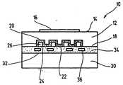
도 1은, 한 개의 전기화학적 측정센서를 나타내는 개략적인 단면도.1 is a schematic cross-sectional view showing one electrochemical measuring sensor.
도 2는, 기준가스에 노출되는 전극을 나타내는 사시도.2 is a perspective view showing an electrode exposed to a reference gas;
도 3은, 다른 실시예에 의하여 측정가스에 노출되는 전극을 나타내는 평면도.3 is a plan view showing an electrode exposed to a measurement gas according to another embodiment.
청구항에 기재된 특징을 가지는 본 발명에 의한 전기화학적 측정센서는, 비교적 큰 유효 전극면적이 사용된다고 하는 이점을 제공한다. 측정가스 또는 기준가스에 노출되는 측부에서 전극의 적어도 한 개가 윤곽부(contouring)를 나타내는 것에 따라, 외측부의 크기가 불변인 그대로인 전기화학적 센서인 경우에는 전극면적의 확대는 간단한 방법으로 가능하다. 특히 홈형상 패턴으로써 형성되는 윤곽부에 의해서 전극의 표면적은 확대될 수 있고, 따라서 전극의 상응하는 높은 전극 활성, 예를 들면 높은 여기 효율(pumping output)이 제공된다.The electrochemical measuring sensor according to the invention having the features described in the claims provides the advantage that a relatively large effective electrode area is used. As at least one of the electrodes is contoured at the side exposed to the measurement gas or the reference gas, in the case of an electrochemical sensor in which the size of the outer part remains unchanged, the electrode area can be enlarged by a simple method. The surface area of the electrode can be enlarged, in particular by means of the contour formed by the groove-shaped pattern, thus providing the corresponding high electrode activity of the electrode, for example high pumping output.
본 발명의 바람직한 실시형식의 경우에는, 기준가스 홈으로서 사용되는 네트워크가 생기는 홈형상 패턴의 윤곽부가 형성된 것이 설치되어 있다. 이것에 의하여 기준가스에 노출되는 전극 그 자체의 윤곽부에 의해서, 전기화학적 측정센서의 기준공기 통로를 가지는 부가적인 층을 배치하는 것이 이제는 불필요하므로, 극히 유리하게 달성된다. 이것에 의하여 전기화학적 측정센서의 구조는 단순화할 수 있다. 또한 부가적인 층을 생략함으로써 전기화학적 측정센서의 소형화가 가능하다.In the case of a preferred embodiment of the present invention, one having a contour portion of a groove pattern in which a network used as a reference gas groove is formed is provided. This is advantageously achieved, since it is no longer necessary to arrange an additional layer with a reference air passage of the electrochemical measuring sensor by the contour of the electrode itself, which is exposed to the reference gas. Thereby, the structure of the electrochemical measuring sensor can be simplified. It is also possible to miniaturize the electrochemical measuring sensor by omitting additional layers.
또한, 청구항 6에 기재된 특징을 가지는 전기화학적 측정센서를 제조하기 위한 본 발명에 의한 방법은, 대량생산에 알맞은 간단한 방법으로 간단하고 또한 튼튼한 구조를 나타내는 전기화학적 측정센서를 달성할 수 있다는 이점을 제공한다. 측정가스 또는 기준가스에 노출되는 측부의 전극의 적어도 한 개가 소결전에 윤곽부가 성형되는 것에 따라, 일면에서 유효한 전극면적의 확대를 위하여 윤곽부의 형성이 이용되고, 다른 면 전극 또는 전극을 가지는 측정센서의 높은 기계적 안정성이 달성되는 것이 유리하게 가능하고, 따라서 이 측정센서의 취급가능성은, 제조과정에서 뿐만 아니라 센서 소자중에 설치하는 경우에도 개선되어 있다.In addition, the method according to the present invention for producing an electrochemical measuring sensor having the features as claimed in claim 6 provides the advantage that an electrochemical measuring sensor exhibiting a simple and robust structure can be achieved by a simple method suitable for mass production. do. As at least one of the electrodes on the side exposed to the measuring gas or the reference gas is molded before sintering, the formation of the contour is used to enlarge the effective electrode area on one side, and the measurement of the measuring sensor having the other side electrode or electrode It is advantageously possible to achieve high mechanical stability, and therefore the handleability of this measuring sensor is improved not only in the manufacturing process but also in the installation in the sensor element.
윤곽부를 형성하기 위해 전극에 엠보싱(embossing) 가공하는 것이 특히 유리하다. 전기화학적 측정센서의 소결전에 전극에 엠보싱하는 것은, 간단한 방법으로 상응하는 엠보싱 플러그를 사용하여, 전극 또는 측정센서가 아직 소결되지 않고서, 소위 원래 그대로인 시트로서 존재하는 시점에서 가능하다. 따라서 이 전극 또는 측정센서는, 양호한 변형가능성을 가지며, 따라서 엠보싱에 의해 고도로 정확한 윤곽부가 달성가능하고, 이 윤곽부는 전기화학적 측정센서의 소결후에 얻어진 그대로 유지된다.It is particularly advantageous to emboss the electrodes to form contours. Embossing of the electrode before sintering of the electrochemical measuring sensor is possible at the point where the electrode or measuring sensor is present as a so-called intact sheet, without yet being sintered, using a corresponding embossing plug in a simple manner. This electrode or measuring sensor thus has a good deformability and therefore highly accurate contours are achievable by embossing, which contours remain as obtained after sintering of the electrochemical measuring sensor.
본 발명의 다른 바람직한 실시예는 종속청구항에 기재된 나머지의 특징으로부터 분명하다.Other preferred embodiments of the invention are apparent from the remaining features set forth in the dependent claims.
다음에, 본 발명을 실시예에서 첨부도면에 관하여 상세히 설명한다.Next, the present invention will be described in detail with reference to the accompanying drawings in the Examples.
도 1은 공통으로 부호 10으로서 표시한 전기화학적 측정센서를 나타내며, 이전기화학적 측정센서는, 예를 들면 가스 혼합물중, 특히 내연기관의 배기가스중의 산소 함량의 측정에 사용할 수 있다. 측정센서(10)는 고체전해질(12)로 이루어지고, 도 1의 고체전해질의 상방향에 표시한 측부(14)상에는 제1 전극(16)이 배치되어 있다. 고체전해질(12)의 다른 측부(18)에는 제2 전극(20)이 배치되어 있다. 이 경우 전극(20)은 고체전해질(12)중에 매설되어 있고, 따라서 전극(20)의 외측부(22)는 고체전해질(12)의 측부(18)와 동일한 열로 배치되어 있고, 또한 전체에 한개의 평평한 표면이 생긴다.Figure 1 shows an electrochemical measuring sensor, commonly denoted by
전극(20)은 횡단면에서 보아 구불구불한 연장부를 가지며, 그 구조를 상세히 설명한다. 전극(20)은 윤곽부(24)를 가지며, 이 윤곽부는 외측부(22)를 향하여 열린 홈형상 패턴(26)으로서 형성되어 있다. 홈형상 패턴(26)은 도 2에서 분명한 것처럼 망상구조(28)를 형성하고 있고, 상기 망상구조중에서 전극(20)을 따라서 연장되는 홈형상 패턴(26)은 전극(20)에 대하여 가로방향으로 배치된 홈형상 패턴(26)과 교차하고 있다.The
고체전해질(12)의 측부(18)는 덮개판(30)을 구비하고 있다. 홈형상 패턴(26)은 덮개판(30)에 의해서 전극(20)의 외측부(22)에서 폐쇄되어 있고, 따라서 분기한 통로계가 생긴다. 따라서 홈형상 패턴(26)은 3개의 측부에서 전극(20)에 의해서 제한되고 또한 제4의 측부에서 덮개판(30)에 의해서 제한되어 있다. 덮개판(30)중에는 경우에 따라 가열장치(32)가 구비되어 있어도 좋고, 이 경우에 층(34)중에는 가열도체(36)가 배치되어 있다.The
홈형상 패턴(26)은 측정센서(10)의 한 측부, 특히 측정센서(10)의 전면으로 열려 있고, 따라서 기준가스는 홈형상 패턴(26)으로써 형성된 네트워크 형상 통로계를 통하여 전극(20)에 이를 수 있다. 홈형상 패턴(26)이 3개의 측부에서 전극(20)에 의해서 포위되어 있는 것에 의해 기준가스와 직접적으로 접촉하는 전극(20)의 유효표면적은 비교적 크다. 나타낸 실시예에 있어서, 이 상대적인 표면전극(20)은 고체전해질(12)상에 평활하게 시행된 통상의 전극과 비교하여 3배의 가치가 있다.The
전기화학적 측정센서(10)를 위한 본 발명에 의한 제조방법은 도 2에 관하여 상세하게 설명된다. 도 1과 같은 부분은 같은 기준부호를 가지고 있고, 또 다시는 설명하지 않는다. 측정센서(10)를 완전히 도시하는 것은 일목요연하기 때문에 생략하였다.The manufacturing method according to the invention for the
고체전해질(12)이 본질적으로 판상인 것은 사시도에 관하여 분명하게 된다. 고체전해질(12)은, 예를 들면 이트륨에 의해 안정화된 산화 지르코늄으로 이루어지고, 또한 시트형상으로 존재한다. 고체전해질(12)의 상기 도 2의 상측부에 존재하는 측부(18)상에는 전극(20)이 장착된다. 전극(20)은 통상 공지의 처리과정, 예를 들면 인쇄에 의해서 장착된다. 이 경우, 전극(20)은 고체전해질(12)의 윤곽선상에 존재하고 있다. 고체전해질(12) 및 전극(20) 및 반대측부에 배치된, 이 경우에는눈으로 볼 수 없는 전극(16)은 또한 소위 원래 그대로의 시트로서 존재하며, 즉 이 전극은 아직 소결되어 있지 않다.It is evident with respect to the perspective that the
전극(20)은 전극두부(electrode head:38)를 가지며, 이 전극두부는 띠형상 도체로(40)에 걸쳐서 도시되어 있지 않은 회로장치와 접촉가능하다. 전극(20)을 고체전해질(12)상에 장착한 후 홈형상 패턴(26)으로써 형성된 네트워크(28)의 배치를 후에 나타내는 격자구조를 가지는 도 2에 도시된 엠보싱 스탬프(embossing stamp:42)를 사용하여 엠보싱되어 있다. 엠보싱 스탬프(42)에 엠보싱력을 주는 것에 따라 엠보싱 스탬프(42)의 격자구조는, 전극(20)중 및 부분적으로 고체전해질(12)중에 형성된다. 엠보싱력에 의해서, 동시에 전극(20)은 고체전해질(12)중으로 밀어 넣어지고, 따라서 도 1에 단면도에 도시된 경우와 같이, 고체전해질(12)중에 매설된 전극(20)을 가지는 구조가 생긴다. 엠보싱 스탬프(42)를 제거한 후, 전극(20)중에는 교차하는 홈형상 패턴(26)이 남아 있게 된다.The
엠보싱 과정에 계속해서, 전체의 전기화학적 측정센서(10)는 공지된 방법으로 소결되고, 따라서 개개의 층은 상호 견고히 결합되어 있다. 이 경우에는 측정센서(10), 및 측정센서(10)중 특히 전극(20)중에서 엠보싱된 홈형상 패턴(26)의 안정화는 동시에 행하여진다. 이 경우, 홈형상 패턴(26)은 측정센서(10)의 전면(44)에서 상기 전면이 도 1에 나타난 덮개판(30)에 의한 피복후에 구멍(46)을 가지도록 설계되어 있고, 따라서 기준가스는, 홈형상 패턴(26)으로써 형성된 통로망을 관류할 수 있다.Subsequent to the embossing process, the entire
전체적으로 전기화학적 측정센서(10)는, 극히 조밀한 구조를 가지며, 이 구조는 간단한 처리과정에 의해 달성된다. 이 경우, 전기화학적 측정센서(10)의 개개의 구조는 소위 망상구조로 달성가능하고, 즉 동시에 수많은 측정센서(10)가 패턴화될 수 있고, 이것들의 측정센서는 패턴화 및 소결된 후에 상응하여 개별화된다. 전극(20)의 엠보싱에 의해서 전극(20), 특히 전극두부(38)에의 기준가스의 공급이 문제없이 달성되며, 부가적인 비용이 드는 패턴을 구비하지 않고 가능하게 된다. 전극(20) 그 자체를 통한 기준공기 통로망의 형성에 의해, 경우에 따라 존재하는 층(34)은, 가열장치(32)와 함께 전극(16, 20)을 가지는 고체전해질(12)로써 형성된 센서부에 인접하여 배치시킬 수 있고, 따라서 가열장치(32)가 한층 더 양호하게 열결합을 만든다. 이것에 의하여, 센서부의 가열을 위해 중간층은, 더이상 함께 가열될 필요가 없기 때문에, 가열장치(32)의 부하를 감소시킬 수 있다.The
또한, 전극(20) 그 자체를 통한 기준가스 통로망의 형성에 의해서, 전극(20)의 유효한 전극 표면적은, 기준가스에 대하여 확대되어 있는 것을 판명하고, 따라서 전극(20)의 여기 효율은 개선되어 있다.In addition, by forming the reference gas passageway network through the
마지막에, 전극(20)의 윤곽부에 의해서 전기화학적 측정센서(10)의 전체의 안정성은 개선되어 있다. 홈형상 패턴(26)의 엠보싱에 의해서 생기는 전극(20)의 구불구불한 형의 패턴화에 의해, 전기화학적 센서(10)의 전체의 강도를 높이기 위해서 공헌하는 보강 리브 또는 보강부가 동시에 형성된다. 특히, 전극(20) 특히 전극두부(38)를 고체전해질 면적과 비교하여 확대시키는 것이 가능하고, 따라서 전해질(20)의 주위에 머무르는 고체전해질(12)의 가장자리부는 최소로 할 수 있다. 그것에 의하여, 공기 기준통로를 형성시키기 위한 이미 서술한 중간층의 절약과 동시에 전기화학적 측정센서(10) 전체의 소형화가 또한 가능하다. 따라서, 전체적으로 전기화학적 측정센서(10)는, 또한 2매의 시트만으로 형성되어 있어도 좋고, 이 경우 제1의 시트는, 전극(16, 20)을 가지는 고체전해질(12)에 의하여 형성되어 있고, 또한 제2의 시트는, 가열도체(36)를 가지는 층(34)을 가지는 덮개판(30)으로써 형성되어 있다.Finally, the overall stability of the
도시된 실시예의 경우에는, 홈형상 패턴(26)은, 횡단면에서 보아 본질적으로 정방형으로 엠보싱되어 있다. 물론, 모든 별도의 횡단면형, 예를 들면 사다리꼴, 삼각형, 반원형 등이 적당하다.In the case of the illustrated embodiment, the
벌써 한 개의 실시예에 의하면, 유효한 전극면적의 확대를 위해 전극(16)도 완전히 같은 방법으로 엠보싱되어 있어도 좋다. 이것에 의하여, 전극(16)의 측정가스와 관계하는 표면적은 확대된다. 엠보싱 과정의 사이에 고체전해질(12) 및 전극(16, 20)이 또한 페이스트 형상, 즉 원래 그대로의 상태로 존재함으로써, 이형 성형 또는 패턴화는 생각할 수 있는 모든 방법으로 가능하다. 즉, 예를 들면 상응하는 이형 성형에 의해서, 전극(16, 20)은, 전기화학적 측정센서(10)의 여러 가지의 수평방향의 평면 내에서 배치 장소를 바꿀 수 있고, 따라서 전극(16, 20)의 전기적 접촉인 때에 도체의 교차는 간단한 방법으로 실현시킬 수 있다. 또한, 스루홀 접촉도 간이화시킬 수 있다. 왜냐면, 전극(16, 20)의 엠보싱된 영역 내에서 고체전해질(12)의 두께는, 상응하는 전극부의 사이에서 감소되기 때문이다.According to one embodiment already, the
도 3에는, 전기화학적 측정센서의 전극(48)이 평면도로 도시되어 있다. 이도 3에 나타난 전극(48)은, 도 1 및 도 2에 나타난 측정센서(10)와는 다른 구조를 가지는 전기화학적 측정센서인 경우에 사용된다. 전극은 본질적으로 원통형으로 형성되어 있고, 또한 그 표면에는, 중앙점(50)과 동일한 축으로 둘러싸는 윤곽부(24)를 가지며, 이 윤곽부는 전극(48)중에 엠보싱된 홈형상 패턴(26)으로써 형성되어 있다. 도 3에 나타난 표면을 가지는 도 3에 나타난 전극(48)이 측정가스 또는 기준가스에 노출되는 경우에는 측정가스 또는 기준가스와 접촉하는 유효한 전극표면적은, 완전히 평평한 표면적을 가지는 전극과 비교하여 수배 크다. 이것에 의하여, 기술한 이점은 분명하다. 본 발명에 의한 전극(16, 20 또는 48)은 공지된 전극과 비교하여 장소의 필요성이 불변인 경우에 부가적인 재료의 사용 없이 현저히 큰 유효전극 표면적, 나아가서는 한층 더 높은 전극 활성을 가지고 있다.3, the
Claims (8)
Translated fromKoreanApplications Claiming Priority (2)
| Application Number | Priority Date | Filing Date | Title |
|---|---|---|---|
| DE19541619.8 | 1995-11-08 | ||
| DE19541619ADE19541619A1 (en) | 1995-11-08 | 1995-11-08 | Electrochemical sensor and method for producing an electrochemical sensor |
Publications (1)
| Publication Number | Publication Date |
|---|---|
| KR100446264B1true KR100446264B1 (en) | 2004-12-23 |
Family
ID=7776926
Family Applications (1)
| Application Number | Title | Priority Date | Filing Date |
|---|---|---|---|
| KR1019970704588AExpired - Fee RelatedKR100446264B1 (en) | 1995-11-08 | 1996-09-17 | Manufacturing method of electrochemical measuring sensor and electrochemical measuring sensor |
Country Status (6)
| Country | Link |
|---|---|
| US (1) | US5885429A (en) |
| EP (1) | EP0801740B1 (en) |
| JP (1) | JP4089788B2 (en) |
| KR (1) | KR100446264B1 (en) |
| DE (2) | DE19541619A1 (en) |
| WO (1) | WO1997017608A1 (en) |
Families Citing this family (22)
| Publication number | Priority date | Publication date | Assignee | Title |
|---|---|---|---|---|
| US5593852A (en)* | 1993-12-02 | 1997-01-14 | Heller; Adam | Subcutaneous glucose electrode |
| US20060142142A1 (en)* | 1998-02-13 | 2006-06-29 | Exxonmobile Research And Engineering Company | Process for improving basestock low temeperature performance using a combination catalyst system |
| US6103033A (en) | 1998-03-04 | 2000-08-15 | Therasense, Inc. | Process for producing an electrochemical biosensor |
| US6134461A (en) | 1998-03-04 | 2000-10-17 | E. Heller & Company | Electrochemical analyte |
| US8465425B2 (en) | 1998-04-30 | 2013-06-18 | Abbott Diabetes Care Inc. | Analyte monitoring device and methods of use |
| US9066695B2 (en) | 1998-04-30 | 2015-06-30 | Abbott Diabetes Care Inc. | Analyte monitoring device and methods of use |
| US8480580B2 (en) | 1998-04-30 | 2013-07-09 | Abbott Diabetes Care Inc. | Analyte monitoring device and methods of use |
| US8688188B2 (en) | 1998-04-30 | 2014-04-01 | Abbott Diabetes Care Inc. | Analyte monitoring device and methods of use |
| US8974386B2 (en) | 1998-04-30 | 2015-03-10 | Abbott Diabetes Care Inc. | Analyte monitoring device and methods of use |
| US8346337B2 (en) | 1998-04-30 | 2013-01-01 | Abbott Diabetes Care Inc. | Analyte monitoring device and methods of use |
| US6175752B1 (en)* | 1998-04-30 | 2001-01-16 | Therasense, Inc. | Analyte monitoring device and methods of use |
| US6949816B2 (en) | 2003-04-21 | 2005-09-27 | Motorola, Inc. | Semiconductor component having first surface area for electrically coupling to a semiconductor chip and second surface area for electrically coupling to a substrate, and method of manufacturing same |
| FR2811514B1 (en)* | 2000-07-11 | 2003-01-24 | Seppic Sa | HERBICIDE COMPOSITION COMPRISING GLYPHOSATE AND AT LEAST ONE ALKYL POLYXYLOSIDE |
| US6833110B2 (en)* | 2000-07-20 | 2004-12-21 | Hypoguard Limited | Test member |
| US6560471B1 (en) | 2001-01-02 | 2003-05-06 | Therasense, Inc. | Analyte monitoring device and methods of use |
| DE10151328B4 (en)* | 2001-10-17 | 2005-05-04 | Robert Bosch Gmbh | Gas sensor |
| JP4808977B2 (en)* | 2005-03-02 | 2011-11-02 | 京セラ株式会社 | Ceramic heater, gas sensor element and electrode pattern, ceramic heater, gas sensor element manufacturing method |
| US7312042B1 (en) | 2006-10-24 | 2007-12-25 | Abbott Diabetes Care, Inc. | Embossed cell analyte sensor and methods of manufacture |
| JP2008157649A (en)* | 2006-12-21 | 2008-07-10 | Denso Corp | Lamination type gas sensor |
| KR100938673B1 (en)* | 2007-12-31 | 2010-01-25 | 주식회사 시오스 | Carbon dioxide measuring device equipped with a carbon dioxide sensor and the carbon dioxide sensor |
| DE102008054617A1 (en)* | 2008-12-15 | 2010-06-17 | Robert Bosch Gmbh | Structured electrode for ceramic sensor elements |
| DE102013212307A1 (en) | 2013-06-26 | 2013-09-19 | Robert Bosch Gmbh | Manufacture of sensor element for e.g. measuring temperature of measurement gas in measuring chamber, involves forming solid electrolyte comprising solid electrolyte layers having different content of solid, and functional element(s) |
Citations (2)
| Publication number | Priority date | Publication date | Assignee | Title |
|---|---|---|---|---|
| JPH01176664A (en)* | 1988-01-06 | 1989-07-13 | Hitachi Ltd | Fuel cell |
| US4851105A (en)* | 1987-02-16 | 1989-07-25 | Ngk Insulators, Ltd. | Oxygen sensing element and method for producing the same |
Family Cites Families (4)
| Publication number | Priority date | Publication date | Assignee | Title |
|---|---|---|---|---|
| CA1096441A (en)* | 1976-12-15 | 1981-02-24 | Anthony V. Fraioli | Electrochemical cell having enhanced-surface non- conducting solid electrolyte and method of making same |
| DE2928496A1 (en)* | 1979-07-14 | 1981-01-29 | Bosch Gmbh Robert | ELECTROCHEMICAL PROBE FOR DETERMINING THE OXYGEN CONTENT IN GASES |
| US4810529A (en)* | 1987-09-06 | 1989-03-07 | General Motors Corporation | Method of producing a miniature internal reference gas chamber within an automotive, internal reference, solid electrolyte, lean oxygen sensor |
| CH678660A5 (en)* | 1988-02-24 | 1991-10-15 | Matsushita Electric Works Ltd |
- 1995
- 1995-11-08DEDE19541619Apatent/DE19541619A1/ennot_activeWithdrawn
- 1996
- 1996-09-17USUS08/860,661patent/US5885429A/ennot_activeExpired - Lifetime
- 1996-09-17KRKR1019970704588Apatent/KR100446264B1/ennot_activeExpired - Fee Related
- 1996-09-17WOPCT/DE1996/001753patent/WO1997017608A1/enactiveIP Right Grant
- 1996-09-17DEDE59608374Tpatent/DE59608374D1/ennot_activeExpired - Lifetime
- 1996-09-17EPEP96934425Apatent/EP0801740B1/ennot_activeExpired - Lifetime
- 1996-09-17JPJP51773097Apatent/JP4089788B2/ennot_activeExpired - Fee Related
Patent Citations (2)
| Publication number | Priority date | Publication date | Assignee | Title |
|---|---|---|---|---|
| US4851105A (en)* | 1987-02-16 | 1989-07-25 | Ngk Insulators, Ltd. | Oxygen sensing element and method for producing the same |
| JPH01176664A (en)* | 1988-01-06 | 1989-07-13 | Hitachi Ltd | Fuel cell |
Also Published As
| Publication number | Publication date |
|---|---|
| EP0801740A1 (en) | 1997-10-22 |
| US5885429A (en) | 1999-03-23 |
| JPH10512679A (en) | 1998-12-02 |
| JP4089788B2 (en) | 2008-05-28 |
| EP0801740B1 (en) | 2001-12-05 |
| DE19541619A1 (en) | 1997-05-15 |
| WO1997017608A1 (en) | 1997-05-15 |
| DE59608374D1 (en) | 2002-01-17 |
Similar Documents
| Publication | Publication Date | Title |
|---|---|---|
| KR100446264B1 (en) | Manufacturing method of electrochemical measuring sensor and electrochemical measuring sensor | |
| US5529677A (en) | Planar polarographic sensor for determining the lambda value of gas mixtures | |
| US6645361B1 (en) | Electrochemical gas sensor | |
| US4304652A (en) | Device for detection of air/fuel ratio from oxygen partial pressure in exhaust gas | |
| US8414752B2 (en) | Multilayer ceramic NOx gas sensor device | |
| JP4911910B2 (en) | NOx measuring electrode part structure, method for forming the same, and NOx sensor element | |
| KR20010083926A (en) | Sensor element for determining the oxygen concentration in gas mixtures and method for producing same | |
| US6451187B1 (en) | Air/fuel ratio sensor | |
| JPS58153155A (en) | Oxygen sensor | |
| EP0218357B1 (en) | Electrochemical element and process of manufacturing the same | |
| US7887685B2 (en) | Multilayer gas sensor having dual heating zones | |
| KR100355688B1 (en) | Planar Electrochemical Probes for Determining Gas Components in Gas Mixtures and Methods for Manufacturing the Same | |
| KR890005510A (en) | Sensor for air storage and manufacturing method | |
| US7083710B2 (en) | Gas sensor, in particular a lambda sensor | |
| US7316767B2 (en) | Gas sensing element | |
| US5685964A (en) | Oxygen concentration sensor element | |
| DE112013003801B4 (en) | Thermal air flow rate sensor | |
| US20020100697A1 (en) | Gas sensor with uniform heating and method of making same | |
| JP4813729B2 (en) | Gas sensor, especially lambda sonde | |
| US6660144B2 (en) | Electrochemical sensor | |
| JP4157290B2 (en) | Sensor element for determining the concentration of gas components | |
| JP3711597B2 (en) | Air-fuel ratio detection device | |
| US6746585B2 (en) | Gas sensor, especially a lambda probe | |
| US11535569B2 (en) | Method for manufacturing sensor element | |
| DE19929771B4 (en) | oxygen sensor |
Legal Events
| Date | Code | Title | Description |
|---|---|---|---|
| PA0105 | International application | St.27 status event code:A-0-1-A10-A15-nap-PA0105 | |
| R17-X000 | Change to representative recorded | St.27 status event code:A-3-3-R10-R17-oth-X000 | |
| PG1501 | Laying open of application | St.27 status event code:A-1-1-Q10-Q12-nap-PG1501 | |
| R18-X000 | Changes to party contact information recorded | St.27 status event code:A-3-3-R10-R18-oth-X000 | |
| R17-X000 | Change to representative recorded | St.27 status event code:A-3-3-R10-R17-oth-X000 | |
| A201 | Request for examination | ||
| P11-X000 | Amendment of application requested | St.27 status event code:A-2-2-P10-P11-nap-X000 | |
| P13-X000 | Application amended | St.27 status event code:A-2-2-P10-P13-nap-X000 | |
| PA0201 | Request for examination | St.27 status event code:A-1-2-D10-D11-exm-PA0201 | |
| E902 | Notification of reason for refusal | ||
| PE0902 | Notice of grounds for rejection | St.27 status event code:A-1-2-D10-D21-exm-PE0902 | |
| P11-X000 | Amendment of application requested | St.27 status event code:A-2-2-P10-P11-nap-X000 | |
| P13-X000 | Application amended | St.27 status event code:A-2-2-P10-P13-nap-X000 | |
| E701 | Decision to grant or registration of patent right | ||
| PE0701 | Decision of registration | St.27 status event code:A-1-2-D10-D22-exm-PE0701 | |
| GRNT | Written decision to grant | ||
| PR0701 | Registration of establishment | St.27 status event code:A-2-4-F10-F11-exm-PR0701 | |
| PR1002 | Payment of registration fee | St.27 status event code:A-2-2-U10-U12-oth-PR1002 Fee payment year number:1 | |
| PG1601 | Publication of registration | St.27 status event code:A-4-4-Q10-Q13-nap-PG1601 | |
| PR1001 | Payment of annual fee | St.27 status event code:A-4-4-U10-U11-oth-PR1001 Fee payment year number:4 | |
| PR1001 | Payment of annual fee | St.27 status event code:A-4-4-U10-U11-oth-PR1001 Fee payment year number:5 | |
| PR1001 | Payment of annual fee | St.27 status event code:A-4-4-U10-U11-oth-PR1001 Fee payment year number:6 | |
| FPAY | Annual fee payment | Payment date:20100816 Year of fee payment:7 | |
| PR1001 | Payment of annual fee | St.27 status event code:A-4-4-U10-U11-oth-PR1001 Fee payment year number:7 | |
| LAPS | Lapse due to unpaid annual fee | ||
| PC1903 | Unpaid annual fee | St.27 status event code:A-4-4-U10-U13-oth-PC1903 Not in force date:20110821 Payment event data comment text:Termination Category : DEFAULT_OF_REGISTRATION_FEE | |
| PC1903 | Unpaid annual fee | St.27 status event code:N-4-6-H10-H13-oth-PC1903 Ip right cessation event data comment text:Termination Category : DEFAULT_OF_REGISTRATION_FEE Not in force date:20110821 | |
| R18-X000 | Changes to party contact information recorded | St.27 status event code:A-5-5-R10-R18-oth-X000 | |
| R18-X000 | Changes to party contact information recorded | St.27 status event code:A-5-5-R10-R18-oth-X000 |