KR100420233B1 - Circuit device - Google Patents
Circuit deviceDownload PDFInfo
- Publication number
- KR100420233B1 KR100420233B1KR1019970701471AKR19970701471AKR100420233B1KR 100420233 B1KR100420233 B1KR 100420233B1KR 1019970701471 AKR1019970701471 AKR 1019970701471AKR 19970701471 AKR19970701471 AKR 19970701471AKR 100420233 B1KR100420233 B1KR 100420233B1
- Authority
- KR
- South Korea
- Prior art keywords
- discharge lamp
- circuit
- square wave
- frequency voltage
- high frequency
- Prior art date
- Legal status (The legal status is an assumption and is not a legal conclusion. Google has not performed a legal analysis and makes no representation as to the accuracy of the status listed.)
- Expired - Fee Related
Links
Images
Classifications
- H—ELECTRICITY
- H02—GENERATION; CONVERSION OR DISTRIBUTION OF ELECTRIC POWER
- H02M—APPARATUS FOR CONVERSION BETWEEN AC AND AC, BETWEEN AC AND DC, OR BETWEEN DC AND DC, AND FOR USE WITH MAINS OR SIMILAR POWER SUPPLY SYSTEMS; CONVERSION OF DC OR AC INPUT POWER INTO SURGE OUTPUT POWER; CONTROL OR REGULATION THEREOF
- H02M7/00—Conversion of AC power input into DC power output; Conversion of DC power input into AC power output
- H02M7/42—Conversion of DC power input into AC power output without possibility of reversal
- H02M7/44—Conversion of DC power input into AC power output without possibility of reversal by static converters
- H02M7/48—Conversion of DC power input into AC power output without possibility of reversal by static converters using discharge tubes with control electrode or semiconductor devices with control electrode
- H02M7/505—Conversion of DC power input into AC power output without possibility of reversal by static converters using discharge tubes with control electrode or semiconductor devices with control electrode using devices of a thyratron or thyristor type requiring extinguishing means
- H02M7/515—Conversion of DC power input into AC power output without possibility of reversal by static converters using discharge tubes with control electrode or semiconductor devices with control electrode using devices of a thyratron or thyristor type requiring extinguishing means using semiconductor devices only
- H02M7/525—Conversion of DC power input into AC power output without possibility of reversal by static converters using discharge tubes with control electrode or semiconductor devices with control electrode using devices of a thyratron or thyristor type requiring extinguishing means using semiconductor devices only with automatic control of output waveform or frequency
- H02M7/527—Conversion of DC power input into AC power output without possibility of reversal by static converters using discharge tubes with control electrode or semiconductor devices with control electrode using devices of a thyratron or thyristor type requiring extinguishing means using semiconductor devices only with automatic control of output waveform or frequency by pulse width modulation
- H02M7/529—Conversion of DC power input into AC power output without possibility of reversal by static converters using discharge tubes with control electrode or semiconductor devices with control electrode using devices of a thyratron or thyristor type requiring extinguishing means using semiconductor devices only with automatic control of output waveform or frequency by pulse width modulation using digital control
- H—ELECTRICITY
- H05—ELECTRIC TECHNIQUES NOT OTHERWISE PROVIDED FOR
- H05B—ELECTRIC HEATING; ELECTRIC LIGHT SOURCES NOT OTHERWISE PROVIDED FOR; CIRCUIT ARRANGEMENTS FOR ELECTRIC LIGHT SOURCES, IN GENERAL
- H05B41/00—Circuit arrangements or apparatus for igniting or operating discharge lamps
- H05B41/14—Circuit arrangements
- H05B41/26—Circuit arrangements in which the lamp is fed by power derived from DC by means of a converter, e.g. by high-voltage DC
- H05B41/28—Circuit arrangements in which the lamp is fed by power derived from DC by means of a converter, e.g. by high-voltage DC using static converters
- H05B41/282—Circuit arrangements in which the lamp is fed by power derived from DC by means of a converter, e.g. by high-voltage DC using static converters with semiconductor devices
- H05B41/2821—Circuit arrangements in which the lamp is fed by power derived from DC by means of a converter, e.g. by high-voltage DC using static converters with semiconductor devices by means of a single-switch converter or a parallel push-pull converter in the final stage
- H05B41/2824—Circuit arrangements in which the lamp is fed by power derived from DC by means of a converter, e.g. by high-voltage DC using static converters with semiconductor devices by means of a single-switch converter or a parallel push-pull converter in the final stage using control circuits for the switching element
- H—ELECTRICITY
- H02—GENERATION; CONVERSION OR DISTRIBUTION OF ELECTRIC POWER
- H02M—APPARATUS FOR CONVERSION BETWEEN AC AND AC, BETWEEN AC AND DC, OR BETWEEN DC AND DC, AND FOR USE WITH MAINS OR SIMILAR POWER SUPPLY SYSTEMS; CONVERSION OF DC OR AC INPUT POWER INTO SURGE OUTPUT POWER; CONTROL OR REGULATION THEREOF
- H02M7/00—Conversion of AC power input into DC power output; Conversion of DC power input into AC power output
- H02M7/42—Conversion of DC power input into AC power output without possibility of reversal
- H02M7/44—Conversion of DC power input into AC power output without possibility of reversal by static converters
- H02M7/48—Conversion of DC power input into AC power output without possibility of reversal by static converters using discharge tubes with control electrode or semiconductor devices with control electrode
- H02M7/53—Conversion of DC power input into AC power output without possibility of reversal by static converters using discharge tubes with control electrode or semiconductor devices with control electrode using devices of a triode or transistor type requiring continuous application of a control signal
- H02M7/537—Conversion of DC power input into AC power output without possibility of reversal by static converters using discharge tubes with control electrode or semiconductor devices with control electrode using devices of a triode or transistor type requiring continuous application of a control signal using semiconductor devices only, e.g. single switched pulse inverters
- H02M7/538—Conversion of DC power input into AC power output without possibility of reversal by static converters using discharge tubes with control electrode or semiconductor devices with control electrode using devices of a triode or transistor type requiring continuous application of a control signal using semiconductor devices only, e.g. single switched pulse inverters in a push-pull configuration
- H02M7/53803—Conversion of DC power input into AC power output without possibility of reversal by static converters using discharge tubes with control electrode or semiconductor devices with control electrode using devices of a triode or transistor type requiring continuous application of a control signal using semiconductor devices only, e.g. single switched pulse inverters in a push-pull configuration with automatic control of output voltage or current
- H02M7/53806—Conversion of DC power input into AC power output without possibility of reversal by static converters using discharge tubes with control electrode or semiconductor devices with control electrode using devices of a triode or transistor type requiring continuous application of a control signal using semiconductor devices only, e.g. single switched pulse inverters in a push-pull configuration with automatic control of output voltage or current in a push-pull configuration of the parallel type
- H—ELECTRICITY
- H02—GENERATION; CONVERSION OR DISTRIBUTION OF ELECTRIC POWER
- H02M—APPARATUS FOR CONVERSION BETWEEN AC AND AC, BETWEEN AC AND DC, OR BETWEEN DC AND DC, AND FOR USE WITH MAINS OR SIMILAR POWER SUPPLY SYSTEMS; CONVERSION OF DC OR AC INPUT POWER INTO SURGE OUTPUT POWER; CONTROL OR REGULATION THEREOF
- H02M7/00—Conversion of AC power input into DC power output; Conversion of DC power input into AC power output
- H02M7/42—Conversion of DC power input into AC power output without possibility of reversal
- H02M7/44—Conversion of DC power input into AC power output without possibility of reversal by static converters
- H02M7/48—Conversion of DC power input into AC power output without possibility of reversal by static converters using discharge tubes with control electrode or semiconductor devices with control electrode
- H02M7/53—Conversion of DC power input into AC power output without possibility of reversal by static converters using discharge tubes with control electrode or semiconductor devices with control electrode using devices of a triode or transistor type requiring continuous application of a control signal
- H02M7/537—Conversion of DC power input into AC power output without possibility of reversal by static converters using discharge tubes with control electrode or semiconductor devices with control electrode using devices of a triode or transistor type requiring continuous application of a control signal using semiconductor devices only, e.g. single switched pulse inverters
- H02M7/5383—Conversion of DC power input into AC power output without possibility of reversal by static converters using discharge tubes with control electrode or semiconductor devices with control electrode using devices of a triode or transistor type requiring continuous application of a control signal using semiconductor devices only, e.g. single switched pulse inverters in a self-oscillating arrangement
- H—ELECTRICITY
- H05—ELECTRIC TECHNIQUES NOT OTHERWISE PROVIDED FOR
- H05B—ELECTRIC HEATING; ELECTRIC LIGHT SOURCES NOT OTHERWISE PROVIDED FOR; CIRCUIT ARRANGEMENTS FOR ELECTRIC LIGHT SOURCES, IN GENERAL
- H05B41/00—Circuit arrangements or apparatus for igniting or operating discharge lamps
- H05B41/14—Circuit arrangements
- H05B41/36—Controlling
- H05B41/38—Controlling the intensity of light
- H05B41/39—Controlling the intensity of light continuously
- H05B41/392—Controlling the intensity of light continuously using semiconductor devices, e.g. thyristor
- H05B41/3921—Controlling the intensity of light continuously using semiconductor devices, e.g. thyristor with possibility of light intensity variations
Landscapes
- Engineering & Computer Science (AREA)
- Power Engineering (AREA)
- Circuit Arrangements For Discharge Lamps (AREA)
- Discharge-Lamp Control Circuits And Pulse- Feed Circuits (AREA)
- Liquid Crystal Display Device Control (AREA)
- Control Of Indicators Other Than Cathode Ray Tubes (AREA)
Abstract
Translated fromKoreanDescription
Translated fromKorean상기와 같은 회로 장치는 미국 특허 제 5,105,127 호에 공지되어 있다. 그 공지된 회로 장치는 LCD 스크린의 백라이트로서 제공하는 방전 램프를 동작시키는데 이용된다. 고주파 전압은 고주파 램프 전류를 발생하는데 이용된다. 고주파 전압의 방형파 변조의 듀티 사이클을 제어하는 수단(Ⅲ)은 방전 램프의 광속을 제어할 수 있고, 그에 따라 LCD 스크린의 휘도를 제어할 수 있다. 그 방전 램프는 고주파 전압의 실질적인 방형파 변조의 각각의 방형파의 개시부에서 고주파 전압의 영향하에 점등된다. 각각의 방형파의 종료부에서 방전 램프는 고주파 전압의 진폭이 실질적로 0으로 되기 때문에 소등된다. 따라서, 고주파 전압이 방전 램프 양단에 존재하는 시간(time fraction)은 실질적인 방형파 변조에 의해 제어된다. 그러나, 공지된 회로 장치의 단점은 각각의 방형파의 시작부에서 소정의 시간 구간, 즉 점등 시간의 경과 이후에만 고주파 전압의 영향하에 방전 램프가 점등된다는 것이다. 그 점등 시간은 예를 들어, LCD 스크린의 휘도가 실질적인 방형파 변조의 소정의 듀티 사이클이 주어진 고온에서 보다 저온에서 보다 낮게 되는 것으로 온도에 따라 크게 좌우된다. 사실, 점등 시간은 심지어 안정된 방전 램프 동작동안에 일정하지 않고 변동하기 때문에, 방전 램프가 실질적인 방형파 변조의 사이클 내에서 점등되는 시간 구간의 길이는 변동된다. 그러한 변동은 방전 램프의 광속을 변동시키고, 그로 인해, LCD 스크린의 휘도 또한 변동시킨다. 특히, 실질적인 방형파 변조의 듀티 사이클은 비교적 낮을 때 변동시킨다.Such a circuit arrangement is known from U.S. Patent No. 5,105,127. The known circuit arrangement is used to operate a discharge lamp provided as a backlight of an LCD screen. The high frequency voltage is used to generate a high frequency lamp current. Means (III) for controlling the duty cycle of the square-wave modulation of the high-frequency voltage can control the light flux of the discharge lamp, thereby controlling the luminance of the LCD screen. The discharge lamp is illuminated under the influence of the high frequency voltage at the beginning of each square wave of the substantially square wave modulation of the high frequency voltage. At the end of each square wave, the discharge lamp goes out because the amplitude of the high-frequency voltage is substantially zero. Thus, the time fraction in which the high-frequency voltage is present across the discharge lamp is controlled by substantial square wave modulation. However, a disadvantage of the known circuit arrangements is that the discharge lamp is turned on under the influence of the high-frequency voltage only at the beginning of each square wave for a predetermined time period, that is, after the elapse of the lighting time. The lighting time is highly dependent on the temperature, for example, as the brightness of the LCD screen becomes lower at a lower temperature than at a given high duty cycle of a given square wave modulation. In fact, since the lighting time varies even during stable discharge lamp operation, the length of the time interval during which the discharge lamp is lit in a cycle of substantial square wave modulation is varied. Such variations cause the luminous flux of the discharge lamp to fluctuate, thereby also changing the luminance of the LCD screen. In particular, the duty cycle of a substantially square wave modulation is varied when it is relatively low.
본 발명은 고주파 전압에 의해 방전 램프를 동작시키기 위한 회로 장치에 관한 것으로, 상기 회로 장치는,The present invention relates to a circuit device for operating a discharge lamp by a high frequency voltage,
-공급 전압원에의 접속을 위한 입력 단자들과,- input terminals for connection to a supply voltage source,
-상기 공급 전압원에 의해 전달된 공급 전압으로부터 상기 고주파 전압을 발생하는 수단(Ⅰ)과,Means (I) for generating said high frequency voltage from a supply voltage delivered by said supply voltage source,
-방형파의 듀티(duty) 사이클을 제어하는 수단(Ⅲ)이 제공된, 상기 고주파 전압의 진폭의 실질적인 방형파(square-wave) 변조를 위한 수단(Ⅱ)을 포함한다.Means (II) for substantially square-wave modulation of the amplitude of the high-frequency voltage, provided with means (III) for controlling the duty cycle of the square wave.
또한, 본 발명은 LED 스크린, 방전 램프 및, 상기와 같은 회로 장치가 제공된 화상 표시 장치에 관한 것이다.The present invention also relates to an LED screen, a discharge lamp, and an image display provided with such a circuit device.
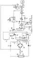
도1은 본 발명에 따른 장치의 한 실시예로서, 방전 램프가 그 장치에 접속된 의 회로 다이어그램.1 is a circuit diagram of an embodiment of an apparatus according to the present invention, in which a discharge lamp is connected to the apparatus.
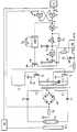
도2는 본 발명에 따른 화상 표시 장치의 한 실시예의 구성을 도시한 다이어그램.2 is a diagram showing a configuration of an embodiment of an image display apparatus according to the present invention.
본 발명의 목적은, 방전 램프를 동작시킬 수 있으면서, 특히, 광속(luminous flux)이 비교적 낮은 값을 가질 때, 비교적 낮은 정도로 광속을 적당히 변동하도록 방전 램프의 광속을 제어시킬 수 있는 회로 장치를 제공하는 것이다. 본 발명의 다른 목적은 LCD 스크린, 방전 램프와, 방전 램프를 동작시키는 회로 장치를 포함하는 화상 표시 장치를 제공하는 것으로, 심지어 휘도가 비교적 낮은 값을 가질 때 단지 비교적 낮은 정도로 적당히 휘도를 변동시키도록 LCD 스크린의 휘도가 제어될 수 있는 화상 표시 장치를 제공하는 것이다.It is an object of the present invention to provide a circuit device capable of operating a discharge lamp and controlling the luminous flux of the discharge lamp so as to appropriately vary the luminous flux to a relatively low degree when the luminous flux has a relatively low value . Another object of the present invention is to provide an image display device including an LCD screen, a discharge lamp, and a circuit device for operating a discharge lamp, wherein even when the luminance has a relatively low value, So that the brightness of the LCD screen can be controlled.
본 발명에 따라, 상기 목적을 위해, 서두에 언급된 회로 장치에 있어서, 수단(Ⅲ)에는 실질적인 방형파 변조의 각각의 사이클 동안 방전 램프의 점등을 검출하는 측정 수단과, 방전 램프의 점등 이후에 시간이 경과될 때, 고주파수 전압의 진폭을 실제로 0으로 되게 하기 위해 상기 측정 회로에 결합된 타이머가 제공되어 있는 것을 특징으로 한다.According to the invention, for this purpose, in the circuit arrangement mentioned in the opening paragraph, the means (III) comprises measuring means for detecting the lighting of the discharge lamp during each cycle of the substantial square wave modulation, Characterized in that a timer coupled to the measuring circuit is provided to make the amplitude of the high frequency voltage actually zero when the time has elapsed.
상기 두 번째 목적을 위해, 본 발명의 두 번째 서두에 기재되어 있는 화상 표시 장치에는 본 발명에 따라 회로 장치가 제공된다.For the above second object, in the image display device described in the second introduction of the present invention, a circuit device is provided according to the present invention.
상기 검출 수단은 고주파 전압의 각각의 방형파 동안 방전 램프의 점등을0. 검출한다. 방전 램프의 점등 이후에 시간이 경과했을 때, 검출 회로에 결합된 타이머 회로가 고주파 전압의 진폭을 실질적으로 0으로 하기 때문에, 방전 램프는 소등된다. 그로 인해, 방전 램프가 점등되는 동안의 시간이 각각의 방형파에서 제거되는 것이 성취된다. 점등 램프가 점등되는 동안의 시간이 제어되기 때문에, 점등 램프의 광속은 단지 낮은 정도로 적당히 변동한다. 이와 동일한 이유로 인하여, 본 발명에 따른 화상 표시 장치는 단지 작은 휘도 변동을 일으킨다.Wherein the detecting means comprises means for detecting the lighting of the discharge lamp during each square wave of the high frequency voltage. . When the time elapses after the discharge lamp is turned on, since the timer circuit coupled to the detection circuit substantially zeroes the amplitude of the high-frequency voltage, the discharge lamp is turned off. As a result, it is achieved that the time during which the discharge lamp is turned on is removed from each square wave. Since the time during which the turn-on lamp is turned on is controlled, the light beam of the turn-on lamp fluctuates only moderately to a low degree. For the same reason, the image display apparatus according to the present invention causes only small luminance fluctuation.
본 발명에 따른 회로 장치의 다른 중요한 장점은 회로 장치의 스위칭-온에 따라 방전 램프의 제 1 점등에 관계가 있다. 예를 들어, 대기 온도 또는, 방전 램프가 점등없이 어두운 환경에 있는 동안의 시간에 따라, 방전 램프의 제 1 점등은 비교적 긴 시간이 걸릴 수 있다. 공지된 회로 장치가 이용될 때, 그 회로 장치에 의해 발생된 고주파 전압은 또한 점등시에도 실질적인 방형파 형태로 변조되는데, 이는 크게 어렵게 처리될 수 있음을 의미한다. 그러나, 본 발명에 따른 회로 장치가 이용될 때, 고주파 전압은 방전 램프의 점등 동안에 실질적인 방형파형으로 변조되지 않고, 변조되지 않은 상태로 존재하기 때문에, 방전 램프는 제 1 시간 동안 비교적 빠르게 점등된다.Another important advantage of the circuit arrangement according to the invention relates to the first lighting of the discharge lamp depending on the switching-on of the circuit arrangement. For example, depending on the ambient temperature or the time while the discharge lamp is in a dark environment without lighting, the first lighting of the discharge lamp may take a relatively long time. When a known circuit device is used, the high-frequency voltage generated by the circuit device is also modulated into a substantially square wave form even upon lighting, which means that it can be processed with great difficulty. However, when the circuit device according to the present invention is used, since the high-frequency voltage is not modulated into a substantially square waveform during the lighting of the discharge lamp and exists in an unmodulated state, the discharge lamp is turned on relatively quickly during the first time.
측정 회로는 예를 들어, 광 센서에 의해 실현될 수 있다. 그러나, 그 측정 회로를 실현하는 비교적 간단하고 그에 따라 저렴한 방식은 수단(Ⅰ)에 결합된 오믹 저항기 및 다이오드 브릿지에 의해 실현된다. 그러한 커플링은 방전 램프가 점등되고, 소등 상태에서 (실질적으로) 전류가 흐르지 않을 때 오믹 저항기에 전류가 통하도록 설계될 수 있다.The measurement circuit can be realized by, for example, an optical sensor. However, a relatively simple and therefore inexpensive way of realizing the measurement circuit is realized by means of an ohmic resistor and a diode bridge coupled to Means (I). Such coupling can be designed to allow current to flow through the ohmic resistor when the discharge lamp is turned on and no (substantially) no current flows in the unlit state.
본 발명에 따른 회로 장치의 양호한 실시예에 있어서, 수단(Ⅱ)은 입력 단자와 수단(Ⅰ) 사이에 결합된 스위칭 소자를 포함한다. 본 발명에 따른 회로 장치의 양호한 실시예에 있어서, 수단(Ⅱ)은 비교적 간단하면서 신뢰성이 있는 방식으로 실현된다.In a preferred embodiment of the circuit arrangement according to the invention, the means (II) comprises a switching element coupled between the input terminal and the means (I). In a preferred embodiment of the circuit arrangement according to the invention, the means II is realized in a relatively simple and reliable manner.
본 발명에 따른 회로 장치의 다른 실시예는 각각의 방형파 동안 방전 램프가 점등되는 시간 구간의 길이를 조정하기 위한 수단을 포함한다. 이는 그들 수단을 갖는 방전 램프를 점점 흐리게 할 수 있다.Another embodiment of the circuit arrangement according to the invention comprises means for adjusting the length of the time interval during which the discharge lamp is illuminated during each square wave. This can make the discharge lamp having these means gradually blurred.
본 발명에 따른 화상 표시 장치의 양호한 실시예는 고주파 전압의 실질적인 방형파 변조의 주파수와 동일한 주파수로 LCD 스크린상의 화상을 주기적으로 생성(build-up)하기위한 수단을 포함한다. 본 발명에 따른 화상 표시 장치의 양호한 실시예에 있어서, 고주파 전압의 실질적인 방형파 변조와 LCD 스크린 상의 화상의 주기적인 생성 사이에 발생하는 간섭을 방지한다.A preferred embodiment of the image display device according to the present invention comprises means for periodically building up an image on the LCD screen at a frequency equal to the frequency of the substantially square wave modulation of the high frequency voltage. In a preferred embodiment of the image display device according to the present invention, interference between the substantial square wave modulation of the high frequency voltage and the periodic generation of the image on the LCD screen is prevented.
본 발명에 따른 회로 장치 및 화상 표시 장치의 실시예는 도면을 참조하여 설명한다.Embodiments of a circuit device and an image display device according to the present invention will be described with reference to the drawings.
도1에 있어서, K1 및 K2는 공급 전압원에 접속을 위한 입력 단자를 형성한다. 입력 단자(K2)의 전위는 램프 동작동안 접지 전위와 동일하다. 유도성 소자(L), 스위칭 소자(S1 및 S2), 변압기(T)에 1차 권선(L1, L2 및 L3)과 2차 권선(L4 및 L5) 및, 캐패시터(C2, C3 및 C4)가 제공되어, 공급 전압원에 의해 전달되는 전압으로부터 고주파 전압을 발생하기 위한 수단(Ⅰ)을 형성한다. 도1의 수단(Ⅰ)은 방전 램프(LA)에 결합되어 있다. 그 회로 장치의 모든 다른 성분은 고주파 전압의 진폭의 실질적인 방형파 변조를 위한 수단(Ⅱ)을 형성한다. 여기서, 회로부(TC)는 실질적인 방형파 변조와 동일한 주파수로 주기적인 신호를 발생하는 신호 발생기이다. 다이오드 브릿지(DB) 및 오믹 저항기(R4)는 본 실시예에 있어서, 방전 램프의 점등을 검출하는 측정 수단을 형성하고, 회로부(A, B, C 및 D), 다이오드(D2), 가변 저항기(R1 및 R2), 캐패시터(C1), 단안정(monostable) 멀티바이브레이터(MMV), 스위칭 소자(M2 및 M3) 및, 저항기(R3)는 방형파의 듀티 사이클을 조정하기 위한 수단(Ⅲ)을 형성한다. 회로부(D), 스위칭 소자(M2 및 M3) 및 저항기(R3)와 함께 다이오드(D2), 캐패시터(C1), 가변 저항기(R1 및 R2) 및, 단안정 멀티바이브레이터(MMV)는, 방전 램프의 점등 이후에 시간 구간이 경과할 때 고주파 전압의 진폭을 실질적으로 0으로 되게 하는 타이머 회로를 형성한다.In Fig. 1, K1 and K2 form an input terminal for connection to a supply voltage source. The potential of the input terminal K2 is equal to the ground potential during the lamp operation. The primary windings L1, L2 and L3 and the secondary windings L4 and L5 and the capacitors C2, C3 and C4 are connected to the inductive element L, the switching elements S1 and S2 and the transformer T, (I) for generating a high-frequency voltage from the voltage delivered by the supply voltage source. Means (I) in Fig. 1 is coupled to the discharge lamp LA. All other components of the circuit arrangement form means (II) for substantial square wave modulation of the amplitude of the high-frequency voltage. Here, the circuit portion TC is a signal generator that generates a periodic signal at the same frequency as the substantial square wave modulation. The diode bridge DB and the ohmic resistor R4 form a measuring means for detecting the lighting of the discharge lamp in this embodiment and are provided with circuit portions A, B, C and D, a diode D2, R1 and R2), the capacitor C1, the monostable multivibrator MMV, the switching elements M2 and M3 and the resistor R3 form the means III for adjusting the duty cycle of the square wave do. The diode D2, the capacitor C1, the variable resistors R1 and R2 and the monostable multivibrator MMV together with the circuit part D, the switching elements M2 and M3 and the resistor R3 are connected to the discharge lamp A timer circuit is formed which makes the amplitude of the high-frequency voltage substantially zero when the time period elapses after the lighting.
입력 단자(K1)는 스위칭 소자(M1) 및 유도성 소자(L)의 직렬 장치에 의해 1차 권선(L1 및 L2)의 공통 접합점에 접속된다. 다이오드(D1)는 스위칭 소자(M1)와 유도성 소자(L)의 공통 접합점에 입력 단자(K2)를 접속한다. 1차 권선(L1 및 L2)은 직렬로 접속되고, 캐패시터(C1)에 의해 션트된다. 1차 권선(L1 및 L2)의 직렬 장치의 제 1 단부는 스위칭 소자(S1)의 주 전극에 접속된다. 1차 권선(L1 및 L2)의 직렬 장치의 제 2 단부는 스위칭 소자(S2)의 제 1 주전극에 접속된다. 스위칭 소자(S1)의 제 2 주전극은, 스위칭 소자(2)의 제 2 주전극과 마찬가지로, 입력 단자(K2)에 접속된다. 스위칭 소자(S1)의 제어 전극은 1차 권선(L3)을 통해 스위칭 소자(S2)의 제어 전극에 접속된다. 2차 권선(L5)의 제 1 단부는 캐패시터(C3)를 통해 방전 램프(LA)의 제 1 전극에 접속된다. 2차 권선(L4)의 제 1 단부는 캐패시터(C4)를 통해 방전 램프(LA)의 제 2 전극에 접속된다. 2차 권선(L4 및 L5)의 다른 단부는 다이오드 브릿지(DB)의 각각의 입력에 접속된다. 다이오드 브릿지(DB)의 제 1 출력은 입력 단자(K2)에 접속된다. 다이오드 브릿지(DB)의 다른 출력은 저항기(R4)를 통해 입력 단자(K2)에도 접속된다. 다이오드 브릿지(DB)와 오믹 저항기(R4)의 접합점은 회로부(B)의 입력(R*)에 접속된다. 회로부(A 및 B)는NAND 게이트에 의해 각각 형성된다. 회로부(B)의 다른 입력은 회로부(A)의 한 출력에 접속된다. 회로부(B)의 한 출력은 회로부(A)의 한 입력에 접속된다. 회로부(A)의 다른 입력(S*)은 회로부(TC)의 한 출력에 접속된다. 회로부(A) 및 회로부(B)는 함께 래치를 형성한다. 그 회로부(A)의 출력은 회로부(C)의 입력에 접속되고, 인버터를 형성한다. 회로부(C)의 출력은 가변 저항기(R1) 및 캐패시터(C1)의 직렬 장치를 통해 입력 단자(K2)에 접속된다. 가변 저항기(R1)는 다이오드에 의해 션트된다. 가변 저항기(R1)와 캐패시터(C1)의 접합점은 회로부(D)의 입력에 접속되고, 또한 인버터를 형성한다. 회로부(D)의 출력은 스위칭 소자(M2)의 제어 전극에 접속된다. 스위칭 소자(M2)의 제 1 주전극은 입력 단자(K2)에 접속된다. 스위칭 소자(M2)의 다른 주전극은 저항기(R3)를 통해 단자(K1)에 접속된다. 저항기(R3)와 스위칭 소자(M2)의 접합점은 스위칭 소자(M1)의 제어 전극에 접속된다. 회로부(A)의 출력은 단안정 멀티바이브레이터(MMV)의 입력에도 접속된다. 단안정 멀티바이브레이터(MMV)는 가변 저항기(R2)를 포함한다. 단안정 멀티바이브레이터(MMV)의 출력은 스위칭 소자(M3)의 제어 전극에 결합된다. 스위칭 소자(M3)의 제 1 주전극은 입력 단자(K2)에 접속되고, 스위칭 소자(M3)의 다른 주전극은 스위칭 소자(M2)와 저항기(R3)의 접합점에 접속된다.The input terminal K1 is connected to the common junction of the primary windings L1 and L2 by the series device of the switching device M1 and the inductive element L. [ The diode D1 connects the input terminal K2 to the common junction point of the switching device M1 and the inductive element L. [ The primary windings L1 and L2 are connected in series and shunted by a capacitor C1. The first end of the series device of the primary windings L1 and L2 is connected to the main electrode of the switching device S1. The second end of the series device of the primary windings L1 and L2 is connected to the first main electrode of the switching device S2. The second main electrode of the switching element S1 is connected to the input terminal K2 like the second main electrode of the switching element 2. The control electrode of the switching element S1 is connected to the control electrode of the switching element S2 through the primary winding L3. The first end of the secondary winding L5 is connected to the first electrode of the discharge lamp LA via the capacitor C3. The first end of the secondary winding L4 is connected to the second electrode of the discharge lamp LA via the capacitor C4. The other ends of the secondary windings L4 and L5 are connected to respective inputs of the diode bridge DB. The first output of the diode bridge DB is connected to the input terminal K2. The other output of the diode bridge DB is also connected to the input terminal K2 through the resistor R4. The junction point of the diode bridge DB and the ohmic resistor R4 is connected to the input R* of the circuit part B. The circuit portions A and B are respectively formed by NAND gates. The other input of the circuit part B is connected to one output of the circuit part A. One output of the circuit part B is connected to one input of the circuit part A. The other input S* of the circuit part A is connected to one output of the circuit part TC. The circuit portion A and the circuit portion B together form a latch. The output of the circuit portion A is connected to the input of the circuit portion C to form an inverter. The output of the circuit portion C is connected to the input terminal K2 through the series device of the variable resistor R1 and the capacitor C1. The variable resistor R1 is shunted by a diode. The junction point of the variable resistor R1 and the capacitor C1 is connected to the input of the circuit portion D and forms an inverter. The output of the circuit portion D is connected to the control electrode of the switching element M2. The first main electrode of the switching element M2 is connected to the input terminal K2. The other main electrode of the switching element M2 is connected to the terminal K1 through the resistor R3. The junction of the resistor R3 and the switching element M2 is connected to the control electrode of the switching element M1. The output of the circuit portion A is also connected to the input of the monostable multivibrator (MMV). The monostable multivibrator (MMV) includes a variable resistor R2. The output of the monostable multivibrator (MMV) is coupled to the control electrode of the switching element M3. The first main electrode of the switching device M3 is connected to the input terminal K2 and the other main electrode of the switching device M3 is connected to the junction of the switching device M2 and the resistor R3.
도1에 도시된 회로 장치의 동작은 다음과 같다.The operation of the circuit device shown in Fig. 1 is as follows.
입력 단자(K1 및 K2)는 공급 전압원에 접속되고, 신호 발생기(TC)는 주파수(f)를 갖는 맥동(pulsatory) 신호를 발생한다. 상기 맥동 신호의 펄스 이후에, 회로부(A)의 출력은 하이가 된다. 결과적으로, 회로부(C)의 출력은 로우가 되기 때문에, 캐패시터(C1)는 다이오드(D2)를 통해 방전된다. 그 회로부(C)의 입력은 결과적으로 로우가 되고, 그 출력이 하이로 되기 때문에, 스위칭 소자(M1)는 스위칭 소자(M2)를 통해 전도된다. 스위칭 소자(M1)가 전도된 이후에, 결과적으로 방전 램프(LA) 양단에 고주파 전압이 존재하게 된다. 소등 상태에서의 방전 램프(LA)는 그 고주파 전압의 결과로서 실질적으로 점등된다. 상기 방전 램프(LA)의 점등은 오믹 저항기(R4)에 흐르는 전류를 검출하고, 그후, 회로부(A 및 B)에 의해 형성되는 래치의 입력(R*)에 한 신호를 공급한다. 그 래치는 상기 신호에 의해 리셋되어, 회로부(A)의 출력이 로우가 되고, 회로부(C)의 출력이 하이가 되어, 캐패시터(C1)는 가변 저항기(R1)를 통해 충전된다. 동시에, 단안정 멀티바이브레이터(MMV)의 입력은 로우로 되는데, 그 이유는 회로부(A)의 출력이 로우로 되기 때문이다. 결과적으로, 단안정 멀티바이브레이터(MMV)의 출력은 가변 저항기(R2)의 저항값에 의해 결정된 시간 구간 동안 하이로 된다. 상기 시간 구간 동안, 스위칭 소자(M3)는 전도(conducting)된다. 캐패시터(C1)의 양단 전압이 임계값에 도달할 때, 회로부(D)의 출력이 로우로 됨에 따라, 스위칭 소자(M2)는 비전도(non-conducting)된다. 스위칭 소자(M2 및 M3)의 어느 한 소자 또는 둘 모두의 소자가 전도되는 동안, 스위칭 소자(M1)도 전도된다. 두 스위칭 소자(M2 및 M3) 중 최종 한 소자가 비전도되는 순간, 스위칭 소자(M1)도 또한 비전도된다. 그로 인해, 수단(Ⅰ)은 공급 전압원으로부터 분리되기 때문에, 방전 램프(LA) 양단의 전압은 실질적으로 0과 동일하게 되고, 그 방전 램프(LA)는 소등된다. 상기 기술한 사이클은 회로부(TC)에 의해 발생된 각각의 연속된 펄스에서 반복된다.The input terminals K1 and K2 are connected to a supply voltage source and the signal generator TC generates a pulsatory signal having a frequency f. After the pulse of the pulsation signal, the output of the circuit section A becomes high. As a result, since the output of the circuit portion C becomes low, the capacitor C1 is discharged through the diode D2. The input of the circuit portion C becomes low as a result, and the output of the circuit portion C becomes high, so that the switching element M 1 is conducted through the switching element M 2. As a result, after the switching device M1 is conducted, a high-frequency voltage is present across the discharge lamp LA. The discharge lamp LA in the unlit state is substantially turned on as a result of the high-frequency voltage. The lighting of the discharge lamp LA detects the current flowing in the ohmic resistor R4 and then supplies a signal to the input R* of the latch formed by the circuit portions A and B. [ The latch is reset by the signal so that the output of the circuit part A goes low and the output of the circuit part C goes high and the capacitor C1 is charged through the variable resistor R1. At the same time, the input of the monostable multivibrator (MMV) is low, because the output of the circuit portion A is low. As a result, the output of the monostable multivibrator (MMV) goes high for a time period determined by the resistance value of the variable resistor R2. During this time interval, the switching element M3 is conducting. When the voltage across the capacitor C1 reaches the threshold value, as the output of the circuit part D goes low, the switching element M2 becomes non-conducting. The switching element Ml is also conducted while the element of either or both of the switching elements M2 and M3 is conducting. As soon as the last one of the two switching elements M2 and M3 is turned off, the switching element M1 is also not turned on. As a result, since the means I is separated from the supply voltage source, the voltage across the discharge lamp LA becomes substantially equal to zero, and the discharge lamp LA is turned off. The cycle described above is repeated for each successive pulse generated by the circuit TC.
예를 들어, 도1에 도시된 실시예의 실용적으로 구현하는 제조에 있어서, 방전 램프(LA)가 여전히 안정된 방법으로 동작하는 방형파 변조의 최저 듀티 사이클에 따라 가변 저항기(R1)의 저항값을 설정할 수 있다. 그와 같은 실용적인 구현에 있어서, 가변 저항기(R2)의 조정은 점점 흐려지게 하는 시설(dimming facility)과 같은 회로 장치의 이용자에 유용하게 될 수 있다. 사용자는 도1에 도시된 실시예의 그들 실용적인 구현들을 사용할 때 방전 램프(LA)가 더 이상 안정된 동작을 나타내지 않는 범위까지 방전 램프를 점차 흐려지게 할 수 없다. 그 이유는 가장 낮게 약하게 된 위치가 사실상 스위칭 소자(M2)의 전도 시간에 의해 결정되고, 차례로 가변 저항기(R1)의 저항값에 의해 결정되기 때문이다.For example, in a practical implementation of the embodiment shown in Fig. 1, the resistance value of the variable resistor R1 is set according to the lowest duty cycle of the square wave modulation in which the discharge lamp LA still operates in a stable manner . In such a practical implementation, adjustment of the variable resistor R2 may be useful to users of circuit devices such as dimming facilities. The user can not gradually blur the discharge lamp to such an extent that the discharge lamp LA no longer exhibits stable operation when using their practical implementations of the embodiment shown in Fig. This is because the lowest attenuated position is determined by the conduction time of the switching element M2 in effect and is determined by the resistance value of the variable resistor R1 in turn.
도2에 도시된 화상 표시 장치는 도1에 도시된 것과 같은 방전 램프에 결합된 회로 장치를 포함한다. 그 화상 표시 장치는 또한, LCD 스크린 및 회로부(BO)를 포함하고, 본 실시예에 있어서 상기 회로부는 수단(Ⅰ)에 의해 발생된 고주파 전압의 실지적인 방형파 변조의 주파수와 동일한 주파수로 LCD 스크린 상의 화상을 주기적으로 생성하기 위한 수단을 형성한다.The image display apparatus shown in Fig. 2 includes a circuit device coupled to a discharge lamp as shown in Fig. The image display device also includes an LCD screen and a circuit part BO in which the circuit part is connected to the LCD screen at the same frequency as the actual square wave modulation frequency of the high frequency voltage generated by the means I, Lt; RTI ID = 0.0 > periodically < / RTI >
회로부(TC)의 출력은 회로부(BO)의 입력에 접속되고, 회로부(BO)의 출력은 스크린(LCD)의 한 입력에 접속된다. 스크린(LCD)은 전체 LCD 스크린을 통해 광도의 양호한 분포가 얻어지도록 방전 램프(LA)에 관련되어 배치된다.The output of the circuit portion TC is connected to the input of the circuit portion BO and the output of the circuit portion BO is connected to one input of the screen LCD. The screen (LCD) is arranged in relation to the discharge lamp (LA) so as to obtain a good distribution of luminous intensity over the entire LCD screen.
도2에 도시된 화상 표시 장치의 동작은 다음과 같다.The operation of the image display apparatus shown in Fig. 2 is as follows.
화상 표시 장치의 동작동안 회로부(TC)에 의해 발생되는 각각의 펄스는 그 스크린(LCD)의 입력을 통해 스크린(LCD) 상의 화상을 변경시키는 회로부(BO)의 출력에서 한 신호의 발생을 유도한다. 또한, 회로부(TC)에 의해 발생된 각각의 펄스는 실질적인 방형파 변조의 방형파를 일으키고, 고주파 전압의 실질적인 방형파 변조와 LCD 스크린 상의 화상의 생성은 동일한 주파수를 가지며, 그로 인해, 동기화된다. 따라서, 두 개의 신호 사이에 간섭을 일으키지 않고, LCD 스크린 상에 형성된 화상은 실질적으로 양호한 대역 및/또는 라인을 갖도록 달성할 수 있다.Each pulse generated by the circuit TC during operation of the image display device induces the generation of a signal at the output of the circuit BO changing the image on the screen (LCD) through the input of its screen (LCD) . Further, each pulse generated by the circuit portion TC causes a square wave of substantial square wave modulation, and the substantial square wave modulation of the high frequency voltage and the generation of the image on the LCD screen have the same frequency and are therefore synchronized. Thus, without causing interference between the two signals, the image formed on the LCD screen can be achieved to have a substantially better band and / or line.
Claims (6)
Translated fromKoreanApplications Claiming Priority (3)
| Application Number | Priority Date | Filing Date | Title |
|---|---|---|---|
| EP95201880,2 | 1995-07-10 | ||
| EP95201880 | 1995-07-10 | ||
| EP95201880.2 | 1995-07-10 |
Publications (2)
| Publication Number | Publication Date |
|---|---|
| KR970705919A KR970705919A (en) | 1997-10-09 |
| KR100420233B1true KR100420233B1 (en) | 2004-06-24 |
Family
ID=8220466
Family Applications (1)
| Application Number | Title | Priority Date | Filing Date |
|---|---|---|---|
| KR1019970701471AExpired - Fee RelatedKR100420233B1 (en) | 1995-07-10 | 1996-06-21 | Circuit device |
Country Status (6)
| Country | Link |
|---|---|
| US (1) | US5841246A (en) |
| EP (1) | EP0781500B1 (en) |
| JP (1) | JP3905923B2 (en) |
| KR (1) | KR100420233B1 (en) |
| DE (1) | DE69617616T2 (en) |
| WO (1) | WO1997003541A1 (en) |
Families Citing this family (11)
| Publication number | Priority date | Publication date | Assignee | Title |
|---|---|---|---|---|
| DE19733939A1 (en)* | 1997-08-06 | 1999-02-11 | Mannesmann Vdo Ag | Fluorescent lamp dimming circuit |
| DE19717307C1 (en)* | 1997-04-24 | 1998-07-30 | Mannesmann Vdo Ag | Method of dimming fluorescent lamp in secondary circuit of transformer |
| EP0978221B1 (en) | 1997-04-24 | 2004-12-22 | Siemens Aktiengesellschaft | Circuitry for dimming a fluorescent lamp |
| US6118221A (en)* | 1997-10-16 | 2000-09-12 | Tokin Corporation | Cold-cathode tube lighting circuit with protection circuit for piezoelectric transformer |
| US6160360A (en)* | 1998-12-28 | 2000-12-12 | The Amcor Group, Ltd. | Power control with reduced radio frequency interference |
| US6252355B1 (en)* | 1998-12-31 | 2001-06-26 | Honeywell International Inc. | Methods and apparatus for controlling the intensity and/or efficiency of a fluorescent lamp |
| DE19938401A1 (en)* | 1999-08-13 | 2001-03-08 | Bosch Gmbh Robert | Method for controlling a cold cathode discharge light source and device |
| DE10021537A1 (en)* | 2000-05-03 | 2001-11-08 | Philips Corp Intellectual Pty | Method and device for operating a gas discharge lamp |
| US6570347B2 (en) | 2000-06-01 | 2003-05-27 | Everbrite, Inc. | Gas-discharge lamp having brightness control |
| US10057964B2 (en) | 2015-07-02 | 2018-08-21 | Hayward Industries, Inc. | Lighting system for an environment and a control module for use therein |
| US10957445B2 (en) | 2017-10-05 | 2021-03-23 | Hill-Rom Services, Inc. | Caregiver and staff information system |
Citations (6)
| Publication number | Priority date | Publication date | Assignee | Title |
|---|---|---|---|---|
| US4682083A (en)* | 1984-10-29 | 1987-07-21 | General Electric Company | Fluorescent lamp dimming adaptor kit |
| KR880004721A (en)* | 1986-09-11 | 1988-06-07 | 이용식 | Lighting device for electronic discharge lamp |
| US4766350A (en)* | 1981-09-11 | 1988-08-23 | U.S. Philips Corporation | Electric circuit with transient voltage doubling for improved operation of a discharge lamp |
| US5001386A (en)* | 1989-12-22 | 1991-03-19 | Lutron Electronics Co., Inc. | Circuit for dimming gas discharge lamps without introducing striations |
| US5105127A (en)* | 1989-06-30 | 1992-04-14 | Thomson-Csf | Dimming method and device for fluorescent lamps used for backlighting of liquid crystal screens |
| KR940017963A (en)* | 1992-12-16 | 1994-07-27 | 프레데릭 얀 스미트 | Circuit device for high frequency operation of discharge lamp |
Family Cites Families (4)
| Publication number | Priority date | Publication date | Assignee | Title |
|---|---|---|---|---|
| GB2244608A (en)* | 1990-04-23 | 1991-12-04 | P I Electronics Pte Ltd | High frequency drive circuit for a fluorescent lamp |
| DE69106890T2 (en)* | 1990-12-03 | 1995-06-08 | Allied Signal Inc | CONTROL CIRCUIT WITH A WIDE ADJUSTMENT RANGE FOR A GAS DISCHARGE LAMP. |
| US5243261A (en)* | 1991-02-07 | 1993-09-07 | U.S. Philips Corporation | Modulated high frequency dimmer circuit with infrared suppression |
| NL9100459A (en)* | 1991-03-15 | 1992-10-01 | Philips Nv | SWITCHING DEVICE. |
- 1996
- 1996-06-21DEDE69617616Tpatent/DE69617616T2/ennot_activeExpired - Fee Related
- 1996-06-21WOPCT/IB1996/000600patent/WO1997003541A1/enactiveIP Right Grant
- 1996-06-21EPEP96916271Apatent/EP0781500B1/ennot_activeExpired - Lifetime
- 1996-06-21JPJP50562997Apatent/JP3905923B2/ennot_activeExpired - Fee Related
- 1996-06-21KRKR1019970701471Apatent/KR100420233B1/ennot_activeExpired - Fee Related
- 1996-07-09USUS08/677,241patent/US5841246A/ennot_activeExpired - Fee Related
Patent Citations (7)
| Publication number | Priority date | Publication date | Assignee | Title |
|---|---|---|---|---|
| US4766350A (en)* | 1981-09-11 | 1988-08-23 | U.S. Philips Corporation | Electric circuit with transient voltage doubling for improved operation of a discharge lamp |
| US4682083A (en)* | 1984-10-29 | 1987-07-21 | General Electric Company | Fluorescent lamp dimming adaptor kit |
| KR880004721A (en)* | 1986-09-11 | 1988-06-07 | 이용식 | Lighting device for electronic discharge lamp |
| US5105127A (en)* | 1989-06-30 | 1992-04-14 | Thomson-Csf | Dimming method and device for fluorescent lamps used for backlighting of liquid crystal screens |
| US5001386A (en)* | 1989-12-22 | 1991-03-19 | Lutron Electronics Co., Inc. | Circuit for dimming gas discharge lamps without introducing striations |
| US5001386B1 (en)* | 1989-12-22 | 1996-10-15 | Lutron Electronics Co | Circuit for dimming gas discharge lamps without introducing striations |
| KR940017963A (en)* | 1992-12-16 | 1994-07-27 | 프레데릭 얀 스미트 | Circuit device for high frequency operation of discharge lamp |
Also Published As
| Publication number | Publication date |
|---|---|
| WO1997003541A1 (en) | 1997-01-30 |
| DE69617616D1 (en) | 2002-01-17 |
| JPH10505943A (en) | 1998-06-09 |
| DE69617616T2 (en) | 2002-08-14 |
| EP0781500B1 (en) | 2001-12-05 |
| JP3905923B2 (en) | 2007-04-18 |
| KR970705919A (en) | 1997-10-09 |
| US5841246A (en) | 1998-11-24 |
| EP0781500A1 (en) | 1997-07-02 |
Similar Documents
| Publication | Publication Date | Title |
|---|---|---|
| US5811940A (en) | Phase-shift lamp control | |
| KR100271749B1 (en) | Driver of cold-cathode fluorecent lamp | |
| US6469922B2 (en) | Method and apparatus for controlling minimum brightness of a flourescent lamp | |
| US5105127A (en) | Dimming method and device for fluorescent lamps used for backlighting of liquid crystal screens | |
| US6051935A (en) | Circuit arrangement for controlling luminous flux produced by a light source | |
| KR100420233B1 (en) | Circuit device | |
| ATE164285T1 (en) | DIMMABLE BALLAST WITH CURRENT MEASUREMENT | |
| EP0266207A2 (en) | Devices and methods of controlling alternating electric current | |
| EP0053896A1 (en) | Light dimmer device | |
| KR100704357B1 (en) | Discharge lamp luminaire | |
| US4988924A (en) | Circuit arrangement for controlling the brightness of a lamp | |
| KR19980701542A (en) | PROCESS AND CIRCUIT ARRANGEMENT FOR OPERATING COLD CATHO DE DISCHARGE LAMPS | |
| US5424616A (en) | Modulatged high frequency discharge lamp operating circuit with IR suppression | |
| EP0648067B1 (en) | Starter for inductive and capacitive ballasts | |
| ATE318068T1 (en) | INVERTER FOR SUPPLYING A DISCHARGE LAMP WITH A SURPRISELY VARIABLE FREQUENCY | |
| GB2023898A (en) | Frequency sensitive switching circuit | |
| KR930007935Y1 (en) | Dimming Control Electronic Ballast Circuit | |
| EP0860097B1 (en) | Circuit arrangement | |
| KR20010041876A (en) | Circuit arrangement | |
| KR200206209Y1 (en) | Wall mounted electronic switch means for lighting lamps | |
| ATE200842T1 (en) | METHOD FOR SWITCHING OFF A CIRCUIT ARRANGEMENT FOR OPERATING A DISCHARGE LAMP | |
| JP3399024B2 (en) | Discharge lamp lighting device for continuous dimming | |
| KR940002676Y1 (en) | Stabilizer circuit for electronic method fluorescent can dimming control | |
| JP2617482B2 (en) | Discharge lamp lighting device | |
| JP3760521B2 (en) | Light control device |
Legal Events
| Date | Code | Title | Description |
|---|---|---|---|
| PA0105 | International application | St.27 status event code:A-0-1-A10-A15-nap-PA0105 | |
| R17-X000 | Change to representative recorded | St.27 status event code:A-3-3-R10-R17-oth-X000 | |
| PG1501 | Laying open of application | St.27 status event code:A-1-1-Q10-Q12-nap-PG1501 | |
| R17-X000 | Change to representative recorded | St.27 status event code:A-3-3-R10-R17-oth-X000 | |
| N231 | Notification of change of applicant | ||
| PN2301 | Change of applicant | St.27 status event code:A-3-3-R10-R13-asn-PN2301 St.27 status event code:A-3-3-R10-R11-asn-PN2301 | |
| R17-X000 | Change to representative recorded | St.27 status event code:A-3-3-R10-R17-oth-X000 | |
| A201 | Request for examination | ||
| P11-X000 | Amendment of application requested | St.27 status event code:A-2-2-P10-P11-nap-X000 | |
| P13-X000 | Application amended | St.27 status event code:A-2-2-P10-P13-nap-X000 | |
| PA0201 | Request for examination | St.27 status event code:A-1-2-D10-D11-exm-PA0201 | |
| D13-X000 | Search requested | St.27 status event code:A-1-2-D10-D13-srh-X000 | |
| D14-X000 | Search report completed | St.27 status event code:A-1-2-D10-D14-srh-X000 | |
| E701 | Decision to grant or registration of patent right | ||
| PE0701 | Decision of registration | St.27 status event code:A-1-2-D10-D22-exm-PE0701 | |
| GRNT | Written decision to grant | ||
| PR0701 | Registration of establishment | St.27 status event code:A-2-4-F10-F11-exm-PR0701 | |
| PR1002 | Payment of registration fee | St.27 status event code:A-2-2-U10-U12-oth-PR1002 Fee payment year number:1 | |
| PG1601 | Publication of registration | St.27 status event code:A-4-4-Q10-Q13-nap-PG1601 | |
| FPAY | Annual fee payment | Payment date:20070126 Year of fee payment:4 | |
| PR1001 | Payment of annual fee | St.27 status event code:A-4-4-U10-U11-oth-PR1001 Fee payment year number:4 | |
| LAPS | Lapse due to unpaid annual fee | ||
| PC1903 | Unpaid annual fee | St.27 status event code:A-4-4-U10-U13-oth-PC1903 Not in force date:20080214 Payment event data comment text:Termination Category : DEFAULT_OF_REGISTRATION_FEE | |
| P22-X000 | Classification modified | St.27 status event code:A-4-4-P10-P22-nap-X000 | |
| PC1903 | Unpaid annual fee | St.27 status event code:N-4-6-H10-H13-oth-PC1903 Ip right cessation event data comment text:Termination Category : DEFAULT_OF_REGISTRATION_FEE Not in force date:20080214 | |
| R18-X000 | Changes to party contact information recorded | St.27 status event code:A-5-5-R10-R18-oth-X000 | |
| PN2301 | Change of applicant | St.27 status event code:A-5-5-R10-R13-asn-PN2301 St.27 status event code:A-5-5-R10-R11-asn-PN2301 | |
| R18-X000 | Changes to party contact information recorded | St.27 status event code:A-5-5-R10-R18-oth-X000 | |
| R18-X000 | Changes to party contact information recorded | St.27 status event code:A-5-5-R10-R18-oth-X000 | |
| R18-X000 | Changes to party contact information recorded | St.27 status event code:A-5-5-R10-R18-oth-X000 |