KR100413807B1 - Parallel 6-axis force-moment measuring device - Google Patents
Parallel 6-axis force-moment measuring deviceDownload PDFInfo
- Publication number
- KR100413807B1 KR100413807B1KR1019970004755AKR19970004755AKR100413807B1KR 100413807 B1KR100413807 B1KR 100413807B1KR 1019970004755 AKR1019970004755 AKR 1019970004755AKR 19970004755 AKR19970004755 AKR 19970004755AKR 100413807 B1KR100413807 B1KR 100413807B1
- Authority
- KR
- South Korea
- Prior art keywords
- force
- parallel
- support plate
- signal
- axis
- Prior art date
- Legal status (The legal status is an assumption and is not a legal conclusion. Google has not performed a legal analysis and makes no representation as to the accuracy of the status listed.)
- Expired - Lifetime
Links
Images


Classifications
- G—PHYSICS
- G01—MEASURING; TESTING
- G01L—MEASURING FORCE, STRESS, TORQUE, WORK, MECHANICAL POWER, MECHANICAL EFFICIENCY, OR FLUID PRESSURE
- G01L5/00—Apparatus for, or methods of, measuring force, work, mechanical power, or torque, specially adapted for specific purposes
- G01L5/16—Apparatus for, or methods of, measuring force, work, mechanical power, or torque, specially adapted for specific purposes for measuring several components of force
- G01L5/161—Apparatus for, or methods of, measuring force, work, mechanical power, or torque, specially adapted for specific purposes for measuring several components of force using variations in ohmic resistance
- G01L5/162—Apparatus for, or methods of, measuring force, work, mechanical power, or torque, specially adapted for specific purposes for measuring several components of force using variations in ohmic resistance of piezoresistors
- G—PHYSICS
- G01—MEASURING; TESTING
- G01L—MEASURING FORCE, STRESS, TORQUE, WORK, MECHANICAL POWER, MECHANICAL EFFICIENCY, OR FLUID PRESSURE
- G01L1/00—Measuring force or stress, in general
- G01L1/20—Measuring force or stress, in general by measuring variations in ohmic resistance of solid materials or of electrically-conductive fluids; by making use of electrokinetic cells, i.e. liquid-containing cells wherein an electrical potential is produced or varied upon the application of stress
- G01L1/22—Measuring force or stress, in general by measuring variations in ohmic resistance of solid materials or of electrically-conductive fluids; by making use of electrokinetic cells, i.e. liquid-containing cells wherein an electrical potential is produced or varied upon the application of stress using resistance strain gauges
- G—PHYSICS
- G01—MEASURING; TESTING
- G01L—MEASURING FORCE, STRESS, TORQUE, WORK, MECHANICAL POWER, MECHANICAL EFFICIENCY, OR FLUID PRESSURE
- G01L1/00—Measuring force or stress, in general
- G01L1/26—Auxiliary measures taken, or devices used, in connection with the measurement of force, e.g. for preventing influence of transverse components of force, for preventing overload
- G—PHYSICS
- G01—MEASURING; TESTING
- G01L—MEASURING FORCE, STRESS, TORQUE, WORK, MECHANICAL POWER, MECHANICAL EFFICIENCY, OR FLUID PRESSURE
- G01L5/00—Apparatus for, or methods of, measuring force, work, mechanical power, or torque, specially adapted for specific purposes
- G01L5/16—Apparatus for, or methods of, measuring force, work, mechanical power, or torque, specially adapted for specific purposes for measuring several components of force
- G01L5/161—Apparatus for, or methods of, measuring force, work, mechanical power, or torque, specially adapted for specific purposes for measuring several components of force using variations in ohmic resistance
- G01L5/1623—Apparatus for, or methods of, measuring force, work, mechanical power, or torque, specially adapted for specific purposes for measuring several components of force using variations in ohmic resistance of pressure sensitive conductors
Landscapes
- Physics & Mathematics (AREA)
- General Physics & Mathematics (AREA)
- Force Measurement Appropriate To Specific Purposes (AREA)
Abstract
Translated fromKoreanDescription
Translated fromKorean본 발명은 공간상의 임의의 구조물에 작용하는 힘과 모멘트를 측정하기 위한 힘-모멘트 측정장치에 관한 것으로서, 특히 6자유도 병렬기구의 고유한 특성을 이용하여 공간상의 구조물에 작용하는 임의의 힘과 모멘트를 그 크기는 물론 방향까지 정확하게 측정할 수 있는 병렬형 6축 힘-모멘트 측정장치에 관한 것이다.The present invention relates to a force-moment measuring device for measuring the force and moment acting on any structure in space, and in particular, by using the unique characteristics of the six degree of freedom parallel mechanism The present invention relates to a parallel six-axis force-moment measuring device capable of measuring moments accurately in both directions and directions.
병렬 기구는 첨단부와 베이스가 2개 이상의 직렬관절에 의해 폐루프(closed -loop)를 형성하며 서로의 운동을 구속하는 형대로 이루어져 있으므로, 첨단부에 작용하는 하중이 각 조인트에 분산되어 안정된 큰 힘을 지지할 수 있는 구조를 가진다.The parallel mechanism consists of a shape in which the tip and the base form a closed-loop by two or more series joints and restrain each other's motion, so that the load acting on the tip is distributed to each joint and stable. It has a structure that can support force.
도 1은 그와 같은 구조를 가진 종래의 6축 힘-모멘트 측정장치의 개략적인 구성도이다.1 is a schematic configuration diagram of a conventional six-axis force-moment measuring device having such a structure.
도 1을 참조하면, 종래 6축 힘-모멘트 측정장치는 중심부에 위치한 허브(11)를 중심으로 3개의 감지부(12)와 3개의 과부하 보호봉(13)이 상호 교번으로 60°간격으로 방사상으로 마련되어 있고, 상기 감지부(12)와 과부하 보호봉(13)의 외측에는 각 감지부(12)와 과부하 보호봉(13)의 단부를 연결하는 원통형의 보호부재(14)가 에워 싸여 있다. 참조 부호 12s는 각 감지부(12)에 복수개씩 마련되어 있는 스트레인 게이지(strain gauge)를 나타낸다.Referring to FIG. 1, in the conventional six-axis force-moment measuring device, three
그런데, 이상과 같은 구조를 가지는 종래 6축 힘-모멘트 측정장치는 그 구조상 가공작업이 어렵고, 특히 감지부(12)의 가공오차로 인한 측정장치 간의 상호 간섭으로 출력저하 및 비직선성이 유발되며, 일측 방향의 힘-모멘트가 작용될 시 타측 방향의 출력을 발생시키는 단점이 있다. 또한, 장치의 일부분이 파손되었을 시 부분적인 보수가 불가능하고, 대용량 고하중 측정이 어려우며, 대용량의 측정장치 제작 시 장치가 거대해지는 문제점이 있다.However, the conventional six-axis force-moment measuring device having the structure as described above is difficult in the machining operation, and in particular, output reduction and non-linearity is caused by mutual interference between the measuring devices due to the machining error of the
본 발명은 상기와 같은 문제점을 감안하여 창출된 것으로서, 제작이 용이하고 상호 간섭이 없으며, 부분적인 유지보수가 가능하고 대용량 고하중의 측정이 가능한 병렬형 6축 힘-모멘트 측정장치를 제공함에 그 목적이 있다.The present invention has been made in view of the above problems, and provides a parallel 6-axis force-moment measuring device that is easy to manufacture, free from mutual interference, partial maintenance, and large capacity and high load measurement. There is a purpose.
도 1은 종래의 6축 힘-모멘트 측정장치의 개략적인 구성도.1 is a schematic configuration diagram of a conventional six-axis force-moment measuring device.
도 2는 본 발명에 따른 병렬형 6축 힘-모멘트 측정장치의 전체적인 시스템을 개략적으로 나타내 보인 블록구성도.Figure 2 is a block diagram schematically showing the overall system of the parallel six-axis force-moment measuring apparatus according to the present invention.
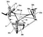
도 3은 본 발명에 따른 병렬형 6축 힘-모멘트 측정장치의 기계적 구조부의 장치구성도.Figure 3 is a device configuration of the mechanical structure of the parallel six-axis force-moment measuring device according to the present invention.
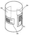
도 4는 본 발명에 따른 병렬형 6축 힘-모멘트 측정장치에 있어서, 감지부의 스트레인 게이지의 설치 상태도.Figure 4 is an installation state of the strain gage of the sensing unit in the parallel six-axis force-moment measurement apparatus according to the present invention.
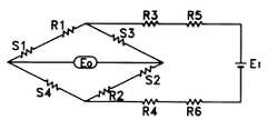
도 5는 본 발명에 따른 병렬형 6축 힘-모멘트 측정장치에 있어서, 감지부의 스트레인 게이지의 휘스톤 브리지 회로구성도.5 is a configuration of a Wheatstone bridge circuit of the strain gage of the sensing unit in the parallel six-axis force-moment measuring apparatus according to the present invention.
<도면의 주요 부분에 대한 부호의 설명><Description of the code | symbol about the principal part of drawing>
11...허브 12,22...감지부11.Herbs 12,22 ... Detection
12s,S1∼S4...스트레인 게이지 13...과부하 보호봉12s, S1 to S4 ...
14...보호부재 21...기계적 구조부14 ...
23...신호 증폭부 24...신호 변환부23.
25...연산부 26...출력부25.Calculation section 26.Output section
31...하부 지지판 32a∼32c...수직 부재
33a∼33c...수평 부재 34...상부 지지판33a to 33c ...
35...중심 축부재 36a∼36c...연결 부재35
상기의 목적을 달성하기 위하여 본 발명에 따른 병렬형 6축 힘-모멘트 측정장치는, 기계적 구조체를 형성하는 기계적 구조부와; 상기 기계적 구조부의 소정 부위에 설치되며, 각 축에 작용하는 인장력 및 압축력을 측정하기 위한 감지부와; 상기 감지부로부터의 입력 신호를 증폭하기 위한 신호 증폭부와; 상기 신호 증폭부로부터의 입력신호를 변환하기 위한 신호 변환부와; 상기 신호 변환부를 거쳐 입력된 신호를 바탕으로 임의의 공간 구조물에 작용하는 힘과 모멘트를 연산하기 위한 연산부; 및 상기 연산부의 결과를 출력하기 위한 출력부를 포함하는 점에 그 특징이 있다.In order to achieve the above object, a parallel six-axis force-moment measuring apparatus according to the present invention includes a mechanical structure forming a mechanical structure; A sensing unit installed at a predetermined portion of the mechanical structure unit and measuring a tensile force and a compressive force acting on each axis; A signal amplifier for amplifying the input signal from the detector; A signal converter for converting an input signal from the signal amplifier; A calculator for calculating a force and a moment acting on an arbitrary spatial structure based on a signal input through the signal converter; And an output unit for outputting a result of the operation unit.
이와 같은 본 발명에 의하면, 각 축부의 가공이 별도의 공정으로 이루어져 가공이 용이하고, 하중 분산능력이 큰 병렬형 구조로 되어 있어 경량화 및 대용량의 장치 제작이 가능하며, 유지/보수에 있어서 각 축부의 점검이 용이하고 보수 시 하나의 축부만을 교체할 수 있는 장점이 있다.According to the present invention, the processing of each shaft portion is a separate process is easy to process, and the parallel structure with a large load dissipation capacity is possible to reduce the weight and production of large-capacity device, each shaft portion in maintenance and repair It is easy to check, and there is an advantage that only one shaft can be replaced during repair.
이하 첨부된 도면을 참조하면서 본 발명의 실시예를 상세히 설명한다.Hereinafter, exemplary embodiments of the present invention will be described in detail with reference to the accompanying drawings.
도 2 및 도 3은 본 발명에 따른 병렬형 6축 힘-모멘트 측정장치를 나타내 보인 것으로서, 도 2는 전체적인 시스템의 개략적인 블록구성도이고, 도 3은 도 2에서 기계적 구조부의 장치구성도이다.2 and 3 show a parallel six-axis force-moment measuring device according to the present invention, Figure 2 is a schematic block diagram of the overall system, Figure 3 is a schematic diagram of the mechanical structure of Figure 2 .
도 2를 참조하면, 본 발명에 따른 병렬형 6축 힘-모멘트 측정장치는 도 3에 도시된 바와 같은 기계적 구조체를 형성하는 기계적 구조부(21)와, 그 기계적 구조부(21)의 수직 부재(32a)(32b)(32c) 및 수평 부재(33a)(33b)(33c)의 소정 부위에 설치되며, 각 축(수직 부재 및 수평 부재)에 작용하는 인장력 및 압축력을 측정하기 위한 감지부(22)와, 감지부(22)로부터의 입력 신호를 증폭하기 위한 신호 증폭부(23)와, 신호 증폭부(23)로부터의 입력신호를 변환하기 위한 신호 변환부(24)와, 신호 변환부(24)를 거쳐 입력된 신호를 바탕으로 임의의 공간 구조물에 작용하는 힘과 모멘트를 연산하기 위한 연산부(25) 및 그 연산부(25)의 결과를 출력하기 위한 출력부(26)를 구비한다.Referring to FIG. 2, the parallel six-axis force-moment measuring device according to the present invention includes a
여기서, 상기 기계적 구조부(21)는 도 3에 도시된 바와 같이 구조체를 전체적으로 지지하는 삼각형 형태의 하부 지지판(31)과, 그 하부 지지판(31)의 각 모서리 부위에 상호 소정 거리 이격되어 수직으로 고정되는 3개의 수직부재(32a)(32b)(32c)와, 3개의 수직 부재(32a)(32b)(32c)의 중심부를 향한 내측면부에 각각 수직으로 결합되는 3개의 수평 부재(33a)(33b)(33c)와, 상기 하부 지지판(31)의 상부에 소정 거리 이격되어 하부 지지판(31)과 평행하게 마련되며, 임의의 구조물을 지지하기 위한 상부 지지판(34)과, 그 상부 지지판(34)의 하부에 마련되며 상부 지지판(34)을 지지하기 위한 중심 축부재(35) 및 그 중심 축부재(35)와 상기 3개의 수평 부재(33a)(33b)(33c)를 각각 연결하기 위한 3개의 연결 부재(36a)(36b)(36c)로 구성된다. 특히, 상기 중심 축부재(35)는 상호 120°간격으로 방사상으로 뻗은 3개의 가지의 각 일측 단부가 결합된 일체형 구조를 가진다.Here, the
또한, 상기 감지부(22)에는 도 4에 도시된 바와 같이 4개의 박막식 또는 반도체 저항식 스트레인 게이지(S1∼S4)가 90°간격으로 축방향과 원주방향으로 교대로 마련되며, 도 5에 도시된 바와 같이 휘스톤 브리지(Wheatstone bridge) 회로를 구성한다. 그리고, 상기 신호 변환부(24)는 아날로그 신호를 디지탈 신호로 변환시키는 A/D(analog-to-digital) 컨버터로 구성되고, 상기 연산부(25)는 입력신호중의 힘에 소정의 이득을 곱하고, 기구의 야코비안(Jacobian) 행렬을 수행하며 그로부터 공간 구조물에 작용하는 힘/모멘트를 연산하는 것으로서 마이크로프로세서(microprocessor)가 사용되며, 상기 출력부(26)로는 디지탈 인디케이터가 사용된다.In addition, as illustrated in FIG. 4, the
그러면, 이상과 같은 구성을 가지는 본 발명의 병렬형 6축 힘-모멘트 측정장치의 동작에 대해 설명해 보기로 한다.Then, the operation of the parallel six-axis force-moment measurement apparatus of the present invention having the configuration as described above will be described.
상기 하부 지지판(31)이 임의의 구조물에 고정된 상태에서 상부 지지판(34)에 측정하고자 하는 임의의 힘(Fx,Fy,Fz)과 모멘트(Mx,My,Mz)가 가해지면, 구조물에는 이 힘(Fx,Fy,Fz)과 모멘트(Mx,My,Mz)의 반력이 발생하며 이 분력들이 각 축에 분산된다. 여기서, 각 분력들은 수평 부재(33a)(33b)(33c) 및 수직 부재(32a)(32b)(32c)들의 작용에 의해 오직 축방향의 인장력과 압축력만이 작용하게 되며, 휨력이나 비틀림력은 작용되지 않는다.When the
한편, 감지부(22)는 순수한 축방향의 인장력 및 압축력만을 받는 구조로서 상기 수평 부재(33a)(33b)(33c) 및 수직 부재(32a)(32b)(32c)에 작용하는 힘은 굽힘 모멘트와 비틀림 모멘트 및 전단력이 작용하지 않는 순수한 인장력 및 압축력이므로 박막식 또는 반도체 저항식 스트레인 게이지를 이용하여 측정이 가능하다. 각 축의 스트레인 게이지가 부착된 감지부는 외력에 의해 탄성한도 내에서 미소변형을 한다. 이 변형을 저항식 스트레인 게이지의 저항 변화로 변환하고, 감지부의 변형을 검출하여 궁극적으로 축력을 측정한다. 이에 대해 부연해 보기로 한다. 특정 축의 감지부(22)에 축력이 작용하면, 축은 미소한 탄성변형을 일으키는데, 그응력 σ와 변형률 ε과의 관계를 수식으로 표현하면 다음과 같다.On the other hand, the
[수학식 1][Equation 1]
σ= E·εσ = E
여기서,E는 영(Young)의 탄성계수를 나타낸다.Here,E represents the Young's modulus of elasticity.
따라서, 응력과 변형률의 정의에 의해서 상기 수학식 1은 다음과 같이 변형될 수 있다.Therefore, Equation 1 may be modified as follows by definition of stress and strain.
[수학식 2][Equation 2]

여기서,
한편, 도 4에서와 같이 축방향 및 원주방향으로 교대로 마련된 4개의 박막식 또는 반도체 저항식 스트레인 게이지(S1∼S4)는 감지부(22)의 변형에 따라 함께 변형을 하며, 저항체의 저항값은 스트레인 게이지(S1∼S4)의 길이에 비례한다.Meanwhile, as shown in FIG. 4, the four thin film type or semiconductor resistance strain gauges S1 to S4 alternately provided in the axial direction and the circumferential direction are deformed together according to the deformation of the
본래, 저항식 스트레인 게이지의 저항R은,Originally, the resistanceR of a resistance strain gauge is
[수학식 3][Equation 3]

로 표현된다. 여기서,

[수학식 4][Equation 4]

상기 수학식 4를 수학식 3으로 나누면, 다음과 같이 된다.
[수학식 5][Equation 5]

통상 저항식 스트레인 게이지의 변형률

[수학식 6][Equation 6]

이 때, 상기 게이지 팩터G는 박막식의 경우 2.0∼4.0이고, 반도체식의 경우는 50∼175정도의 값을 갖는다. 결과적으로, 게이지 팩터G가 높으면 낮은 스트레인에서도 저항변화에 민감하여 강도가 더 높은 피부착재를 사용할 수 있으며, 측정부의 피로수명의 연장을 가능하게 한다.At this time, the gauge factorG is 2.0 to 4.0 in the case of a thin film type, and has a value of about 50 to 175 in the case of a semiconductor type. As a result, the higher gauge factorG is sensitive to resistance changes, even at low strains, allowing the use of higher-strength skin coatings and the extension of the fatigue life of the measuring section.
또한, 상기 수학식 5 및 수학식 6으로부터 다음과 같은 수식을 유도할 수 있다.In addition, the following equations may be derived from Equations 5 and 6.
[수학식 7][Equation 7]

상기 수학식 7에서,G,A,E는 물성치로서 알려진 값이며, 따라서 측정하려는 힘
한편, 도 5에서 S1∼S4는 저항식 스트레인 게이지, R1은 영점조정용 저항,R2는 온도변화에 따른 영점변화보상용 저항, R3, R4,는 온도변화에 따른 출력보상용 저항, E0는 저항변화에 따른 출력전압, Ei는 입력전압이라 할 때, 출력전압과 입력전압 사이에는 다음과 같은 관계가 성립한다.Meanwhile, in FIG. 5, S1 to S4 are resistance strain gauges, R1 is a zero adjustment resistor, R2 is a zero point compensation resistor according to temperature change, R3 and R4 are output compensation resistors according to temperature change, E0 is a resistance change When the output voltage and Ei are the input voltages, the following relationship is established between the output voltage and the input voltage.
[수학식 8][Equation 8]

여기서, v는 프와송 계수로서 0.3의 값을 갖는다. 이 식을 다시 정리하면 다음과 같다.Where v has a value of 0.3 as the Poisson coefficient. If we rearrange this equation,
[수학식 9][Equation 9]

따라서, 감지부(22)에 작용하는 힘
여기서, 이와 같은 축력 측정결과로부터 본 발명의 측정장치의 상부 지지판(34)에 작용하는 6자유도 힘/모멘트를 구하기 위해서는 다음의 가정이 필요하다.Here, the following assumption is necessary to obtain the six degrees of freedom force / moment acting on the
첫째, 축 이외의 하부 지지판(31)과 상부 지지판(34)의 구면축수는 강체이며 축의 작용력에 의한 미소 인장 및 압축 변위는 무시할 만큼 작아서 외력 작용 시 6축 측정장치 기구부의 전체 형태는 불변한다.First, the spherical shaft numbers of the
둘째, 각 접속부에는 마찰력이 작용하지 않으며, 따라서 축에는 휨력이나 비틀림력이 없고 순수한 축방향의 인장력 및 압축력만이 작용한다.Secondly, no frictional force acts on each connection, so there is no bending or torsional force on the shaft, and only purely axial tensile and compressive forces act.
이상과 같은 가정하에서 본 발명의 측정장치에 의한 6자유도 힘/모멘트 측정원리에 대해 설명해 보기로 한다.Under the above assumptions, the six degree of freedom force / moment measurement principle by the measuring device of the present invention will be described.
본 발명의 측정장치의 기구부의 링크와 조인트의 조합을 고려한 기구학 해석을 기초로 하여 미분 기구학을 해석하면, 기구부의 구조적 특성을 내포한 야코비안Jik를 구할 수 있다. 이러한 병렬기구의 야코비안의 특성으로부터 축방향의 힘에 의한 각 축의 미소 탄성변위를
[수학식 10][Equation 10]

또한, 감지부가 부착된 각 축(수직 부재 및 수평 부재)에 작용하는 힘을 라

[수학식 11][Equation 11]

그리고, 상기 수학식 10을 다시 정리하면 다음과 같다.Then, the equation (10) is rearranged as follows.
[수학식 12][Equation 12]

상기 수학식 11로부터, 다음의 결과를 얻는다.From the above equation (11), the following results are obtained.
[수학식 13][Equation 13]

그리고, 수학식 12의 결과에 의해 최종적으로 6자유도 힘/모멘트는 다음과 같은 행렬식으로 표시될 수 있다.Finally, the six degrees of freedom force / moment may be expressed by the following determinant as a result of
[수학식 14][Equation 14]

따라서, 상기 수학식 13에 의해 최종적으로 측정하고자 하는 임의의 힘(Fx,Fy,Fz)과 모멘트(Mx,My,Mz)가 구해진다. 이와 같이, 기구부의 상부 지지판에 작용하는 힘과 모멘트를 직접 측정하는 대신 축에 작용하는 저항 변화에 따른 출력전압을 측정하고 야코비안 행렬을 곱하여 줌으로써 임의의 구조물에 작용하는 힘과 모멘트를 측정할 수 있는 것이다.Therefore, the arbitrary forces (Fx, Fy, Fz) and moments (Mx, My, Mz) to be finally measured by
이상의 설명에서와 같이 본 발명에 따른 병렬형 6축 힘-모멘트 측정장치는 각 축부의 가공이 별도의 공정으로 이루어져 가공이 용이하고, 하중 분산능력이 큰 병렬형 구조로 되어 있어 경량화 및 대용량의 장치 제작이 가능하며, 유지/보수에있어서 각 축부의 점검이 용이하고 보수시 하나의 축부만을 교체할 수 있는 장점이 있다.As described above, the parallel six-axis force-moment measuring device according to the present invention has a light weight and a large-capacity device because it has a parallel structure with a large load dispersing capacity due to the processing of each shaft part in a separate process. It is possible to manufacture, maintenance and repair has the advantage of easy to check each shaft portion and to replace only one shaft portion during maintenance.
Claims (6)
Translated fromKoreanPriority Applications (2)
| Application Number | Priority Date | Filing Date | Title |
|---|---|---|---|
| KR1019970004755AKR100413807B1 (en) | 1997-02-17 | 1997-02-17 | Parallel 6-axis force-moment measuring device |
| US09/024,151US6349604B1 (en) | 1997-02-17 | 1998-02-17 | Parallel type six-axes force-moment measuring apparatus |
Applications Claiming Priority (1)
| Application Number | Priority Date | Filing Date | Title |
|---|---|---|---|
| KR1019970004755AKR100413807B1 (en) | 1997-02-17 | 1997-02-17 | Parallel 6-axis force-moment measuring device |
Publications (2)
| Publication Number | Publication Date |
|---|---|
| KR19980068244A KR19980068244A (en) | 1998-10-15 |
| KR100413807B1true KR100413807B1 (en) | 2004-03-26 |
Family
ID=19497243
Family Applications (1)
| Application Number | Title | Priority Date | Filing Date |
|---|---|---|---|
| KR1019970004755AExpired - LifetimeKR100413807B1 (en) | 1997-02-17 | 1997-02-17 | Parallel 6-axis force-moment measuring device |
Country Status (2)
| Country | Link |
|---|---|
| US (1) | US6349604B1 (en) |
| KR (1) | KR100413807B1 (en) |
Families Citing this family (16)
| Publication number | Priority date | Publication date | Assignee | Title |
|---|---|---|---|---|
| JP2003033053A (en)* | 2001-07-23 | 2003-01-31 | Minolta Co Ltd | Multidegree-of-freedom driving mechanism |
| ITMI20031500A1 (en)* | 2003-07-22 | 2005-01-23 | Milano Politecnico | DEVICE AND METHOD FOR THE MEASUREMENT OF FORCES AND MOMENTS |
| GB0417683D0 (en)* | 2004-08-09 | 2004-09-08 | C13 Ltd | Sensor |
| US8496647B2 (en) | 2007-12-18 | 2013-07-30 | Intuitive Surgical Operations, Inc. | Ribbed force sensor |
| DE102007037262B3 (en)* | 2007-08-07 | 2008-12-04 | Deutsches Zentrum für Luft- und Raumfahrt e.V. | Force moment sensor for robot hand finger tip, has glass fibers fixed in platforms and receiving only longitudinal forces when orthogonal forces are exerted on platform while another platform is fixed, where fibers are applied with coating |
| US8561473B2 (en) | 2007-12-18 | 2013-10-22 | Intuitive Surgical Operations, Inc. | Force sensor temperature compensation |
| CN101329208B (en)* | 2008-07-02 | 2010-06-16 | 燕山大学 | Integral pre-tightening double-layer upper and lower symmetrical eight-bar parallel structure six-dimensional force sensor |
| ITRM20080618A1 (en)* | 2008-11-20 | 2010-05-21 | Internat Aviat Supply I A S S R L | DEVICE FOR MEASURING FORCES AND MOMENTS. |
| KR101115418B1 (en)* | 2009-11-09 | 2012-02-16 | 한국표준과학연구원 | 6-axis sensor structure using force sensor and method of measuring force and moment therewith |
| JP5955556B2 (en)* | 2011-12-29 | 2016-07-20 | 株式会社ソニー・インタラクティブエンタテインメント | Operating element and operating device |
| KR102203516B1 (en)* | 2013-03-12 | 2021-01-18 | 스트리커 코포레이션 | Sensor assembly and method for measuring forces and torques |
| US10274627B2 (en) | 2015-10-30 | 2019-04-30 | Ion Geophysical Corporation | Ocean bottom seismic systems |
| CN107448186B (en)* | 2017-09-27 | 2023-03-24 | 中国地质大学(武汉) | Three-dimensional force sensor for well drilling based on six-branch-chain parallel mechanism |
| US11204365B2 (en) | 2018-09-13 | 2021-12-21 | Ion Geophysical Corporation | Multi-axis, single mass accelerometer |
| US12000740B2 (en)* | 2020-11-17 | 2024-06-04 | Board Of Trustees Of Michigan State University | Sensor apparatus |
| JP7618916B2 (en)* | 2020-12-24 | 2025-01-22 | ミネベアミツミ株式会社 | Strain-generating body, force sensor device |
Citations (4)
| Publication number | Priority date | Publication date | Assignee | Title |
|---|---|---|---|---|
| JPS6095331A (en)* | 1983-10-31 | 1985-05-28 | Sumitomo Heavy Ind Ltd | Force and moment sensor |
| JPS6166939A (en)* | 1984-09-11 | 1986-04-05 | Chinkou Higashijima | Multicomponent force measuring device |
| JPS6179129A (en)* | 1984-09-27 | 1986-04-22 | Toshiba Corp | 6-axis force sensor |
| KR950029761A (en)* | 1994-04-21 | 1995-11-24 | 김동윤 | Force / Moment Measuring Device |
Family Cites Families (7)
| Publication number | Priority date | Publication date | Assignee | Title |
|---|---|---|---|---|
| US4094192A (en)* | 1976-09-20 | 1978-06-13 | The Charles Stark Draper Laboratory, Inc. | Method and apparatus for six degree of freedom force sensing |
| US4132318A (en)* | 1976-12-30 | 1979-01-02 | International Business Machines Corporation | Asymmetric six-degree-of-freedom force-transducer system for a computer-controlled manipulator system |
| US4138884A (en)* | 1977-04-20 | 1979-02-13 | The Bendix Corporation | Multi-axis load cell |
| US4099409A (en)* | 1977-07-05 | 1978-07-11 | The Bendix Corporation | Multi-axis load cell with arcuate flexures |
| EP0072646A3 (en)* | 1981-08-18 | 1984-11-28 | LUCAS INDUSTRIES public limited company | Load monitoring arrangement for a vehicle axle and vehicle fitted with same |
| US6166723A (en)* | 1995-11-17 | 2000-12-26 | Immersion Corporation | Mouse interface device providing force feedback |
| US5648617A (en)* | 1995-08-25 | 1997-07-15 | Applied Robotics, Inc. | Single axis robot force sensor assembly |
- 1997
- 1997-02-17KRKR1019970004755Apatent/KR100413807B1/ennot_activeExpired - Lifetime
- 1998
- 1998-02-17USUS09/024,151patent/US6349604B1/ennot_activeExpired - Lifetime
Patent Citations (5)
| Publication number | Priority date | Publication date | Assignee | Title |
|---|---|---|---|---|
| JPS6095331A (en)* | 1983-10-31 | 1985-05-28 | Sumitomo Heavy Ind Ltd | Force and moment sensor |
| JPS6166939A (en)* | 1984-09-11 | 1986-04-05 | Chinkou Higashijima | Multicomponent force measuring device |
| JPS6179129A (en)* | 1984-09-27 | 1986-04-22 | Toshiba Corp | 6-axis force sensor |
| KR950029761A (en)* | 1994-04-21 | 1995-11-24 | 김동윤 | Force / Moment Measuring Device |
| KR0138568B1 (en)* | 1994-04-21 | 1998-05-15 | 김동윤 | Force/moment maesuring device |
Also Published As
| Publication number | Publication date |
|---|---|
| US6349604B1 (en) | 2002-02-26 |
| KR19980068244A (en) | 1998-10-15 |
Similar Documents
| Publication | Publication Date | Title |
|---|---|---|
| KR100413807B1 (en) | Parallel 6-axis force-moment measuring device | |
| KR101335432B1 (en) | Force-torque sensor, force-torque sensor frame and force-torque measuring method | |
| EP0176173B1 (en) | Sensor for sensing three orthogonal forces and three orthogonal moments | |
| JPS5918645B2 (en) | Force and moment sensing device | |
| US20100326206A1 (en) | Platform balance | |
| US20070095156A1 (en) | Flexure system for strain-based instruments | |
| JPH08122178A (en) | Six-axial force sensor using plurality of shearing strain gages | |
| JP2699096B2 (en) | measuring device | |
| KR101455307B1 (en) | Divided sensing part 6-components load-cell | |
| JPH06103212B2 (en) | Weight detector | |
| Nguyen et al. | Design and characterization of a compliant six axis force/torque sensor with low cross-axis sensitivity | |
| Krouglicof et al. | Development of a mechanically coupled, six degree-of-freedom load platform for biomechanics and sports medicine | |
| KR0138568B1 (en) | Force/moment maesuring device | |
| CN115524044B (en) | A uniaxial force/torque sensor and measurement method | |
| US20050120808A1 (en) | Platform balance | |
| KR20180003571A (en) | Multi-Axial Load Cell Body | |
| EP1864103A1 (en) | Force transducer and platform balance comprising the same | |
| CN112692830B (en) | Three-dimensional angular displacement six-degree-of-freedom sensor system, measuring method and manipulator | |
| JPH0658830A (en) | 6-axis load cell | |
| KR100295331B1 (en) | 3-component force / moment sensor | |
| SU664058A1 (en) | Force sensor | |
| JPH0378637A (en) | Detector of multiple component force and force | |
| BG113408A (en) | Force and torque measuring device | |
| RU156851U1 (en) | SUPPORT RESPONSE METER | |
| SU972286A1 (en) | Device for graduating dynamometers having two support bases |
Legal Events
| Date | Code | Title | Description |
|---|---|---|---|
| PA0109 | Patent application | Patent event code:PA01091R01D Comment text:Patent Application Patent event date:19970217 | |
| PG1501 | Laying open of application | ||
| A201 | Request for examination | ||
| PA0201 | Request for examination | Patent event code:PA02012R01D Patent event date:20011129 Comment text:Request for Examination of Application Patent event code:PA02011R01I Patent event date:19970217 Comment text:Patent Application | |
| E902 | Notification of reason for refusal | ||
| PE0902 | Notice of grounds for rejection | Comment text:Notification of reason for refusal Patent event date:20030827 Patent event code:PE09021S01D | |
| E701 | Decision to grant or registration of patent right | ||
| PE0701 | Decision of registration | Patent event code:PE07011S01D Comment text:Decision to Grant Registration Patent event date:20031127 | |
| GRNT | Written decision to grant | ||
| PR0701 | Registration of establishment | Comment text:Registration of Establishment Patent event date:20031219 Patent event code:PR07011E01D | |
| PR1002 | Payment of registration fee | Payment date:20031222 End annual number:3 Start annual number:1 | |
| PG1601 | Publication of registration | ||
| PR1001 | Payment of annual fee | Payment date:20060913 Start annual number:4 End annual number:4 | |
| PR1001 | Payment of annual fee | Payment date:20070927 Start annual number:5 End annual number:5 | |
| PR1001 | Payment of annual fee | Payment date:20081201 Start annual number:6 End annual number:6 | |
| PR1001 | Payment of annual fee | Payment date:20091214 Start annual number:7 End annual number:7 | |
| PR1001 | Payment of annual fee | Payment date:20101129 Start annual number:8 End annual number:8 | |
| PR1001 | Payment of annual fee | Payment date:20111129 Start annual number:9 End annual number:9 | |
| FPAY | Annual fee payment | Payment date:20121207 Year of fee payment:10 | |
| PR1001 | Payment of annual fee | Payment date:20121207 Start annual number:10 End annual number:10 | |
| FPAY | Annual fee payment | Payment date:20131209 Year of fee payment:11 | |
| PR1001 | Payment of annual fee | Payment date:20131209 Start annual number:11 End annual number:11 | |
| FPAY | Annual fee payment | Payment date:20141205 Year of fee payment:12 | |
| PR1001 | Payment of annual fee | Payment date:20141205 Start annual number:12 End annual number:12 | |
| FPAY | Annual fee payment | Payment date:20151118 Year of fee payment:13 | |
| PR1001 | Payment of annual fee | Payment date:20151118 Start annual number:13 End annual number:13 | |
| EXPY | Expiration of term | ||
| PC1801 | Expiration of term |