KR100408924B1 - Cannula seal seal assembly - Google Patents
Cannula seal seal assemblyDownload PDFInfo
- Publication number
- KR100408924B1 KR100408924B1KR1019970034270AKR19970034270AKR100408924B1KR 100408924 B1KR100408924 B1KR 100408924B1KR 1019970034270 AKR1019970034270 AKR 1019970034270AKR 19970034270 AKR19970034270 AKR 19970034270AKR 100408924 B1KR100408924 B1KR 100408924B1
- Authority
- KR
- South Korea
- Prior art keywords
- cannula
- seal
- distal end
- sealing plug
- distal
- Prior art date
- Legal status (The legal status is an assumption and is not a legal conclusion. Google has not performed a legal analysis and makes no representation as to the accuracy of the status listed.)
- Expired - Fee Related
Links
Images


Classifications
- A—HUMAN NECESSITIES
- A61—MEDICAL OR VETERINARY SCIENCE; HYGIENE
- A61J—CONTAINERS SPECIALLY ADAPTED FOR MEDICAL OR PHARMACEUTICAL PURPOSES; DEVICES OR METHODS SPECIALLY ADAPTED FOR BRINGING PHARMACEUTICAL PRODUCTS INTO PARTICULAR PHYSICAL OR ADMINISTERING FORMS; DEVICES FOR ADMINISTERING FOOD OR MEDICINES ORALLY; BABY COMFORTERS; DEVICES FOR RECEIVING SPITTLE
- A61J1/00—Containers specially adapted for medical or pharmaceutical purposes
- A61J1/14—Details; Accessories therefor
- A61J1/20—Arrangements for transferring or mixing fluids, e.g. from vial to syringe
- A61J1/2096—Combination of a vial and a syringe for transferring or mixing their contents
- A—HUMAN NECESSITIES
- A61—MEDICAL OR VETERINARY SCIENCE; HYGIENE
- A61M—DEVICES FOR INTRODUCING MEDIA INTO, OR ONTO, THE BODY; DEVICES FOR TRANSDUCING BODY MEDIA OR FOR TAKING MEDIA FROM THE BODY; DEVICES FOR PRODUCING OR ENDING SLEEP OR STUPOR
- A61M5/00—Devices for bringing media into the body in a subcutaneous, intra-vascular or intramuscular way; Accessories therefor, e.g. filling or cleaning devices, arm-rests
- A61M5/178—Syringes
- A61M5/31—Details
- A61M5/32—Needles; Details of needles pertaining to their connection with syringe or hub; Accessories for bringing the needle into, or holding the needle on, the body; Devices for protection of needles
- A61M5/3202—Devices for protection of the needle before use, e.g. caps
- A—HUMAN NECESSITIES
- A61—MEDICAL OR VETERINARY SCIENCE; HYGIENE
- A61M—DEVICES FOR INTRODUCING MEDIA INTO, OR ONTO, THE BODY; DEVICES FOR TRANSDUCING BODY MEDIA OR FOR TAKING MEDIA FROM THE BODY; DEVICES FOR PRODUCING OR ENDING SLEEP OR STUPOR
- A61M5/00—Devices for bringing media into the body in a subcutaneous, intra-vascular or intramuscular way; Accessories therefor, e.g. filling or cleaning devices, arm-rests
- A61M5/178—Syringes
- A61M5/31—Details
- A61M5/32—Needles; Details of needles pertaining to their connection with syringe or hub; Accessories for bringing the needle into, or holding the needle on, the body; Devices for protection of needles
- A61M5/3205—Apparatus for removing or disposing of used needles or syringes, e.g. containers; Means for protection against accidental injuries from used needles
- A61M5/321—Means for protection against accidental injuries by used needles
- A61M5/3213—Caps placed axially onto the needle, e.g. equipped with finger protection guards
- A—HUMAN NECESSITIES
- A61—MEDICAL OR VETERINARY SCIENCE; HYGIENE
- A61J—CONTAINERS SPECIALLY ADAPTED FOR MEDICAL OR PHARMACEUTICAL PURPOSES; DEVICES OR METHODS SPECIALLY ADAPTED FOR BRINGING PHARMACEUTICAL PRODUCTS INTO PARTICULAR PHYSICAL OR ADMINISTERING FORMS; DEVICES FOR ADMINISTERING FOOD OR MEDICINES ORALLY; BABY COMFORTERS; DEVICES FOR RECEIVING SPITTLE
- A61J1/00—Containers specially adapted for medical or pharmaceutical purposes
- A61J1/14—Details; Accessories therefor
- A61J1/20—Arrangements for transferring or mixing fluids, e.g. from vial to syringe
- A61J1/2003—Accessories used in combination with means for transfer or mixing of fluids, e.g. for activating fluid flow, separating fluids, filtering fluid or venting
- A61J1/2006—Piercing means
- A61J1/201—Piercing means having one piercing end
- A—HUMAN NECESSITIES
- A61—MEDICAL OR VETERINARY SCIENCE; HYGIENE
- A61M—DEVICES FOR INTRODUCING MEDIA INTO, OR ONTO, THE BODY; DEVICES FOR TRANSDUCING BODY MEDIA OR FOR TAKING MEDIA FROM THE BODY; DEVICES FOR PRODUCING OR ENDING SLEEP OR STUPOR
- A61M5/00—Devices for bringing media into the body in a subcutaneous, intra-vascular or intramuscular way; Accessories therefor, e.g. filling or cleaning devices, arm-rests
- A61M5/178—Syringes
- A61M5/31—Details
- A61M2005/3103—Leak prevention means for distal end of syringes, i.e. syringe end for mounting a needle
- A61M2005/3104—Caps for syringes without needle
- A—HUMAN NECESSITIES
- A61—MEDICAL OR VETERINARY SCIENCE; HYGIENE
- A61M—DEVICES FOR INTRODUCING MEDIA INTO, OR ONTO, THE BODY; DEVICES FOR TRANSDUCING BODY MEDIA OR FOR TAKING MEDIA FROM THE BODY; DEVICES FOR PRODUCING OR ENDING SLEEP OR STUPOR
- A61M5/00—Devices for bringing media into the body in a subcutaneous, intra-vascular or intramuscular way; Accessories therefor, e.g. filling or cleaning devices, arm-rests
- A61M5/178—Syringes
- A61M5/31—Details
- A61M2005/3103—Leak prevention means for distal end of syringes, i.e. syringe end for mounting a needle
- A61M2005/3106—Plugs for syringes without needle
- A—HUMAN NECESSITIES
- A61—MEDICAL OR VETERINARY SCIENCE; HYGIENE
- A61M—DEVICES FOR INTRODUCING MEDIA INTO, OR ONTO, THE BODY; DEVICES FOR TRANSDUCING BODY MEDIA OR FOR TAKING MEDIA FROM THE BODY; DEVICES FOR PRODUCING OR ENDING SLEEP OR STUPOR
- A61M5/00—Devices for bringing media into the body in a subcutaneous, intra-vascular or intramuscular way; Accessories therefor, e.g. filling or cleaning devices, arm-rests
- A61M5/178—Syringes
- A61M5/31—Details
- A61M2005/3103—Leak prevention means for distal end of syringes, i.e. syringe end for mounting a needle
- A61M2005/3107—Leak prevention means for distal end of syringes, i.e. syringe end for mounting a needle for needles
- A61M2005/3109—Caps sealing the needle bore by use of, e.g. air-hardening adhesive, elastomer or epoxy resin
- A—HUMAN NECESSITIES
- A61—MEDICAL OR VETERINARY SCIENCE; HYGIENE
- A61M—DEVICES FOR INTRODUCING MEDIA INTO, OR ONTO, THE BODY; DEVICES FOR TRANSDUCING BODY MEDIA OR FOR TAKING MEDIA FROM THE BODY; DEVICES FOR PRODUCING OR ENDING SLEEP OR STUPOR
- A61M5/00—Devices for bringing media into the body in a subcutaneous, intra-vascular or intramuscular way; Accessories therefor, e.g. filling or cleaning devices, arm-rests
- A61M5/178—Syringes
- A61M5/31—Details
- A61M5/32—Needles; Details of needles pertaining to their connection with syringe or hub; Accessories for bringing the needle into, or holding the needle on, the body; Devices for protection of needles
- A61M5/34—Constructions for connecting the needle, e.g. to syringe nozzle or needle hub
- A61M5/344—Constructions for connecting the needle, e.g. to syringe nozzle or needle hub using additional parts, e.g. clamping rings or collets
Landscapes
- Health & Medical Sciences (AREA)
- Life Sciences & Earth Sciences (AREA)
- Veterinary Medicine (AREA)
- Engineering & Computer Science (AREA)
- Public Health (AREA)
- General Health & Medical Sciences (AREA)
- Animal Behavior & Ethology (AREA)
- Biomedical Technology (AREA)
- Hematology (AREA)
- Heart & Thoracic Surgery (AREA)
- Anesthesiology (AREA)
- Vascular Medicine (AREA)
- Environmental & Geological Engineering (AREA)
- Pharmacology & Pharmacy (AREA)
- Infusion, Injection, And Reservoir Apparatuses (AREA)
- Surgical Instruments (AREA)
Abstract
Translated fromKoreanDescription
Translated fromKorean본 발명은 피하 시린지와 같은 유체 운반 장치 (fluid delivery devices)와 함께 사용되는 캐뉼러 및 시일드 조립체, 더욱 구체적으로 캐뉼러 밀봉을 갖는 시일드에 관한다.The present invention relates to a cannula and a sealed assembly for use with fluid delivery devices, such as a hypodermic syringe, and more particularly to a seal having a cannula seal.
통상적인 피하 시린지는 이의 원위 말단으로부터 뻗어나온 끝이 뾰족한 팁이 존재하는 시린지 배럴을 포함한다. 상기 시린지는 일반적으로 허브 및 바늘 캐뉼러를 갖는 바늘 조립체와 함께 사용된다. 상기 허브는 시린지 팁과 합체되는 형태를 취하고 있으므로 환자 또는 환자와 연결되어 있는 다른 유체 운반 장치에 직접 투여할 목적으로 상기 시린지 배럴을 의약품 또는 다른 액체로 채우기 위하여 상기 시린지 및 바늘 조립체의 조합형 (combination) 이 사용될 수 있다. 선행 기술은 상기 시린지를 의약품으로 충전시킨 후 환자에게 투입하기 이전에 피하 주사 바늘을 다시 장착하는데 사용될 수 있는 다양한 주사 바늘 시일드 (needle shield) 를 나타낸다. 상기 시일드는 의약품을 충전시킨 후 운반 도중의 주사 바늘을 보호한다.A conventional hypodermic syringe includes a syringe barrel in which a sharp tip extending from its distal end is present. The syringe is typically used with a needle assembly having a hub and a needle cannula. The hub is configured to incorporate a syringe tip so that the combination of the syringe and needle assembly to fill the syringe barrel with medicines or other liquid for direct administration to the patient or other fluid delivery device associated with the patient, Can be used. The prior art represents a variety of needle shields that can be used to reattach the hypodermic needle after filling the syringe with medicament and then dispensing to the patient. The seal protects the injection needle during transportation after filling the medicament.
선행 기술은 또한 시린지의 내용물을 밀봉시켜 보관중 의약품이 주사 바늘 캐뉼러를 통하여 시린지 외부로 새어 나가지 않도록 하는 탄성체 재료로서 쌓여 있는 주사 바늘 시일드를 갖는 미리 충전시킨 시린지 (prefilled syringe) 를 나타낸다. 상기 주사 바늘 시일드(needle shield)는 제약업자들이 장시간 동안 사용되지 않는 시린지를 충전시킨 상업적 세팅 (commercial setting) 에 특히 유용하다.The prior art also shows a prefilled syringe with sealed needle syringe as an elastomeric material that seals the contents of the syringe to prevent the medicament from leaking out of the syringe through the needle cannula during storage. The needle shield is particularly useful for commercial settings in which pharmaceuticals fill syringes that are not used for extended periods of time.
그러나, 비어있는 시린지 배럴에 부착된 것과 같은, 사용전의 캐뉼러를 보호해줄, 시린지 배럴을 의약품 또는 다른 액체로 충전시킨 후 사용자에 의하여 수동으로 작동될 수 있는 캐뉼러 밀봉 장치가 존재하는 시일드 및 캐뉼러의 단순한 조립체를 사용할 필요성은 여전히 존재한다.However, there is a need for a cannula sealing device that can be manually actuated by a user after filling the syringe barrel with a medicament or other liquid to protect the cannula prior to use, such as attached to an empty syringe barrel, There is still a need to use simple assemblies of cannulas.
본 발명은 캐뉼러, 시일드 (shield) 및 밀봉 플러그 (sealing plug) 를 포함하는 캐뉼러 밀봉 시일드 조립체에 관한다. 캐뉼러 조립체는 기부 말단, 원위 말단 및 이들 사이에 루멘을 갖는 캐뉼러(cannula), 및 개구부 기부 말단 및 캐뉼러 기부 말단과 연결된 원위 말단을 갖는 허브 (hub) 를 포함하므로 상기 루멘이 상기 허브의 개구부 기부 말단과 연결되어 유체내에 존재하는 캐뉼러를 포함한다. 상기 시일드는 개구부 기부 말단, 개구부 원위 말단을 가지며 이들 사이에는 시일드내 리세스를 한정하는 측벽이 존재한다. 상기 시일드는 캐뉼러 조립체에 분리 가능하도록 연결되므로 캐뉼러 원위 말단은 상기 리세스내에 포함된다. 밀봉 플러그는 기부 말단 및 원위 말단이 존재한다. 상기 밀봉 플러그는 원위 말단으로부터 기부 말단으로 포개짐 이동 (telescoping movement)되도록 시일드의 원위 말단으로부터 원위적이며 외향적으로 돌출되어 원위 배치되어 있다. 밀봉 플러그는 밀봉 플러그가 기부 위치에 존재할 경우 밀봉 플러그의 외부 및 캐뉼러 루멘 사이에서 가압되지않은 (unpressurized) 유체가 소통되는 것을 방지하기 위하여 캐뉼러를 밀봉시키는 구조물을 포함한다.The present invention relates to a cannula seal shield assembly including a cannula, a shield, and a sealing plug. The cannula assembly includes a cannula having a base end, a distal end and a lumen therebetween, and a hub having an opening base end and a distal end coupled to the cannula base end, And a cannula connected to the opening base end and present in the fluid. The seal has an opening base end, an opening distal end and a sidewall therebetween defining a seal drain recess. The seal is releasably connected to the cannula assembly so that the distal end of the canula is contained within the recess. The sealing plug has a base end and a distal end. The sealing plug is distal and projecting distally and outwardly from the distal end of the shield to provide a telescoping movement from the distal end to the base end. The sealing plug includes a structure that seals the cannula to prevent unpressurized fluid from communicating between the exterior of the sealing plug and the cannula lumen when the sealing plug is in the base position.
본 발명의 또다른 구체예에는 시린지 배럴 (syringe barrel), 캐뉼러 (cannula), 시일드 (shield) 및 밀봉 플러그를 포함하는 캐뉼러 밀봉 시일드 및 시린지 조립체를 포함한다. 상기 시린지 배럴은 유체를 보유하는 챔버를 한정하는 가늘고 긴 몸통, 및 이로부터 뻗어나온 팁을 갖는 원위 말단 및 개구부 기부 말단을 포함한다. 상기 팁은 챔버와 연결되어 유체내에 존재하는 통로를 포함한다. 상기 캐뉼러는 기부 말단, 원위 말단이 존재하며 이들 사이에 루멘이 존재한다. 상기 캐뉼러의 기부 말단은 시린지 배럴의 팁에 연결되므로 상기 루멘은 챔버와 연결되어 유체내에 존재한다. 상기 시일드는 개구부 기부 말단, 개구부 원위 말단 및 시일드내 리세스를 한정하는 측벽을 갖는다. 상기 시일드는 시린지 배럴의 팁과 분리 가능하도록 연결되었으므로 상기 캐뉼러의 원위 말단은 리세스내에 포함되어 있다. 상기 밀봉 플러그는 기부 말단 및 원위 말단이 존재한다. 상기 밀봉 플러그는 시일드와 관련하여 원위 배치되는데, 상기 밀봉 플러그는 원위 위치로부터 기부 위치로 포개짐 이동되도록 시일드의 원위 말단으로부터 원위적이고 외향적으로 돌출되어 있다. 상기 플러그는 상기 플러그가 기부 위치에 존재할 경우 시일드 외부 및 루멘 사이에서 가압되지 않은 유체가 소통되는 것을 방지하기 위하여 상기 캐뉼러를 밀봉시키는 구조물을 포함한다.Another embodiment of the present invention includes a cannula seal seal and a syringe assembly including a syringe barrel, a cannula, a shield, and a sealing plug. The syringe barrel includes an elongated body defining a chamber for retaining fluid, and a distal end and an opening base end with a tip extending therefrom. The tip includes a passage in fluid communication with the chamber. The cannula has a base end, distal end, and a lumen therebetween. The base end of the cannula is connected to the tip of the syringe barrel so that the lumen is in fluid communication with the chamber. The seal has a sidewall defining an opening base end, an opening distal end, and a seal drain recess. The seal is removably connected to the tip of the syringe barrel so that the distal end of the cannula is contained within the recess. The sealing plug has a base end and a distal end. The sealing plug is distal with respect to the shield, the sealing plug projecting distally and outwardly from the distal end of the shield to be superimposed from the distal position to the base position. The plug includes a structure that seals the cannula to prevent unpressurized fluid from communicating between the sealed exterior and the lumen when the plug is in the base position.
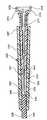
도 1 은 본 발명의 캐뉼러 밀봉 시일드 조립체 및 피하 시린지의 확대된 사시도이다.1 is an enlarged perspective view of a cannula seal sheath assembly and a hypodermic syringe of the present invention.
도 2 는 피하 시린지에 부착된 본 발명의 캐뉼러 밀봉 시일드 조립체의 측면도이다.2 is a side view of the cannula seal sheath assembly of the present invention attached to the hypodermic syringe.
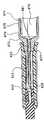
도 3 은 3 - 3 선을 따라 취한 도 2의 시린지 및 캐뉼러 조립체의 횡단면도이다.Figure 3 is a cross-sectional view of the syringe and cannula assembly of Figure 2 taken along
도 4 는 기부 캐뉼러 밀봉 위치의 밀봉 플러그를 나타내는 도 3의 시린지 및 캐뉼러 조립체이다.Figure 4 is the syringe and cannula assembly of Figure 3 showing the sealing plug at the base cannula sealing position.
도 5 는 임의의 바늘 캐뉼러 조립체를 나타낸다.Figure 5 shows an optional needle cannula assembly.
도 6 은 표준적인 피하 주사 바늘을 나타낸다.Figure 6 shows a standard hypodermic needle.
도 7 및 도 8 은 본 발명의 캐뉼러 밀봉 시일드 조립체의 임의의 구체예에 대한 횡단면도이다.Figures 7 and 8 are cross-sectional views of any embodiment of the cannula seal sheath assembly of the present invention.
도 9 및 도 10 은 본 발명의 캐뉼러 밀봉 시일드 조립체의 다른 임의의 구체예에 대한 횡단면도이다.9 and 10 are cross-sectional views of any other embodiment of the cannula seal sheath assembly of the present invention.
도 11 은 캐뉼러의 루멘을 밀봉시킬 수 있는 본 발명의 밀봉 플러그에 대한 임의의 구체예의 횡단면도이다.11 is a cross-sectional view of any embodiment of a sealing plug of the present invention that is capable of sealing the lumen of the cannula.
도 12는 바늘 캐뉼러에 영구적으로 장착된 시린지 배럴과 사용되는 본 발명의 캐뉼러 밀봉 시일드 조립체에 대한 횡단면도이다.12 is a cross-sectional view of the cannula seal sheath assembly of the present invention used with a syringe barrel permanently mounted on a needle cannula;
본 발명은 다양한 형태의 구체예에 의하여 만족될 수 있지만, 도면에 의하여나타내었으며 본원은 본 발명의 원리를 예시한 것일 뿐 본 발명의 범위를 제한하는 것은 아니라는 것을 밝혀두면서 본 원의 바람직한 구체예를 상술하였다. 본 발명의 범위는 첨부된 청구항들 및 이의 균등 범위에 의하여 결절될 것이다.While the present invention has been shown and described with reference to certain preferred embodiments thereof, it will be understood by those of ordinary skill in the art that various changes in form and details may be made therein without departing from the spirit and scope of the invention as defined by the following claims. Described above. The scope of the invention will be dictated by the appended claims and their equivalents.
도 1 - 도 4 에서, 캐뉼러 밀봉 시일드 조립체 (20) 는 기부 말단 (23), 원위 말단 (25) 및 이들 사이의 루멘 (27)을 갖는 캐뉼러 (22) 를 포함하는 캐뉼러 조립체 (21) 를 포함한다. 허브 (28) 는 상기 캐뉼러의 기부 말단 (23) 과 연결된 원위 말단 (31) 및 개구부 기부 말단 (29) 을 가지므로 상기 루멘은 상기 허브의 개구부 기부 말단 (23) 과 연결되어 유체내에 존재한다. 이후 더욱 상세히 설명될 바와 같이, 허브 (28) 는 상기 시린지 배럴 또는 다른 유체 운반 장치의 로킹 루어 타입 칼라를 합체시키는 방사상 돌출부 (32) 를 포함한다. 상기 구체예에서, 캐뉼러의 원위 말단 (25) 은 블런트 팁 (33) 을 포함하는 것이 바람직하며, 캐뉼러 및 허브는 열가소성 재료로 일체 성형 제조하는 것이 바람직하다. 그러나, 상기 캐뉼러 및 허브는 독립적으로 제조될 수 있으며 이후 에폭시와 같은 접착제로 연결되거나 또는 기계적으로 연결된다.1 to 4, a cannula
시일드 (35) 는 개구부 기부 말단 (37), 개구부 원위 말단 (38) 및 이들 사이에 상기 시일드내 리세스를 한정하는 측벽 (39) 을 포함한다. 상기 시일드는 분리 가능하도록 캐뉼러 조립체와 연결되므로 캐뉼러의 원위 말단 (25) 은 상기 시일드의 리세스 (40) 내에 포함된다. 밀봉 플러그 (seal plug ; 43) 기부 말단 (44) 및 원위 말단 (45) 을 포함한다. 도 3 에 나타낸바와 같이, 밀봉 플러그는원위 배치되는데, 상기 밀봉 플러그는, 도 4 에 나타낸바와 같이, 원위 위치에서 기부 위치로 포개짐 이동 (telescoping movement) 되도록 시일드 (35) 의 원위 말단 (38) 에서 원위적이고 외향적으로 돌출된다. 밀봉 플러그는 기부 위치에 있을 경우 시일드 외부 및 캐뉼러 루멘 (27) 사이에서 가압되지 않은 유체가 소통되는 것을 방지하기 위하여 캐뉼러를 밀봉시키는 수단을 포함한다. 상기 구체예에서, 밀봉 수단은 밀봉 플러그의 기부 말단 (44) 으로부터 원위적으로 뻗은 보유관 (46) 을 포함한다. 상기 보유관은 도 4에 나타낸 바와 같이 밀봉 플러그가 기부 위치에 있을 경우 캐뉼러의 원위 말단과 밀봉 합체되기 위한 내부 표면 (47) 을 포함한다. 밀봉 플러그가 원위 위치에서 기부 밀봉 위치로 이동될 경우 캐뉼러의 원위 말단을 보유관으로 삽입시키기 위하여 밀봉 플러그의 기부 말단에 끝이 뾰족한 부분 (46) 을 포함하는 것이 바람직하다.The
어떠한 경우에는, 구조를 제공하거나 또는 구성 부분들을 배치시키면, 캐뉼러 밀봉 시일드 조립체를 보통으로 사용할 경우, 밀봉 플러그가 이의 기부 밀봉 위치로부터 원위 위치로 이동될 수 없게된다.In some cases, providing the structure or disposing the components causes the sealing plug to be unable to move from its base sealing position to the distal position when the cannula sealing shield assembly is normally used.
밀봉 플러그가 기부 밀봉 위치로부터 원위 위치까지 이동시키는 것을 방지하는 방법은 다양한 구조 및 배치에 의하여 수행가능하다. 바람직한 구조물에는 밀봉 플러그 (43) 를 포함하므로 이것이 손가락 모양의 접촉 표면 (50) 에 디지탈 방식의 압력을 가하여 도 3 의 원위 위치로부터 도 4 의 기부 밀봉 위치로 삽입될 때, 상기 플러그는 실질적으로 시일드 (35) 의 개구부 기부 말단 (38) 내부에 남아있게 된다. 상기 위치에서, 사용자는 상기 플러그를 움켜잡고 이의 원위 위치로 뺄 수 없게 된다. 또한, 상호 작용하는 구조는 시일드 및 밀봉 플러그 사이에 제공되어기부 밀봉 위치에 있는 밀봉 플러그를 잠그는 것을 도울 수 있을 것이다. 이러한 구조는 하기 더욱 상술할 바와 같이, 상기 밀봉 플러그가 이의 기부 밀봉 위치에 존재할 경우, 밀봉 플러그 상의 돌출부 및 / 또는 리세스와 합체되는 리세스 및 / 또는 돌출부를 시일드 상에 포함할 수 있다.The method of preventing the sealing plug from moving from the base sealing position to the distal position can be performed by various structures and arrangements. The preferred structure includes a
밀봉 플러그는 시일드 및 밀봉 플러그 사이의 기계적인 상호 작용, 예를 들어서 간섭 구조 (interfering structure), 마찰, 나사형 등에 의하여 이의 원위 위치에 장착될 수 있다. 이러한 구체예에서, 시일드는 상기 밀봉 플러그내에 내부로 뻗은 환상 돌출부 (41) 및 환상 리세스 (51) 를 포함한다. 도 3 에 나타낸 바와 같이, 상기 밀봉 플러그가 이의 원위 위치에 존재할 경우, 시일드내 환상 돌출부 (41) 는 밀봉 플러그내 환상 리세스 (51) 와 합체되어, 상기 밀봉 플러그를 시일드와 관련된 축상 위치에 장착시킬 수 있다. 상기 돌출부는 시일드내 플러그의 재료 선택 및 구조적 형태에 따라 분리된 돌기 형태로부터 완전한 환형 고리까지, 또는 톱니형 고리와 같이 어떠한 형태일 수 있다. 이와 유사하게, 시일드내 리세스는 시일드내 돌출부와 적당히 상호 작용하도록 하는 다양한 형태를 취할 수 있다. 상기 구조는 또한 역으로되어 플러그가 돌출부를 포함하고 시일드가 리세스를 포함할 수 있다.The sealing plug may be mounted in its distal position by a mechanical interaction between the shield and the sealing plug, for example by an interfering structure, friction, threaded or the like. In this embodiment, the seal includes an
본 발명의 밀봉 시일드 조립체는 시린지와 같은 다양한 유체 운반 장치와 함께 사용하기에 적당하다. 설명을 위하여, 캐뉼러 밀봉 시일드 조립체 (20) 를 원위 말단 (73), 기부 말단 (74) 및 유체 보유 챔버 (76) 를 한정하는 환형 측벽이 존재하는 시린지 배럴을 포함하는 피하 시린지 (70) 에 연결시켰다. 부피 측정 표지(72) 는 운반되거나 또는 받아들일 유체의 양을 측정하기 위하여 배럴상에 존재한다. 상기 시린지 배럴의 원위 말단은 허브 (28)에 연결되어 캐뉼러 루멘(22) 은 시린지 배럴의 챔버 (76) 와 연결되어 유체내에 존재한다. 상기 구체예에서, 시린지 배럴의 원위 말단 (73) 은 유체가 상기 캐뉼러 및 상기 챔버 사이를 통과하도록 하는 관 (78) 을 갖는 프러스토-원뿔형 팁 (77) 을 포함하는 것이 바람직하다. 시린지 배럴의 프러스토-원뿔형 팁 (frusto-conically shaped tip) 은 허브의 개구부 기부 말단 (29) 의 프러스토 - 원뿔형 표면 (30) 과 합체되는 것이 바람직하다. 시린지 배럴의 원위 말단은 또한 바람직하게는, 꼭 그러해야 하는 것은 아니지만, 팁 (77) 을 동심적으로 포위하는 로킹 (locking) 루어 타입 칼라 (luer-type collar ; 79) 를 포함하는 것이 바람직하다. 상기 루어 칼라는 상기 허브를 상기 배럴에 안전하게 장착시키기 위하여 허브 (28) 상에 방사형 돌출부 (32) 와 합체되는 내부 나사형 부분 (80) 이 존재한다. 다양한 의료용 유체 취급 장치에 부착되는 다양한 형태의 허브를 포함하는 것은 본 발명의 범위내에 포함된다. 프러스토-원뿔형 내부 공동이 존재하는, 상기된 허브 형태는 다음과 같이 많은 가능성을 내포한다. 스톱 콕크 (stopcocks) 및 어뎁터 9adapter) 와 같은, 다수의 시린지 및 유체 취급 장치들은 프러스토-원뿔형 내부 공동이 존재하는 허브가 적당히 합체될 루어 슬립 (luer slip) 또는 로킹 루어 - 타입 합체물을 포함한다. 시린지 배럴과 함께 일체 성형 제조되는, 캐뉼러 밀봉 시일드 및 시린지 조립체를 제공하는 것은 본 발명의 범위내에 존재한다. 뿐만아니라 캐뉼러가 시린지 배럴 팁에 영구적으로 부착되어 있는 조립체와 같은 것을 제공하는 것도 본 발명의 범위에 포함된다.The seal-sealed assemblies of the present invention are suitable for use with a variety of fluid delivery devices, such as syringes. A description is given of a
마개 (82) 는 환형 측벽 (75) 과 합체되어 유체가 가득찬 합체물을 밀어내는 챔버 (76) 위치에 위치한다. 가늘고 긴 플런저 막대 983)는 마개와 연결되어 배럴 (71) 의 개구부 기부 말단쪽으로 뻗어있다. 마개 및 플런저 막대는 1 조각 일체 구조물 (one-piece unitary construction) 로서 제조될 수 있다. 상기 플런저 막대에 적용되는 힘에 의하여 상기 마개는 기부 방향으로 미끄러져 이동하여 상기 관 (78)을 통하여 챔버 (76) 로 유체를 인수하게 된다. 역으로, 원위 방향으로 마개 (82)를 미끄러져 이동시키면 유체는 챔버 (76) 로부터 관 (78) 을 통하여 이동된다.The
사용할 때, 시린지 (70) 는 부착된 형태의 또는 분리된 상태의 캐뉼러 조립체를 사용하는 다수의 공지된 방법으로 의약품 또는 다른 액체로 충전될 수 있다. 충전시킨 후, 시일드가 분리된, 상기 시린지 및 캐뉼러 조립체는 캐뉼러의 원위 말단이 날카롭게 만들어졌을 경우, 피부를 통해 직접적으로 또는 I.V. 세트 또는 다른 장치의 관통 가능한 격막을 통하여 환자에게 의약품 또는 기타 액체를 즉시 운반하는데 사용될 수 있다. 상기 캐뉼러 원위 말단이 블런트할 경우, 의약품 또는 다른 액체는 업계에 공지된 미리 - 흠집을 낸 (pre-slit) 격막이 존재하는 I.V. 세트를 포함하는 다양한 유체 운반 장치를 통하여 운반될 수 있다. 도 1 - 도 4 의 구체예의 시일드는 필요한 만큼 많이 시린지를 충전시킨 후 의약품을 운반하는 경우 또는 다른 액체를 환자에게 투여하는 경우, 분리 및 장착될 수 있다. 사용자가 상기 밀봉 플러그를 원위 위치로부터 기부 위치로 이동시켜 캐뉼러를 밀봉시킬지의 여부를 선택하는 것은 본 발명의 중요한 특징이다. 이러한 이동은 밀봉 플러그의 접촉 표면을 압축시켜 밀봉 플러그를 기부 방향으로 이동시켜 수행가능하다. 시린지를 충전시킨후 의약품 또는 액체를 투약하는 기간을 연장시킬 수도 있다. 이러한 기간 동안에 사용자는 가압되지 않은 유체가 캐뉼러의 원위 말단을 통하여 배출되는 것을 방지할 수 있다. 상기 밀봉 플러그를 기부 위치로 이동시킴으로써 상기 캐뉼러는 밀봉되어 가압되지 않은 유체가 시일드의 루멘 및 외부 사이에서 소통되는 것을 방지할 수 있다. 사용할 때, 상기 시일드는 분리되어 캐뉼러를 노출시킬 수 있다.In use, the
도 5 는 바람직하게는 스테인레스 스틸과 같은 금속으로 제조된 금속성 캐뉼러 (122), 및 열가소성 재료로 제조되는 것이 바람직한 허브 (128) 를 포함하는 임의의 캐뉼러 조립체 (121) 를 나타낸다. 캐뉼러 (122) 는 기부 말단 (123) 및 원위 말단 (125) 을 포함하는데, 이들 사이에는 루멘이 존재한다. 원위 말단 (125) 은 블런트 틉 (133) 을 포함한다. 캐뉼러 조립체 (121) 는 도 1 - 도 4 의 구체예의 캐뉼러 조립체 (21) 와 유사한 기능을 갖는다. 실질적으로 내구력이 여전히 존재할 경우 상기 캐뉼러의 외부 지름은 더 작게 그리고 루멘 지름은 크게 제조되도록 하는 상기 캐뉼러의 열가소성 캐뉼러에 대한 내구력상의 이점 때문에 스테인리스 스틸 캐뉼러가 바람직하다.FIG. 5 shows an
도 6 은 의약품을 환자에 투여하거나 유체를 의약품 바이알 및 I.V. 세트에 존재하는 격막과 같은 관통 가능한 격막을 통하여 유체를 운밥ㄴ하는데 통상적으로 사용되는 선행 기술의 바늘 조립체 (221) 을 나타낸다. 바늘 조립체 (221) 는 기부 말단(223), 원위 말단(225) 및 이들 사이에 루멘이 존재하는 바늘 캐뉼러 (222) 를 포함한다. 바늘 조립체 (221) 는 또한 개구부 기부 말단 (229) 및 캐뉼러의 기부말단과 연결된 원위 말단 (231) 이 존재하는 허브 (228) 도 또한 포함한다. 상기 캐뉼러의 원위 말단 (225) 은 피부, 마개 및 격막을 관통할 수 있는 날카로운 모서리 (223) 를 추가로 포함한다.FIG. 6 illustrates a method of administering a medicament to a patient or dispensing fluids into a pharmaceutical vial and IV. And a needle assembly 221 of the prior art conventionally used to infuse fluid through a perforatable diaphragm, such as the diaphragm present in the set. Needle assembly 221 includes a
본 발명의 캐뉼러 밀봉 시일드 조립체의 바람직한 구체예는 블런트 캐뉼러가 존재하는 캐뉼러 조립체를 포함한다. 그러나, 캐뉼러 조립체 (221)와 같은 날카로운 원위 말단이 존재하는 캐뉼러 조립체를 포함하는 캐뉼러 밀봉 시일드 조립체를 포함하는 것은 본 발명의 범위 내에 존재한다.A preferred embodiment of the cannula seal sheath assembly of the present invention includes a cannula assembly in which blunt cannulas are present. However, it is within the scope of the present invention to include a cannula seal shield assembly including a cannula assembly in which sharp distal ends, such as cannula assembly 221, are present.
도 7 - 도 8 은 도 1 - 도 4 의 구체예와 기능적으로 유사한 임의의 캐뉼러 밀봉 시일드 조립체 (320) 를 나타낸다. 기술하기 위하여, 캐뉼러 밀봉 시일드 조립체 (320)를 유체를 보유하기 위한 챔버 (376) 를 한정하는 가늘고 긴 실린더 몸통, 개구부 기부 말단, 원위 말단 (373) 이 존재하는 시린지 (370) 와 연결시킨다. 프러스토 - 원뿔형 팁 (377) 은 원위 말단으로부터 뻗어나와 있으며 챔버 (376) 와 연결되어 유체내에 존재하는 관 (378) 이 존재한다. 캐뉼러 조립체 (321) 는 날카로운 모서리 (333) 를 포함하는 원위 말단 (325) 이 존재하는 캐뉼러 (322) 를 포함한다. 상기 시일드 (335) 는 개구부 기부 말단 (337), 개구부 원위 말단 (338) 및 시일드내 리세스 (340) 를 한정하는 이들 사이에 측벽 (339) 이 존재한다. 상기 시일드는 상기 캐뉼러 조립체와 분리 가능하도록 연결되어 캐뉼러의 원위 말단은 상기 리세스내에 포함된다.FIGS. 7-8 illustrate any cannula
밀봉 플러그 (seal plug ; 343)는 기부 말단 (344) 을 포함하며, 기부 표면 (348) 및 원위 말단 (345) 이 존재한다. 밀봉 플러그가 이의 기부 위치에 있을때시일드의 외부 및 루멘 사이에서 가압되지 않은 (unpressurized) 유체가 소통되는 것을 방지하기 위하여 캐뉼러의 원위 말단을 밀봉시키며 밀봉 플러그는 도 7 에 나타낸, 원위 위치에서 도 8 에 나타낸, 기부 위치로 포개짐 이동 (telescoping movement) 되기 위하여 시일드의 원위 말단으로부터 원위적이며 외향적으로 돌출되어 원위 배치된다. 상기 구체예에서, 밀봉 플러그 (343) 가 도 8 에 기술된 바와 같이, 기부 위치에 존재하기에 충분하도록 캐뉼러가 길어서, 상기 캐뉼러의 원위 말단이 밀봉 플러그의 기부 위치에 합체되도록 배치된다. 캐뉼러 원위 말단의 날카로운 모서리 (333) 의 형태 및 밀봉 플러그의 형태 및 재료에 따라서, 주사 바늘 부분을 상기 밀봉 플러그에 합체시키면 상기 밀봉 플러그는 캐뉼러 원위 말단의 외부 표면과 밀봉 합체되어 루멘 또는 외부 표면 모두를 차단시켜 가압되지 않은 유체가 시일드의 외부 및 루멘 사이에서 소통되는 것을 방지할 것이다. 상기 캐뉼러 밀봉 시일드 조립체는 도 1 - 도 4 의 구체예와 유사한 방식으로 사용될 것이다.The
예를 들어, 천연 고무, 합성 고무, 열가소성 탄성체와 같은, 본 발명의 밀봉 플러그를 주조하기 위하여 사용될 수 있는 재료의 범위가 다양함에도 불구하고, 본 발명의 구체예의 밀봉 플러그 (343) 용 재료로서 천연 고무, 합성 고무, 열가소성 탄성체와 같은 열가소성이며 더욱 유연한 재료가 바람직하다. 재료가 더욱 유연하며 더욱 탄성을 갖는 경우, 캐뉼러 원위 말단은 더욱 용이하게 상기 밀봉 플러그 기부 말단에 합체될 것이다. 상기 밀봉 플러그는 예를 들어, 기부 표면용인 열가소성 재료와 탄성체 삽입물과 같이 2가지 재료로 제조될 수 있다.Although the range of materials that may be used to cast the sealing plug of the present invention, such as natural rubber, synthetic rubber, thermoplastic elastomer, for example, varies, it is preferred that the material of the sealing
도 9 및 도 10 은 임의의 캐뉼러 밀봉 시일드 및 시린지 조립체를 나타낸다.상기 구체예는 캐뉼러 (422) 및 허브 (428) 가 시린지 배럴 (471) 과 함께 일체 성형 제조된다는 것을 제외하고 도 1 - 도 4 의 구체예와 유사한 기능을 갖는다. 시일드 (435) 는 개구부 기부 말단 (437), 개구부 원위 말단 (438) 및 이들 사이에 상기 시일드내 리세스 (440) 를 한정하는 측벽 (439) 을 갖는다. 밀봉 플러그 (434) 는 기부 말단 (444) 및 원위 말단 (445) 를 포함한다. 상기 밀봉 플러그는 도 10 에 나타낸 바와 같은, 기부 위치로 포개짐 이동 (telescoping movement) 되기 위하여 도 9 에 나타낸 바와 같은, 시일드의 원위 말단 (438) 으로부터 원위적이며 외향적으로 돌출되어 원위 배치된다.9 and 10 illustrate any of the cannula sealing seals and syringe assemblies that are shown in Figure 1 except that the
도 11 은 캐뉼러 밀봉 시일드 조립체인 본 발명의 임의의 구체예를 나타낸다. 상기 구체예는 개구부 기부 말단 (537), 개구부 원위 말단 (538) 및 이들 사이에 상기 시일드내 리세스를 한정하는 측벽 (539) 이 존재하는 시일드 (535) 를 포함한다. 밀봉 플러그 (543) 는 기부 말단 (544) 및 원위 말단 (545)을 포함한다. 밀봉 플러그 (543) 은 또한 상기 밀봉 플러그의 기부 말단상에서 기부 방향으로 돌출된 돌출부 (552) 도 포함한다. 돌출부 (522) 는 밀봉 플러그가 기부 위치 즉, 돌출부 (522) 가 캐뉼러 (522) 의 루멘 (527) 에 존재하도록 배치된다. 도 11의 구체예는 또한 상기 밀봉 플러그가 기부 밀봉 위치로부터 원위 위치로 이동하는 것을 방지하는 수단을 포함한다. 상기 구체예에서 이러한 이동을 방지하는 수단에는 상기 시일드 내부로 돌출된 환상 리브 (annular rib ; 542) 및 상기 밀봉 플러그내 환상 리세스 (553) 를 포함한다. 손가락 모양의 접촉 표면 (550) 에 압력을 가하여 상기 밀봉 플러그를 이의 기부 캐뉼러 밀봉 위치로 이동시킬 때, 내부로 돌출된 환상 리브 (542) 는 환상 리세스 (553) 내부로 삽입되어 상기 밀봉 플러그를 기부 위치로 로킹 (locking) 시킨다.Figure 11 shows an embodiment of the present invention which is a cannula seal sealed assembly. The embodiment includes a
도 12는 다른 임의의 캐뉼러 밀봉 시일드 및 시린지 조립체를 나타내는데, 피하 시린지 (670) 는 가늘고 긴 실린더형 몸체 또는 유체 보유 챔버 (676) 를 한정하는 측벽 (675) 이 존재하는 시린지 배럴 (671) 을 포함한다. 배럴 (671) 은 상기 챔버 (676) 와 연결된 릴 통로 (681) 를 포함하는 원위적으로 돌출된 팁 (677) 이 존재하는 원위 말단을 포함한다. 캐뉼러 (622) 는 원위 말단 (625) 및 상기 시린지 배럴의 팁 (677) 에 부착되어 고정된 기부 말단 (623) 을 포함한다. 상기 구체예에서 캐뉼러 기부 말단은 팁 통로 (681) 내에 위치하며 이곳에 기계적 수단 또는 에폭시와 같은 접착제로써 장착된다. 상기 구체예에서, 상기 시린지 배럴은 바람직하게는 유리 또는 플라스틱으로 제조되는 것이 바람직하며 상기 캐뉼러는 스테인레스 스틸과 같은 금속으로 제조되며 날카로운 팁 (633) 을 포함하는 것이 바람직하다. 사용할 때, 상기 구체예의 조립체는 도 11의 구체예의 조립체와 유사한 기능을 갖는다.12 depicts any other cannula sealing seal and syringe assembly wherein the
본 발명은 캐뉼러, 시일드 (shield) 및 밀봉 플러그 (sealing plug)를 포함하는 캐뉼러 밀봉 시일드 조립체에 관한다. 캐뉼러 조립체는 기부 말단, 원위 말단 및 이들 사이에 루멘을 갖는 캐뉼러 (cannula), 및 개구부 기부 말단 및 캐뉼러 기부 말단과 연결된 원위 말단을 갖는 허브 (hub) 를 포함하므로 상기 루멘이 상기 허브의 개구부 기부 말단과 연결되어 유체내에 존재하는 캐뉼러를 포함한다. 상기시일드는 개구부 기부 말단, 개구부 원위 말단을 가지며 이들 사이에는 시일드내 리세스를 한정하는 측벽이 존재한다. 상기 시일드는 캐뉼러 조립체에 분리 가능하도록 연결되므로 캐뉼러 원위 말단은 상기 리세스내에 포함된다. 밀봉 플러그는 기부 말단 및 원위 말단이 존재한다. 상기 밀봉 플러그는 원위 말단으로부터 기부 말단으로 포개짐 이동 (telescoping movement) 되도록 시일드의 원위 말단으로부터 원위적이며 외향적으로 돌출되어 원위 배치되어 있다. 밀봉 플러그는 밀봉 플러그가 기부 위치에 존재할 경우 밀봉 플러그의 외부 및 캐뉼러 루멘 사이에서 가압되지 않은 (unpressurized) 유체가 소통되는 것을 방지하기 위하여 캐뉼러를 밀봉시키는 구조물을 포함한다.The present invention relates to a cannula seal shield assembly including a cannula, a shield, and a sealing plug. The cannula assembly includes a cannula having a base end, a distal end and a lumen therebetween, and a hub having an opening base end and a distal end coupled to the cannula base end, And a cannula connected to the opening base end and present in the fluid. The seal has an opening base end, an opening distal end and a sidewall therebetween defining a seal drain recess. The seal is releasably connected to the cannula assembly so that the distal end of the canula is contained within the recess. The sealing plug has a base end and a distal end. The sealing plug is distal and projecting distally and outwardly from the distal end of the shield to provide a telescoping movement from the distal end to the base end. The sealing plug includes a structure that seals the cannula to prevent unpressurized fluid from communicating between the exterior of the sealing plug and the cannula lumen when the sealing plug is in the base position.
본 발명의 또다른 구체예에는 시린지 배럴 (syringe barrel), 캐늘러 (cannula), 시일드 (shield) 및 밀봉 플러그를 포함하는 캐뉼러 밀봉 시일드 및 시린지 조립체를 포함한다. 상기 시린지 배럴은 유체를 보유하는 챔버를 한정하는 가늘고 긴 몸통, 및 이로부터 뻗어나온 팁을 갖는 원위 말단 및 개구부 기부 말단을 포함한다. 상기 팁은 챔버와 연결되어 유체내에 존재하는 통로를 포함한다. 상기 캐뉼러는 기부 말단, 원위 말단이 존재하며 이들 사이에 루멘이 존재한다. 상기 캐뉼러의 기부 말단은 시린지 배럴의 팁에 연결되므로 상기 루멘은 챔버와 연결되어 유체내에 존재한다. 상기 시일드는 개구부 기부 말단, 개구부 원위 말단 및 시일드내 리세스를 한정하는 측벽을 갖는다. 상기 시일드는 시린지 배럴의 팁과 분리 가능하도록 연결되었으므로 상기 캐뉼러의 원위 말단은 리세스내에 포함되어 있다. 상기 밀봉 플러그는 기부 말단 및 원위 말단이 존재한다.Yet another embodiment of the present invention includes a cannula sealing seal and a syringe assembly including a syringe barrel, a cannula, a shield, and a sealing plug. The syringe barrel includes an elongated body defining a chamber for retaining fluid, and a distal end and an opening base end with a tip extending therefrom. The tip includes a passage in fluid communication with the chamber. The cannula has a base end, distal end, and a lumen therebetween. The base end of the cannula is connected to the tip of the syringe barrel so that the lumen is in fluid communication with the chamber. The seal has a sidewall defining an opening base end, an opening distal end, and a seal drain recess. The seal is removably connected to the tip of the syringe barrel so that the distal end of the cannula is contained within the recess. The sealing plug has a base end and a distal end.
상기 밀봉 플러그는 시일드와 관련하여 원위 배치되는데, 상기 밀봉 플러그는 원위 위치로부터 기부 위치로 포개짐 이동되도록 시일드의 원위 말단으로부터 원위적이고 외향적으로 돌출되어 있다. 상기 플러그는 상기 플러그가 기부 위치에 존재할 경우 시일드 외부 및 루멘 사이에서 가압되지 않은 유체가 소통되는 것을 방지하기 위하여 상기 캐뉼러를 밀봉시키는 구조물을 포함한다.The sealing plug is distal with respect to the shield, the sealing plug projecting distally and outwardly from the distal end of the shield to be superimposed from the distal position to the base position. The plug includes a structure that seals the cannula to prevent unpressurized fluid from communicating between the sealed exterior and the lumen when the plug is in the base position.
Claims (1)
Translated fromKoreanApplications Claiming Priority (3)
| Application Number | Priority Date | Filing Date | Title |
|---|---|---|---|
| US08/839,223US5858008A (en) | 1997-04-22 | 1997-04-22 | Cannula sealing shield assembly |
| US08/839,223 | 1997-04-22 | ||
| US8/839,223 | 1997-04-22 |
Publications (2)
| Publication Number | Publication Date |
|---|---|
| KR19980079299A KR19980079299A (en) | 1998-11-25 |
| KR100408924B1true KR100408924B1 (en) | 2004-03-22 |
Family
ID=25279180
Family Applications (1)
| Application Number | Title | Priority Date | Filing Date |
|---|---|---|---|
| KR1019970034270AExpired - Fee RelatedKR100408924B1 (en) | 1997-04-22 | 1997-07-22 | Cannula seal seal assembly |
Country Status (10)
| Country | Link |
|---|---|
| US (1) | US5858008A (en) |
| EP (1) | EP0873757B1 (en) |
| JP (1) | JP3083134B2 (en) |
| KR (1) | KR100408924B1 (en) |
| AU (1) | AU735857B2 (en) |
| BR (1) | BR9704042A (en) |
| CA (1) | CA2209956C (en) |
| DE (1) | DE69725282T2 (en) |
| SG (1) | SG66379A1 (en) |
| TW (1) | TW410164B (en) |
Families Citing this family (98)
| Publication number | Priority date | Publication date | Assignee | Title |
|---|---|---|---|---|
| US6071300A (en)* | 1995-09-15 | 2000-06-06 | Sub-Q Inc. | Apparatus and method for percutaneous sealing of blood vessel punctures |
| US6162192A (en) | 1998-05-01 | 2000-12-19 | Sub Q, Inc. | System and method for facilitating hemostasis of blood vessel punctures with absorbable sponge |
| US6183497B1 (en)* | 1998-05-01 | 2001-02-06 | Sub-Q, Inc. | Absorbable sponge with contrasting agent |
| US6071301A (en) | 1998-05-01 | 2000-06-06 | Sub Q., Inc. | Device and method for facilitating hemostasis of a biopsy tract |
| US7468055B2 (en)* | 1996-06-20 | 2008-12-23 | Becton Dickinson And Company | Multi-beveled point needle and syringe having a multi-beveled point needle |
| US6629963B2 (en)* | 1996-06-20 | 2003-10-07 | Becton, Dickinson And Company | Syringe and needle shield assembly and method of sterilizing such assembly |
| US6071574A (en)* | 1997-07-11 | 2000-06-06 | Southpac Trust International, Inc. | Folded corrugated material and method for producing same |
| US7625352B1 (en) | 1998-05-01 | 2009-12-01 | Sub-Q, Inc. | Depth and puncture control for system for hemostasis of blood vessel |
| US6610026B2 (en) | 1998-05-01 | 2003-08-26 | Sub-Q, Inc. | Method of hydrating a sponge material for delivery to a body |
| US6200328B1 (en) | 1998-05-01 | 2001-03-13 | Sub Q, Incorporated | Device and method for facilitating hemostasis of a biopsy tract |
| US20010045575A1 (en) | 1998-05-01 | 2001-11-29 | Mark Ashby | Device and method for facilitating hemostasis of a biopsy tract |
| US6315753B1 (en)* | 1998-05-01 | 2001-11-13 | Sub-Q, Inc. | System and method for facilitating hemostasis of blood vessel punctures with absorbable sponge |
| JP4271375B2 (en)* | 1999-02-10 | 2009-06-03 | サブ−キュー・インコーポレーテッド | Device and method for facilitating hemostasis in a biopsy duct |
| DE19927201A1 (en)* | 1999-06-15 | 2001-01-25 | Schott Glas | Syringe for medical purposes |
| US6984219B2 (en) | 1999-09-23 | 2006-01-10 | Mark Ashby | Depth and puncture control for blood vessel hemostasis system |
| US7695492B1 (en) | 1999-09-23 | 2010-04-13 | Boston Scientific Scimed, Inc. | Enhanced bleed back system |
| AU1569301A (en)* | 1999-11-05 | 2001-06-06 | Eli Lilly And Company | Teat infusion syringe and related components |
| ES1045206Y (en)* | 2000-02-02 | 2001-02-01 | Fada Italia S R L | PERFECTED DISPOSABLE SYRINGE. |
| US6702785B1 (en)* | 2000-05-04 | 2004-03-09 | Collins Sonya Dene | Needle capper |
| US6540735B1 (en) | 2000-05-12 | 2003-04-01 | Sub-Q, Inc. | System and method for facilitating hemostasis of blood vessel punctures with absorbable sponge |
| US7201725B1 (en) | 2000-09-25 | 2007-04-10 | Sub-Q, Inc. | Device and method for determining a depth of an incision |
| US8187625B2 (en)* | 2001-03-12 | 2012-05-29 | Boston Scientific Scimed, Inc. | Cross-linked gelatin composition comprising a wetting agent |
| WO2002087636A1 (en)* | 2001-03-12 | 2002-11-07 | Sub-Q, Inc. | Methods for sterilizing cross-linked gelatin compositions |
| USD454394S1 (en) | 2001-03-19 | 2002-03-12 | Becton Dickinson And Company | Needle cover |
| US7029489B1 (en) | 2001-05-18 | 2006-04-18 | Sub-Q, Inc. | System and method for delivering hemostasis promoting material to a blood vessel puncture site |
| US6863680B2 (en) | 2001-11-08 | 2005-03-08 | Sub-Q, Inc. | System and method for delivering hemostasis promoting material to a blood vessel puncture site by fluid pressure |
| US7008440B2 (en) | 2001-11-08 | 2006-03-07 | Sub-Q, Inc. | System and method for delivering hemostasis promoting material to a blood vessel puncture site by fluid pressure |
| US7192436B2 (en)* | 2001-11-08 | 2007-03-20 | Sub-Q, Inc. | Pledget-handling system and method for delivering hemostasis promoting material to a blood vessel puncture site by fluid pressure |
| US7025748B2 (en)* | 2001-11-08 | 2006-04-11 | Boston Scientific Scimed, Inc. | Sheath based blood vessel puncture locator and depth indicator |
| US7037322B1 (en) | 2001-11-08 | 2006-05-02 | Sub-Q, Inc. | System and method for delivering hemostasis promoting material to a blood vessel puncture with a staging tube |
| US7037323B2 (en)* | 2001-11-08 | 2006-05-02 | Sub-Q, Inc. | Pledget-handling system and method for delivering hemostasis promoting material to a blood vessel puncture site by fluid pressure |
| US20040102730A1 (en)* | 2002-10-22 | 2004-05-27 | Davis Thomas P. | System and method for facilitating hemostasis of blood vessel punctures with absorbable sponge |
| US8317821B1 (en) | 2002-11-04 | 2012-11-27 | Boston Scientific Scimed, Inc. | Release mechanism |
| US7955353B1 (en) | 2002-11-04 | 2011-06-07 | Sub-Q, Inc. | Dissolvable closure device |
| US7455680B1 (en) | 2002-11-04 | 2008-11-25 | Boston Scientific Scimed, Inc. | Apparatus and method for inhibiting blood loss |
| US6951228B2 (en)* | 2003-12-04 | 2005-10-04 | B Braun Medical Inc. | Bulk compounder manifold |
| US7875043B1 (en) | 2003-12-09 | 2011-01-25 | Sub-Q, Inc. | Cinching loop |
| US20050222539A1 (en)* | 2004-03-30 | 2005-10-06 | Pediamed Pharmaceuticals, Inc. | Automatic injection device |
| FR2913200B1 (en)* | 2007-03-02 | 2009-12-11 | Becton Dickinson France | NEEDLE PROTECTION DEVICE |
| US9345836B2 (en) | 2007-10-02 | 2016-05-24 | Medimop Medical Projects Ltd. | Disengagement resistant telescoping assembly and unidirectional method of assembly for such |
| US7967795B1 (en) | 2010-01-19 | 2011-06-28 | Lamodel Ltd. | Cartridge interface assembly with driving plunger |
| US10420880B2 (en) | 2007-10-02 | 2019-09-24 | West Pharma. Services IL, Ltd. | Key for securing components of a drug delivery system during assembly and/or transport and methods of using same |
| US9656019B2 (en) | 2007-10-02 | 2017-05-23 | Medimop Medical Projects Ltd. | Apparatuses for securing components of a drug delivery system during transport and methods of using same |
| BRPI0817907B8 (en) | 2007-10-02 | 2021-06-22 | Lamodel Ltd | apparatus for administering a substance to an individual |
| DK2240222T3 (en) | 2008-01-11 | 2018-06-25 | Ucb Biopharma Sprl | SYSTEMS FOR THE ADMINISTRATION OF PHARMACEUTICALS FOR PATIENTS WITH RHEUMATOID ARTHRITIS |
| US8012129B2 (en)* | 2008-06-25 | 2011-09-06 | Tyco Healthcare Group Lp | Surgical portal apparatus with waffle seal |
| EP3581223B1 (en) | 2008-07-18 | 2024-07-10 | UCB Biopharma SRL | Systems for automatically administering medication |
| USD641078S1 (en) | 2008-12-29 | 2011-07-05 | Ucb Pharma, S.A. | Medical syringe with needle tip cap |
| US12097357B2 (en) | 2008-09-15 | 2024-09-24 | West Pharma. Services IL, Ltd. | Stabilized pen injector |
| US9393369B2 (en) | 2008-09-15 | 2016-07-19 | Medimop Medical Projects Ltd. | Stabilized pen injector |
| US20100160889A1 (en)* | 2008-12-22 | 2010-06-24 | Baxter International Inc. | Vial access spike assembly |
| JP5535313B2 (en)* | 2009-05-29 | 2014-07-02 | エックスルミナ, インコーポレイテッド | Device and method for deploying a stent across adjacent tissue layers |
| USD660958S1 (en) | 2009-07-20 | 2012-05-29 | Ucb Pharma, S.A. | Device for administering medication |
| US8157769B2 (en) | 2009-09-15 | 2012-04-17 | Medimop Medical Projects Ltd. | Cartridge insertion assembly for drug delivery system |
| US10071196B2 (en) | 2012-05-15 | 2018-09-11 | West Pharma. Services IL, Ltd. | Method for selectively powering a battery-operated drug-delivery device and device therefor |
| US10071198B2 (en) | 2012-11-02 | 2018-09-11 | West Pharma. Servicees IL, Ltd. | Adhesive structure for medical device |
| US8348898B2 (en) | 2010-01-19 | 2013-01-08 | Medimop Medical Projects Ltd. | Automatic needle for drug pump |
| GB201002327D0 (en)* | 2010-02-11 | 2010-03-31 | Liversidge Barry P | Medical needle cover seal |
| EP2569031B1 (en) | 2010-05-10 | 2017-10-11 | Medimop Medical Projects Ltd. | Low volume accurate injector |
| US8333737B2 (en)* | 2010-06-03 | 2012-12-18 | Jms North America Corporation | Systems and methods for a medical syringe |
| EP2585145B1 (en) | 2010-08-19 | 2014-03-05 | West Pharmaceutical Services, Inc. | Rigid needle shield |
| JP5725838B2 (en)* | 2010-12-20 | 2015-05-27 | 三菱鉛筆株式会社 | Needle tip sealing device for blood collection device |
| JP5615158B2 (en)* | 2010-12-20 | 2014-10-29 | 三菱鉛筆株式会社 | Needle tip sealing device for blood collection device |
| USD702834S1 (en) | 2011-03-22 | 2014-04-15 | Medimop Medical Projects Ltd. | Cartridge for use in injection device |
| EP2809375B1 (en) | 2012-01-31 | 2021-08-11 | Medimop Medical Projects Ltd. | Time dependent drug delivery apparatus |
| US10668213B2 (en) | 2012-03-26 | 2020-06-02 | West Pharma. Services IL, Ltd. | Motion activated mechanisms for a drug delivery device |
| US9072827B2 (en) | 2012-03-26 | 2015-07-07 | Medimop Medical Projects Ltd. | Fail safe point protector for needle safety flap |
| US9463280B2 (en) | 2012-03-26 | 2016-10-11 | Medimop Medical Projects Ltd. | Motion activated septum puncturing drug delivery device |
| US9421323B2 (en) | 2013-01-03 | 2016-08-23 | Medimop Medical Projects Ltd. | Door and doorstop for portable one use drug delivery apparatus |
| US9011164B2 (en) | 2013-04-30 | 2015-04-21 | Medimop Medical Projects Ltd. | Clip contact for easy installation of printed circuit board PCB |
| US9889256B2 (en) | 2013-05-03 | 2018-02-13 | Medimop Medical Projects Ltd. | Sensing a status of an infuser based on sensing motor control and power input |
| EP2862587A1 (en) | 2013-10-15 | 2015-04-22 | Becton Dickinson France | Tip cap assembly for closing an injection system |
| PL3226944T5 (en) | 2014-12-03 | 2023-01-30 | Eli Lilly And Company | Needle shield puller cap assembly |
| US9795534B2 (en) | 2015-03-04 | 2017-10-24 | Medimop Medical Projects Ltd. | Compliant coupling assembly for cartridge coupling of a drug delivery device |
| US10251813B2 (en) | 2015-03-04 | 2019-04-09 | West Pharma. Services IL, Ltd. | Flexibly mounted cartridge alignment collar for drug delivery device |
| US10293120B2 (en) | 2015-04-10 | 2019-05-21 | West Pharma. Services IL, Ltd. | Redundant injection device status indication |
| US9744297B2 (en) | 2015-04-10 | 2017-08-29 | Medimop Medical Projects Ltd. | Needle cannula position as an input to operational control of an injection device |
| US10149943B2 (en) | 2015-05-29 | 2018-12-11 | West Pharma. Services IL, Ltd. | Linear rotation stabilizer for a telescoping syringe stopper driverdriving assembly |
| CN113181477B (en) | 2015-06-04 | 2023-07-14 | 麦迪麦珀医疗工程有限公司 | Cartridge insertion for drug delivery device |
| US10576207B2 (en) | 2015-10-09 | 2020-03-03 | West Pharma. Services IL, Ltd. | Angled syringe patch injector |
| US9987432B2 (en) | 2015-09-22 | 2018-06-05 | West Pharma. Services IL, Ltd. | Rotation resistant friction adapter for plunger driver of drug delivery device |
| US11318254B2 (en) | 2015-10-09 | 2022-05-03 | West Pharma. Services IL, Ltd. | Injector needle cap remover |
| EP3380164A1 (en) | 2015-11-27 | 2018-10-03 | Sanofi-Aventis Deutschland GmbH | Medicament injection device |
| US10646643B2 (en) | 2016-01-21 | 2020-05-12 | West Pharma. Services IL, Ltd. | Needle insertion and retraction mechanism |
| JP6885960B2 (en) | 2016-01-21 | 2021-06-16 | ウェスト ファーマ サービシーズ イスラエル リミテッド | Drug delivery device with visual indicators |
| EP3711793B1 (en) | 2016-01-21 | 2021-12-01 | West Pharma Services IL, Ltd. | A method of connecting a cartridge to an automatic injector |
| US11389597B2 (en) | 2016-03-16 | 2022-07-19 | West Pharma. Services IL, Ltd. | Staged telescopic screw assembly having different visual indicators |
| CN109310831B (en) | 2016-06-02 | 2021-11-23 | 西医药服务以色列有限公司 | Three position needle retraction |
| US11338090B2 (en) | 2016-08-01 | 2022-05-24 | West Pharma. Services IL, Ltd. | Anti-rotation cartridge pin |
| JP7059251B2 (en) | 2016-08-01 | 2022-04-25 | ウェスト ファーマ サービシーズ イスラエル リミテッド | A spring that prevents the door from closing halfway |
| USD835269S1 (en)* | 2017-04-06 | 2018-12-04 | Becton, Dickinson And Company | Syringe tip with indicator |
| USD835268S1 (en)* | 2017-04-06 | 2018-12-04 | Becton, Dickinson And Company | Syringe tip with indicator |
| US10857343B2 (en) | 2017-04-06 | 2020-12-08 | Becton, Dickinson And Company | Medical devices with visual and tactile indicators |
| EP3630226A1 (en) | 2017-05-30 | 2020-04-08 | West Pharma. Services Il, Ltd. | Modular drive train for wearable injector |
| JP7402799B2 (en) | 2017-12-22 | 2023-12-21 | ウェスト ファーマ サービシーズ イスラエル リミテッド | Syringes available with different cartridge sizes |
| CN111359055A (en)* | 2020-03-18 | 2020-07-03 | 江西洪达医疗器械集团有限公司 | Easy-to-feed gas cylinder plug puncture outfit |
| WO2022175249A1 (en)* | 2021-02-16 | 2022-08-25 | Novo Nordisk A/S | Needle assembly with sealing feature |
| USD1071214S1 (en)* | 2024-07-15 | 2025-04-15 | Jonathan D. Hodges | Needle capper |
Family Cites Families (12)
| Publication number | Priority date | Publication date | Assignee | Title |
|---|---|---|---|---|
| DE1057737B (en)* | 1955-05-03 | 1959-05-21 | Gruenenthal Chemie | Injection ampoule for multiple media and single use |
| US4781701A (en)* | 1986-07-11 | 1988-11-01 | Arzneimittel Gmbh Apotheker Vetter & Co. Ravensburg | Syringe for medical purposes |
| US4728321A (en) | 1987-04-16 | 1988-03-01 | Ming-Chiu Wu | Syringe cap with adhesive holding plug |
| US4872552A (en)* | 1988-11-16 | 1989-10-10 | Mid-South Products Engineering, Inc. | Safety packaging for hypodermic syringes with needles and the like |
| US4964866A (en)* | 1989-11-22 | 1990-10-23 | Becton, Dickinson And Company | Needle sheath assembly |
| US5116325A (en)* | 1990-06-06 | 1992-05-26 | Paterson Donald W | Needle assembly |
| US5232455A (en)* | 1991-01-07 | 1993-08-03 | Smiths Industries Medical Systems, Inc. | Syringe with protective housing |
| US5085647A (en)* | 1991-03-07 | 1992-02-04 | Sherwood Medical Company | Rigid needle cover with needle sealing plug and method of manufacture thereof |
| US5242400A (en)* | 1991-12-06 | 1993-09-07 | The Medtech Group, Inc. | Disposable pre-filled syringe with retractable needle |
| US5540666A (en)* | 1993-03-31 | 1996-07-30 | Immuno Aktiengesellschaft | Cannula shield and injection syringe system |
| DE69506017T2 (en)* | 1994-03-17 | 1999-10-07 | Terumo K.K., Tokio/Tokyo | Resin needle |
| US5624402A (en)* | 1994-12-12 | 1997-04-29 | Becton, Dickinson And Company | Syringe tip cap |
- 1997
- 1997-04-22USUS08/839,223patent/US5858008A/ennot_activeExpired - Lifetime
- 1997-07-03TWTW86109381Apatent/TW410164B/ennot_activeIP Right Cessation
- 1997-07-04CACA 2209956patent/CA2209956C/ennot_activeExpired - Fee Related
- 1997-07-14JPJP09188609Apatent/JP3083134B2/ennot_activeExpired - Fee Related
- 1997-07-15DEDE1997625282patent/DE69725282T2/ennot_activeExpired - Fee Related
- 1997-07-15EPEP19970305220patent/EP0873757B1/ennot_activeExpired - Lifetime
- 1997-07-16SGSG1997002473Apatent/SG66379A1/enunknown
- 1997-07-21BRBR9704042Apatent/BR9704042A/ennot_activeIP Right Cessation
- 1997-07-22AUAU29435/97Apatent/AU735857B2/ennot_activeCeased
- 1997-07-22KRKR1019970034270Apatent/KR100408924B1/ennot_activeExpired - Fee Related
Also Published As
| Publication number | Publication date |
|---|---|
| AU735857B2 (en) | 2001-07-19 |
| AU2943597A (en) | 1998-10-29 |
| DE69725282D1 (en) | 2003-11-06 |
| MX9705523A (en) | 1998-10-31 |
| EP0873757A3 (en) | 1999-01-13 |
| US5858008A (en) | 1999-01-12 |
| JP3083134B2 (en) | 2000-09-04 |
| DE69725282T2 (en) | 2004-08-12 |
| CA2209956C (en) | 2002-01-15 |
| EP0873757A2 (en) | 1998-10-28 |
| CA2209956A1 (en) | 1998-10-22 |
| KR19980079299A (en) | 1998-11-25 |
| SG66379A1 (en) | 1999-07-20 |
| JPH10295814A (en) | 1998-11-10 |
| TW410164B (en) | 2000-11-01 |
| EP0873757B1 (en) | 2003-10-01 |
| BR9704042A (en) | 1998-12-08 |
Similar Documents
| Publication | Publication Date | Title |
|---|---|---|
| KR100408924B1 (en) | Cannula seal seal assembly | |
| AU682670B2 (en) | Syringe needle isolation device | |
| US5453093A (en) | Disposable dental syringe | |
| CA2221434C (en) | Syringe filling and delivery device | |
| AU714392B2 (en) | Syringe filling and delivery device | |
| JP3665646B2 (en) | Syringe | |
| JP2988661B2 (en) | Fluid transfer device for accessing fluid from vials and ampules and method for transferring fluid using the device | |
| US4116196A (en) | Additive adapter | |
| US4964866A (en) | Needle sheath assembly | |
| US6004296A (en) | Lockable safety shield assembly for a prefillable syringe | |
| CN107980006B (en) | Medicine package | |
| US6221052B1 (en) | Retracting needle syringe | |
| US7300416B2 (en) | Pre-filled retractable needle injection ampoules | |
| AU9122798A (en) | Pre-filled retractable needle injection device | |
| JP2005523118A (en) | Fluid transfer adapter for use with a syringe barrel | |
| CA2209957C (en) | Syringe filling and delivery device | |
| AU779896B2 (en) | Retracting needle syringe | |
| CN212439618U (en) | Pen type needle assembly | |
| JP3294537B2 (en) | Fluid transfer device for accessing fluid from vials and ampules and method for transferring fluid using the device | |
| WO2004043514A2 (en) | Pre-filled retractable needle injection device | |
| MXPA97005523A (en) | Can sealing protector assembly |
Legal Events
| Date | Code | Title | Description |
|---|---|---|---|
| PA0109 | Patent application | St.27 status event code:A-0-1-A10-A12-nap-PA0109 | |
| R17-X000 | Change to representative recorded | St.27 status event code:A-3-3-R10-R17-oth-X000 | |
| PG1501 | Laying open of application | St.27 status event code:A-1-1-Q10-Q12-nap-PG1501 | |
| A201 | Request for examination | ||
| PA0201 | Request for examination | St.27 status event code:A-1-2-D10-D11-exm-PA0201 | |
| E701 | Decision to grant or registration of patent right | ||
| PE0701 | Decision of registration | St.27 status event code:A-1-2-D10-D22-exm-PE0701 | |
| GRNT | Written decision to grant | ||
| PR0701 | Registration of establishment | St.27 status event code:A-2-4-F10-F11-exm-PR0701 | |
| PR1002 | Payment of registration fee | St.27 status event code:A-2-2-U10-U11-oth-PR1002 Fee payment year number:1 | |
| PG1601 | Publication of registration | St.27 status event code:A-4-4-Q10-Q13-nap-PG1601 | |
| LAPS | Lapse due to unpaid annual fee | ||
| PC1903 | Unpaid annual fee | St.27 status event code:A-4-4-U10-U13-oth-PC1903 Not in force date:20061128 Payment event data comment text:Termination Category : DEFAULT_OF_REGISTRATION_FEE | |
| PC1903 | Unpaid annual fee | St.27 status event code:N-4-6-H10-H13-oth-PC1903 Ip right cessation event data comment text:Termination Category : DEFAULT_OF_REGISTRATION_FEE Not in force date:20061128 | |
| R18-X000 | Changes to party contact information recorded | St.27 status event code:A-5-5-R10-R18-oth-X000 |