KR100392901B1 - Method of manufacturing an asymmetric slightly doped drain (LCD) MOS device - Google Patents
Method of manufacturing an asymmetric slightly doped drain (LCD) MOS deviceDownload PDFInfo
- Publication number
- KR100392901B1 KR100392901B1KR1019970703986AKR19970703986AKR100392901B1KR 100392901 B1KR100392901 B1KR 100392901B1KR 1019970703986 AKR1019970703986 AKR 1019970703986AKR 19970703986 AKR19970703986 AKR 19970703986AKR 100392901 B1KR100392901 B1KR 100392901B1
- Authority
- KR
- South Korea
- Prior art keywords
- source
- gate structure
- region
- transistor
- mask layer
- Prior art date
- Legal status (The legal status is an assumption and is not a legal conclusion. Google has not performed a legal analysis and makes no representation as to the accuracy of the status listed.)
- Expired - Fee Related
Links
Images


Classifications
- H—ELECTRICITY
- H01—ELECTRIC ELEMENTS
- H01L—SEMICONDUCTOR DEVICES NOT COVERED BY CLASS H10
- H01L21/00—Processes or apparatus adapted for the manufacture or treatment of semiconductor or solid state devices or of parts thereof
- H01L21/02—Manufacture or treatment of semiconductor devices or of parts thereof
- H01L21/04—Manufacture or treatment of semiconductor devices or of parts thereof the devices having potential barriers, e.g. a PN junction, depletion layer or carrier concentration layer
- H01L21/18—Manufacture or treatment of semiconductor devices or of parts thereof the devices having potential barriers, e.g. a PN junction, depletion layer or carrier concentration layer the devices having semiconductor bodies comprising elements of Group IV of the Periodic Table or AIIIBV compounds with or without impurities, e.g. doping materials
- H—ELECTRICITY
- H10—SEMICONDUCTOR DEVICES; ELECTRIC SOLID-STATE DEVICES NOT OTHERWISE PROVIDED FOR
- H10D—INORGANIC ELECTRIC SEMICONDUCTOR DEVICES
- H10D30/00—Field-effect transistors [FET]
- H10D30/01—Manufacture or treatment
- H10D30/021—Manufacture or treatment of FETs having insulated gates [IGFET]
- H10D30/0221—Manufacture or treatment of FETs having insulated gates [IGFET] having asymmetry in the channel direction, e.g. lateral high-voltage MISFETs having drain offset region or extended-drain MOSFETs [EDMOS]
- H—ELECTRICITY
- H10—SEMICONDUCTOR DEVICES; ELECTRIC SOLID-STATE DEVICES NOT OTHERWISE PROVIDED FOR
- H10D—INORGANIC ELECTRIC SEMICONDUCTOR DEVICES
- H10D84/00—Integrated devices formed in or on semiconductor substrates that comprise only semiconducting layers, e.g. on Si wafers or on GaAs-on-Si wafers
- H10D84/01—Manufacture or treatment
- H10D84/0123—Integrating together multiple components covered by H10D12/00 or H10D30/00, e.g. integrating multiple IGBTs
- H10D84/0126—Integrating together multiple components covered by H10D12/00 or H10D30/00, e.g. integrating multiple IGBTs the components including insulated gates, e.g. IGFETs
- H10D84/0165—Integrating together multiple components covered by H10D12/00 or H10D30/00, e.g. integrating multiple IGBTs the components including insulated gates, e.g. IGFETs the components including complementary IGFETs, e.g. CMOS devices
- H10D84/017—Manufacturing their source or drain regions, e.g. silicided source or drain regions
- H—ELECTRICITY
- H10—SEMICONDUCTOR DEVICES; ELECTRIC SOLID-STATE DEVICES NOT OTHERWISE PROVIDED FOR
- H10D—INORGANIC ELECTRIC SEMICONDUCTOR DEVICES
- H10D84/00—Integrated devices formed in or on semiconductor substrates that comprise only semiconducting layers, e.g. on Si wafers or on GaAs-on-Si wafers
- H10D84/01—Manufacture or treatment
- H10D84/02—Manufacture or treatment characterised by using material-based technologies
- H10D84/03—Manufacture or treatment characterised by using material-based technologies using Group IV technology, e.g. silicon technology or silicon-carbide [SiC] technology
- H10D84/038—Manufacture or treatment characterised by using material-based technologies using Group IV technology, e.g. silicon technology or silicon-carbide [SiC] technology using silicon technology, e.g. SiGe
Landscapes
- Engineering & Computer Science (AREA)
- Physics & Mathematics (AREA)
- Condensed Matter Physics & Semiconductors (AREA)
- General Physics & Mathematics (AREA)
- Manufacturing & Machinery (AREA)
- Computer Hardware Design (AREA)
- Microelectronics & Electronic Packaging (AREA)
- Power Engineering (AREA)
- Insulated Gate Type Field-Effect Transistor (AREA)
- Metal-Oxide And Bipolar Metal-Oxide Semiconductor Integrated Circuits (AREA)
Abstract
Translated fromKoreanDescription
Translated fromKoreanMOSFET 소자에서 최대 전기장 EM은 상기 소자가 포화 상태에서 동작할 때 드레인 부근에서 발생한다. EM은 소자 크기가 감소함에 따라 크게 증가한다. 이런 높은 전기장은 채널내의 전자들이 키네틱(kinetic) 에너지를 획득하게 하고, 전자들의 에너지 분포가 격자(lattice)와 열평형을 이루는 전자의 에너지 분포보다 높은 값으로 변화되므로 "핫"(hot)되게 한다. 전자들은 일반적으로 EM이 발생하는 채널의 드레인 엣지 부근에서 핫된다. 핫 전자들은 이들 전자들이 전자-정공 쌍을 발생시키는 충돌 이온화(impact ionization)에 의해 에너지를 손실시킬 수 있으므로 소자 성능에 손상을 입힌다. 전자-정공 쌍 발생은 애벌란시 항복을 초래할 수 있다. 게다가, 핫 정공 및 전자들은 실리콘 기판과 이 기판을 오버레이(overlay)하는 실리콘 이산화물층 사이의 전위 에너지 장벽(barrier)을 넘어, 핫 캐리어들이 게이트 산화물내로 주입되게 한다. 게이트 산화물내로의 핫 캐리어들의 주입으로부터 일어나는 문제로는 게이트 전류의 발생 및 트랜지스터의 드레시홀드 전압(VT)을 영구히 증가시킬 수 있는 양(+) 트랩된 전하(positive trapped charge)의 발생이 있다. 이런 문제들은 포화 전류의 감소, 트랜지스터 트랜스컨덕턴스의 감소 및 트랩된 전하 누적으로 유발된 소자 성능의 계속적인 저하를 나타낸다.The maximum electric field EM in a MOSFET device occurs near the drain when the device is operating in a saturated state. EM increases significantly as the device size decreases. This high electric field causes electrons in the channel to acquire kinetic energy and to be "hot" because the energy distribution of the electrons changes to a higher value than the energy distribution of electrons in thermal equilibrium with the lattice . The electrons are generally hot in the vicinity of the drain edge of the channel where EM occurs. Hot electrons can damage the device performance because these electrons can lose energy by impact ionization which generates electron-hole pairs. Electron-hole pairing can result in avalanche breakdown. In addition, hot holes and electrons go beyond the potential energy barrier between the silicon substrate and the silicon dioxide layer overlaying the substrate, causing the hot carriers to be implanted into the gate oxide. A problem arising from the injection of hot carriers into the gate oxide is the generation of gate currents and the generation of positive trapped charges which can permanently increase the threshold voltage (VT ) of the transistor. These problems represent a decrease in saturation current, a decrease in transistor transconductance, and a continuous degradation of device performance caused by trapped charge accumulation.
따라서, 핫 캐리어 효과는 채널 길이가 짧을 경우에 통상적인 드레인 구조로 형성된 MOS 소자에서 허용할 수 없는 성능 저하를 유발시킨다. 이런 문제를 해소하기 위하여, 약간 도프된 드레인(LDD) 구조와 같은 대안적인 드레인 구조가 개발되었다. 약간 도프된 드레인은 소정의 전위 에너지를 드레인내로 흡수시켜, EM을 감소시킨다.Thus, the hot carrier effect causes an unacceptable degradation in the MOS device formed with a conventional drain structure when the channel length is short. To solve this problem, an alternative drain structure such as a slightly doped drain (LDD) structure has been developed. The slightly doped drain absorbs the desired potential energy into the drain, reducing EM.
통상적인 LDD 구조에 있어서, 드레인은 2개의 주입물(implant)로 형성된다. 제 1 주입물은 게이트 전극에 자기-정합(Self-align)된다. 제 2 주입물은 2개의 산화물 측벽 스페이서가 형성되는 게이트 전극에 자기-정합된다. 약간 도프된 제 1 주입물의 목적은 채널 부근 엣지에서 드레인의 약간 도프된 부분(section)을 형성하는 것이다. EM의 값은 상기 구조를 이용하여 약 30 내지 40 퍼센트만큼 감소되는데, 이는 전압 강하가 드레인 및 채널에 의해 공유되기 때문이다. 통상적인 비-LDD 드레인 구조예서, 거의 전체적인 전압 강하는 약간 도프된 채널 영역에 걸쳐 일어난다. 상당한 제 2 주입량(dose)은 상기 약간 도프된 영역과 합체되는 드레인의 저저항성 영역을 형성한다. 상기 상당한 주입량은 통상적인 구조에서 보다는 LDD 구조에서 채널로부터 제거되므로, 드레인의 상당히 도프된 영역은 소자 동작의 충돌없이 더욱 깊게 될 수 있다. 증가된 접합 깊이는 드레인의 시트 저항 및 접촉 저항을 낮춘다.In a conventional LDD structure, the drain is formed of two implants. The first implant is self-aligned to the gate electrode. A second implant is self-aligned to the gate electrode where the two oxide sidewall spacers are formed. The purpose of the slightly doped first implant is to form a slightly doped section of the drain at the edge near the channel. The value of EM is reduced by about 30 to 40 percent using this structure because the voltage drop is shared by the drain and the channel. In a typical non-LDD drain structure example, a near total voltage drop occurs over a slightly doped channel region. A significant second dose forms a low resistance region of the drain that is associated with the slightly doped region. Since the significant implant dose is removed from the channel in the LDD structure rather than in a conventional structure, a heavily doped region of the drain can become deeper without impacting device operation. The increased junction depth lowers the sheet resistance and contact resistance of the drain.
LDD 구조의 결점은 드레인의 약간 도프된 영역에 의해 소오스 및 드레인 영역의 기생 저항이 증가된다는 것이다. 증가된 기생 저항은 일정하게 인가된 전압에 대하여 높은 전력소실을 유발시킨다.A drawback of the LDD structure is that the parasitic resistance of the source and drain regions is increased by a slightly doped region of the drain. Increased parasitic resistance causes high power dissipation for a constantly applied voltage.
매우 작은 소자들에 대한 트랜지스터 신뢰성 및 성능은 비대칭 LDD 구조를 가진 트랜지스터에 의해 더욱 개선된다. LDD 구조 트랜지스터의 소오스측에서의 기생 저항은 드레인 전류를 상당히 감소시킨다. 감소된 드레인 전류는 자기-바이어스의 음(-) 피드백으로부터의 유효 게이트 전압 강하에 의해 설명된다. 트랜지스터의 드레인 측에서, 드레인 전류는 트랜지스터가 포화 영역내에서 동작할 때 드레인측 기생 저항에 의해 거의 영향을 받지 않는다. 그래서, 고 성능 MOSFET 동작을 달성할 수 있도록, 약간 도프된 드레인 영역을 갖지만 소오스 영역에는 LDD 구조가 없는 소오스 및 드레인 LDD 구조를 제각기 형성하는 것이 중요하다.The transistor reliability and performance for very small elements are further improved by transistors with asymmetric LDD structures. The parasitic resistance on the source side of the LDD structure transistor significantly reduces the drain current. The reduced drain current is explained by the effective gate voltage drop from the negative (-) feedback of the self-bias. On the drain side of the transistor, the drain current is hardly affected by the drain side parasitic resistance when the transistor operates in the saturation region. Thus, it is important to form the source and drain LDD structures, each having a slightly doped drain region but no LDD structure in the source region, so as to achieve high performance MOSFET operation.
비대칭 LDD 구조를 가진 트랜지스터를 제조하는 한 방법은 1989년 발간된 국제전자 소자회로 기술 다이제스트의 페이지 617에 실린 T. N. Bui 등이 발표한 논문 제목 "신뢰성 및 성능을 위한 비대칭 할로 소오스 골드 드레인(HS-GOLD) 디프서브하프 미크론 n-MOSFET 디자인"에 기술되어 있다. 이 방법에서, 단지 드레인 전극에서만 게이트-오버랩된 LDD 영역을 형성하기 위해 큰 경사 주입(large-tilt implantation)이 이용된다. 할로(펀치 스루 스토퍼(punch through stopper)가 소오스에서 이용되지만, 드레인에서는 이용되지 않는다. 이 방법의 결점으로써, 큰 경사 주입이 요구되어 제조 복잡성을 증가시킨다. 게다가, 실리콘 웨이퍼상에 많은 LDD 구조 트랜지스터를 형성하기 위하여 다수의 큰 경사 주입을 다양한 웨이퍼 방향에서 수행함으로써, 제조 복잡성 및 비용을 더욱 증가시킨다.One method of fabricating a transistor with an asymmetric LDD structure is described in a paper titled " Asymmetric Halogen Gold Drain for Reliability and Performance (HS-GOLD) ", published by TN Bui et al. On page 617 of International Electronic Device Circuit Technology Digest, ) Deep submicron n-MOSFET design ". In this method, a large-tilt implantation is used to form a gate-overlapped LDD region only at the drain electrode. Halo (a punch through stopper is used in the source, but not in the drain.) As a drawback of this method, large inclined implantation is required, which increases manufacturing complexity. Thereby increasing the manufacturing complexity and cost further. ≪ RTI ID = 0.0 > [0031] < / RTI >
비대칭 LDD 구조를 가진 트랜지스터를 제조하는 또 하나의 방법은 1994년 2월 발행된 IEEE Transaction on Electron Devices의 볼륨 41, 넘버 2, 페이지 186에 실린 T. Horiuchi 등이 발표한 논문 제목 "고성능 LDD MOSFET을 위한 비대칭 측벽 공정"에 기술되어 있다. 이 방법을 이용하여, 비대칭 LDD 측벽 스페이서 기술은 핫 캐리어 면역성(immunity)의 희생 없이 구동능력이 높은 LDD MOSFET를 성취한다. 상기 비대칭 스페이서는 산화물의 표면 및 폴리실리콘 표면에서 비 표준의 액상 산화물 증착(nonstandard liquid phase oxide deposition)(LPD) 공정에 의해 산화물이 선택적으로 증착되는 선택적인 산화물 증착 기술을 이용하여 제조된다. 이어서, 측벽이 반응 이온 에칭으로 형성된다. 이 기술은 종래에는 없는 LDD 측벽 형성 공정을 제외하면, 표준의 공정이다. 이렇게 비 표준의 공정단계를 이용하는 것은 결점이 있고, 비용이 많이 든다.Another method for fabricating a transistor having an asymmetric LDD structure is disclosed in T. Horiuchi et al., &Quot; High Performance LDD MOSFET, published in IEEE Transactions on Electron Devices Volume 41, No. 2, Asymmetric sidewall process for " Using this method, asymmetric LDD sidewall spacer technology achieves LDD MOSFETs with high drivability without sacrificing hot carrier immunity. The asymmetric spacers are fabricated using selective oxide deposition techniques in which oxides are selectively deposited by a nonstandard liquid phase oxide deposition (LPD) process on the oxide and polysilicon surfaces. Subsequently, the sidewalls are formed by reactive ion etching. This technique is a standard process except for the LDD sidewall forming process which is not conventionally known. Using such non-standard process steps is faulty and costly.
발명의 개요Summary of the Invention
본 발명에 따르면, 진(true)-LDD MOS 트랜지스터를 제조하는 방법이 기술된다. 이런 트랜지스터는 반도체 기판내의 트랜지스터 영역과, 이 트랜지스터 영역을 오버레이 하는 게이트 구조와, 상기 게이트 구조의 제 1측에 위치하는 트랜지스터 영역의 소오스 영역 및 상기 게이트 구조의 제 1측에 대향하는 제 2측에 위치하는 트랜지스터 영역의 드레인 영역을 포함한다. 이 제조 방법은 반도체 기판 상에 LDD포토레지스터 마스크층을 형성하는 단계를 포함한다. 이 마스크는 게이트 구조와 정합되고, 소오스 영역을 덮도록 연장된다. 상기 방법은 또한 게이트 구조와 자기-정합되는 드레인 영역에 약간 도프된 이온 주입물을 주입하는 단계와 LDD 포토레지스트 마스크를 제거하는 단계를 포함한다. 이어서, 게이트 구조의 소오스측 및 드레인측에 스페이서들이 형성되고, 상당히 도프된 이온 주입물이 게이트 구조 및 스페이서와 자기-정력합는 소오스 영역 및 드레인 영역에 도프된다.According to the present invention, a method of manufacturing a true-LDD MOS transistor is described. Such a transistor includes a transistor region in a semiconductor substrate, a gate structure overlying the transistor region, a source region of a transistor region located on a first side of the gate structure, and a second region opposite the first side of the gate structure And a drain region of the transistor region to be located. This manufacturing method includes forming an LDD photoresist mask layer on a semiconductor substrate. This mask is aligned with the gate structure and extends to cover the source region. The method also includes implanting a slightly doped ion implant into the gate structure and the self-aligned drain region and removing the LDD photoresist mask. Spacers are then formed on the source and drain sides of the gate structure, and a heavily doped ion implant is doped into the source and drain regions with the gate structure and the self-tangential junction with the spacers.
이 방법을 이용하여, 약간 도프된 드레인을 주입하고, LDD 포토레지스트 마스크를 제거하는 것에 후속하되 스페이서의 형성전에 임의의 단계가 수행되는데, 이 단계는 반도체 기판에 소오스-전용(source-only) 포토레지스트 마스크층을 형성하는 단계를 포함한다. 소오스-전용 마스크층은 게이트 구조와 정합되고, 드레인 영역을 덮도록 연장된다. 게이트 구조와 자기-정합되는 소오스 영역을 도프하도록 상당히 도프된 이온 주입물이 적용된다.With this method, following the step of implanting a slightly doped drain and removing the LDD photoresist mask, an optional step is performed prior to the formation of the spacers, which is a step in which a source-only photo And forming a resist mask layer. The source-only mask layer is aligned with the gate structure and extends to cover the drain region. A significantly doped ion implant is applied to dope the gate structure and the self-aligned source region.
전술한 바와 같은 본 발명의 제조 방법은 많은 장점을 갖고 있다. 한 장점은 표준 CMOS 공정 단계만을 이용한다는 것이고, 또 하나의 장점은 큰 경사 주입이 필요하지 않다는 것이다.The manufacturing method of the present invention as described above has many advantages. One advantage is that it uses only standard CMOS process steps, and another advantage is that it does not require large bevel implants.
본 발명은 MOS 기술 소자 분야에 관한 것으로서, 특히 약간 도프된 드레인(lightly doped drain)(LDD) 구조를 채용한 MOS 기술 소자에 관한 것이다. 특히, 본 발명은 비대칭 LDD 구조를 형성하는 신규한 방법에 관한 것이다.The present invention relates to the field of MOS technology devices, and more particularly to MOS technology devices employing a lightly doped drain (LDD) structure. In particular, the present invention relates to a novel method of forming an asymmetric LDD structure.
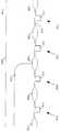
도 1a 내지 1j는 본 발명의 일 실시예에 따른 집적 회로 소자내의 CMOS 트랜지스터 제조를 위한 공정 흐름도이다.1A-1J are process flow diagrams for fabricating CMOS transistors in an integrated circuit device according to an embodiment of the invention.
도 1a 내지 1j는 비대칭 LDD 구조를 채용한 CMOS 트랜지스터를 제조하는 방법의 일 실시예를 설명한 것이다. 도 1a에서, 실리콘 웨이퍼(100)에서 2개의 N-채널 트랜지스터(110 및 130)와 2개의 P-채널 트랜지스터(150 및 170)가 P-웰 기술을 이용하여 구현된다. 이 실시예의 방법은 또한 N-웰 또는 트윈-터브(twin-tub) 기술을 채용한 집적 회로 소자에 적용할 수 있다. 시작 물질은 실리콘 웨이퍼(100)이다. 통상적으로, 실리콘 웨이퍼(100)는 약간 도프된 <100> 웨이퍼 또는 상당히 도프된 <100> 웨이퍼이며, 표면에 약간 도프된 에피텍셜층을 갖는다. P-채널 트랜지스터(150 및 170)는 다소 상당히 도프된 N-웰 구조로서 N-웰 또는 트윈-터브 기술을 이용하여 통상적인 방식으로 형성되는 N-도프된 기판(154)에 형성된다. P-웰 기술을 이용하여 채용된 N-도프된 기판은 약간 도프된 N-기판이다. 마찬가지로 N-채널 트랜지스터(110 및 130)는 약간 도프된 P-기판 또는 더욱 상당히 도프된 P-웰 구조의 어느 하나로서 통상적인 방식으로 형성되는 P-도프된 기판(114)에 형성된다. 웰 구조는 통상적인 방식으로 열 산화물층을 성장시키고, CVD 질화물 막을 증착시키며, 일반적으로 실리콘 표면을 보호하지만 웰 영역을 노출시키는 마스크를 적용하며, 그리고 웰 영역내로 이온을 주입함으로써 형성된다. 웰 이온은 고온 사이클링에 의해 실리콘내로 드라이브됨과 동시에, 산화물층은 웰 영역내에 생성된다. VT드레시홀드-조정 주입이 적용된다. 실리콘 웨이퍼(100)의 표면이 산화물 및 질화물/산화물층으로부터 제거되고, 고립 구조(isolation structure)를 형성하는 새로운 패드-산화물/질화물층이 형성된다. 마스크가 패드-산화물/질화물층을 패턴잉하는데 적용되어, N-도프된 기판 영역(154) 및 P-도프된 기판 영역(114)을 포함하는 활성 소자 영역을 한정하고, 필드 영역을 한정한다. 이어서, 필드 산화물 활성 소자 영역을 고립시키기 위해 영역(106)과 같은 필드 산화물 영역을 형성하도록 필드 산화물이 성장된다. 그 다음, 질화물/산화물층이 활성 소자 영역으로부터 제거된다. 게이트 산화물(102)이 실리콘 웨이퍼(100)의 표면에 오버레이 하도록 성장된다. 폴리실리콘 게이트층은 화학기상증착(CVD) 방식에 의해 증착되고, 폴리실리콘을 게이트 구조(112, 132, 152 및 172)내로 패턴닝하기위해 마스크가 적용된다.Figures 1A-1J illustrate one embodiment of a method of fabricating a CMOS transistor employing an asymmetric LDD structure. In FIG. 1A, two N-
도 1a는 게이트 구조의 형성 후, 그러나 소오스, 드레인 및 LDD 이온 주입전의 실리콘 웨이퍼(100)를 도시한 것이다. 각 N-채널 트랜지스터(110 및 130)의 폴리실리콘 게이트(112 및 132)가 P-도프된 기판(114)의 영역을 오버레이 하도록 형성된다. 각 N-채널 트랜지스터(110 및 130)의 폴리실리콘 게이트(112 및 132)가 P-도프된 기판(114)의 영역을 오버레이 하도록 형성된다. 각 P-채널 트랜지스터(150 및 170)의 폴리실리콘 게이트(152 및 172)가 N-도프된 기판(154)의 영역을 오버레이 하도록 형성된다. 각 P-채널 트랜지스터(150 및 170)의 폴리실리콘 게이트(152 및 172)가 N-도프된 기판(154)의 영역을 오버레이 하도록 형성된다. 게이트 구조를 형성하는 단계를 포함하는 모든 CMOS 제조공정 단계는 통상적인 CMOS 제조 단계이다.Figure 1A shows a
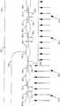
도 1b에 도시된 제 1 마스킹 단계 및 제 1 이온 주입 단계에서, N-LDD 포토레지스트 마스크(190)가 적용되고, N-이온이 통상적인 대칭 LDD 구조 N-채널 트랜지스터인 N-채널 트랜지스터(110)의 N-채널 트랜지스터 LDD 영역(116 및 118)을 형성하도록 주입된다. LDD 영역(116 및 118)에는 폴리실리콘 게이트(112)가 자기-정합된다. 또한, 제 1 마스킹 단계 및 제 1 이온 주입 단계에서, N-이온이 N-채널 트랜지스터(130)의 N-채널 트랜지스터 LDD 영역(136)을 형성하도록 주입된다. 완성시, N-채널 트랜지스터(130)는 비대칭 LDD 구조를 갖는다. 비대칭 LDD 구조는 또한 드레인 영역만이 약간 도프되므로 소위 "진"(true)의 약간 도프된 드레인 구조라 칭한다. N-채널 소오스 영역에 대해 약간의 도프가 가해지지 않는다. N-LDD 포토레지스트 마스크(190)는 P-채널 트랜지스터의 모든 영역을 덮고, 진-LDD P-채널 트랜지스터의 소오스 영역을 덮도록 패턴잉된다. N-채널 LDD 트랜지스터의 드레인 영역은 통상적인 N-채널 LDD 트랜지스터의 소오스 영역처럼 노출되어 있다. N-LDD 포토레지스트 마스크(190)는 예를 들어 대략 0.4μ게이트 길이를 가진 트랜지스터에 대해 0.15μ의 오차내에서 진-LDD 트랜지스터의 게이트 마스크와 정밀하게 정합된다. 이런 정합의 정확성은 상업적으로 이용 가능한 스테퍼(stepper) 시스템에 의해 충족된다.In the first masking step and the first ion implantation step shown in FIG. 1B, an N-
N-LDD 포토레지스트 마스크(190)를 적용하는 단계는 또한 P-채널 트랜지스터 영역에서 N-이온 주입을 방지하기위해 통상적인 LDD 공정에서 수행된다. 그러나, 이 단계는 N-채널 트랜지스터 소오스 영역을 덮고 그리고 N-이온이 주입되지 않는다는 점에서 통상적인 단계와 차이가 있다. 이 차이는 단지 포토레지스트 마스크의 패턴의 변경에 의해 달성되며, 부가적인 마스킹 및 주입 단계에 의해서는 달성되지 않는다.The step of applying the N-
통상적으로, 인 또는 비소 N-형 이온은 N-LDD 주입 단계에서 주입된다. 트랜지스터의 수명동안 핫-캐리어 발생을 줄이도록 약간 도프된 드레인 접합부가 형성된다.Typically, phosphorous or arsenic N-type ions are implanted in the N-LDD implant step. A slightly doped drain junction is formed to reduce hot-carrier generation during the lifetime of the transistor.
N-LDD 포토레지스트 마스크(190)가 제거되고, 도 1c에 도시된 제 2 마스킹 단계 및 제 2 이온 주입 단계에서, N+ 소오스-전용 포토레지스트 마스크(192)가 적용되며, N+이온이 진-LDD N-채널 트랜지스터(130)의 소오스 영역(138)을 형성하도록 주입된다. 소오스 영역(138)은 폴리실리콘 게이트(132)와 자기-정합된다. N+ 소오스-전용 포토레지스트 마스크(192)는 P-채널 트랜지스터의 모든 영역, 즉 통상적인 대칭 LDD 구조 N-채널 트랜지스터의 모든 영역을 덮고, 진-LDD N-채널 트랜지스터의 드레인 영역을 덮도록 패턴잉된다. N-채널 LD 트랜지스터의 소오스 영역만이 노출된다. 마스크(190)와 같이, N+ 소오스-전용 LDD 포토레지스트 마스크(192)는 진-LDD 트랜지스터의 게이트 마스크와 정밀하게 정합된다. 그러나, N+ 소오스-전용 LDD 포토레지스트 마스크(192)는 드레인 영역이 아닌 트랜지스터 소오스 영역을 노출시킨다. N+ 소오스-전용 포토레지스트 마스크(192) 및 N+ 이온 주입을 적용하는 것은 통상적인 CMOS LDD 공정에서 수행되지 않는 부가적인 공정 단계이다. 일반적으로, 비소 N-형 이온이 N+ 소오스-전용 주입 단계에서 주입된다.The N-
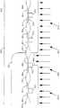
마찬가지로, N+ 소오스-전용 LDD 포토레지스트 마스크(192)가 제거된다. 도 1d에 도시된 제 3 마스킹 단계 및 제 3 이온 주입 단계에서, P-LDD 포토레지스트 마스크(194)가 적용되고, P-이온이 통상적인 대칭 LDD 구조 P-채널 트랜지스터인 P-채널 트랜지스터(170)의 P-채널 트랜지스터 LDD 영역(176 및 178)을 형성하도록 주입된다. LDD 영역(176 및 178)은 폴리실리콘 게이트(172)와 자기-정합된다. 마찬가지로, 이 주입 단계 동안 P-이온이 P-채널 트랜지스터(150)의 P-채널 트랜지스터 LDD 영역(156)을 형성하도록 주입된다. P-채널 트랜지스터(150)는 비대칭 또는 진LDD 구조를 형성하도록 구성된다. P-LDD 포토레지스트 마스크(194)는 N-채널 트랜지스터의 모든 영역을 덮고, 진-LDD P-채널 트랜지스터의 소오스 영역을 덮도록 패턴잉된다. P-채널 LDD 트랜지스터의 드레인 영역은 통상적인 P-채널 LDD 트랜지스터의 소오스 영역처럼 노출된다. P-LDD 포토레지스트 마스크(194)는 진-LDD 트랜지스터의 게이트 마스크와 정밀하게 정합된다. P-LDD 포토레지스트 마스크(194)를 적용하는 단계는 또한 공정에 있어 N-채널 트랜지스터 영역에 P-이온이 주입되는 것을 방지하기 위해 통상적인 LDD 공정에서 수행되는데, 여기에서 통상적인 단계와 단지 차이가 나는 것은 P-채널 트랜지스터 소오스 영역이 P-이온의 주입으로부터 보호되며, 포토레지스트 마스크 패턴에서의 변경만 있을 뿐 부가적인 마스킹 또는 주입 단계가 없다는 점이다. 통상적으로, 붕소 또는 BF2P-형 이온은 P-LDD 주입 단계에서 주입된다.Likewise, the N + source-only
P-LDD 포토레지스트 마스크(194)가 제거되고, 도 1e에 도시된 제 4 마스킹 단계 및 제 4 이온 주입 단계가 수행된다. P+ 소오스-전용 포토레지스트 마스크(196)가 사용되고, P+ 이온이 진-LDD P-채널 트랜지스터(150)의 소오스 영역(158)을 형성하도록 주입된다. 소오스 영역(158)은 폴리실리콘 게이트(152)와 자기-정합된다. P+ 소오스-전용 포토레지스트 마스크(196)는 N-채널 트랜지스터의 모든 영역 즉, 통상적인 대칭 LDD 구조의 P-채널 트랜지스터의 모든 영역을 덮고, 진-LDD P-채널 트랜지스터의 드레인 영역을 덮는다. P-채널 LDD 트랜지스터의 소오스 영역만이 노출된다. P+ 소오스-전용 LDD 포토레지스트 마스크(196)는 진-LDD P-채널 트랜지스터의 게이트 마스크와 정밀하게 정합된다. 그러나, P+ 소오스-전용 LDD 포토레지스트 마스크(196)는 드레인 영역이 아닌 트랜지스터 소오스 영역을 노출시킨다. P+ 소오스-전용 포토레지스트 마스크(196) 적용 및 P+ 이온 주입은 통상적인 CMOS LDD 공정에 부가적인 공정 단계이다. 일반적으로, 붕소 또는 BF2P-형 이온이 P+ 소오스-전용 주입 단계에서 주입된다.The P-
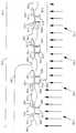
P+ 소오스-전용 포토레지스트 마스크(196)가 제거되고, 도 1f에 도시된 스페이서 산화물층(104)이 실리콘 웨이퍼(100), 폴리실리콘 게이트(112),(132),(152) 및 (172)와 오버레이 하도록 증착된다. 스페이서 산화물층(104)의 적당한 두께는 대략 1000Å 내지 2000Å의 범위이다. 폴리실리콘 게이트(112),(132),(152) 및 (172)의 측부에 인접하여, 대략 게이트의 두께만큼 증가되는 두께로 스페이서 산화물이 증착된다. 도 1g를 참조하면, 스페이서 산화물층(104)은 폴리실리콘 게이트(112)의 측면의 스페이서(120), 게이트(132)의 측면의 스페이서(140), 게이트(152)의 측면의 스페이서(160) 및, 게이트(172)의 측면의 스페이서(180)를 형성하도록 에칭된다. 스페이서를 형성하기위해, 이방성 드라이(anisotropic dry)에칭 공정이 일반적으로 사용되는데, 이는 제어되는 이방성 에칭을 이용하여 양호한 스페이서 형상이 성취되기 때문이다. 스페이서는 게이트 폴리실리콘의 엣지로부터 제거되는 제어된 간격에서 통상의 소오스 및 드레인 주입물을 형성하는 데 이용된다. 이런 스페이싱은 트랜지스터의 직렬 저항을 증가시킨다.The P + source-dedicated
도 1h에 도시된 제 5 마스킹 단계 및 제 5 이온 주입단계에서, N+ 소오스/드레인 포토레지스트 마스크(198)가 적용되고, N+ 이온이 대칭 LDD 구조 N-채널 트랜지스터(110)의 소오스 영역(122) 및 드레인 영역(124)을 형성하도록 주입된다. 소오스 영역(122) 및 드레인 영역(124)은 폴리실리콘 게이트(112) 및 스페이서(120)와 자기-정합된다. 마찬가지로, N+ 소오스/드레인 포토레지스트마스크(198)는 진 LDD N-채널 트랜지스터(130)의 드레인 영역(142)을 형성한다. 드레인 영역(142)은 폴리실리콘 게이트(132) 및 스페이서(140)와 자기-정합된다. N+ 이온 주입물은 일반적으로 비소 이온 주입물이고, AS+ 이온을 주입하기 위한 주입 에너지는 일반적으로 40 kev 내지 80 kev의 범위에 있다.In the fifth masking step and the fifth ion implantation step shown in FIG. 1H, an N + source /
N+ 소오스/드레인 포토레지스트 마스크(198)가 제거되고, 도 1i에 도시된 대응하는 제 6 마스킹 단계 및 제 6 이온 주입 단계에서, P+ 소오스/드레인 포토레지스트 마스크(199)가 적용되고, P+ 이온이 대칭 LDD 구조의 P-채널 트랜지스터(170)의 소오스 영역(182) 및 드레인 영역(184)을 형성하도록 주입된다. 소오스 영역(182) 및 드레인 영역(184)은 폴리실리콘 게이트(172) 및 스페이서(180)와 자기-정합된다. P+ 소오스/드레인 포토레지스트 마스크(199)는 진-LDD P-채널 트랜지스터(150)의 드레인 영역(162)을 형성한다. 드레인 영역(162)은 폴리실리콘 게이트(152) 및 스페이서(160)와 자기-정합된다. BF2+ 이온을 주입하기 위한 주입 에너지는 통상적인 40 kev 내지 80 kev의 범위에 있다.The N + source /
P+ 소오스/드레인 포토레지스트 마스크(199)가 제거됨으로써, 도 1j에 도시된 실리콘 웨이퍼(100)의 최종적인 형상은 통상적인 LDD N-채널 트랜지스터(110),진 LDD N-채널 트랜지스터(130), 진 LDD P-채널 트랜지스터(150) 및 통상적인 LDD P-채널 트랜지스터(170)를 포함한다. 따라서, 예시한 방법은 통상적인 LDD 트랜지스터를 형성하는 통상적인 단계에서 부가적인 2개의 마스킹 및 이온 주입 단계만을 사용하는 CMOS 공정을 이용하여 모두 4개 유형의 LDD 트랜지스터를 제조하는 것을 제시한다. 통상적인 공정과 같이 예시한 공정은 집적 회로 제조 기술에서 공지된 바와 같이 접촉층, 상호 접속부, 불활성화 구조 등을 형성하기 위한 부가적인 표면 처리 동작을 포함한다.The final shape of the
상기 실시예에 대한 설명은 단지 예시를 위한 것이며, 본 발명을 제한하기 위한 것은 아니다. 많은 다른 실시예들이 본 분야의 숙련자에게는 명백해질 것이고, 이들 모두는 본 발명의 넓은 범주내에 포함된다. 본 발명에 따른 장치 및 방법은 CMOS 기술에만 한정되지 않고 NMOS 및 PMOS 기술에도 사용된다. 특히 MOS 기술에 대해, 상기 방법은 P-웰, N-웰 및 트윈-터브 CMOS 기술에 적용할 수 있다.The description of the above embodiments is for illustrative purposes only, and is not intended to limit the present invention. Many other embodiments will be apparent to those skilled in the art, all of which are within the broad scope of the present invention. The apparatus and method according to the present invention are not limited to CMOS technology but are also used in NMOS and PMOS technologies. Especially for MOS technology, the method is applicable to P-well, N-well and twin-tub CMOS technologies.
Claims (9)
Translated fromKoreanApplications Claiming Priority (2)
| Application Number | Priority Date | Filing Date | Title |
|---|---|---|---|
| US08/356,766 | 1994-12-15 | ||
| US08/356,766US5580804A (en) | 1994-12-15 | 1994-12-15 | Method for fabricating true LDD devices in a MOS technology |
Publications (2)
| Publication Number | Publication Date |
|---|---|
| KR980700683A KR980700683A (en) | 1998-03-30 |
| KR100392901B1true KR100392901B1 (en) | 2003-11-20 |
Family
ID=23402876
Family Applications (1)
| Application Number | Title | Priority Date | Filing Date |
|---|---|---|---|
| KR1019970703986AExpired - Fee RelatedKR100392901B1 (en) | 1994-12-15 | 1995-11-22 | Method of manufacturing an asymmetric slightly doped drain (LCD) MOS device |
Country Status (6)
| Country | Link |
|---|---|
| US (1) | US5580804A (en) |
| EP (1) | EP0797841A1 (en) |
| JP (1) | JP4314346B2 (en) |
| KR (1) | KR100392901B1 (en) |
| TW (1) | TW279262B (en) |
| WO (1) | WO1996019010A1 (en) |
Families Citing this family (41)
| Publication number | Priority date | Publication date | Assignee | Title |
|---|---|---|---|---|
| KR100212455B1 (en)* | 1996-11-04 | 1999-08-02 | 정선종 | Process for fabricating semiconductor device with dual gate structure |
| US5900666A (en)* | 1996-12-03 | 1999-05-04 | Advanced Micro Devices, Inc. | Ultra-short transistor fabrication scheme for enhanced reliability |
| US5926714A (en)* | 1996-12-03 | 1999-07-20 | Advanced Micro Devices, Inc. | Detached drain MOSFET |
| US6020232A (en)* | 1996-12-03 | 2000-02-01 | Advanced Micro Devices, Inc. | Process of fabricating transistors having source and drain regions laterally displaced from the transistors gate |
| US5898202A (en)* | 1996-12-03 | 1999-04-27 | Advanced Micro Devices, Inc. | Selective spacer formation for optimized silicon area reduction |
| US5834355A (en)* | 1996-12-31 | 1998-11-10 | Intel Corporation | Method for implanting halo structures using removable spacer |
| US5905210A (en)* | 1997-01-09 | 1999-05-18 | Automotive Systems Laboratory, Inc. | Villari effect seat weight sensor |
| US6039345A (en)* | 1998-01-16 | 2000-03-21 | Automotive Systems Laboratory, Inc. | System and method for sensing vehicle door edge movement |
| JP4527814B2 (en)* | 1997-06-11 | 2010-08-18 | 富士通セミコンダクター株式会社 | Manufacturing method of semiconductor device |
| US5925914A (en)* | 1997-10-06 | 1999-07-20 | Advanced Micro Devices | Asymmetric S/D structure to improve transistor performance by reducing Miller capacitance |
| US6372590B1 (en) | 1997-10-15 | 2002-04-16 | Advanced Micro Devices, Inc. | Method for making transistor having reduced series resistance |
| US5918128A (en)* | 1998-06-08 | 1999-06-29 | Advanced Micro Devices, Inc. | Reduced channel length for a high performance CMOS transistor |
| US6124610A (en) | 1998-06-26 | 2000-09-26 | Advanced Micro Devices, Inc. | Isotropically etching sidewall spacers to be used for both an NMOS source/drain implant and a PMOS LDD implant |
| US6153455A (en)* | 1998-10-13 | 2000-11-28 | Advanced Micro Devices | Method of fabricating ultra shallow junction CMOS transistors with nitride disposable spacer |
| US6362054B1 (en) | 2000-03-13 | 2002-03-26 | Agere Systems Guardian Corp. | Method for fabricating MOS device with halo implanted region |
| WO2001071804A2 (en)* | 2000-03-22 | 2001-09-27 | The Board Of Trustees Of The University Of Illinois | Lateral asymmetric lightly doped drain mosfet |
| US6448121B1 (en)* | 2000-05-31 | 2002-09-10 | Texas Instruments Incorporated | High threshold PMOS transistor in a surface-channel process |
| US7217977B2 (en)* | 2004-04-19 | 2007-05-15 | Hrl Laboratories, Llc | Covert transformation of transistor properties as a circuit protection method |
| US6465307B1 (en)* | 2001-11-30 | 2002-10-15 | Texas Instruments Incorporated | Method for manufacturing an asymmetric I/O transistor |
| DE10224956A1 (en)* | 2002-06-05 | 2004-01-08 | Infineon Technologies Ag | Process for setting the threshold voltage of a field effect transistor, field effect transistor and integrated circuit |
| US7049667B2 (en) | 2002-09-27 | 2006-05-23 | Hrl Laboratories, Llc | Conductive channel pseudo block process and circuit to inhibit reverse engineering |
| WO2004055868A2 (en)* | 2002-12-13 | 2004-07-01 | Hrl Laboratories, Llc | Integrated circuit modification using well implants |
| US6746924B1 (en) | 2003-02-27 | 2004-06-08 | International Business Machines Corporation | Method of forming asymmetric extension mosfet using a drain side spacer |
| US6916716B1 (en)* | 2003-10-24 | 2005-07-12 | Advanced Micro Devices, Inc. | Asymmetric halo implants |
| US7176095B1 (en) | 2004-03-01 | 2007-02-13 | Advanced Micro Devices, Inc. | Bi-modal halo implantation |
| US7064396B2 (en)* | 2004-03-01 | 2006-06-20 | Freescale Semiconductor, Inc. | Integrated circuit with multiple spacer insulating region widths |
| US7242063B1 (en) | 2004-06-29 | 2007-07-10 | Hrl Laboratories, Llc | Symmetric non-intrusive and covert technique to render a transistor permanently non-operable |
| US7144782B1 (en)* | 2004-07-02 | 2006-12-05 | Advanced Micro Devices, Inc. | Simplified masking for asymmetric halo |
| US8168487B2 (en) | 2006-09-28 | 2012-05-01 | Hrl Laboratories, Llc | Programmable connection and isolation of active regions in an integrated circuit using ambiguous features to confuse a reverse engineer |
| US20090090980A1 (en)* | 2007-10-08 | 2009-04-09 | Mingchu King | Asymmetric-ldd mos device |
| US7974119B2 (en) | 2008-07-10 | 2011-07-05 | Seagate Technology Llc | Transmission gate-based spin-transfer torque memory unit |
| US7936580B2 (en) | 2008-10-20 | 2011-05-03 | Seagate Technology Llc | MRAM diode array and access method |
| US9030867B2 (en) | 2008-10-20 | 2015-05-12 | Seagate Technology Llc | Bipolar CMOS select device for resistive sense memory |
| US7936583B2 (en) | 2008-10-30 | 2011-05-03 | Seagate Technology Llc | Variable resistive memory punchthrough access method |
| US7825478B2 (en)* | 2008-11-07 | 2010-11-02 | Seagate Technology Llc | Polarity dependent switch for resistive sense memory |
| US8178864B2 (en) | 2008-11-18 | 2012-05-15 | Seagate Technology Llc | Asymmetric barrier diode |
| US8203869B2 (en) | 2008-12-02 | 2012-06-19 | Seagate Technology Llc | Bit line charge accumulation sensing for resistive changing memory |
| US8159856B2 (en) | 2009-07-07 | 2012-04-17 | Seagate Technology Llc | Bipolar select device for resistive sense memory |
| US8158964B2 (en) | 2009-07-13 | 2012-04-17 | Seagate Technology Llc | Schottky diode switch and memory units containing the same |
| US9000525B2 (en)* | 2010-05-19 | 2015-04-07 | Taiwan Semiconductor Manufacturing Company, Ltd. | Structure and method for alignment marks |
| US8648426B2 (en) | 2010-12-17 | 2014-02-11 | Seagate Technology Llc | Tunneling transistors |
Citations (1)
| Publication number | Priority date | Publication date | Assignee | Title |
|---|---|---|---|---|
| US5349225A (en)* | 1993-04-12 | 1994-09-20 | Texas Instruments Incorporated | Field effect transistor with a lightly doped drain |
Family Cites Families (11)
| Publication number | Priority date | Publication date | Assignee | Title |
|---|---|---|---|---|
| US4318216A (en)* | 1978-11-13 | 1982-03-09 | Rca Corporation | Extended drain self-aligned silicon gate MOSFET |
| JPS60182171A (en)* | 1984-02-29 | 1985-09-17 | Oki Electric Ind Co Ltd | Manufacture of semiconductor device |
| JPH01186676A (en)* | 1988-01-14 | 1989-07-26 | Pioneer Electron Corp | Field effect transistor |
| US4965213A (en)* | 1988-02-01 | 1990-10-23 | Texas Instruments Incorporated | Silicon-on-insulator transistor with body node to source node connection |
| JP2549689B2 (en)* | 1988-02-19 | 1996-10-30 | 三菱電機株式会社 | MOS transistor and manufacturing method thereof |
| US5144390A (en)* | 1988-09-02 | 1992-09-01 | Texas Instruments Incorporated | Silicon-on insulator transistor with internal body node to source node connection |
| US5286664A (en)* | 1991-10-01 | 1994-02-15 | Nec Corporation | Method for fabricating the LDD-MOSFET |
| JPH05129325A (en)* | 1991-10-31 | 1993-05-25 | Sanyo Electric Co Ltd | Semiconductor device |
| JP3221766B2 (en)* | 1993-04-23 | 2001-10-22 | 三菱電機株式会社 | Method for manufacturing field effect transistor |
| US5432366A (en)* | 1993-05-28 | 1995-07-11 | Board Of Regents Of The University Of Texas System | P-I-N MOSFET for ULSI applications |
| US5409853A (en)* | 1994-05-20 | 1995-04-25 | International Business Machines Corporation | Process of making silicided contacts for semiconductor devices |
- 1994
- 1994-12-15USUS08/356,766patent/US5580804A/ennot_activeExpired - Lifetime
- 1995
- 1995-07-29TWTW084107883Apatent/TW279262B/zhnot_activeIP Right Cessation
- 1995-11-22JPJP51887296Apatent/JP4314346B2/ennot_activeExpired - Fee Related
- 1995-11-22KRKR1019970703986Apatent/KR100392901B1/ennot_activeExpired - Fee Related
- 1995-11-22EPEP95940745Apatent/EP0797841A1/ennot_activeWithdrawn
- 1995-11-22WOPCT/US1995/015021patent/WO1996019010A1/ennot_activeApplication Discontinuation
Patent Citations (1)
| Publication number | Priority date | Publication date | Assignee | Title |
|---|---|---|---|---|
| US5349225A (en)* | 1993-04-12 | 1994-09-20 | Texas Instruments Incorporated | Field effect transistor with a lightly doped drain |
Also Published As
| Publication number | Publication date |
|---|---|
| WO1996019010A1 (en) | 1996-06-20 |
| TW279262B (en) | 1996-06-21 |
| JPH10510951A (en) | 1998-10-20 |
| EP0797841A1 (en) | 1997-10-01 |
| KR980700683A (en) | 1998-03-30 |
| US5580804A (en) | 1996-12-03 |
| JP4314346B2 (en) | 2009-08-12 |
Similar Documents
| Publication | Publication Date | Title |
|---|---|---|
| KR100392901B1 (en) | Method of manufacturing an asymmetric slightly doped drain (LCD) MOS device | |
| US5677224A (en) | Method of making asymmetrical N-channel and P-channel devices | |
| KR950001952B1 (en) | Weakly doped drain forming process and MOS integrated circuit fabricated by this process | |
| US5413945A (en) | Blanket N-LDD implantation for sub-micron MOS device manufacturing | |
| US20080242033A1 (en) | Self-Aligned LDMOS Fabrication Method Integrated Deep-Sub-Micron VLSI Process, Using A Self-Aligned Lithography Etches And Implant Process | |
| EP0166167B1 (en) | A process for manufacturing a semiconductor device comprising p-channel and n-channel misfets | |
| US6350639B1 (en) | Simplified graded LDD transistor using controlled polysilicon gate profile | |
| EP0465045B1 (en) | Method of field effect transistor fabrication for integrated circuits | |
| US6207482B1 (en) | Integration method for deep sub-micron dual gate transistor design | |
| US6583013B1 (en) | Method for forming a mixed voltage circuit having complementary devices | |
| US6008100A (en) | Metal-oxide semiconductor field effect transistor device fabrication process | |
| US6287922B1 (en) | Method for fabricating graded LDD transistor using controlled polysilicon gate profile | |
| US6348382B1 (en) | Integration process to increase high voltage breakdown performance | |
| US6162694A (en) | Method of forming a metal gate electrode using replaced polysilicon structure | |
| US6051471A (en) | Method for making asymmetrical N-channel and symmetrical P-channel devices | |
| JP2001085533A (en) | Semiconductor device and manufactue thereof | |
| JPH11284178A (en) | Insulated gate transistor, method of manufacturing the same, and semiconductor integrated circuit device | |
| US7642617B2 (en) | Integrated circuit with depletion mode JFET | |
| US6362034B1 (en) | Method of forming MOSFET gate electrodes having reduced depletion region growth sensitivity to applied electric field | |
| EP1225627B1 (en) | Semiconductor integrated circuit device and manufacture method therefor | |
| JP2000068499A (en) | Semiconductor device and manufacture of the same | |
| KR100415191B1 (en) | Method for fabricating asymmetric cmos transistor | |
| KR100676194B1 (en) | CMOS MOS transistor manufacturing method | |
| JP4068671B2 (en) | Manufacturing method of semiconductor integrated circuit device | |
| KR100311177B1 (en) | A method of fabricating semiconductor device |
Legal Events
| Date | Code | Title | Description |
|---|---|---|---|
| PA0105 | International application | St.27 status event code:A-0-1-A10-A15-nap-PA0105 | |
| R17-X000 | Change to representative recorded | St.27 status event code:A-3-3-R10-R17-oth-X000 | |
| PG1501 | Laying open of application | St.27 status event code:A-1-1-Q10-Q12-nap-PG1501 | |
| A201 | Request for examination | ||
| PA0201 | Request for examination | St.27 status event code:A-1-2-D10-D11-exm-PA0201 | |
| E902 | Notification of reason for refusal | ||
| PE0902 | Notice of grounds for rejection | St.27 status event code:A-1-2-D10-D21-exm-PE0902 | |
| P11-X000 | Amendment of application requested | St.27 status event code:A-2-2-P10-P11-nap-X000 | |
| P13-X000 | Application amended | St.27 status event code:A-2-2-P10-P13-nap-X000 | |
| E701 | Decision to grant or registration of patent right | ||
| PE0701 | Decision of registration | St.27 status event code:A-1-2-D10-D22-exm-PE0701 | |
| GRNT | Written decision to grant | ||
| PR0701 | Registration of establishment | St.27 status event code:A-2-4-F10-F11-exm-PR0701 | |
| PR1002 | Payment of registration fee | St.27 status event code:A-2-2-U10-U12-oth-PR1002 Fee payment year number:1 | |
| PG1601 | Publication of registration | St.27 status event code:A-4-4-Q10-Q13-nap-PG1601 | |
| PR1001 | Payment of annual fee | St.27 status event code:A-4-4-U10-U11-oth-PR1001 Fee payment year number:4 | |
| PR1001 | Payment of annual fee | St.27 status event code:A-4-4-U10-U11-oth-PR1001 Fee payment year number:5 | |
| PR1001 | Payment of annual fee | St.27 status event code:A-4-4-U10-U11-oth-PR1001 Fee payment year number:6 | |
| PR1001 | Payment of annual fee | St.27 status event code:A-4-4-U10-U11-oth-PR1001 Fee payment year number:7 | |
| FPAY | Annual fee payment | Payment date:20100630 Year of fee payment:8 | |
| PR1001 | Payment of annual fee | St.27 status event code:A-4-4-U10-U11-oth-PR1001 Fee payment year number:8 | |
| PN2301 | Change of applicant | St.27 status event code:A-5-5-R10-R11-asn-PN2301 | |
| PN2301 | Change of applicant | St.27 status event code:A-5-5-R10-R11-asn-PN2301 | |
| PN2301 | Change of applicant | St.27 status event code:A-5-5-R10-R14-asn-PN2301 | |
| LAPS | Lapse due to unpaid annual fee | ||
| PC1903 | Unpaid annual fee | St.27 status event code:A-4-4-U10-U13-oth-PC1903 Not in force date:20110716 Payment event data comment text:Termination Category : DEFAULT_OF_REGISTRATION_FEE | |
| PC1903 | Unpaid annual fee | St.27 status event code:N-4-6-H10-H13-oth-PC1903 Ip right cessation event data comment text:Termination Category : DEFAULT_OF_REGISTRATION_FEE Not in force date:20110716 | |
| R18-X000 | Changes to party contact information recorded | St.27 status event code:A-5-5-R10-R18-oth-X000 | |
| P22-X000 | Classification modified | St.27 status event code:A-4-4-P10-P22-nap-X000 |