KR100352660B1 - Liquid distributor for use with containers - Google Patents
Liquid distributor for use with containersDownload PDFInfo
- Publication number
- KR100352660B1 KR100352660B1KR1019970701056AKR19970701056AKR100352660B1KR 100352660 B1KR100352660 B1KR 100352660B1KR 1019970701056 AKR1019970701056 AKR 1019970701056AKR 19970701056 AKR19970701056 AKR 19970701056AKR 100352660 B1KR100352660 B1KR 100352660B1
- Authority
- KR
- South Korea
- Prior art keywords
- bladder
- beverage
- pressure
- container
- suction tube
- Prior art date
- Legal status (The legal status is an assumption and is not a legal conclusion. Google has not performed a legal analysis and makes no representation as to the accuracy of the status listed.)
- Expired - Fee Related
Links
Images


Classifications
- B—PERFORMING OPERATIONS; TRANSPORTING
- B67—OPENING, CLOSING OR CLEANING BOTTLES, JARS OR SIMILAR CONTAINERS; LIQUID HANDLING
- B67D—DISPENSING, DELIVERING OR TRANSFERRING LIQUIDS, NOT OTHERWISE PROVIDED FOR
- B67D1/00—Apparatus or devices for dispensing beverages on draught
- B67D1/04—Apparatus utilising compressed air or other gas acting directly or indirectly on beverages in storage containers
- B67D1/045—Apparatus utilising compressed air or other gas acting directly or indirectly on beverages in storage containers using elastic bags and pistons actuated by air or other gas
Landscapes
- Devices For Dispensing Beverages (AREA)
- Containers And Packaging Bodies Having A Special Means To Remove Contents (AREA)
- Devices For Use In Laboratory Experiments (AREA)
Abstract
Translated fromKoreanDescription
Translated fromKorean현재 판매되는 많은 음료 분배기는 본래 상업적이고 사용하기에 복잡하다. 다른 것들은 음료의 분배 및 그 본래의 질을 유지하는 역할을 하지 못한다.Many drink dispensers currently sold are inherently commercial and complex to use. Others do not play a role in distributing the beverage and maintaining its original quality.
가장 일반적인 장치는 음료를 저장하는 특별한 용기를 필요로 한다. 그러한 용기는 소비자가 추가의 장치를 구매해야 하기 때문에 비실용적이다. 특별한 용기를 사용하게 되면 추가의 저장 공간을 더 필요로 한다. 그것은 또한 소비자가 음료를 그 본래의 용기로부터 특별한 용기로 운반해야 하기 때문에 사용하기가 번거롭다.The most common devices require special containers to store beverages. Such containers are impractical because consumers have to purchase additional devices. The use of special containers requires additional storage space. It is also cumbersome to use because the consumer must transport the beverage from its original container to a special container.
일부 장치는 또한 특별한 용기 내부에 블래더(bladder)를 갖추고 있다. 음료가 소모될 때, 블래더는 용기에 남아있는 음료에 압력을 공급하기 위해 가스와 함께 팽창한다. 이러한 방식으로 탄산이 보존되고 음료는 압력 주입(pouring)에 의해 분배될 수 있다. 다른 장치는 블래더를 이용하지 않고 음료에 직접 가스를 공급함으로서 음료를 압축시킨다. 가스가 공기라면, 음료는 산화되어 음료 맛이 떨어지게 된다. 가스가 이산화탄소라면, 음료는 과도한 탄산을 축적하게 된다. 이로 인해 그 의도된 맛이 변하고 분배될 때 음료에 거품을 야기시킨다. 결국, 음료의 탄산을 유지하거나 압력 주입에 의해 음료를 분배하도록 설계되지 않은 음료 분배기 또는 저장소들이 시판되고 있다.Some devices also have a bladder inside a special container. When the beverage is consumed, the bladder expands with the gas to provide pressure to the beverage remaining in the container. In this way, the carbonic acid is preserved and the beverage can be dispensed by pouring. Other devices compress the beverage by directing the beverage directly into the beverage without using a bladder. If the gas is air, the beverage is oxidized and the beverage taste is reduced. If the gas is carbon dioxide, the beverage will accumulate excess carbonic acid. This causes the beverage to bubble when its intended taste changes and is dispensed. Eventually, beverage dispensers or reservoirs that are not designed to maintain the carbonic acid of the beverage or dispense the beverage by pressure injection are commercially available.
또 다른 장치에서, 본래의 용기 내의 음료에 압력을 공급하기 위해 블래더가 이용된다. 미국 특허 제4,482,072호에 기재된 이러한 장치는 특별한 용기를 이용하지는 않는다. 그러나, 그 장치는 충만된 음료 용기에는 블래더가 끼워맞춰지지 않기 때문에 사용하기에 불편하다. 블래더가 끼워맞춰지기 전에 음료의 일부를 제거되어야 한다. 이것이 정확히 실행되지 않게 되면, 블래더가 용기 안으로 삽입될 때 음료의 일부가 유출되게 된다. 한편, 사용자가 현재 제거된 음료를 소비하지 않게 되면 음료 일부의 제거 동작은 사용자에게 불편을 줄 수 있다. 최종적으로, 탄산도 음료 제거 과정 중에 일부 새어 나오게 된다.In yet another device, a bladder is used to supply pressure to the beverage in the original container. Such devices described in U.S. Patent No. 4,482,072 do not utilize special containers. However, the apparatus is inconvenient to use because the bladder is not fitted to the filled beverage container. A portion of the beverage must be removed before the bladder is fitted. If this is not done correctly, some of the beverage will leak when the bladder is inserted into the container. On the other hand, if the user does not consume the currently removed beverage, the removal operation of the beverage part may inconvenience the user. Finally, the carbonic acid also leaks out during the beverage removal process.
본 발명은 음료 분배기 및 저장소에 관한 것이다.The present invention relates to a beverage dispenser and storage.
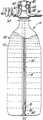
도1은 비팽창 형태의 본 발명을 채용한 음료 용기의 중앙 관통 단면도.BRIEF DESCRIPTION OF THE DRAWINGS Figure 1 is a centrally-passing cross-sectional view of a beverage container employing the present invention in its non-inflated form.
도2는 본 발명에 의해 채용된 하우징의 중앙부의 횡단면도.2 is a cross-sectional view of a central portion of a housing adopted by the present invention;
도3은 본 발명에 의해 채용된 폐쇄 형태의 핀의 상세도.3 is a detailed view of a pin in the closed configuration employed by the present invention;
도4는 도2의 하우징의 횡단면도.Figure 4 is a cross-sectional view of the housing of Figure 2;
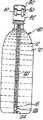
도5a 내지 도5c는 다양한 팽창 형태의 본 발명을 채용한 음료 용기의 중앙 관통 단면도.Figures 5A-5C are cross-sectional, central views of a beverage container employing the present invention in its various inflated forms.
본 발명의 음료 분배 장치는 본래의 음료 용기에 삽입되는 팽창 가능한 블래더를 포함한다. 블래더와 함께, 흡입 튜브는 본래의 음료 용기 내에 삽입된다. 블래더와 흡입 튜브는 최소 변위의 음료 수위를 갖는 완전히 충만된 용기 내부에 끼워맞춰진다. 블래더가 팽창할 때, 블래더는 음료에 압력을 공급하여, 음료는 흡입 튜브 위로 밀리게 된다. 블래더는 음료가 점차적으로 소모됨에 따라 계속 팽창한다. 따라서, 블래더는 항상 음료를 압축시킨다. 또한, 블래더는 음료가 가스와 접촉하는 것을 차단한다. 이러한 방식으로, 음료 양이 다 소모된 후 까지 음료의 질을 유지할 수 있다.The beverage dispensing apparatus of the present invention includes an inflatable bladder that is inserted into an original beverage container. Along with the bladder, the suction tube is inserted into the original beverage container. The bladder and suction tube are fitted inside a fully filled container with a minimal displacement of the beverage level. When the bladder is inflated, the bladder supplies pressure to the beverage and the beverage is pushed over the suction tube. The bladder continues to expand as the beverage is gradually consumed. Thus, the bladder always compresses the beverage. In addition, the bladder blocks the beverage from contacting the gas. In this way, the quality of the beverage can be maintained until the beverage quantity is exhausted.
본 발명의 음료 분배 장치는 분배기를 표준 음료 용기의 주둥이에 쉽게 연결시키는 부착 수단을 더 포함한다. 최종적으로, 본 발명의 음료 분배 장치는 블래더를 팽창시키는 가스 흐름용 도관, 및 음료를 흡입 튜브 위로 분배하는 액체 흐름용 도관을 포함한다.The beverage dispensing apparatus of the present invention further includes attachment means for easily connecting the dispenser to the snout of the standard beverage container. Finally, the beverage dispensing apparatus of the present invention includes a conduit for gas flow to inflate the bladder, and a conduit for liquid flow to dispense the beverage over the suction tube.
따라서, 본 발명의 목적은 완전히 충만된 본래 용기로부터 직접 음료를 분배하는 음료 분배 장치를 제공하는 것이다.Accordingly, it is an object of the present invention to provide a beverage dispensing apparatus for dispensing beverages directly from a fully filled original container.
본 발명의 또 다른 목적은 그 본래의 용기에 있던 것과 같이 음료의 질을 유지시키는 것이다.Another object of the present invention is to maintain the quality of the beverage as in its original container.
본 발명의 다른 목적 및 장점은 이하의 설명에 잘 나타나 있다.Other objects and advantages of the invention are apparent from the following description.
이제 도면을 참조로 바람직한 실시예를 상세히 설명하기로 한다. 여러 도면에 나오는 동일한 요소에는 동일한 도면 부호가 부기되었다.The preferred embodiments will now be described in detail with reference to the drawings. The same elements in the various figures have the same reference numerals.
도1은 본 발명의 음료 분배 장치(10)를 채용한 표준 음료 용기(80)를 도시한다. 용기(80)는 음료(70)로 채워져 있다. 바람직한 실시예는 용기(80)용 표준 1리터, 2리터 또는 3리터의 페트(PET) 소다병을 이용한다. 다른 실시예는 다른 표준 용기 또는 특별 용기를 이용할 수 있다. 바람직한 실시예는 또한 음료(70)용 탄산 음료를 이용한다. 그러나, 와인 또는 과일 주스와 같은 다른 음료를 분배할 수 있다. 실제로, 인간이 소비하기 위한 것이 아닌 어떠한 액체라도 이용될 수 있다.1 shows a
하우징(30)은 도2에 도시된 대로 음료 분배 장치(10)를 용기(80)의 주둥이에 연결시킨다. 하우징(30)은 또한 이하에 기재된 대로 그 구성 요소를 서로 연결시킨다.The
패스너(32)는 하우징(30)의 외부 상에서 미끄러진다. 핀(34)은 하우징(30) 내부에 존재한다. 압력 노즐(52)과 음료 배출 노즐(62)은 하우징(30)을 관통한다. 하우징(30) 내부에서, 블래더(12)는 압력 노즐(52)에 부착되고 흡입 튜브(20)는 음료 배출 노즐(62)에 부착된다. 하우징(30) 외부에서, 압력 튜브(50)는 압력 노즐 (52)에 부착되고 음료 배출 튜브(60)는 음료 배출 노즐(62)에 부착된다.The
바람직한 실시예에서, 하우징(30)은 원통형이고 전술된 요소 및 연결을 허용하도록 하는 크기를 갖는다. 다른 실시예에서, 하우징(30)은 존재하지 않거나 다른 형태로 될 수 있다. 다른 실시예에서, 요소는 다른 형태로 부착될 수 있다,In a preferred embodiment, the
패스너(32)는 음료 분배 장치(10)가 용기(80)로의 선택적 부착을 가능하게 한다. 바람직한 실시예에서, 패스너(32)는 하우징(30)에 부착된 너트로 된다. 너트는 용기(80)의 주둥이 상에 제공되는 외부 나사선에 결합되는 내부 나사선을 갖는다. 다른 실시예에서, 패스너(32)는 커플러, 래치, 또는 보통의 스냅-온 장치와 같은 다른 체결 장치로 될 수 있다.The
핀(34)은 압력 노즐(52)을 거쳐 블래더(12) 안으로의 가스 흐름을 제어한다. 핀(34)은 압력 노즐(52)의 덕트를 덮도록 설계된다. 용기(80)로부터 조립체를 연결 또는 분리시키기 위해 패스너(32)를 회전시킬 때, 핀(34)은 압력 노즐(52)의 덕트를 각각 개방 또는 폐쇄하기 위해 이동된다. 핀(34)은 스프링(36)에 의해 작동된다.The
블래더(12)는 그 본래의 비팽창 형태로 용기(80) 안으로 삽입된다. 블래더 (12)는 그 본래의 비팽창 형태로 도1에 도시되고, 도5에서는 다양한 팽창 형태로 도시된다.The
바람직한 실시예에서, 블래더(12)는 그 상부로부터 그 하부로 점차적으로 증가하는 벽 두께를 갖는 팽창 가능한 긴 본체이다. 이러한 설계는 블래더(12)의 상부가 음료(70) 위의 빈 공간에서 점차적으로 팽창 가능하게 한다. 그후에, 음료 (70)가 소비될 때, 블래더(12)의 하부는 점차적으로 팽창을 개시한다.In the preferred embodiment, the
바람직한 실시예에서, 블래더(12)는 라텍스 재질의 고무로 구성된다. 바람직한 재료는 블래더(12)가 팽창하여 여러번 7.73 kg/㎠ 까지 압축될 때 소성 변형을 방지하도록 설계된다. 따라서, 블래더(12)는 측방향으로만 팽창한다. 그것은 또한 블래더(12)가 용기(80)로부터 제거될 때 음료 적하(dripping)를 최소화한다. 바람직한 재료는 또한 최소 변위의 음료 수위를 갖는 음료(70)로 완전히 채워진 용기 (80) 내부에 끼워맞춰지도록 설계된다.In a preferred embodiment, the
도3에 도시된 대로, 흡입 튜브(20)는 상부로 들어가, 중앙을 관통하여 블래더(12)의 하부로 빠져나간다. 블래더(12)는 블래더(12)를 흡입 튜브(20)에 유지시키기 위해 한 개는 상부에 있고 다른 하나는 하부에 있는 2 개의 고무 링(18)을 갖는다.As shown in FIG. 3, the
바람직한 실시예에서, 흡입 튜브(20)는 원통형 본체이다. 그 외경은 비팽창상태에서 블래더(12) 내부에 끼워맞춰질 정도로 작다. 그 내경은 음료(70)가 관통할 수 있도록 하는 크기를 갖는다. 최하단에서, 흡입 튜브(20)는 용기(80)의 기부상에 고정되는 개구(22)를 갖는다.In a preferred embodiment, the
다수의 플랜지(24)는 블래더(12)가 개구(22) 위로 팽창하는 것을 차단하기 위해 흡입 튜브(20)의 최하단에 부착된다. 바람직한 실시예에서, 연장 칼라(26)에 부착되고, 차례로 블래더(12) 및 흡입 튜브(20)의 단부 위에 부착되는 2개의 플랜지(24)가 존재한다.A plurality of
블래더(12), 흡입 튜브(20), 연장 칼라(26), 및 플랜지(24) 모두는 식품과 함께 사용을 위해 미연방 식품 의약국(FDA)에 의해 승인된 재료로 구성된다. 바람직한 재료는 음료를 오염시키거나 음료 맛을 떨어뜨리는 어떠한 독성 물질을 배출하지 않아야 한다. 바람직한 재료는 또한 용이한 세척을 위해 고온에도 견뎌야 한다.Both the
압력 튜브(50)는 블래더(12)를 압력 노즐(52)을 통해 압력 감지 장치와 핸드펌프와 같은 압력원과 공기 압축기 또는 이산화탄소 공급원에 연결시킨다. 압력 튜브(50)는 압력 공급원을 위해 설계된 호스이다. 압력 감지 장치는 음료(70)가 용기 (80)로부터 제거될 때 압력 공급원을 작동시키거나 작동 중지시킨다.The
음료 배출 튜브(60)는 흡입 튜브(20)를 음료 배출 노즐(62)을 통해 음료 분배관에 연결시킨다. 음료 배출 튜브(60)는 또한 음료 도관으로 설계되고 식품과 함께 사용을 위해 미연방 식품 의약국에 의해 승인된 재료로 제작된 호스이다.The
코일식 튜브(64)는 음료 배출 튜브(60)와 음료 분배관 사이에 배치된다. 코일식 튜브(64)는 음료 배출 튜브(60)의 내경 보다 더 작은 내경을 갖는다. 코일식 튜브(64)는 압력 강하를 야기시키고, 거품이나 또 다른 탄산 손실 없이 음료(70)가 꼭지를 통해 서서히 분배 가능하게 한다. 또 다른 실시예에서, 다른 수단에 의해 압력 강하를 실행할 수 있고, 또는 압력 강하를 피할 수 있다.The coiled
바람직한 실시예에서, 본 발명의 음료 분배 장치(10)는 다음과 같이 작동한다. 음료(70)로 완전히 채워진 새로운 표준 음료 용기(80)는 개방된다. 블래더(12)와 흡입 튜브(20)는 용기(80) 안으로 삽입된다. 조립체를 용기(80)의 상부에 연결시키기 위해 패스너(32)를 회전시킬 때, 핀(34)은 압력 노즐(52)의 덕트를 개방시키기 위해 이동한다. 이러한 방식으로, 가스는 압력 공급원으로부터 압력 튜브(50)와 압력 노즐(52)을 거쳐 블래더(12) 안으로 흐르게 된다. 블래더(12)가 팽창될 때, 블래더는 압력을 음료(70)와 용기(80)의 벽에 공급한다. 이러한 방식으로, 음료(80)는 흡입 튜브(20) 위로 압박되어 음료 배출 노즐(62), 음료 배출 튜브(60), 코일식 튜브(64)를 거쳐 음료 분배 꼭지 외부로 공급된다. 용기(80) 내의 음료(70)가 소비될 때, 압력 센서는 더 많은 가스의 요구를 위해 신호를 보낸다. 압력 공급원은 그후 남아있는 음료(70)를 일정 압력 하에서 유지시키기 위해 블래더(12)를 팽창시킨다. 이러한 방식으로, 탄산은 음료(70)가 완전히 소비될 때 까지 유지된다.In a preferred embodiment, the
블래더(12)가 음료(70) 모두를 흡입 튜브(20) 위로 밀어 올리기 때문에, 용기(80) 내의 전체 음료(70)는 분배될 수 있다. 원할 때, 장치(10)를 용기(80)로부터 분리시키기 위해 패스너(32)를 회전시킬 수 있다. 핀(34)은 압력 노즐(34)의 덕트를 폐쇄하기 위해 이동한다. 이제 블래더(12)와 압력 튜브(50)는 세척된다. 음료 분배 장치(10)는 용기(80)로부터 쉽게 제거되고 세척되어 수없이 재사용할 수 있게 된다.Because the
바람직한 실시예에서, 본 발명의 음료 분배 장치는 냉장고 도어에 장착된다. 여러 음료 용기는 냉장고 내부의 특별한 랙에 배치되어 분배기에 평행하게 또는 연속적으로 연결될 수 있다. 다른 실시예에서, 장치는 이 장치를 위해 특별 설계된 소형 냉장고 안에 또는 꼭지 및 배수 트레이 장착을 위해 개조된 표준 소형 냉장고안에 설치될 수 있다. 그러한 장치는 소정 갯수의 음료 용기를 저장한다. 이러한 장치는 종업원의 이용을 위해 자력 분배기로서 사무실 내에 배치된다. 또한, 많은 예비 음료 용기는 소비자가 용기를 자주 교환할 필요가 없도록 연속적으로 결합될 수 있다. 그러나, 본 발명의 음료 분배 장치는 그 기술 분야에 숙련된 자에게 잘 알려진 많은 다른 형태로 작용할 수 있다.In a preferred embodiment, the beverage dispensing apparatus of the present invention is mounted on a refrigerator door. Several beverage containers can be placed in a special rack inside the refrigerator and connected in parallel or continuously to the dispenser. In another embodiment, the device may be installed in a mini-refrigerator specially designed for this device or in a standard mini-refrigerator adapted for mounting faucets and draining trays. Such a device stores a predetermined number of beverage containers. Such a device is placed in the office as a magnetic distributor for use by employees. In addition, many preliminary beverage containers can be continuously joined so that the consumer does not need to frequently change containers. However, the beverage dispensing apparatus of the present invention can act in many different forms well known to those skilled in the art.
따라서, 완전히 채워진 본래 용기로부터 음료를 직접 분배하고 음료를 압축시키고 음료의 본래 질을 유지하기 위해 팽창 가능한 블래더와 흡입 튜브를 채용한 음료 분배 장치가 개시된다. 본 발명의 실시예와 적용예가 도시되고 기재되었지만, 그 기술 분야에 숙련된 자라면 많은 수정이 본 명세서의 발명 개념으로부터 벗어남이 가능함을 알 수 있을 것이다. 따라서, 본 발명은 첨부된 특허 청구 범위의 정신을 제외하고는 제한되지 않는다.Accordingly, a beverage dispensing apparatus is disclosed that employs an inflatable bladder and suction tube to dispense beverage directly from a fully filled original container, compress the beverage, and maintain the original quality of the beverage. While embodiments and applications of the present invention have been shown and described, those skilled in the art will appreciate that many modifications may be made to depart from the inventive concepts herein. Accordingly, the invention is not limited except as by the spirit of the appended claims.
Claims (10)
Translated fromKoreanApplications Claiming Priority (2)
| Application Number | Priority Date | Filing Date | Title |
|---|---|---|---|
| US08/293,055US5499758A (en) | 1994-08-19 | 1994-08-19 | Liquid dispenser for use with containers |
| US08/293,055 | 1994-08-19 |
Publications (2)
| Publication Number | Publication Date |
|---|---|
| KR970705511A KR970705511A (en) | 1997-10-09 |
| KR100352660B1true KR100352660B1 (en) | 2003-08-21 |
Family
ID=23127460
Family Applications (1)
| Application Number | Title | Priority Date | Filing Date |
|---|---|---|---|
| KR1019970701056AExpired - Fee RelatedKR100352660B1 (en) | 1994-08-19 | 1995-08-08 | Liquid distributor for use with containers |
Country Status (11)
| Country | Link |
|---|---|
| US (2) | US5499758A (en) |
| EP (1) | EP0776315B1 (en) |
| JP (1) | JP3613399B2 (en) |
| KR (1) | KR100352660B1 (en) |
| CN (1) | CN1046680C (en) |
| AU (1) | AU688561B2 (en) |
| BR (1) | BR9508994A (en) |
| CA (1) | CA2197879C (en) |
| DE (1) | DE69502290T2 (en) |
| ES (1) | ES2116103T3 (en) |
| WO (1) | WO1996006036A1 (en) |
Families Citing this family (107)
| Publication number | Priority date | Publication date | Assignee | Title |
|---|---|---|---|---|
| US5499758A (en)* | 1994-08-19 | 1996-03-19 | Mccann's Engineering & Manufacturing Co. | Liquid dispenser for use with containers |
| US5983965A (en)* | 1998-08-10 | 1999-11-16 | Patrick; Bryan Allen | Expander for flexible baby bottle liner |
| US6168048B1 (en) | 1998-09-22 | 2001-01-02 | American Air Liquide, Inc. | Methods and systems for distributing liquid chemicals |
| US6751525B1 (en)* | 2000-06-08 | 2004-06-15 | Beverage Works, Inc. | Beverage distribution and dispensing system and method |
| US7004355B1 (en) | 2000-06-08 | 2006-02-28 | Beverage Works, Inc. | Beverage dispensing apparatus having drink supply canister holder |
| US7083071B1 (en) | 2000-06-08 | 2006-08-01 | Beverage Works, Inc. | Drink supply canister for beverage dispensing apparatus |
| US6896159B2 (en) | 2000-06-08 | 2005-05-24 | Beverage Works, Inc. | Beverage dispensing apparatus having fluid director |
| US6799085B1 (en) | 2000-06-08 | 2004-09-28 | Beverage Works, Inc. | Appliance supply distribution, dispensing and use system method |
| US7754025B1 (en) | 2000-06-08 | 2010-07-13 | Beverage Works, Inc. | Dishwasher having a door supply housing which holds dish washing supply for multiple wash cycles |
| US7331944B2 (en)* | 2000-10-23 | 2008-02-19 | Medical Instill Technologies, Inc. | Ophthalmic dispenser and associated method |
| CA2426182C (en) | 2000-10-23 | 2007-03-13 | Py Patent, Inc. | Fluid dispenser having a housing and flexible inner bladder |
| US7752419B1 (en) | 2001-03-22 | 2010-07-06 | Qst Holdings, Llc | Method and system for managing hardware resources to implement system functions using an adaptive computing architecture |
| US7489779B2 (en) | 2001-03-22 | 2009-02-10 | Qstholdings, Llc | Hardware implementation of the secure hash standard |
| US7962716B2 (en) | 2001-03-22 | 2011-06-14 | Qst Holdings, Inc. | Adaptive integrated circuitry with heterogeneous and reconfigurable matrices of diverse and adaptive computational units having fixed, application specific computational elements |
| US7400668B2 (en) | 2001-03-22 | 2008-07-15 | Qst Holdings, Llc | Method and system for implementing a system acquisition function for use with a communication device |
| US20040133745A1 (en) | 2002-10-28 | 2004-07-08 | Quicksilver Technology, Inc. | Adaptable datapath for a digital processing system |
| US6836839B2 (en) | 2001-03-22 | 2004-12-28 | Quicksilver Technology, Inc. | Adaptive integrated circuitry with heterogeneous and reconfigurable matrices of diverse and adaptive computational units having fixed, application specific computational elements |
| US8843928B2 (en) | 2010-01-21 | 2014-09-23 | Qst Holdings, Llc | Method and apparatus for a general-purpose, multiple-core system for implementing stream-based computations |
| US7653710B2 (en) | 2002-06-25 | 2010-01-26 | Qst Holdings, Llc. | Hardware task manager |
| US6577678B2 (en) | 2001-05-08 | 2003-06-10 | Quicksilver Technology | Method and system for reconfigurable channel coding |
| US7798185B2 (en) | 2005-08-01 | 2010-09-21 | Medical Instill Technologies, Inc. | Dispenser and method for storing and dispensing sterile food product |
| US7046635B2 (en) | 2001-11-28 | 2006-05-16 | Quicksilver Technology, Inc. | System for authorizing functionality in adaptable hardware devices |
| US8412915B2 (en) | 2001-11-30 | 2013-04-02 | Altera Corporation | Apparatus, system and method for configuration of adaptive integrated circuitry having heterogeneous computational elements |
| US6986021B2 (en) | 2001-11-30 | 2006-01-10 | Quick Silver Technology, Inc. | Apparatus, method, system and executable module for configuration and operation of adaptive integrated circuitry having fixed, application specific computational elements |
| US7602740B2 (en) | 2001-12-10 | 2009-10-13 | Qst Holdings, Inc. | System for adapting device standards after manufacture |
| US7215701B2 (en) | 2001-12-12 | 2007-05-08 | Sharad Sambhwani | Low I/O bandwidth method and system for implementing detection and identification of scrambling codes |
| US7403981B2 (en) | 2002-01-04 | 2008-07-22 | Quicksilver Technology, Inc. | Apparatus and method for adaptive multimedia reception and transmission in communication environments |
| US20030185690A1 (en)* | 2002-03-28 | 2003-10-02 | Mindi Xu | Systems and methods for transferring and delivering a liquid chemical from a source to an end use station |
| US7493375B2 (en) | 2002-04-29 | 2009-02-17 | Qst Holding, Llc | Storage and delivery of device features |
| US7660984B1 (en) | 2003-05-13 | 2010-02-09 | Quicksilver Technology | Method and system for achieving individualized protected space in an operating system |
| US7328414B1 (en) | 2003-05-13 | 2008-02-05 | Qst Holdings, Llc | Method and system for creating and programming an adaptive computing engine |
| EP1546021B1 (en)* | 2002-08-13 | 2010-10-20 | Medical Instill Technologies, Inc. | Container and valve assembly for storing and dispensing substances, and related method |
| US8108656B2 (en) | 2002-08-29 | 2012-01-31 | Qst Holdings, Llc | Task definition for specifying resource requirements |
| US7937591B1 (en) | 2002-10-25 | 2011-05-03 | Qst Holdings, Llc | Method and system for providing a device which can be adapted on an ongoing basis |
| US7478031B2 (en) | 2002-11-07 | 2009-01-13 | Qst Holdings, Llc | Method, system and program for developing and scheduling adaptive integrated circuity and corresponding control or configuration information |
| US8276135B2 (en) | 2002-11-07 | 2012-09-25 | Qst Holdings Llc | Profiling of software and circuit designs utilizing data operation analyses |
| US6997219B2 (en) | 2003-05-12 | 2006-02-14 | Medical Instill Technologies, Inc. | Dispenser and apparatus and method for filling a dispenser |
| US7609297B2 (en) | 2003-06-25 | 2009-10-27 | Qst Holdings, Inc. | Configurable hardware based digital imaging apparatus |
| US7226231B2 (en) | 2003-07-17 | 2007-06-05 | Medical Instill Technologies, Inc. | Piston-type dispenser with one-way valve for storing and dispensing metered amounts of substances |
| US7264142B2 (en) | 2004-01-27 | 2007-09-04 | Medical Instill Technologies, Inc. | Dispenser having variable-volume storage chamber and depressible one-way valve assembly for dispensing creams and other substances |
| US7367479B2 (en) | 2004-03-11 | 2008-05-06 | Sitz William G | Device to retain carbonation |
| US7451895B2 (en)* | 2004-10-21 | 2008-11-18 | Global Agricultural Technology And Engineering, Llc | Dispensing system |
| US7810677B2 (en)* | 2004-12-04 | 2010-10-12 | Medical Instill Technologies, Inc. | One-way valve and apparatus and method of using the valve |
| EP1817237A4 (en)* | 2004-12-04 | 2016-08-31 | Medical Instill Tech Inc | One-way valve, apparatus and method of using the valve |
| US20060163290A1 (en)* | 2005-01-27 | 2006-07-27 | Vincent Ehret | Volumetric displacement dispenser |
| US7395949B2 (en)* | 2005-01-27 | 2008-07-08 | Vincent Ehret | Volumetric displacement dispenser |
| EP1868917B1 (en)* | 2005-04-13 | 2011-02-09 | Illinois Tool Works Inc. | Canister with a resilient flexible chamber for electrostatic applicators |
| KR101258552B1 (en)* | 2005-04-13 | 2013-05-02 | 일리노이즈 툴 워크스 인코포레이티드 | spray coating applicator system |
| US8833405B2 (en)* | 2005-12-15 | 2014-09-16 | DD Operations Ltd. | Beverage dispensing |
| US20070181602A1 (en)* | 2006-02-07 | 2007-08-09 | Napa Technology, Llc | Method and apparatus for liquid dispensing head and system |
| US20090004512A1 (en)* | 2006-03-01 | 2009-01-01 | Aquafairy Corporation | Liquid Constant-Rate Emitting Apparatus and Method of Liquid Constant-Rate Emmision |
| US10631558B2 (en) | 2006-03-06 | 2020-04-28 | The Coca-Cola Company | Methods and apparatuses for making compositions comprising an acid and an acid degradable component and/or compositions comprising a plurality of selectable components |
| RU2433947C2 (en)* | 2006-05-26 | 2011-11-20 | Джон Мерлин КОППЛЕСТОУН-БРЮС | Fluid dispenser |
| CN101583542B (en)* | 2006-09-08 | 2013-07-10 | 因斯蒂尔医学技术有限公司 | Apparatus and method for dispensing fluids |
| WO2008098190A1 (en)* | 2007-02-09 | 2008-08-14 | Nathanmed, Llc. | Enteral feeding systems, devices and methods |
| WO2008105001A1 (en)* | 2007-02-26 | 2008-09-04 | Mauro De Mei | Hermetic packaging system of a consumer fluid within a container for the preservation of such consumer fluid from contamination and deterioration during the phases of storage as well as of induction and/or delivery |
| SE533208C2 (en)* | 2007-06-05 | 2010-07-20 | Petainer Lidkoeping Ab | Seal for beverage containers |
| US8162176B2 (en) | 2007-09-06 | 2012-04-24 | The Coca-Cola Company | Method and apparatuses for providing a selectable beverage |
| BRPI0722184A2 (en)* | 2007-11-28 | 2014-08-05 | Winefit S R L | APPLIANCE FOR SERVING WINE OR OTHER LIQUID WHICH CAN BE AFFECTED BY OXYGEN IN BOWL FROM A BOTTLE |
| US8573452B2 (en)* | 2008-02-28 | 2013-11-05 | Stroker Industries, Llc | Trigger activated vented valve system |
| EP2442957A4 (en)* | 2008-06-19 | 2015-06-17 | Romar Engineering Pty Ltd | IMPROVED INJECTION AND / OR ASSAY SYSTEM |
| ITFI20080218A1 (en)* | 2008-11-10 | 2010-05-11 | Alessandro Fineschi | DEVICE AND PROCEDURE FOR PROTECTING AND DISTRIBUTING A GLASS OF WINE OR OTHER DRINKS |
| ITFI20080219A1 (en)* | 2008-11-11 | 2010-05-12 | Enomatic S R L | DEVICE FOR DISPENSING DRINKS FROM CONTAINERS SUCH AS BOTTLES AND THE LIKE. |
| US8646660B2 (en)* | 2009-04-01 | 2014-02-11 | Thomas W. Bates | Reusable beer keg |
| WO2011006212A1 (en)* | 2009-07-16 | 2011-01-20 | Coopers Brewery Limited | Beverage dispensing apparatus |
| US8453888B2 (en)* | 2009-12-10 | 2013-06-04 | Wine Gadgets, Llc | Wine preservation and dispensing apparatus |
| AU2011249932B2 (en) | 2010-05-07 | 2015-12-17 | Alps, Llc | Dispensing machine valve and method |
| EP2447207A1 (en) | 2010-10-29 | 2012-05-02 | AB InBev NV | Dispensing appliance provided with means for positionning a container |
| EP2447208A1 (en) | 2010-10-29 | 2012-05-02 | AB InBev NV | Dispensing appliance provided with a hinged hood |
| US9534831B2 (en)* | 2010-10-29 | 2017-01-03 | Whirlpool Corporation | Liquid dispenser with collapsible container |
| EP2447205A1 (en) | 2010-10-29 | 2012-05-02 | AB InBev NV | Dispensing appliance provided with a removable dispensing cartridge |
| EP2452914A1 (en) | 2010-11-10 | 2012-05-16 | AB InBev NV | Liquid dispensing appliance provided with an anti-drip valve system |
| DE102011100560B3 (en)* | 2011-05-05 | 2012-03-15 | Leibinger Smb Technik Gmbh | Device for filling a container with a liquid intended for consumption |
| US8985404B2 (en)* | 2011-08-29 | 2015-03-24 | Nick Moezidis | Liquid dispensing head forcibly detachable from bottle or container |
| US12264056B2 (en) | 2011-09-02 | 2025-04-01 | Versabev, Inc. | System and method for storing and selectively dispensing liquids |
| US10870565B2 (en) | 2011-09-02 | 2020-12-22 | Bevolution Systems, Llc | Scalable modular system and method for storing, preserving, managing, and selectively dispensing beverages |
| US20130056504A1 (en)* | 2011-09-02 | 2013-03-07 | Ottocom, Llc | System and Method for Interfacing with, and Controlling, Beverage Dispensing Containers |
| EP2757924B1 (en)* | 2011-09-24 | 2016-12-28 | EnE Holdings Ltd | Beverage system with aeration |
| WO2013074782A1 (en)* | 2011-11-15 | 2013-05-23 | Jett Innovation, Llc | Apparatus and method for displacing air from wine containers |
| US9340403B2 (en)* | 2012-04-24 | 2016-05-17 | Geoff Daly | System and method of manual control of gasses used for spoilage retardation and dispensing of perishable potable liquids such as wine |
| US9181021B2 (en)* | 2012-04-26 | 2015-11-10 | Jeffrey J. Manera | Preservation and dispensing system for corked bottles |
| BR102012021408B1 (en)* | 2012-08-24 | 2020-09-29 | Gustavo Foresti Fezer | PACKAGING FOR FILLING AND SPRAYING OF DRINKED BEVERAGES |
| CN102849309A (en)* | 2012-08-30 | 2013-01-02 | 谭晓婧 | Automatic drinking water bag for bicycle |
| DE102012021775B4 (en) | 2012-11-06 | 2014-08-21 | Leibinger Gmbh | Device for filling or emptying a container |
| US9896324B2 (en)* | 2013-01-22 | 2018-02-20 | Timothy W. Dziuk | Apparatus and method for displacing air from wine containers |
| ITGE20130010A1 (en)* | 2013-01-24 | 2014-07-25 | Enosis Srl | DEVICE FOR PROTECTING A LIQUID FROM OXIDATION |
| US9452875B2 (en) | 2013-03-01 | 2016-09-27 | Stonevale Products, Llc | Closures for sealing or pressurizing partially-filled beverage containers and methods related thereto |
| US10800589B2 (en) | 2013-03-14 | 2020-10-13 | Carlos Fernando Bazoberry | Automatic preservative gas replenishing system |
| AU2014239220B2 (en) | 2013-03-14 | 2017-02-16 | Boston Wine Devices, Llc | System and method for preserving wine and other perishable substances |
| US12214126B2 (en) | 2013-03-14 | 2025-02-04 | Oxfo Corporation | Automatic system for the conservation of gas and other substances |
| US10233068B2 (en) | 2013-03-14 | 2019-03-19 | Boston Wine Devices, Llc | System and method for preserving wine and other perishable substances |
| US9403632B1 (en)* | 2013-06-17 | 2016-08-02 | José Luis Marrero Ramos | Fluid dispenser |
| KR200470695Y1 (en)* | 2013-08-14 | 2014-01-15 | 박국서 | pumping container for air blocking |
| US20150048098A1 (en)* | 2013-08-19 | 2015-02-19 | Wai T. Lam | Beverage dispensing and pressurizer system |
| CN103496513A (en)* | 2013-10-09 | 2014-01-08 | 上海和辉光电有限公司 | Photoresist inner bag |
| EA201791068A1 (en)* | 2014-11-19 | 2017-10-31 | Карлсберг Брюириз А/С | PACKAGED CONTAINER FOR STORAGE DRINK |
| US11027961B2 (en)* | 2014-12-30 | 2021-06-08 | Edward Showalter | Apparatus, systems and methods for dispensing drinks, food, and other liquids |
| USD781144S1 (en) | 2015-07-21 | 2017-03-14 | Carlos Fernando Bazoberry | Bottle topper with support legs |
| US9950917B2 (en) | 2016-03-16 | 2018-04-24 | Brian A. Chapman | Beverage preservation and dispensing device |
| US10882730B2 (en)* | 2018-06-25 | 2021-01-05 | Coravin, Inc. | Method and apparatus for beverage dispensing including container stopper |
| US11161682B2 (en)* | 2019-03-27 | 2021-11-02 | Newco 4 LLC | Device for providing a disposable bag in keg or other container |
| CN111620291A (en)* | 2020-05-11 | 2020-09-04 | 安徽华艺不锈钢容器有限公司 | Portable beer brewing assembly |
| CN111634878A (en)* | 2020-05-12 | 2020-09-08 | 安徽华艺不锈钢容器有限公司 | Beer brewing assembly with inflation valve |
| USD1006192S1 (en)* | 2021-05-11 | 2023-11-28 | Designetics, Inc. | Fluid control device |
| US20220402664A1 (en)* | 2021-06-17 | 2022-12-22 | Anheuser-Busch Inbev Sa/Nv | Dispense Apparatus |
| US20240025619A1 (en)* | 2022-07-21 | 2024-01-25 | John C. Mazza | Beverage bladder system and apparatus |
| WO2024263378A1 (en)* | 2023-06-21 | 2024-12-26 | The Coca-Cola Company | Gas backfilled concentrate container |
Family Cites Families (25)
| Publication number | Priority date | Publication date | Assignee | Title |
|---|---|---|---|---|
| US1977862A (en)* | 1933-06-20 | 1934-10-23 | Harry A Uhler | Extractor |
| US3080093A (en)* | 1959-11-04 | 1963-03-05 | Reynolds Metals Co | Dispensing of gas charged liquids |
| US3233779A (en)* | 1962-03-08 | 1966-02-08 | Cornelius Co | Method and apparatus for dispensing carbonated beverages |
| US3244326A (en)* | 1963-02-27 | 1966-04-05 | Jr Glen C Bull | Apparatus for dispensing fluid material |
| US3294289A (en)* | 1965-01-27 | 1966-12-27 | Schlitz Brewing Co J | Dispensing unit |
| US3300102A (en)* | 1965-03-12 | 1967-01-24 | Budzich Tadeusz | Inflatable bag fluid dispensing device |
| GB1190340A (en)* | 1967-12-15 | 1970-05-06 | Teves Gmbh Alfred | Improvements in or relating to Spot Type Disc Brakes |
| FR1588518A (en)* | 1968-07-05 | 1970-04-17 | ||
| US4120425A (en)* | 1972-09-01 | 1978-10-17 | The Champagne Machine Inc. | Apparatus for dispensing sparkling wines |
| US4142657A (en)* | 1975-03-10 | 1979-03-06 | Wanke Ronald L | Dispensing closure with nonrigid follower |
| US4265374A (en)* | 1979-04-02 | 1981-05-05 | Adam Sebalos | Pressure liquid dispenser |
| AU6478780A (en)* | 1979-11-28 | 1981-06-04 | Ampac Pty. Ltd. | Dispensing device |
| US4470526A (en)* | 1981-08-10 | 1984-09-11 | Jungkeun Cha | Siphon dispensing bottle |
| US4482072A (en)* | 1983-05-12 | 1984-11-13 | Hankins Ronald W | Pressurizing apparatus for partially filled containers |
| EP0276097A3 (en)* | 1987-01-22 | 1989-11-15 | Splicerite Limited | Liquid container |
| US4763818A (en)* | 1987-02-06 | 1988-08-16 | Stefano Alfonso D | Removable hygienic hand pump adapter for dispensing liquids |
| US4984713A (en)* | 1987-03-31 | 1991-01-15 | Chambers Gary C | Carbonated beverage dispenser |
| EP0328598A4 (en)* | 1987-07-22 | 1989-10-27 | John Wentworth Bucknell | Improved beverage dispenser. |
| US5180081A (en)* | 1987-09-10 | 1993-01-19 | Mccann's Engineering & Mfg. Co. | Pouring spout and carbonation retention apparatus |
| US4809884A (en)* | 1987-10-13 | 1989-03-07 | Stackhouse Wells F | Wine steward |
| FR2623488A1 (en)* | 1987-11-20 | 1989-05-26 | Gehant Denis | Methods, devices, stoppers and cabinets for dispensing fluid products contained in containers |
| US4881666A (en)* | 1988-01-19 | 1989-11-21 | Robert Tullman | Variable volume container |
| US5040001A (en)* | 1990-06-27 | 1991-08-13 | Hewlett-Packard Company | Collapsible storage bladder for ink cartridges |
| DE4125584A1 (en)* | 1991-08-02 | 1992-02-06 | Herbert Hesser | Preservation of taste of carbon di:oxide beverages - by device which uses compressed air to drive beverage out of bottle |
| US5499758A (en)* | 1994-08-19 | 1996-03-19 | Mccann's Engineering & Manufacturing Co. | Liquid dispenser for use with containers |
- 1994
- 1994-08-19USUS08/293,055patent/US5499758A/ennot_activeExpired - Fee Related
- 1995
- 1995-08-08AUAU32162/95Apatent/AU688561B2/ennot_activeCeased
- 1995-08-08DEDE69502290Tpatent/DE69502290T2/ennot_activeExpired - Fee Related
- 1995-08-08JPJP50811596Apatent/JP3613399B2/ennot_activeExpired - Fee Related
- 1995-08-08CNCN95195597Apatent/CN1046680C/ennot_activeExpired - Fee Related
- 1995-08-08BRBR9508994Apatent/BR9508994A/ennot_activeIP Right Cessation
- 1995-08-08ESES95928359Tpatent/ES2116103T3/ennot_activeExpired - Lifetime
- 1995-08-08WOPCT/US1995/010071patent/WO1996006036A1/enactiveIP Right Grant
- 1995-08-08KRKR1019970701056Apatent/KR100352660B1/ennot_activeExpired - Fee Related
- 1995-08-08CACA002197879Apatent/CA2197879C/ennot_activeExpired - Fee Related
- 1995-08-08EPEP95928359Apatent/EP0776315B1/ennot_activeExpired - Lifetime
- 1995-12-26USUS08/578,750patent/US5667110A/ennot_activeExpired - Fee Related
Also Published As
| Publication number | Publication date |
|---|---|
| DE69502290T2 (en) | 1998-08-20 |
| EP0776315A1 (en) | 1997-06-04 |
| JP3613399B2 (en) | 2005-01-26 |
| CN1167472A (en) | 1997-12-10 |
| JPH10504510A (en) | 1998-05-06 |
| CA2197879A1 (en) | 1996-02-29 |
| US5499758A (en) | 1996-03-19 |
| AU688561B2 (en) | 1998-03-12 |
| BR9508994A (en) | 1997-11-25 |
| WO1996006036A1 (en) | 1996-02-29 |
| CA2197879C (en) | 2004-10-19 |
| US5667110A (en) | 1997-09-16 |
| KR970705511A (en) | 1997-10-09 |
| ES2116103T3 (en) | 1998-07-01 |
| AU3216295A (en) | 1996-03-14 |
| DE69502290D1 (en) | 1998-06-04 |
| CN1046680C (en) | 1999-11-24 |
| EP0776315B1 (en) | 1998-04-29 |
Similar Documents
| Publication | Publication Date | Title |
|---|---|---|
| KR100352660B1 (en) | Liquid distributor for use with containers | |
| US5096095A (en) | Door beverage dispenser | |
| US4984717A (en) | Refillable pressurized beverage container | |
| US11820637B2 (en) | System and method for storing and selectively dispensing liquids | |
| US5240144A (en) | Beverage dispensing apparatus | |
| US6502725B1 (en) | Beverage dispenser | |
| US3349965A (en) | Chargeable package for liquids | |
| US5251787A (en) | Pressurized container dispenser | |
| US4921135A (en) | Pressurized beverage container dispensing system | |
| CA1145303A (en) | Post-mix beverage dispensing system syrup package, valving system and carbonator therefor | |
| US4356937A (en) | Syrup distribution system | |
| US5848736A (en) | Beverage dispenser | |
| KR101780996B1 (en) | Paper-based beer container and dispensing apparatus therefor | |
| US6648187B1 (en) | Extendable spout for use with ice and water dispensers | |
| EP0377195B1 (en) | Beverage dispensing device | |
| US3434632A (en) | Liquid dispensing apparatus | |
| US20040007589A1 (en) | Device and method for dispensing carbonated beverages | |
| US4362256A (en) | Beverage dispenser | |
| US5848623A (en) | Device for pressurizing an aerated drink contained in an aerated drink container | |
| US4238053A (en) | Device for dispensing chilled liquid | |
| US2104466A (en) | Refrigerating dispenser for beverages | |
| US11332277B2 (en) | Apparatus and method for separation of air from fluids | |
| US609970A (en) | lochmann | |
| EP0195692A2 (en) | Dispensing of beverages | |
| JP2002068379A (en) | Household beverage server |
Legal Events
| Date | Code | Title | Description |
|---|---|---|---|
| PA0105 | International application | St.27 status event code:A-0-1-A10-A15-nap-PA0105 | |
| R17-X000 | Change to representative recorded | St.27 status event code:A-3-3-R10-R17-oth-X000 | |
| PG1501 | Laying open of application | St.27 status event code:A-1-1-Q10-Q12-nap-PG1501 | |
| A201 | Request for examination | ||
| P11-X000 | Amendment of application requested | St.27 status event code:A-2-2-P10-P11-nap-X000 | |
| P13-X000 | Application amended | St.27 status event code:A-2-2-P10-P13-nap-X000 | |
| PA0201 | Request for examination | St.27 status event code:A-1-2-D10-D11-exm-PA0201 | |
| E701 | Decision to grant or registration of patent right | ||
| PE0701 | Decision of registration | St.27 status event code:A-1-2-D10-D22-exm-PE0701 | |
| GRNT | Written decision to grant | ||
| PR0701 | Registration of establishment | St.27 status event code:A-2-4-F10-F11-exm-PR0701 | |
| PR1002 | Payment of registration fee | St.27 status event code:A-2-2-U10-U12-oth-PR1002 Fee payment year number:1 | |
| PG1601 | Publication of registration | St.27 status event code:A-4-4-Q10-Q13-nap-PG1601 | |
| PR1001 | Payment of annual fee | St.27 status event code:A-4-4-U10-U11-oth-PR1001 Fee payment year number:4 | |
| FPAY | Annual fee payment | Payment date:20060824 Year of fee payment:5 | |
| PR1001 | Payment of annual fee | St.27 status event code:A-4-4-U10-U11-oth-PR1001 Fee payment year number:5 | |
| PN2301 | Change of applicant | St.27 status event code:A-5-5-R10-R11-asn-PN2301 | |
| PN2301 | Change of applicant | St.27 status event code:A-5-5-R10-R14-asn-PN2301 | |
| LAPS | Lapse due to unpaid annual fee | ||
| PC1903 | Unpaid annual fee | St.27 status event code:A-4-4-U10-U13-oth-PC1903 Not in force date:20070901 Payment event data comment text:Termination Category : DEFAULT_OF_REGISTRATION_FEE | |
| PC1903 | Unpaid annual fee | St.27 status event code:N-4-6-H10-H13-oth-PC1903 Ip right cessation event data comment text:Termination Category : DEFAULT_OF_REGISTRATION_FEE Not in force date:20070901 |