KR100348504B1 - LED lighting equipment - Google Patents
LED lighting equipmentDownload PDFInfo
- Publication number
- KR100348504B1 KR100348504B1KR1019970061464AKR19970061464AKR100348504B1KR 100348504 B1KR100348504 B1KR 100348504B1KR 1019970061464 AKR1019970061464 AKR 1019970061464AKR 19970061464 AKR19970061464 AKR 19970061464AKR 100348504 B1KR100348504 B1KR 100348504B1
- Authority
- KR
- South Korea
- Prior art keywords
- led
- light
- unit
- polarizing
- irradiation
- Prior art date
- Legal status (The legal status is an assumption and is not a legal conclusion. Google has not performed a legal analysis and makes no representation as to the accuracy of the status listed.)
- Expired - Fee Related
Links
Images


Classifications
- G—PHYSICS
- G01—MEASURING; TESTING
- G01N—INVESTIGATING OR ANALYSING MATERIALS BY DETERMINING THEIR CHEMICAL OR PHYSICAL PROPERTIES
- G01N21/00—Investigating or analysing materials by the use of optical means, i.e. using sub-millimetre waves, infrared, visible or ultraviolet light
- G01N21/84—Systems specially adapted for particular applications
- G01N21/88—Investigating the presence of flaws or contamination
- G01N21/8806—Specially adapted optical and illumination features
- F—MECHANICAL ENGINEERING; LIGHTING; HEATING; WEAPONS; BLASTING
- F21—LIGHTING
- F21V—FUNCTIONAL FEATURES OR DETAILS OF LIGHTING DEVICES OR SYSTEMS THEREOF; STRUCTURAL COMBINATIONS OF LIGHTING DEVICES WITH OTHER ARTICLES, NOT OTHERWISE PROVIDED FOR
- F21V5/00—Refractors for light sources
- F21V5/02—Refractors for light sources of prismatic shape
- F—MECHANICAL ENGINEERING; LIGHTING; HEATING; WEAPONS; BLASTING
- F21—LIGHTING
- F21V—FUNCTIONAL FEATURES OR DETAILS OF LIGHTING DEVICES OR SYSTEMS THEREOF; STRUCTURAL COMBINATIONS OF LIGHTING DEVICES WITH OTHER ARTICLES, NOT OTHERWISE PROVIDED FOR
- F21V5/00—Refractors for light sources
- F21V5/04—Refractors for light sources of lens shape
- F—MECHANICAL ENGINEERING; LIGHTING; HEATING; WEAPONS; BLASTING
- F21—LIGHTING
- F21Y—INDEXING SCHEME ASSOCIATED WITH SUBCLASSES F21K, F21L, F21S and F21V, RELATING TO THE FORM OR THE KIND OF THE LIGHT SOURCES OR OF THE COLOUR OF THE LIGHT EMITTED
- F21Y2115/00—Light-generating elements of semiconductor light sources
- F21Y2115/10—Light-emitting diodes [LED]
- Y—GENERAL TAGGING OF NEW TECHNOLOGICAL DEVELOPMENTS; GENERAL TAGGING OF CROSS-SECTIONAL TECHNOLOGIES SPANNING OVER SEVERAL SECTIONS OF THE IPC; TECHNICAL SUBJECTS COVERED BY FORMER USPC CROSS-REFERENCE ART COLLECTIONS [XRACs] AND DIGESTS
- Y10—TECHNICAL SUBJECTS COVERED BY FORMER USPC
- Y10S—TECHNICAL SUBJECTS COVERED BY FORMER USPC CROSS-REFERENCE ART COLLECTIONS [XRACs] AND DIGESTS
- Y10S362/00—Illumination
- Y10S362/80—Light emitting diode
Landscapes
- Engineering & Computer Science (AREA)
- General Engineering & Computer Science (AREA)
- Physics & Mathematics (AREA)
- Health & Medical Sciences (AREA)
- Life Sciences & Earth Sciences (AREA)
- Chemical & Material Sciences (AREA)
- Analytical Chemistry (AREA)
- Biochemistry (AREA)
- General Health & Medical Sciences (AREA)
- General Physics & Mathematics (AREA)
- Immunology (AREA)
- Pathology (AREA)
- Investigating Materials By The Use Of Optical Means Adapted For Particular Applications (AREA)
- Led Device Packages (AREA)
Abstract
Translated fromKoreanDescription
Translated fromKorean본 발명은 광원에 LED를 채용한 LED 조명기에 관한 것이다. 주된 용도로서는CCD 카메라와 편성되어 외관 검사, 이물 검사와 같은 시각 인식 검사용 조명기이다. 구체적으로는 반도체 제조 장치에 있어서의 리드 굴성 검사, 극성 마크의 방향 판별, 성형의 결함이나 균열의 판별, 유리나 금속 제품 제조 라인에 있어서의 크기 검사, 탐상(결함) 검사, 기타 전자 부품 관계나 식품, 정제 등 약품의 검사 장치에 사용되는 것이다.The present invention relates to an LED illuminator employing LED as a light source. The main uses are illuminators for visual recognition inspection, such as visual inspection and foreign material inspection, which are combined with a CCD camera. Specifically, lead flexural inspection in semiconductor manufacturing apparatus, direction determination of polarity marks, determination of molding defects and cracks, size inspection in glass or metal product manufacturing lines, flaw inspection (defect) inspection, and other electronic component relationships and foods It is used for the inspection device of medicines such as tablets.
상기 종래의 조명기로서는 형광등이나 할로겐 전구 등의 조명용 광원이 이용된다. 상기 광원은 일반적으로 발열이 크고, 진동에 약하며, 전력량이 크다는 문제점이 있고, 이것을 조사용 광원으로서 사용하는 조사기는 램프가 나감에 따라 교환 작업을 필요로 하는 것 외에도, 조명 구조가 커지며, 전압 변동에 따른 광량 변화가 커서 실용성이 충분하지 않다는 등의 결점이 있었다.As said conventional illuminator, illumination light sources, such as a fluorescent lamp and a halogen bulb, are used. The light source generally has a problem of high heat generation, weak vibration, and large amount of electric power. In addition, the irradiator using the light source as an irradiation light source requires a replacement operation as the lamp goes out, and the illumination structure becomes large, and the voltage fluctuations. There is a drawback that the change in the amount of light is large, so that the practicality is not sufficient.
상기 문제점을 해결하기 위해서, 종래의 광원에서 LED 광원을 사용한 조명기로 변경이 모색되고 있다.In order to solve the above problem, the change from the conventional light source to the illuminator using the LED light source has been sought.
그런데, LED는 광량이 적기 때문에 이것을 보충하는 연구가 필요하다. 그 연구로서, 사용 LED 개수를 늘리는 집광형 LED를 사용하거나, 또는 각종 렌즈를 사용하여 조사광을 집광, 확산시켜 외관상의 광원 크기를 크게 하는 등의 수단을 단독으로 또는 조합하여 사용하고 있었다.However, since LEDs have a low amount of light, research to supplement them is necessary. For this study, a condensing type LED that increases the number of LEDs used is used, or means such as condensing and diffusing the irradiation light using various lenses to increase the apparent light source size are used alone or in combination.
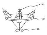
도 4에 도시된 구성은 실용신안출원공개평성6년 제68205호 공보의 구성을 나타내는 것이다. 4개의 스폿 조명기(91, ···)를 중앙 축선 방향으로 비스듬히 조명기 부착판(92)에 장착하여, 중첩된 LED 스폿광(93)을 얻는 구성으로, 스폿 조명기(91)의 각도 보정이 필요하고, 조명기도 큰 것이었다.4 shows the configuration of Utility Model Application Publication No. 6-68 No. 68205. Four spot illuminators (91) are mounted on the illuminator attachment plate at an angle in a central axis direction to obtain superimposed LED spot light (93), and the angle correction of the spot illuminator (91) is necessary. And lighting was great too.
또한, LED는 적색 LED, 황색 LED, 녹색 LED, 청색 LED와 같이 각 색이 단색인 LED가 제공되며, 따라서 조명기에 채용된 경우에 특정색의 조명 광원이 된다. 상기 각 검사용 조명 광원으로서는, 피검출물에 따라서 최적의 조명색과 광량이 있어서, 단색의 LED 조명기로서는 각종 검사기용 광원에 범용적으로 사용할 수 없는 문제점이 있었다. 예를 들면 CCD 카메라로 촬영한 화상을 2치화하여 검사하는 시각 인식을 위해서는 피검사물의 재질에 따라서 높은 명암의 대조를 얻는 것이 검사 정밀도 향상을 위해서는 필수적인 기술적 과제이기 때문이다.In addition, the LEDs are provided with LEDs having a single color, such as red LEDs, yellow LEDs, green LEDs, and blue LEDs, and thus become light sources of a specific color when employed in illuminators. As the illumination light sources for each inspection, there is an optimal illumination color and the amount of light depending on the detected object, and there is a problem that the monochromatic LED illuminator cannot be used universally for various inspection light sources. For example, in order to visually inspect the image captured by a CCD camera by binarization, obtaining high contrast according to the material of an inspection object is an essential technical task for improving inspection accuracy.
덧붙여서 스폿 조명기(91)로부터의 피조사면으로 투영해내는 조사 분포는 각각 다르다. 이것은 LED 자체의 조사 분포가 내장된 LED 칩이나 해당 LED 칩을 둘러싼 수지 주형등의 형상에 의해서 좌우되며, 각 색, 또는 같은 종류라도, 차이가 있으면 그것이 조사 분포상에 있어서 조사 면적이나 조도의 불균일함 등에 영향을 주기 때문이다. 또한 LED의 구조상, 내장된 LED 칩의 상이 피조사면 상에서 결상(結像)되는 등, 얻어지는 조도에는 불균일함이 있고, 균일성이 없었다. 이러한 점에서 LED 광을 그대로 집광하여 스폿을 얻더라도, 각 LED에 따라서 스폿광의 조사 분포에 격차가 있었다.Incidentally, the irradiation distribution projected onto the irradiated surface from the
상기로부터, 상술된 선행 기술에서는 중첩된 LED 스폿광(93)에는 조사의 불균일함이라든지 중합되지 않는 여분의 조사광이 존재하는 등, 높은 명암의 대조가 얻어지지 않는, 시각 인식성에 선명함이 결여된 것이었다.From the above, in the above-described prior art, the superimposed
본 발명의 목적은 LED 광원(발광 다이오드 광원)을 이용한 LED 조명기를 구성함에 있어서, 간단한 구성이면서 조명 불균일함이 없는 밝은 LED 조명기를 제공하는데 있다.SUMMARY OF THE INVENTION An object of the present invention is to provide a bright LED illuminator that is simple in construction and without illumination unevenness in constructing an LED illuminator using an LED light source (light emitting diode light source).
또한, 임의의 조명색을 얻는 LED 조명기를 제공하여, 각종 검사기용 광원에 범용적으로 사용할 수 있는 LED 조명기를 제공하는데 있다.In addition, it is to provide an LED illuminator that obtains an arbitrary illumination color, to provide an LED illuminator that can be used universally for various light sources for inspection.
본 발명의 목적을 달성하기 위한 청구범위 제1항의 LED 조사기는 다수의 LED 소자가 소정의 배열 상태로 장착된 LED부와, 상기 다수의 LED 소자와 대향 배치된 편광 광학계부와, 이들 보유수단을 구비하여, 소정의 촛점거리에서, LED 조사광이 중합되도록 구성된 것을 특징으로 한다.The LED illuminator of
청구범위 제2항의 발명에서는 다수의 LED 소자가 소정의 배열 상태로 장착된 LED부와, 상기 다수의 LED 소자와 대향 배치된 집광 광학계부 및 편광 광학계부와, 이들 보유수단을 구비하여, 소정의 촛점거리에서 LED 조사광이 중합되도록 구성된 것을 특징으로 한다.In the invention according to claim 2, a plurality of LED elements are mounted in a predetermined arrangement, a condensing optical part and a polarizing optical part arranged opposite to the plurality of LED elements, and these holding means are provided. Characterized in that the LED irradiation light is polymerized at the focal length.
청구범위 제 3 항의 발명에서는 다수의 LED 소자가 소정의 배열 상태로 장착된 LED부와, 상기 다수의 LED 소자와 대향 배치된 확산 광학계부, 차광부, 집광 광학계부 및 편광 광학계부와, 이들의 보유수단을 구비하여, 소정의 촛점거리에서 LED 조사광이 중합되도록 구성된 것을 특징으로 한다.According to the invention of
또한, 청구범위 제 4 항의 발명은 광원측에 설치한 제 1 편광면과, 피조명면측에 설치한 제 2 평광면을 갖는 굴절하는 편광 프리즘으로 편광 광학계부를 구성한 것이며, 청구범위 제 5 항의 발명은 다수색의 LED 소자를 조합하여 사용하는 동시에 각 개별, 또는 색군마다 LED 소자의 광량을 조정하는 제어수단을 구비하는 것을 각각 특징으로 한다.The invention according to claim 4 comprises a polarizing optical system part comprising a refracting polarizing prism having a first polarizing surface provided on the light source side and a second flat surface provided on the illuminated surface side, and the invention according to
도 1은 본 발명에 따른 일 실시예의 LED 조명기 주요부 단면도.1 is a cross-sectional view of an essential part of an LED illuminator of an embodiment according to the present invention;
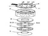
도 2는 LED 조명기의 분해 사시도.2 is an exploded perspective view of an LED illuminator;
도 3은 LED 조명기의 회로도.3 is a circuit diagram of an LED illuminator.
도 4는 종래의 LED 조명기의 사시도.4 is a perspective view of a conventional LED illuminator.
* 도면의 주요 부분에 대한 부호의 설명 *Explanation of symbols on the main parts of the drawings
1: LED 11: 적색 LED1: LED 11: red LED
12: 청색 LED 13: 녹색 LED12: Blue LED 13: Green LED
2: 하우징 3: LED 기판2: housing 3: LED board
4: CCD 카메라 5: 굴절하는 편광 프리즘4: CCD camera 5: polarizing prism refracting
51: 제 1 편광면 52: 제 2 편광면51: first polarization plane 52: second polarization plane
6: 집광 렌즈 63: 차광실6: condensing lens 63: shading chamber
7: 피검사물 8: 확산 필름7: Test object 8: Diffusion film
본 발명의 실시 형태를 도면에 기재된 실시예에 근거하여 설명한다. 도 1은 본 발명에 따른 LED 조명기의 주요부 단면도이며, 도 2는 주요부 분해 사시도이고, 도 3은 회로도를 나타낸다.Embodiment of this invention is described based on the Example described in drawing. 1 is a cross-sectional view of an essential part of an LED illuminator according to the present invention, FIG. 2 is an exploded perspective view of an essential part, and FIG. 3 shows a circuit diagram.
1은 조명광원의 LED 소자이다. 실시예에서는 수지성형된 LED에 리드 프레임 다리부를 구비한 LED 램프이고, LED 기판(3)에 납땜하여 LED부로 하고, 급전회로(給電回路)에 편성되어 있다. LED 소자(1)는 적색, 청색, 녹색으로 각 색이 있고, 그 배치는 도 2에 도시된다. 도 2에서 LED 기판(3) 상부로부터 시계 방향로 청색 LED(12), 녹색 LED(13), 적색 LED(11), 녹색 LED(13), 청색 LED(12), 녹색 LED(13), 적색 LED(11), 녹색 LED(13)로 각 색의 LED가 원주상에 균등하게 설치되어 있다. 녹색 LED(13)의 개수가 많은 이유는 적색, 청색의 LED와 비교하여 휘도가 낮기 때문이다. 각각의 LED광은 중합되어, 광 색이 백색이 된다.1 is an LED element of an illumination light source. In the embodiment, the resin-molded LED is an LED lamp having a lead frame leg. The LED lamp is soldered to the
LED(1)는 집광형의 LED로, 투광의 확산 각도는 10도 전후이다. 후술되는 촛점 거리를 조정하기 위해서는 확산 각도를 적절히 조정하여 집광하면 된다. 원판상의 기판(3)에는 중앙 구멍부가 있어 도우넛 형상이 되며, 하우징(2)의 내통부(21)와 외통부(22) 사이에 끼워 장착된다. 하우징(2)의 내통부(21) 속에는 CCD 카메라(4)가 상방으로부터 삽입되어, 본 발명에 따른 LED 조명기에 조명되는 피검사물(7)을 촬영하도록 구성된다.The
상기 LED부의 다른 구성으로서, LED 광원에 칩형 LED를 채용하여 렌즈와 편성시킨 구성, 또는 집합형 LED 램프 등 다른 LED 광원을 채용하더라도 동일한 작용 효과를 얻는다. 또한 프린트 배선 기판에 의한 LED부 이외에 단체(單
또한, 하우징(2)의 하방으로부터는 중공 원판상의 확산 필름(8), 동일하게 차광실(63)을 부착한 집광렌즈(6) 및 둥근 고리 형상의 굴절하는 편광 프리즘(5)을 내통부(21)와 외통부(22) 사이에 끼워서 장착한다. 확산 필름(8)은 확산성을 갖는 플라스틱 필름과 같은 투광성 재료로 형성되어 있다. 확산 필름(8)의 하방으로부터는 집광렌즈(6)가 설치된다. 집광렌즈(6)는 원판상의 받침대(62)와, 받침대(62)의 하방을 렌즈부(61, ···)가 원주상으로 설치되어, 그것을 일체적으로 형성하고 있다. 차광실(63)은 투과 구멍(64,···)이 원주상에 뚫린 중공 원판상의 부재로, 투과 구멍(64,···)의 각 원 중심은 상기 렌즈부(61)의 각 중심과 각각 동축상에 있다. 차광실(63)은 집광렌즈(6)와의 위치 관계를 갖기 위해서 부착된 것이지만, 다른 구성으로서 집광렌즈(6)의 상부면에 마스킹 처리를 행하는 차광시트로서 렌즈(5)상에 고정하는 방법도 있다. 또한 상술된 확산 필름(8)은 LED(1)가 갖는 한쪽으로 치우친 조사 분포를 균일화하기 위한 것으로, 다른 집광렌즈(6)의 상면에 주름(crimp) 가공과 같은 광 확산 처리를 행하는 것과 같은 방법도 있다.Further, from below the housing 2, a hollow disk-
집광렌즈(6)의 받침대(62) 내주 가장자리 하면에는, 굴절하는 편광 프리즘(5)의 접촉부(53)가 하방으로부터 접촉되어 고착된다. 51은 LED측에 설치된 제 1 편광면이며, 52는 피조명면측에 설치된 제 2 편광면이고, 양면의 프리즘 효과에 의해서, 중앙 축선 방향으로 충분한 편광이 제공될 수 있다.The
상기 굴절하는 편광 프리즘(5)은 투광성 재료로 형성되어 있다. 투광성을 갖는 재료라면 상응되는 작용을 가지며, 메타크릴 수지, AS 수지 등의 투명성이 있는 합성 수지, 유리 등의 무기질이라도 굴절하는 편광 프리즘으로서 사용할 수 있다.The refracting
다음에, 도 1을 참조하여, LED 조사광의 경로를 이하에 설명한다.Next, with reference to FIG. 1, the path | route of LED irradiation light is demonstrated below.
LED(1)의 수지주형에 집광된 LED 조사광은 확산 필름(8)을 투과하여 조도가 균일한 조사광이 되며, 차광실(63)을 거쳐서 집광렌즈(6)에 입사된다. 집광렌즈(6)로의 입사광은 차광실(63)에 의해서, 투과 구멍(64)에 조사되는 광만이 투광된다. 그 이외의 조사광은 차폐되기 때문에, 집광렌즈(6)로 조사되지 않는다. 집광렌즈(6)로의 입사광은 렌즈부(61)에 입사되고, 집광된다. 그대로 조사되면, LED(1)의 수직 하방을 비추게 된다. 이 때 LED(1)의 각 조사 면적은 차광실(63)에 의해서 스폿광만이 되며, 또한 투과 구멍(64)의 면적을 균일하게 함으로써, 각 조사 면적은 동일한 것이 된다.The LED irradiation light focused on the resin mold of the
다음에, 수직 하방을 향한 LED 조사광은 굴절하는 편광 프리즘(5)에 입사된다. 먼저 LED 측에 설치된 제 1 편광면(51)에 의해서, 또한 피조명면측에 설치된 제 2 편광면(52)에 의해서 LED 조명기의 중앙 축선 방향으로 편광되는 것이다.Next, the LED irradiation light directed downward is incident on the refracting
이 때, LED 조명기와 피조명면의 거리를 소정의 촛점거리로 한 경우에, 다수의 LED 조사광이 중합되도록 편광 각도를 설정하여, 피검사물(7)을 LED 조사광이 중합된 조명 아래에 두도록 구성되어 있다.At this time, when the distance between the LED illuminator and the surface to be illuminated is a predetermined focal length, the polarization angle is set so that a large number of the LED irradiation light is polymerized, and the inspected object 7 is placed under the illumination of the LED light irradiation. It is configured to put.
굴절하는 편광 프리즘(5)의 2중 편광 구조는 LED 조명기와 피조명면간의 촛점거리를 짧게 하여, CCD 카메라를 피검사물(7)에 근접시키기는 데 효과적이다. 동시에 이 구조를 채용함으로써 편광 각도가 커지기 때문에, LED 조명기의 둘레 방향 크기도 박형화(薄型化)되는 것이다.The double polarization structure of the refracting
가령, LED측에 설치된 제 1 편광면(51)의 편광 각도를 크게 하면, 1개의 편광면에서도 충분한 각도를 얻을 수 있다. 그런데 프리즘으로의 입사 각도가 작게 되기 때문에 LED 광의 인사 효율이 떨어지고, 또한 하우징(2)의 내통 하측 부분의 벽면에 LED광이 차단된다. 그래서 하우징(2)의 내주 벽면을 투명하게 하면 CCD 카메라로 LED 광의 새어나가는 빛이 입사되는 문제점이 있다.For example, when the polarization angle of the
그래서 실시예에 나타낸 바와 같이 편광면(51)에 있어서 A°, 편광면(52)에 있어서 B°의 편광 각도를 부여하여, 2중 편광 구조로 함으로써 편광 각도가 크고, 촛점 거리가 짧은 화상 인식 검사기용 LED 조명기를 제공할 수 있다.Therefore, as shown in the embodiment, by providing a polarization angle of A ° in the
도 3은 LED 조명기의 회로도이다. 회로는 3계통으로, 적색 LED, 청색 LED, 및 녹색 LED의 회로 부분으로 구성된다. 적색 LED 부분은 적색 LED(11,11)와 병렬로 연결된 전류 제한 저항기, 및 직렬로 연결된 조광용 볼륨(14)과 전류 제한 저항기로 구성된다. 청색 LED 부분은 청색 LED(12,12)와 병렬로 연결된 전류 제한 저항기, 및 직렬로 연결된 조광용 볼륨(14)과 전류 제한 저항기로 구성된다. 녹색 LED 부분은 녹색 LED(13,13,13,13)와 병렬로 연결된 전류 제한 저항기, 및 직렬로 연결된 조광용 볼륨(14)과 전류 제한 저항기로 구성된다.3 is a circuit diagram of an LED illuminator. The circuit is composed of three circuits, and is composed of a circuit portion of a red LED, a blue LED, and a green LED. The red LED part consists of a current limiting resistor connected in parallel with the
본 회로에서 LED 군마다 설치된 조광용 볼륨(14)으로 각 색 LED로의 전류를 조정함으로써, 조명 밝기, 색도의 중합 상태를 조정할 수 있다.In this circuit, by adjusting the current to each color LED by the dimming
부가하여, 본원 발명의 주요 구성에 대해 요약하면, 굴절하는 편광 프리즘을사용하여 광을 굴절시키는 원리를 이용한 것으로, LED로부터의 조사광이 중앙축선상을 향해 굴절되도록 굴절하는 편광 프리즘을 배치시켜 구성되어 있으며, 정립한 LED와 중앙 축선의 거리는 어느 쪽도 같으므로 굴절하는 편광 프리즘의 각도를 균일하게 하고 또한, LED와 굴절하는 편광 프리즘의 위치 관계를 동일하게 하면, LED 광은 중앙축선상의 한 점에서 중합하게 되고, 이로 인해 얻어지는 중합광이 피조사면을 조명하게 된다(도 1 참조). LED 광의 집중을 위하여 굴절하는 편광 프리즘을 사용하는 이유에 대하여 요약하면, 본원 발명의 구성에 의하면, 굴절하는 편광 프리즘에 의해 LED광의 조사각도를 조정할 수 있으므로, LED 자체에는 도 4에 도시된 바와 같이 특정 각도로 유지시켜 놓을 필요가 없이(예를 들면, 특정 각도를 부가하여 장착하는 각도의 유기구를 설치할 필요 없이), 정립된 상태로 구성할 수 있으며, 이로 인해 용이한 LED 조명기를 제조할 수 있고, 제조 공정 및 비용 절감을 발생시킬 수 있으며, 또한, 굴절하는 편광 프리즘에 의해 LED광의 집광 위치를 조정함으로써, 피조사면까지의 거리를 단축시켜 매우 짧은 거리에서 영상을 찍을 수 있을 뿐만 아니라, 동시에, LED 조명기의 둘레 방향의 크기도 작아지므로 장치 자체의 소형화를 이룰 수 있으므로, 굴절하는 편광 프리즘을 사용하는 것이다.In addition, the main configuration of the present invention is summarized by using the principle of refracting light using a refracting polarizing prism, which is configured by disposing a polarizing prism refracting so that the irradiation light from the LED is refracted toward the center axis. Since the distance between the established LED and the center axis is the same, if the angle of the refracting polarizing prism is equalized and the positional relationship between the LED and the refracting polarizing prism is the same, the LED light is a point on the center axis. And the polymerization light obtained thereby illuminates the irradiated surface (see FIG. 1). Summarizing the reason for using the polarizing prism refracting for the concentration of the LED light, according to the configuration of the present invention, since the irradiation angle of the LED light can be adjusted by the refracting polarizing prism, the LED itself is as shown in Figure 4 There is no need to keep it at a specific angle (for example, no need to install an organic sphere of the angle to add a specific angle), it can be configured in an upright state, which makes it easy to manufacture an LED illuminator In addition, the manufacturing process and cost reduction can be generated, and by adjusting the condensing position of the LED light by the refracting polarizing prism, the distance to the irradiated surface can be shortened and images can be taken at a very short distance. Since the size of the circumferential direction of the LED illuminator is also reduced, the device itself can be miniaturized. To use.
이상에 본 발명과 관계되는 LED 조명기 실시예의 주요부, LED 광 경로 등의 구성에 대하여 설명하였다. LED 조명기는 조명기 본체와 조광용의 제어 유닛(도시 하지 않음)으로 구성되어, 예를 들면 전자 부품 실장기(電子部品實裝機)의 화상 인식 기구 부분에 편성시켜 사용된다. 카메라 근방에 설치하여 조사된 피검사물을 촬영하는 양태가 통상의 사용 양태이다. 카메라로부터 촬영된 화상이 한번 화상 인식기구 부분에서 해석되면, 그 신호를 제어 유닛이 받아들여 최적의 조사 조건이 되도록 조명 밝기, 색도의 중합 상태를 조정한다. 실시예의 LED 조명기에 의하면, LED부에는 적색, 청색, 녹색의 LED가 적절히 설치되어 있고, 각 색 LED로의 전류를 조정함으로써, 얻어지는 중합광의 조명 밝기, 색도의 조광이 가능하다.The structure of the principal part, LED light path, etc. of the LED illuminator embodiment concerning this invention was demonstrated above. An LED illuminator is comprised by the illuminator main body and the control unit (not shown) for dimming, for example, it is used in combination with the image recognition mechanism part of an electronic component mounting machine. The aspect which photographs the to-be-tested object irradiated by installing in the camera vicinity is a normal use aspect. Once the image captured by the camera is interpreted by the image recognition mechanism part, the control unit receives the signal and adjusts the polymerization state of illumination brightness and chromaticity so as to be an optimal irradiation condition. According to the LED illuminator of the embodiment, red, blue, and green LEDs are appropriately provided in the LED section, and the illumination brightness and chromaticity of the obtained polymerization light can be adjusted by adjusting the current to each color LED.
이에 따라 피검사물의 재질이나 색상에 따라서, 적당한 조명광, 광량을 갖는 중합광을 제공할 수 있으며, 높은 명암의 대조를 얻을 수 있다.Thereby, according to the material and color of an inspection object, the polymerization light which has moderate illumination light and light quantity can be provided, and high contrast contrast can be obtained.
그 외, 피검사물 플레이트의 하면에 LED 조명기를 설치하여 투과광에 의한 사용 등, 편성 검사기, 검사 대상물에 따라서 각종의 사용 양태가 있다.In addition, the LED illuminator is provided on the lower surface of the inspection object plate, and there are various usage modes depending on the knitting inspection device and the inspection object, such as use by transmitted light.
또한, 본 발명의 실시의 형태에 의한 설명 이외에도, 예를 들면, LED의 수지 주형을 이중으로 한 집광렌즈가 부착된 LED 램프를 채용할 수도 있으며, LED를 둘레 방향으로부터 안쪽을 향하여 설치하여 프리즘에 의하여 수직방향으로 편광시키는 구성도 가능하다.In addition to the description according to the embodiment of the present invention, for example, an LED lamp with a condenser lens having a double resin mold of the LED may be employed, and the LED may be installed in the prism with the LED installed inward from the circumferential direction. It is also possible to configure the polarization in the vertical direction.
그 외 LED는 투광의 확산 각도가 10도 전후인 것에 한정되지 않고, 30도나 45도 등도 가능하다.In addition, the LED is not limited to the diffusion angle of light transmission around 10 degrees, it is possible to 30 degrees, 45 degrees and the like.
확산 필름, 차광실과, 실시예의 배치 관계만에 제한되지 않고, 예를 들면 굴절하는 편광 프리즘의 제 1 반사면(51)의 상면으로 광 확산시키는 처리를 시행할 수도 있으며, 집광렌즈의 하면측에 차광 처리를 시행하는 것도 가능하다.The diffusing film, the light shielding chamber, and the arrangement relationship of the embodiment are not limited to. For example, a light diffusing process may be performed on the upper surface of the first reflecting
굴절하는 편광 프리즘은 실시예에서는 일체의 둥근 고리 형상체로서, 원추형 면의 프리즘면이지만 프리즘면은 평면상으로 형성할 수도 있으며, 각 LED에 대응하는 개별 프리즘이라도 가능하다. 채용하는 다수색의 LED는 적색, 황색, 녹색, 오렌지색, 청색 기타 각 색의 LED를 2종류 이상 적절히 조합함으로써 사용하는 검사기에 최적의 조합을 얻을 수 있다. 그 외에 본원 발명의 요지를 변경하지 않는 범위에서 여러가지 설계 변경과 동종 상품으로의 채용이 가능하다.The refracting polarizing prism is an integral round annular body in the embodiment, although the prism face of the conical face may be formed in a planar shape, or may be an individual prism corresponding to each LED. As for the multicolored LED to be employed, an optimal combination can be obtained by using two or more kinds of LEDs of red, yellow, green, orange, blue and other colors as appropriate. In addition, various design changes and adoption into the same kind of products can be made without departing from the spirit of the present invention.
이상에서 설명한 바와 같이, 본 발명의 LED 조명기는 편광 광학계부에 의해서 LED 조사광을 편광, 중합하므로 LED를 정립시키는 등 제조상 용이한 LED부의 구성으로 밝은 중합 조명광이 얻어진다. 따라서, 종래의 LED 조명기에 있어서 각 LED의 각도 보정이 곤란하였던 것을 용이하게 제조할 수 있고, 간단한 구성으로서 소형으로, 또한 염가에 제공할 수 있는 등 실용상의 효과가 크다.As described above, since the LED illuminator of the present invention polarizes and polymerizes the LED irradiation light by the polarization optical system part, bright polymerization light is obtained by the configuration of the LED part which is easy in manufacture, such as establishing an LED. Therefore, in the conventional LED illuminator, the thing which was difficult to correct the angle of each LED can be manufactured easily, and it is large in practical effect, such as being simple and inexpensive as a simple structure.
또한, 집광 광학계부를 추가 설치함으로써 LED 조사광을 확산광으로부터 스폿 조명적 LED 조사광으로 할 수 있고, 단위 면적당 광량이 증가되었다.In addition, by providing the condensing optical system unit, the LED irradiation light can be made from diffused light to spot illumination LED irradiation light, and the amount of light per unit area is increased.
또한 확산 광학계부를 추가 설치함으로써, LED 특유의 조사광 불균일함을 균일화시키고, 추가하여 차광부를 설치함으로써, 집광렌즈(6)에는 조사 면적을 선정한 불균일함이 없는 조사광이 입사된다. 집광 광학계부, 편광 광학계부를 거쳐서 피조사면에 얻어지는 스폿 조사광은 여분의 조사 면적이나 조사 불균일함이 없는 균일한 조사 분포를 갖는 중합광이 된다.Further, by providing additional diffused optical units, the uniformity of irradiated light unevenness unique to the LEDs is made uniform, and by providing additional light shielding portions, irradiated light without nonuniformity in which the irradiated area is selected is incident on the condensing
그 외 2개의 편광면을 편광 광학계부에 채용하여 편광 각도를 크게 잡고, 촛점 거리가 짧아지는 등 편성되는 검사 장치의 소형화, 피검사물과의 근접화에 공헌하는 조명광색의 임의 조정에 의해서 피검사물이 검출되기 쉬운 조명광색이 얻어지는 등 편성되는 화상 인식 검사기의 촬영 화질의 선명화, 높은 명암의 대조화에 이바지하는 것이다.In addition, two polarization planes are adopted in the polarization optical system to increase the polarization angle, shorten the focal length, and reduce the size of the inspection apparatus to be organized, and to adjust the illumination light color to contribute to the proximity to the inspection object. This contributes to the sharpening of the photographing image quality and the contrast of the high contrast of the image recognition inspection machine which is organized such that the illumination light color which is easy to detect is obtained.
Claims (5)
Translated fromKoreanApplications Claiming Priority (2)
| Application Number | Priority Date | Filing Date | Title |
|---|---|---|---|
| JP08357600AJP3106986B2 (en) | 1996-05-02 | 1996-12-26 | LED illuminator |
| JP96-357600 | 1996-12-26 |
Publications (2)
| Publication Number | Publication Date |
|---|---|
| KR19980063595A KR19980063595A (en) | 1998-10-07 |
| KR100348504B1true KR100348504B1 (en) | 2002-11-30 |
Family
ID=18454956
Family Applications (1)
| Application Number | Title | Priority Date | Filing Date |
|---|---|---|---|
| KR1019970061464AExpired - Fee RelatedKR100348504B1 (en) | 1996-12-26 | 1997-11-20 | LED lighting equipment |
Country Status (3)
| Country | Link |
|---|---|
| US (1) | US6033087A (en) |
| KR (1) | KR100348504B1 (en) |
| TW (1) | TW402856B (en) |
Families Citing this family (124)
| Publication number | Priority date | Publication date | Assignee | Title |
|---|---|---|---|---|
| US6626558B2 (en)* | 1997-02-28 | 2003-09-30 | Electro Optical Sciences Inc. | Apparatus for uniform illumination of an object |
| US6200134B1 (en) | 1998-01-20 | 2001-03-13 | Kerr Corporation | Apparatus and method for curing materials with radiation |
| US6598994B1 (en)* | 1998-08-24 | 2003-07-29 | Intelligent Reasoning Systems, Inc. | Multi-angle inspection of manufactured products |
| US6661521B1 (en)* | 1998-09-11 | 2003-12-09 | Robotic Vision Systems, Inc. | Diffuse surface illumination apparatus and methods |
| US6280054B1 (en)* | 1999-07-02 | 2001-08-28 | Zight Corporation | Image generator having an improved illumination system |
| WO2001008228A1 (en)* | 1999-07-26 | 2001-02-01 | Labosphere Institute | Bulk lens, light emitting body, lighting device and optical information system |
| EP1072884A3 (en)* | 1999-07-28 | 2002-01-23 | KELLY, William, M. | Improvements in and relating to ring lighting |
| US6443594B1 (en)* | 2000-03-31 | 2002-09-03 | Koninklijke Philips Electronics N.V. | One-piece lens arrays for collimating and focusing light and led light generators using same |
| AU2001248835A1 (en) | 2000-04-21 | 2001-11-07 | Labosphere Institute | Threatening device |
| FR2811798A1 (en)* | 2000-07-12 | 2002-01-18 | Simon Elkrief | Seal unit for LED image display, has ribs projecting outwards between rows of diodes for protection |
| DE10034594B4 (en)* | 2000-07-14 | 2006-03-16 | Sirona Dental Systems Gmbh | Dental treatment light |
| US6474837B1 (en)* | 2000-11-20 | 2002-11-05 | Richard S. Belliveau | Lighting device with beam altering mechanism incorporating a plurality of light souces |
| US6511196B1 (en) | 2000-11-20 | 2003-01-28 | Richard Dale Hoy | Container with illuminated interior visual display |
| US6634779B2 (en)* | 2001-01-09 | 2003-10-21 | Rpm Optoelectronics, Inc. | Method and apparatus for linear led lighting |
| US7152996B2 (en)* | 2001-04-27 | 2006-12-26 | Altman Stage Lighting Co., Inc. | Diode lighting system |
| US20020179236A1 (en)* | 2001-06-05 | 2002-12-05 | O'connor Patrick | System and method for curing reactive material |
| US6491417B1 (en) | 2001-06-13 | 2002-12-10 | Bendix Commercial Vehicle Systems Llc | Night vision clearance light |
| US6491408B1 (en)* | 2001-07-05 | 2002-12-10 | Spectronics Corporation | Pen-size LED inspection lamp for detection of fluorescent material |
| US6773139B2 (en) | 2001-09-17 | 2004-08-10 | Gelcore Llp | Variable optics spot module |
| EP1764552B1 (en)* | 2001-09-17 | 2009-04-15 | Lumination LLC | Variable optics spot module |
| US7048423B2 (en)* | 2001-09-28 | 2006-05-23 | Visteon Global Technologies, Inc. | Integrated light and accessory assembly |
| US20030215766A1 (en)* | 2002-01-11 | 2003-11-20 | Ultradent Products, Inc. | Light emitting systems and kits that include a light emitting device and one or more removable lenses |
| US7106523B2 (en) | 2002-01-11 | 2006-09-12 | Ultradent Products, Inc. | Optical lens used to focus led light |
| US6940659B2 (en)* | 2002-01-11 | 2005-09-06 | Ultradent Products, Inc. | Cone-shaped lens having increased forward light intensity and kits incorporating such lenses |
| US20030148242A1 (en)* | 2002-02-05 | 2003-08-07 | Fischer Dan E. | Lightweight hand held dental curing device |
| US6759814B2 (en)* | 2002-03-28 | 2004-07-06 | Eastman Kodak Company | Illuminator and method of making same |
| WO2003096387A2 (en) | 2002-05-08 | 2003-11-20 | Phoseon Technology, Inc. | High efficiency solid-state light source and methods of use and manufacture |
| US20040062056A1 (en)* | 2002-09-26 | 2004-04-01 | Heine Optotechnik Gmbh & Co. Kg | Dermatoscope |
| ATE436173T1 (en)* | 2002-10-16 | 2009-07-15 | Ccs Inc | POWER SUPPLY SYSTEM FOR A LUMINESCENT DIODE UNIT |
| US20040076003A1 (en)* | 2002-10-19 | 2004-04-22 | Collura Joseph S. | Apparatus for illuminating through sight devices |
| CA2410978A1 (en)* | 2002-11-04 | 2004-05-04 | John Spencer | Solid state illuminator for bi-colour ported water level gauges |
| US20040101802A1 (en)* | 2002-11-21 | 2004-05-27 | Scott Robert R. | Wide bandwidth led curing light |
| US6994546B2 (en)* | 2002-12-18 | 2006-02-07 | Ultradent Products, Inc. | Light curing device with detachable power supply |
| US6890175B2 (en)* | 2002-12-18 | 2005-05-10 | Ultradent Products, Inc. | Cooling system for hand-held curing light |
| FR2851028B1 (en)* | 2003-02-06 | 2006-01-27 | Alm | LIGHTING DEVICE |
| USD530013S1 (en) | 2003-02-18 | 2006-10-10 | Ultradent Products, Inc. | Dental illumination device |
| US20040214131A1 (en)* | 2003-04-25 | 2004-10-28 | Ultradent Products, Inc., | Spot curing lens used to spot cure a dental appliance adhesive and systems and methods employing such lenses |
| US7063441B2 (en)* | 2003-07-02 | 2006-06-20 | Kramer Eric W | Soft light fixture |
| US7192276B2 (en)* | 2003-08-20 | 2007-03-20 | Ultradent Products, Inc. | Dental curing light adapted to emit light at a desired angle |
| US7267466B2 (en)* | 2003-08-26 | 2007-09-11 | Valeo Sylvania Llc | Cargo lamp assembly for vehicles |
| US20050056092A1 (en)* | 2003-09-12 | 2005-03-17 | Kowalski Kenneth H. | Liquid level indicator using lights |
| US7047806B2 (en) | 2003-09-12 | 2006-05-23 | Clark-Reliance Corporation | Liquid level gage and illuminator therefor |
| WO2005041632A2 (en) | 2003-10-31 | 2005-05-12 | Phoseon Technology, Inc. | Collection optics for led array with offset hemispherical or faceted surfaces |
| WO2005043954A2 (en) | 2003-10-31 | 2005-05-12 | Phoseon Technology, Inc. | Series wiring of highly reliable light sources |
| US7387402B1 (en) | 2003-11-13 | 2008-06-17 | Lui Phillip Chun Wai | Multiple light LED flashlight |
| DE10356384A1 (en)* | 2003-12-03 | 2005-06-30 | E. Zoller GmbH & Co. KG Einstell- und Messgeräte | Lighting system of light emitting diodes is used to illuminate tip of cutting tool in measuring system |
| US7144250B2 (en) | 2003-12-17 | 2006-12-05 | Ultradent Products, Inc. | Rechargeable dental curing light |
| US7195482B2 (en)* | 2003-12-30 | 2007-03-27 | Ultradent Products, Inc. | Dental curing device having a heat sink for dissipating heat |
| WO2005091392A1 (en)* | 2004-03-18 | 2005-09-29 | Phoseon Technology, Inc. | Micro-reflectors on a substrate for high-density led array |
| US7074040B2 (en)* | 2004-03-30 | 2006-07-11 | Ultradent Products, Inc. | Ball lens for use with a dental curing light |
| US7816638B2 (en) | 2004-03-30 | 2010-10-19 | Phoseon Technology, Inc. | LED array having array-based LED detectors |
| GB0407847D0 (en)* | 2004-04-07 | 2004-05-12 | Gekko Technology Ltd | Lighting apparatus |
| JP2005322380A (en)* | 2004-04-09 | 2005-11-17 | Toshiba Corp | Semiconductor memory device |
| TWI302756B (en) | 2004-04-19 | 2008-11-01 | Phoseon Technology Inc | Imaging semiconductor structures using solid state illumination |
| JP4060841B2 (en)* | 2004-10-06 | 2008-03-12 | 住友ゴム工業株式会社 | Raw tire bead part molding method and raw tire bead part molding apparatus used therefor |
| US7056116B2 (en)* | 2004-10-26 | 2006-06-06 | Ultradent Products, Inc. | Heat sink for dental curing light comprising a plurality of different materials |
| WO2006066459A1 (en)* | 2004-12-23 | 2006-06-29 | Beijing Yuande Bio-Medical Engineering Co., Ltd. | A standard light source for a single photon counter |
| US7226185B2 (en)* | 2004-12-23 | 2007-06-05 | 3M Innovative Properties Company | Illumination system with alignment mechanism and method |
| EP1866954B1 (en) | 2004-12-30 | 2016-04-20 | Phoseon Technology, Inc. | Methods and systems relating to light sources for use in industrial processes |
| US7731395B2 (en)* | 2005-01-26 | 2010-06-08 | Anthony International | Linear lenses for LEDs |
| US20070037113A1 (en)* | 2005-08-10 | 2007-02-15 | Scott Robert R | Dental curing light including a light integrator for providing substantially equal distribution of each emitted wavelength |
| US7588359B2 (en)* | 2005-09-26 | 2009-09-15 | Osram Sylvania Inc. | LED lamp with direct optical coupling in axial arrangement |
| US7438442B2 (en)* | 2005-10-12 | 2008-10-21 | Lg Display Co., Ltd. | Light emitting package, backlight unit and liquid crystal display device including the same |
| US7479660B2 (en)* | 2005-10-21 | 2009-01-20 | Perkinelmer Elcos Gmbh | Multichip on-board LED illumination device |
| DE102005061204A1 (en)* | 2005-12-21 | 2007-07-05 | Perkinelmer Elcos Gmbh | Lighting device, lighting control device and lighting system |
| US7642527B2 (en)* | 2005-12-30 | 2010-01-05 | Phoseon Technology, Inc. | Multi-attribute light effects for use in curing and other applications involving photoreactions and processing |
| PL1938768T3 (en)* | 2006-01-24 | 2011-03-31 | Zakrytoe Aktsionernoe Obschestvo Zavod Ema | Surgical light provided with a light emission control |
| KR100768120B1 (en)* | 2006-02-17 | 2007-10-17 | (주)알티에스 | Panel inspection device |
| JP4745084B2 (en)* | 2006-03-03 | 2011-08-10 | 富士通株式会社 | Imaging device |
| US7365991B2 (en)* | 2006-04-14 | 2008-04-29 | Renaissance Lighting | Dual LED board layout for lighting systems |
| DE102006023142A1 (en)* | 2006-05-16 | 2007-11-22 | Sick Ag | Camera lighting unit |
| FR2904435B1 (en)* | 2006-07-27 | 2008-12-05 | Tokendo Soc Par Actions Simpli | ENDOSCOPIC SENSOR INTEGRATING A LENS WITH A REDUCED SIZE |
| TWI319490B (en)* | 2006-08-02 | 2010-01-11 | Compal Communications Inc | Lens atapted to image capturing apparatus |
| KR100837573B1 (en)* | 2007-10-10 | 2008-06-11 | 주식회사 세코닉스 | Lighting device using condenser lens and filter for LED lighting |
| US8265352B1 (en)* | 2007-03-28 | 2012-09-11 | Azimuth, Inc. | Photographic fingerprint collection and imaging system |
| US20080277472A1 (en)* | 2007-05-10 | 2008-11-13 | Tohru Takahashi | Two-dimensional code scanner with guide illumination |
| FR2923026B1 (en)* | 2007-10-31 | 2011-02-18 | Tokendo | LIGHTING DEVICE FOR VIDEOENDOSCOPE |
| DE102007052700A1 (en)* | 2007-11-06 | 2009-05-07 | Micas Ag | Method and arrangement for identifying scenes in a detection space |
| US20090290343A1 (en)* | 2008-05-23 | 2009-11-26 | Abl Ip Holding Inc. | Lighting fixture |
| US8054553B2 (en)* | 2008-06-12 | 2011-11-08 | Orbotech Ltd. | Illumination angle control using dichroic filters |
| CN101619829A (en)* | 2008-07-02 | 2010-01-06 | 钟桂生 | Installation method and production structure of LED emergency lighting device |
| US20100097802A1 (en)* | 2008-10-20 | 2010-04-22 | Robe Lighting S.R.O. | Light collection system for an led luminaire |
| US8328381B2 (en) | 2009-02-25 | 2012-12-11 | Black & Decker Inc. | Light for a power tool and method of illuminating a workpiece |
| US20110058356A1 (en)* | 2009-02-25 | 2011-03-10 | Black & Decker Inc. | Power tool with light emitting assembly |
| US8317350B2 (en)* | 2009-02-25 | 2012-11-27 | Black & Decker Inc. | Power tool with a light for illuminating a workpiece |
| JP5283539B2 (en)* | 2009-03-03 | 2013-09-04 | シャープ株式会社 | LIGHT EMITTING DEVICE, LIGHT EMITTING DEVICE UNIT, AND LIGHT EMITTING DEVICE MANUFACTURING METHOD |
| US9072572B2 (en) | 2009-04-02 | 2015-07-07 | Kerr Corporation | Dental light device |
| US9066777B2 (en) | 2009-04-02 | 2015-06-30 | Kerr Corporation | Curing light device |
| US9217854B2 (en)* | 2009-04-28 | 2015-12-22 | Cree, Inc. | Lens with controlled light refraction |
| US9416926B2 (en) | 2009-04-28 | 2016-08-16 | Cree, Inc. | Lens with inner-cavity surface shaped for controlled light refraction |
| US10119662B2 (en) | 2009-04-28 | 2018-11-06 | Cree, Inc. | Lens with controlled light refraction |
| US9255686B2 (en) | 2009-05-29 | 2016-02-09 | Cree, Inc. | Multi-lens LED-array optic system |
| US8371710B2 (en)* | 2009-10-02 | 2013-02-12 | Coast Cutlery Company | Focusing lens system |
| PL2585752T3 (en)* | 2010-06-23 | 2016-10-31 | A closure element comprising a light source | |
| RU2434314C1 (en)* | 2010-06-28 | 2011-11-20 | Общество с ограниченной ответственностью "Тегас" | Led lamp manufacturing method |
| US8901516B2 (en)* | 2010-09-01 | 2014-12-02 | Spectral Instruments Imaging, LLC | Excitation light source assembly |
| US9328915B2 (en) | 2010-09-30 | 2016-05-03 | Black & Decker Inc. | Lighted power tool |
| US12059780B2 (en) | 2010-09-30 | 2024-08-13 | Black & Decker Inc. | Lighted power tool |
| US9028088B2 (en) | 2010-09-30 | 2015-05-12 | Black & Decker Inc. | Lighted power tool |
| JP5110177B2 (en)* | 2010-11-15 | 2012-12-26 | オムロン株式会社 | Lighting device |
| EP2691759B1 (en)* | 2011-04-29 | 2023-05-31 | Siemens Healthcare Diagnostics Inc. | High flux collimated illuminator and method of uniform field illumination |
| TW201314110A (en)* | 2011-09-30 | 2013-04-01 | Foxsemicon Integrated Tech Inc | LED lighting device |
| US9242355B2 (en) | 2012-04-17 | 2016-01-26 | Black & Decker Inc. | Illuminated power tool |
| US20130329451A1 (en)* | 2012-06-11 | 2013-12-12 | Falcon Lin | Surgical light with led light guiding and focusing structure and method |
| US20140334132A1 (en) | 2013-05-13 | 2014-11-13 | River Point, Llc | Medical Headlamp Optics |
| US10690325B2 (en) | 2013-05-13 | 2020-06-23 | Riverpoint Medical, Llc | Medical headlamp optical arrangement permitting variable beam width |
| CN103743751A (en)* | 2014-01-15 | 2014-04-23 | 唐山英莱科技有限公司 | Unbeveledend butt weld detection system based on reflecting two-way converging adjustable light path |
| US9927367B2 (en)* | 2014-05-05 | 2018-03-27 | Arconic Inc. | Apparatus and methods for weld measurement |
| US9757912B2 (en) | 2014-08-27 | 2017-09-12 | Cree, Inc. | One-piece multi-lens optical member with ultraviolet inhibitor and method of manufacture |
| JP2016120535A (en)* | 2014-12-24 | 2016-07-07 | 株式会社ディスコ | Processing equipment |
| FR3036687B1 (en)* | 2015-05-28 | 2019-01-25 | Zodiac Aero Electric | LIGHTING DEVICE FOR AN AIRCRAFT FOR THE INTEGRATION OF ADDITIONAL FUNCTIONS IN ITS CENTER |
| US10475299B2 (en) | 2015-07-20 | 2019-11-12 | Banner Engineering Corporation | Modular indicator |
| US9997031B2 (en) | 2015-07-20 | 2018-06-12 | Banner Engineering Corporation | Modular indicator |
| EP3296618B1 (en)* | 2015-12-29 | 2021-09-01 | Opple Lighting Co., Ltd. | Light source module and lighting device |
| JP6616502B2 (en)* | 2016-06-08 | 2019-12-04 | 富士通フロンテック株式会社 | Imaging device |
| KR101856909B1 (en)* | 2017-10-26 | 2018-05-10 | 박창식 | Apparatus for Measuring Skin Condition with Multiple Lights |
| US10634330B1 (en) | 2017-10-31 | 2020-04-28 | Riverpoint Medical, Llc | Headband assembly |
| USD857979S1 (en) | 2018-03-05 | 2019-08-27 | Intellytech Llc | Foldable light emitting mat |
| USD857980S1 (en) | 2018-04-05 | 2019-08-27 | Intellytech Llc | Foldable light emitting mat |
| EP3599759B1 (en)* | 2018-07-23 | 2024-10-09 | Aptiv Technologies AG | Camera with 2-component element |
| CN109363768A (en)* | 2018-10-10 | 2019-02-22 | 南京诺源医疗器械有限公司 | 785nm wavelength light source near-infrared fluorescence angiography surgery guidance system |
| KR102795168B1 (en)* | 2020-06-11 | 2025-04-10 | 현대모비스 주식회사 | Camera-Puddle Lamp Integrated Apparatus and Side Mirror Including the Same |
| JP2023167145A (en)* | 2022-05-11 | 2023-11-24 | 株式会社マキタ | power tools |
| JP2023167146A (en) | 2022-05-11 | 2023-11-24 | 株式会社マキタ | Power tool |
Citations (1)
| Publication number | Priority date | Publication date | Assignee | Title |
|---|---|---|---|---|
| JPH08167731A (en)* | 1994-12-14 | 1996-06-25 | Sharp Corp | Photocoupler |
Family Cites Families (6)
| Publication number | Priority date | Publication date | Assignee | Title |
|---|---|---|---|---|
| US4947291A (en)* | 1988-06-17 | 1990-08-07 | Mcdermott Kevin | Lighting device |
| US5039832A (en)* | 1989-07-05 | 1991-08-13 | Otis Elevator Company | Touch button light ring system |
| US5400229A (en)* | 1994-06-08 | 1995-03-21 | Formosa Industrial Computing, Inc. | Receptacle apparatus for light emitting diodes |
| US5580163A (en)* | 1994-07-20 | 1996-12-03 | August Technology Corporation | Focusing light source with flexible mount for multiple light-emitting elements |
| US5685637A (en)* | 1995-09-08 | 1997-11-11 | Jimmy G. Cook | Dual spectrum illumination system |
| US5690417A (en)* | 1996-05-13 | 1997-11-25 | Optical Gaging Products, Inc. | Surface illuminator with means for adjusting orientation and inclination of incident illumination |
- 1997
- 1997-11-15TWTW086117095Apatent/TW402856B/ennot_activeIP Right Cessation
- 1997-11-20KRKR1019970061464Apatent/KR100348504B1/ennot_activeExpired - Fee Related
- 1997-12-23USUS08/997,596patent/US6033087A/ennot_activeExpired - Fee Related
Patent Citations (1)
| Publication number | Priority date | Publication date | Assignee | Title |
|---|---|---|---|---|
| JPH08167731A (en)* | 1994-12-14 | 1996-06-25 | Sharp Corp | Photocoupler |
Also Published As
| Publication number | Publication date |
|---|---|
| TW402856B (en) | 2000-08-21 |
| US6033087A (en) | 2000-03-07 |
| KR19980063595A (en) | 1998-10-07 |
Similar Documents
| Publication | Publication Date | Title |
|---|---|---|
| KR100348504B1 (en) | LED lighting equipment | |
| JP3106986B2 (en) | LED illuminator | |
| KR100746114B1 (en) | Imaging system for imaging a defect on a planar specular object | |
| JP3668383B2 (en) | Electronic component mounting equipment | |
| US20040141175A1 (en) | Method and apparatus for uniform lighting source | |
| JP2015145869A (en) | lighting module and appearance inspection system using the same | |
| JP2004529373A (en) | Optical sensor device | |
| US4682040A (en) | Image pickup apparatus for a printed wiring board | |
| JPH112598A (en) | Fine area lighting system | |
| US6573987B2 (en) | LCC device inspection module | |
| CN206361519U (en) | An automatic optical detection light source | |
| US10863597B1 (en) | Surface light source device and system for monitoring uniformity of light from surface light source device | |
| JP2007057421A (en) | Ring lighting device | |
| US20040150714A1 (en) | Optical-enhanced apparatus and method for illuminating printed circuit boards for inspection | |
| US20020135757A1 (en) | LCC device inspection module | |
| TWI747365B (en) | Visual inspection device | |
| TWI426247B (en) | Method for measuring light source | |
| JP4564677B2 (en) | LED light source | |
| JPH07243986A (en) | Lighting system for soldered appearance inspecting device | |
| KR101408361B1 (en) | A component recognition apparatus for chip mounter | |
| JPH0448250A (en) | Fuse array inspection device | |
| KR20040058023A (en) | Sensor for the visual position detection(component, substrate) comprising a modular lighting device | |
| JP2001068900A (en) | Mounted part checking method and device, and lighting equipment | |
| KR970000443Y1 (en) | Lighting apparatus for monitoring of semiconductor device pin | |
| KR100905103B1 (en) | Light source for electronic component inspection |
Legal Events
| Date | Code | Title | Description |
|---|---|---|---|
| PA0109 | Patent application | St.27 status event code:A-0-1-A10-A12-nap-PA0109 | |
| R17-X000 | Change to representative recorded | St.27 status event code:A-3-3-R10-R17-oth-X000 | |
| A201 | Request for examination | ||
| PA0201 | Request for examination | St.27 status event code:A-1-2-D10-D11-exm-PA0201 | |
| PG1501 | Laying open of application | St.27 status event code:A-1-1-Q10-Q12-nap-PG1501 | |
| R17-X000 | Change to representative recorded | St.27 status event code:A-3-3-R10-R17-oth-X000 | |
| E902 | Notification of reason for refusal | ||
| PE0902 | Notice of grounds for rejection | St.27 status event code:A-1-2-D10-D21-exm-PE0902 | |
| AMND | Amendment | ||
| P11-X000 | Amendment of application requested | St.27 status event code:A-2-2-P10-P11-nap-X000 | |
| P13-X000 | Application amended | St.27 status event code:A-2-2-P10-P13-nap-X000 | |
| E902 | Notification of reason for refusal | ||
| PE0902 | Notice of grounds for rejection | St.27 status event code:A-1-2-D10-D21-exm-PE0902 | |
| T11-X000 | Administrative time limit extension requested | St.27 status event code:U-3-3-T10-T11-oth-X000 | |
| T11-X000 | Administrative time limit extension requested | St.27 status event code:U-3-3-T10-T11-oth-X000 | |
| AMND | Amendment | ||
| P11-X000 | Amendment of application requested | St.27 status event code:A-2-2-P10-P11-nap-X000 | |
| P13-X000 | Application amended | St.27 status event code:A-2-2-P10-P13-nap-X000 | |
| E601 | Decision to refuse application | ||
| PE0601 | Decision on rejection of patent | St.27 status event code:N-2-6-B10-B15-exm-PE0601 | |
| T11-X000 | Administrative time limit extension requested | St.27 status event code:U-3-3-T10-T11-oth-X000 | |
| T13-X000 | Administrative time limit extension granted | St.27 status event code:U-3-3-T10-T13-oth-X000 | |
| J201 | Request for trial against refusal decision | ||
| PJ0201 | Trial against decision of rejection | St.27 status event code:A-3-3-V10-V11-apl-PJ0201 | |
| AMND | Amendment | ||
| P11-X000 | Amendment of application requested | St.27 status event code:A-2-2-P10-P11-nap-X000 | |
| P13-X000 | Application amended | St.27 status event code:A-2-2-P10-P13-nap-X000 | |
| PB0901 | Examination by re-examination before a trial | St.27 status event code:A-6-3-E10-E12-rex-PB0901 | |
| B701 | Decision to grant | ||
| PB0701 | Decision of registration after re-examination before a trial | St.27 status event code:A-3-4-F10-F13-rex-PB0701 | |
| GRNT | Written decision to grant | ||
| PR0701 | Registration of establishment | St.27 status event code:A-2-4-F10-F11-exm-PR0701 | |
| PR1002 | Payment of registration fee | St.27 status event code:A-2-2-U10-U11-oth-PR1002 Fee payment year number:1 | |
| PG1601 | Publication of registration | St.27 status event code:A-4-4-Q10-Q13-nap-PG1601 | |
| PR1001 | Payment of annual fee | St.27 status event code:A-4-4-U10-U11-oth-PR1001 Fee payment year number:4 | |
| PR1001 | Payment of annual fee | St.27 status event code:A-4-4-U10-U11-oth-PR1001 Fee payment year number:5 | |
| PR1001 | Payment of annual fee | St.27 status event code:A-4-4-U10-U11-oth-PR1001 Fee payment year number:6 | |
| FPAY | Annual fee payment | Payment date:20080507 Year of fee payment:7 | |
| PR1001 | Payment of annual fee | St.27 status event code:A-4-4-U10-U11-oth-PR1001 Fee payment year number:7 | |
| LAPS | Lapse due to unpaid annual fee | ||
| PC1903 | Unpaid annual fee | St.27 status event code:A-4-4-U10-U13-oth-PC1903 Not in force date:20090731 Payment event data comment text:Termination Category : DEFAULT_OF_REGISTRATION_FEE | |
| PC1903 | Unpaid annual fee | St.27 status event code:N-4-6-H10-H13-oth-PC1903 Ip right cessation event data comment text:Termination Category : DEFAULT_OF_REGISTRATION_FEE Not in force date:20090731 | |
| P22-X000 | Classification modified | St.27 status event code:A-4-4-P10-P22-nap-X000 | |
| P22-X000 | Classification modified | St.27 status event code:A-4-4-P10-P22-nap-X000 | |
| P22-X000 | Classification modified | St.27 status event code:A-4-4-P10-P22-nap-X000 |