KR100347355B1 - Booster circuit and method of driving the same - Google Patents
Booster circuit and method of driving the sameDownload PDFInfo
- Publication number
- KR100347355B1 KR100347355B1KR1019970015133AKR19970015133AKR100347355B1KR 100347355 B1KR100347355 B1KR 100347355B1KR 1019970015133 AKR1019970015133 AKR 1019970015133AKR 19970015133 AKR19970015133 AKR 19970015133AKR 100347355 B1KR100347355 B1KR 100347355B1
- Authority
- KR
- South Korea
- Prior art keywords
- potential level
- electrode
- circuit
- capacitor
- control signal
- Prior art date
- Legal status (The legal status is an assumption and is not a legal conclusion. Google has not performed a legal analysis and makes no representation as to the accuracy of the status listed.)
- Expired - Fee Related
Links
Images


Classifications
- G—PHYSICS
- G11—INFORMATION STORAGE
- G11C—STATIC STORES
- G11C5/00—Details of stores covered by group G11C11/00
- G11C5/14—Power supply arrangements, e.g. power down, chip selection or deselection, layout of wirings or power grids, or multiple supply levels
- H—ELECTRICITY
- H02—GENERATION; CONVERSION OR DISTRIBUTION OF ELECTRIC POWER
- H02M—APPARATUS FOR CONVERSION BETWEEN AC AND AC, BETWEEN AC AND DC, OR BETWEEN DC AND DC, AND FOR USE WITH MAINS OR SIMILAR POWER SUPPLY SYSTEMS; CONVERSION OF DC OR AC INPUT POWER INTO SURGE OUTPUT POWER; CONTROL OR REGULATION THEREOF
- H02M3/00—Conversion of DC power input into DC power output
- H02M3/02—Conversion of DC power input into DC power output without intermediate conversion into AC
- H02M3/04—Conversion of DC power input into DC power output without intermediate conversion into AC by static converters
- H02M3/06—Conversion of DC power input into DC power output without intermediate conversion into AC by static converters using resistors or capacitors, e.g. potential divider
- H02M3/07—Conversion of DC power input into DC power output without intermediate conversion into AC by static converters using resistors or capacitors, e.g. potential divider using capacitors charged and discharged alternately by semiconductor devices with control electrode, e.g. charge pumps
- H02M3/073—Charge pumps of the Schenkel-type
Landscapes
- Engineering & Computer Science (AREA)
- Power Engineering (AREA)
- Dc-Dc Converters (AREA)
- Read Only Memory (AREA)
- Dram (AREA)
- Direct Current Feeding And Distribution (AREA)
Abstract
Translated fromKoreanDescription
Translated fromKorean본 발명은, 전원전위 레벨보다 높은 전위 레벨을 생성하는 승압회로 및 그 구동방법에 관한 것이다.The present invention relates to a boosting circuit for generating a potential level higher than the power supply potential level and a driving method thereof.
워드선의 전위레벨은, 예를 들면, DRAM(Dynamic Random Access Memory)에 있어서, 전원전위 레벨보다 높게 승압될 필요가 있다. 이 목적을 달성하기 위해, DRAM에는 승압회로가 내장된다. 승압동작의 일시적 정치 후에 승압회로가 재개될 때 충분한 전위레벨이 즉시 생성될 수 없었기 때문에 승압회로의 개량이 소망되어 왔다.The potential level of the word line needs to be boosted higher than the power supply potential level, for example, in a dynamic random access memory (DRAM). In order to achieve this object, the DRAM has a boost circuit. Improvement of the boosting circuit has been desired because a sufficient potential level could not be generated immediately when the boosting circuit was resumed after the temporary stop of the boosting operation.
본 발명의 목적은 승압동작을 정확하게 수행할 수 있는 승압회로 및 그 구동방법을 제공함에 있다.SUMMARY OF THE INVENTION An object of the present invention is to provide a boosting circuit and a driving method thereof capable of accurately performing a boosting operation.
본 발명의 다른 목적은 충분한 승압레벨을 즉시 생성할 수 있는 승압회로 및 그 승압회로의 구동방법을 제공함에 있다.Another object of the present invention is to provide a boosting circuit capable of immediately generating a sufficient boosting level and a method of driving the boosting circuit.
본 발명의 대표적인 승압회로는 제 1 및 제 2 전극을 갖는 제 1 커패시터와, 제 1 및 제 2 전극을 갖는 제 2 커패시터와, 승압전위 출력노드에, 제 1 및 제 2 커패시터의 제 1 전극 각각에 대하여 나타나는 승압된 전위를 전달하는 스위칭회로와, 제 1 및 제 2 커패시터의 제 1 전극 각각을 프리챠지(precharge)하는 프리챠지 회로와, 제 1 상태를 갖는 제어신호의 입력시, 제 1 커패시터의 제 2 전극의 전위레벨을 제 1 전위레벨로 설정하고, 제 2 커패시터의 제 2 전극의 전위레벨을 제 1 전위레벨보다 높은 제 2 전위레벨로 설정하며, 제 2 상태를 갖는 제어신호의 입력시에는, 제 1 커패시터의 제 2 전극의 전위레벨을 제 2 전위레벨로 설정하고, 제 2 커패시터의 제 2 전극의 전위레벨을 제 1 전위레벨로 설정하는 논리회로와, 승압전위 출력노드의 전위레벨이 소정값보다 낮으면 제 1 상태를 갖는 검출신호를 출력하고, 승압전위 출력노드의 전위레벨이 소정레벨보다 높으면 제 2 상태를 갖는 검출신호를 출력하는 검출회로와, 제 1 상태를 갖는 검출신호의 입력시, 발진신호에 응답하여 제 1 및 제 2 상태를 갖는 제어신호를 교대로 출력하고, 제 2 상태를 갖는 검출신호의 입력시에는, 발진신호에 관계없이 제 1 상태를 갖는 제어신호 또는 제 2 상태를 갖는 제어신호를 출력하는 제어신호 생성회로를 구비한다.A representative boost circuit of the present invention includes a first capacitor having first and second electrodes, a second capacitor having first and second electrodes, a boost potential output node, and a first electrode of the first and second capacitors, respectively. A switching circuit for delivering a boosted potential, a precharge circuit for precharging each of the first electrodes of the first and second capacitors, and a first capacitor upon input of a control signal having a first state; Input of a control signal having a second state by setting the potential level of the second electrode of the second electrode to a first potential level, the potential level of the second electrode of the second capacitor to a second potential level higher than the first potential level At this time, a logic circuit for setting the potential level of the second electrode of the first capacitor to the second potential level and the potential level of the second electrode of the second capacitor to the first potential level, and the potential of the boost potential output node. Level is higher than predetermined value A detection circuit for outputting a detection signal having a first state if low, and for outputting a detection signal having a second state if the potential level of the boost potential output node is higher than a predetermined level; In response to the oscillation signal, control signals having a first state and a second state are alternately outputted, and upon input of a detection signal having a second state, a control signal having a first state or a second state regardless of the oscillation signal is outputted. And a control signal generation circuit for outputting the control signal.
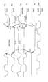
도 1a는 본 발명의 제 1 실시예에 따른 승압회로의 설명도,1A is an explanatory diagram of a boosting circuit according to a first embodiment of the present invention;
도 1b는 도 1a의 승압회로의 일부를 나타내는 도면,FIG. 1B is a view showing a part of the boosting circuit of FIG. 1A;
도 2는 본 발명의 제 1 실시예에 따른 승압회로의 동작을 나타내는 타이밍 차트,2 is a timing chart showing an operation of a boosting circuit according to a first embodiment of the present invention;
도 3은 본 발명의 제 1 실시예에 따른 승압회로의 동작을 나타내는 다른 타이밍 차트,3 is another timing chart showing the operation of the boosting circuit according to the first embodiment of the present invention;
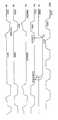
도 4는 본 발명의 제 2 실시예에 따른 승압회로의 설명도,4 is an explanatory diagram of a boosting circuit according to a second embodiment of the present invention;
도 5는 본 발명의 제 2 실시예에 따른 승압회로의 동작을 나타내는 타이밍 차트,5 is a timing chart showing an operation of a boosting circuit according to a second embodiment of the present invention;
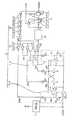
도 6은 본 발명의 제 3 실시예에 따른 승압회로의 설명도,6 is an explanatory diagram of a boosting circuit according to a third embodiment of the present invention;
도 7은 본 발명의 제 3 실시예에 따른 승압회로의 동작을 나타내는 타이밍 차트,7 is a timing chart showing an operation of a boosting circuit according to a third embodiment of the present invention;
도 8a는 센서 회로의 일례를 나타내는 도면,8A is a diagram illustrating an example of a sensor circuit;
도 8b는 센서 회로의 다른 예를 나타내는 도면,8B is a diagram illustrating another example of the sensor circuit;
도 9는 제어신호 생성회로의 진리표.9 is a truth table of a control signal generation circuit.
* 도면의 주요부분에 대한 부호의 설명* Explanation of symbols for main parts of the drawings
C1 : 제 1 승압용 커패시터 C2 : 제 2 승압용 커패시터C1: first boost capacitor C2: second boost capacitor
20 : 승압회로 21 : 논리회로20: boost circuit 21: logic circuit
23 : 제어신호 생성회로 Sc : 제어신호23: control signal generation circuit Sc: control signal
Ss : 센서신호 30 : 승압회로Ss: sensor signal 30: boost circuit
31 : 제어신호 생성회로(래치회로) 41 : 프리챠지 보상회로31: control signal generation circuit (latch circuit) 41: precharge compensation circuit
43 : 지연회로 C3 : 제 3 승압용 커패시터43: delay circuit C3: third boost capacitor
C4 : 제 4 승압용 커패시터 51 : 제 2 제어신호 생성회로C4: fourth boosting capacitor 51: second control signal generating circuit
53 : 제 2 논리회로53: second logic circuit
여기서는 승압회로 및 그 구동방법을 첨부된 도면을 참조하여 보다 상세히설명한다. 각 도면은 이 승압회로를 이해할 수 있는 정도로 개략적으로 나타낸 것에 지나지 않는다. 또한, 각 도면에 있어서 공통인 구성성분에 대해서는 같은 번호를 부착한다. 그 공통 구성성분에 대한 중복 설명은 생략한다.Here, the booster circuit and its driving method will be described in more detail with reference to the accompanying drawings. Each drawing is only a schematic representation of this voltage booster circuit. In addition, the same number is attached | subjected about the component which is common in each figure. Overlapping descriptions of the common constituents are omitted.
제 1 실시예(도 1a 및 도 1b 내지 도 3)First embodiment (Figs. 1A and 1B to 3)
도 1a 및 도 1b∼ 도 3은, 본 발명의 제 1 실시예에 따른 승압회로 및 그 구동방법을 나타낸다. 특히, 도 1a는 제 1 실시예의 승압회로(20)의 구성을 나타낸다. 도 2는 이 승압회로(20)의 승압동작을 설명하는 파형도이고, 도 3은 이 승압회로(20)가 승압동작을 정지시켰을 때의 승압회로의 승압동작을 설명하는 파형도이다.1A and 1B to 3 show a boost circuit and a driving method thereof according to a first embodiment of the present invention. In particular, Fig. 1A shows the configuration of the
승압회로(20)의 구성에 관해서 도 1a를 참조하여 설명한다.The configuration of the
이 승압회로(20)는, N 채널 MOS 트랜지스터(이후, NMOS라고 칭한다)로 각각 이루어진 제 1 및 제 2의 승압용 커패시터(C1, C2)와, 제 1∼제 4 스위칭 소자로서의 제 1∼제 4 NMOS 트랜지스터(T1∼ T4)와, 논리회로(21)와, 센서회로(13)와, 제어신호 생성회로(23)를 구비하고 있다.The
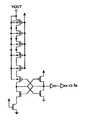
여기서, 트랜지스터(T1)의 드레인 및 승압용 커패시터(C1)의 제 1 전극(NMOS의 게이트 전극)은 노드(N3)에 각각 접속되어 있다. 트랜지스터(T2)의 드레인 및 승압용 커패시터(C2)의 제 1 전극(NMOS 트랜지스터의 게이트 전극)은 노드(N4)에 각각 접속되어 있다. 트랜지스터(T1, T2)의 소스에는 전원전위 레벨(VCC)(예를 들면, 5V)이 인가된다. 트랜지스터(T1)의 게이트는 노드(N4)에 접속되고, 트랜지스터(T2)의 게이트는 노드(N3)에 접속된다. 트랜지스터(T3, T4)는, 승압전압출력단자(VOUT)에 승압전위 레벨을 공급하기 위한 트랜지스터이다. 따라서, 트랜지스터(T3)는 승압전원 출력단자(VOUT)와 노드(N3) 사이에 접속되어 있고, 트랜지스터(T4)는 승압전원 출력단자(VOUT)와 노드(N4) 사이에 접속된다. 더구나, 트랜지스터(T3)의 게이트는 노드(N3)에 접속되어 있고, 트랜지스터(T4)의 게이트는 노드(N4)에 접속된다. 따라서, 트랜지스터(T3, T4)가 승압전압 출력단자(VOUT)에 노드(N3, N4)의 전위 레벨을 전송하더라도, 상기 승압전압 출력단자(VOUT)의 전위 레벨은 노드(N3, N4)에 전송되지 않는다.Here, the drain of the transistor T1 and the first electrode (the gate electrode of the NMOS) of the boosting capacitor C1 are connected to the node N3, respectively. The drain of the transistor T2 and the first electrode of the boost capacitor C2 (the gate electrode of the NMOS transistor) are connected to the node N4, respectively. The power supply potential level VCC (for example, 5V) is applied to the sources of the transistors T1 and T2. The gate of the transistor T1 is connected to the node N4, and the gate of the transistor T2 is connected to the node N3. The transistors T3 and T4 are transistors for supplying a boost potential level to the boost voltage output terminal VOUT. Therefore, the transistor T3 is connected between the boosted power supply output terminal VOUT and the node N3, and the transistor T4 is connected between the boosted power supply output terminal VOUT and the node N4. Moreover, the gate of the transistor T3 is connected to the node N3, and the gate of the transistor T4 is connected to the node N4. Therefore, even when the transistors T3 and T4 transfer the potential levels of the nodes N3 and N4 to the boosted voltage output terminal VOUT, the potential levels of the boosted voltage output terminal VOUT are transferred to the nodes N3 and N4. It doesn't work.
센서회로(13)는, 예를 들면 도 8a에 나타낸 것과 같은 회로로 구성된다. 이 센서회로(13)는, 승압전압 출력단자(VOUT)의 전위 레벨이 소정값보다 낮은 경우 로우 레벨(이후, 간단히 LOW라고 칭한다)을 출력하고, 소정값보다 큰 경우 하이 레벨(이후, 간단히 HIGH라고 칭한다)을 출력한다. 이 센서 회로(13)는 도 8a에 나타낸 것과 다른 회로, 예를 들면 도 8b에 나타낸 등가 회로의 기능을 만족하는 회로로 구성되어도 된다.The
논리회로(21)는, 제 1 게이트로서 제 1의 2입력 NOR 소자(21a), 제 2 게이트로서 제 2의 2입력 NOR 소자(21b) 및 제 3 게이트로서 인버터(21c)를 포함한다. 제 1의 2입력 NOR 소자(21a)의 출력은 승압용 커패시터(C1)의 제 2 전극에 접속되어 있는 노드(N1)에 접속되고, 제 2의 2입력 NOR 소자(21b)의 출력은 승압용 커패시터(C2)의 제 2 전극에 접속되어 있는 노드(N2)에 접속된다. 제 1 및 제 2의 2입력 NOR 소자(21a, 21b)의 한편의 출력은, 제 1 및 제 2의 2입력 NOR 소자(21a, 21b)의 다른 한편의 제 1입력에 각각 접속되어 있다. 따라서, 제 1 및 제 2의 2입력 NOR 소자(21a, 21)는, 플립플롭을 각각 구성한다.The
제 1의 2입력 NOR 소자(21a)의 제 2의 입력에는 제어신호 생성회로(23)로부터의 제어신호(Sc)가 입력되고, 제 2의 2입력 NOR 소자(21b)의 제 2의 입력에는 인버터(21c)를 통해 상기 제어신호(Sc)가 각각 입력된다. 제어신호(Sc)가 HIGH이면, 제 1의 2입력 NOR 소자(21a)의 출력은 LOW이다. 즉, 제어신호(Sc)가 HIGH이면, 논리회로(21)는 노드(N1)의 전위 레벨을 제 1전위 레벨(여기서는 로우 레벨)로 설정한다. 제 1의 2입력 NOR 소자(21a)의 출력이 LOW이면, 제 2의 2입력 NOR 소자(21b)의 제 1 입력은 LOW이다. 제어신호(Sc)가 HIGH이기 때문에, 제 2의 2입력 NOR 소자(21b)의 제 2 입력은 LOW이다. 따라서, 제 2의 2입력 NOR 소자(21b)의 출력은 HIGH이다. 즉, 제어신호(Sc)가 HIGH이면, 논리회로(21)는 노드(N2)의 전위 레벨을 제 2 전위레벨(하이 레벨)로 설정한다. 제어신호(Sc)가 LOW인 경우, 논리 회로(21)는 노드(N1, N2)의 각 전위 레벨을 상기한 상태와 반대의 상태로 변화시킬 수 있다.The control signal Sc from the control
제어신호 생성회로(23)는, 센서신호(Ss)를 입력하기 위한 인버터와, 해당 인버터의 출력을 입력하기 위한 제 1 입력 및 발진회로로부터의 발진신호(OSC)를 입력하기 위한 제 2 입력을 갖는 2입력 NAND 소자를 구비한다. 제어신호 생성회로(23)의 진리표는 도 9에 나타내었다. 동일 도면에 있어서, "0"은 각 신호의 전위가 LOW인 것을 나타내고, "1"은 각 신호의 전위가 HIGH인 것을 나타낸다. 도 9에 나타낸 바와 같이, 제어신호 생성회로(23)는 발진회로로부터 출력된 발진신호(OSC)를 출력하고, 센서신호(Ss)가 LOW인 경우, 제어신호(Sc)로서 HIGH/LOW를 교대로 논리회로(21)에 출력한다. 제어신호 생성회로(23)는 센서신호(Ss)가 HIGH인 경우, 발진 회로로부터 출력된 발진 신호(OSC)에 관계없이, 제어신호(Sc)로서 HIGH 신호를 논리회로(21)에 출력한다. 따라서, 도 1a에서의 승압회로(20)에 있어서, 승압 동작이 정지한 경우(센서신호(Ss)가 HIGH인 경우), 노드(N2)의 전위 레벨은 HIGH로 고정된다. 그 결과, 제 2 승압 커패시터(C2)에 접속된 노드(N4)의 전위 레벨이 승압된 상태를 유지한다.The control
이 제어신호 회로(23)의 구성은 도 1a의 예에 한정되지 않는다. 예를 들면, 도 1b에 나타낸 바와 같이, 제어신호 생성회로(23)는 발진회로부터 출력된 발진신호(OSC)와 센서신호(Ss)를 입력하는 2입력 NOR 소자로 구성되어도 된다. 그러한 경우에 있어서의 진리표는 도 9의 것과는 다르다. 승압동작이 정지한 경우(센서신호(Ss)가 HIGH인 경우), 노드(N1)의 전위레벨은 HIGH로 고정되기 때문에, 제 1 승압용커패시터(C1)에 처음에 접속된 전위레벨은 승압된 상태를 유지한다.The configuration of the
여기서는 도 1a에 나타낸 승압회로(20)의 동작을 설명한다.The operation of the
먼저, 도 2를 참조하여 승압동작을 설명한다.First, the boosting operation will be described with reference to FIG. 2.
승압전압 출력단자(VOUT)의 전위 레벨이 소정값보다 낮다고 가정하면, 센서회로(13)는 로우 레벨(접지 레벨)의 센서신호(Ss)를 출력한다. 이 때, 발진회로로부터의 발진신호(OSC)는 LOW에서 HIGH(VCC 레벨)로 변화된다고 가정한다. 따라서, (도 2의 발진신호(OSC)의 시간(t1)에서), 노드(N1)의 전위레벨이 LOW이고, 노드(N3)의 전위레벨이 승압된 전위 레벨(전원전위 레벨(VCC)보다 높은 전위 레벨인 VBOOST 레벨)로부터 강하하다.Assuming that the potential level of the boosted voltage output terminal VOUT is lower than a predetermined value, the
그 후, 노드(N1)의 전위 레벨이 LOW로 되면, 노드(N2)의 전위 레벨은 HIGH로 된다. (시간(t2)에서)노드(N4)의 전위레벨이 트랜지스터(T2)에 의해 VCC 레벨까지 이미 프리챠지되었기 때문에(트랜지스터(T2)의 게이트가 1개의 전 사이클에서 승압된 노드(N3)에 접속되기 때문에, 트랜지스터(T2)는 충분히 ON상태(이후, 간단히 ON이라고 칭한다)에 있다. 따라서, 노드(N4)의 전위레벨이 VCC레벨까지 정확히 프리챠지된다), 노드(N4)의 전위 레벨이 전원전위 레벨(VCC)보다 충분히 높은 전위레벨, 즉 실질적으로는 그것의 2배, 즉 2VCC의 전위 레벨까지 승압된다. 노드(N4)의 전위레벨이 승압되면, 트랜지스터(T4)는 전원전위 레벨(VCC)보다 충분히 높은 전위 레벨이 승압전압 출력단자(VOUT)에 공급되도록 ON한다. 노드(N4)의 전위 레벨이 승압되면, 트랜지스터(T1)는 ON한다. 따라서, 노드(N3)의 전위레벨이 전원전위 레벨(VCC)까지 정확히 프리챠지된다.Thereafter, when the potential level of the node N1 becomes LOW, the potential level of the node N2 becomes HIGH. Since the potential level of the node N4 (at time t2) has already been precharged to the VCC level by the transistor T2 (the gate of the transistor T2 is connected to the node N3 boosted in one full cycle). Thus, the transistor T2 is sufficiently in an ON state (hereinafter, simply referred to as ON), so that the potential level of the node N4 is correctly precharged to the VCC level), and the potential level of the node N4 becomes the power supply. It is stepped up to a potential level sufficiently higher than the potential level VCC, ie substantially twice its potential, that is, a potential level of 2 VCC. When the potential level of the node N4 is boosted, the transistor T4 is turned on so that a potential level sufficiently higher than the power supply potential level VCC is supplied to the boosted voltage output terminal VOUT. When the potential level of the node N4 is boosted, the transistor T1 is turned on. Therefore, the potential level of the node N3 is precisely precharged up to the power supply potential level VCC.
다음에, 발진신호(OSC)가 HIGH에서 LOW로 되면(시간(t3)),노드(N2)의 전위 레벨은 LOW이다. 노드(N2)의 전위 레벨이 LOW이면, 노드(N4)의 전위 레벨은 강하한다. 노드(N4)의 전위 레벨이 강하한 경우 트랜지스터(T4)는 OFF상태(이후, 간단히 OFF라고 칭한다)에 있기 때문에, 노드(N4)는 승압전압 출력단자(VOUT)로부터 전기적으로 절연된다. 게다가, 트랜지스터(T1)도 OFF이기 때문에, 노드(N3)는 전원전위 레벨(VCC)로부터 전기적으로 절연된다(트랜지스터(T1)에 의해 노드(N3)의 프리챠지 동작이 완료된다).Next, when the oscillation signal OSC goes from HIGH to LOW (time t3), the potential level of the node N2 is LOW. If the potential level of the node N2 is LOW, the potential level of the node N4 drops. When the potential level of the node N4 drops, the transistor T4 is in an OFF state (hereinafter simply referred to as OFF), so that the node N4 is electrically insulated from the boosted voltage output terminal VOUT. In addition, since the transistor T1 is also OFF, the node N3 is electrically insulated from the power supply potential level VCC (the precharge operation of the node N3 is completed by the transistor T1).
한편, 발진신호(OSC)가 HIGH에서 LOW로 되면(시간(t3)), 노드(N1)의 전위 레벨은 HIGH로 된다. (시간(t4)에서)노드(N1)의 전위레벨이 HIGH이면, 노드(N3)의 전위레벨이 승압된다. 노드(N3)의 전위레벨이 이미 트랜지스터(T1)에 의해 VCC레벨까지 프리챠지되었기 때문에(트랜지스터(T1)의 게이트가 1개의 전 사이클에서 승압된 노드(N4)에 접속되어 있기 때문에, 트랜지스터(T1)는 충분이 ON이다. 따라서, 노드(N3)의 전위 레벨이 VCC레벨까지 정확히 프리챠지된다), 노드(N3)의 전위 레벨은 전원전위 레벨(VCC)보다 충분히 높은 레벨, 즉, 실질적으로는 2VCC 레벨까지 승압된다. 노드(N3)의 전위 레벨이 승압되면, 트랜지스터(T3)는 ON하기 때문에, 전원전위 레벨(VCC)보다 충분히 높은 전위 레벨(VBOOST)은 승압전압 출력단자(VOUT)에 공급된다. 노드(N3)의 전위레벨이 승압되면, 트랜지스터(T2)는 충분히 ON한다. 따라서, 노드(N4)의 전위 레벨이 VCC 레벨까지 정확히 프리챠지(precharge)된다.On the other hand, when the oscillation signal OSC goes from HIGH to LOW (time t3), the potential level of the node N1 becomes HIGH. If the potential level of the node N1 is HIGH (at time t4), the potential level of the node N3 is boosted. Since the potential level of the node N3 has already been precharged to the VCC level by the transistor T1 (the gate of the transistor T1 is connected to the node N4 boosted in one full cycle, the transistor T1). ) Is sufficiently ON, therefore, the potential level of the node N3 is exactly precharged to the VCC level), and the potential level of the node N3 is sufficiently higher than the power supply potential level VCC, that is, substantially Step up to 2VCC level. When the potential level of the node N3 is boosted, the transistor T3 is turned on, so that the potential level VBOOST sufficiently higher than the power supply potential level VCC is supplied to the boosted voltage output terminal VOUT. When the potential level of the node N3 is boosted, the transistor T2 is sufficiently turned on. Therefore, the potential level of the node N4 is precisely precharged up to the VCC level.
다음에, 센서신호(Ss)에 응답하여 승압동작을 정지 또는 재개하는 동작을 도 3을 참조하여 설명한다.Next, an operation of stopping or resuming the boosting operation in response to the sensor signal Ss will be described with reference to FIG. 3.
승압전압 출력단자(VOUT)의 전위레벨이 소정값을 초과하면, 센서회로(13)는 승압전압 출력단자(VOUT)의 전위레벨이 충분히 하이라는 것을 제어신호 생성회로(23)에게 알리기 위해 하이 레벨의 센서신호(Ss)를 출력한다.When the potential level of the boosted voltage output terminal VOUT exceeds a predetermined value, the
센서신호(Ss)가 제 1 신호인 L에서 제 2 신호인 H로 변경되면(시간(t11)), 제어신호 생성회로(23)는 HIGH로 고정된 제어신호(Sc)를 논리회로(21)에 출력한다. (도 9의 진리표 참조)제어신호(Sc)가 HIGH이면, 노드(N1)의 전위레벨이 LOW로 고정된 후(시간(t12)), 노드(N2)의 전위 레벨은 노드(N1)보다 조금 늦게 HIGH로 고정된다(시간(t 13)). 노드(N1)의 전위 레벨이 LOW이면, 노드(N3)의 전위 레벨은 강하한다. 노드(N2)의 전위 레벨이 HIGH이고, 노드(N4)의 전위 레벨이 이전 사이클에서 프리챠지되기 때문에, 노드(N4)의 전위 레벨은 VBOOST 레벨까지 승압된다. 노드(N4)의 전위레벨이 전원전위 레벨(VCC)보다 충분히 높기 때문에, 트랜지스터(T1)는 충분히 ON한다. 따라서, 노드(N3)의 전위 레벨이 VCC 레벨까지 프리챠지되어 유지된다.When the sensor signal Ss is changed from L, which is the first signal, to H, which is the second signal (time t11), the control
본 발명의 특징은 센서신호(Ss)가 HIGH인 경우, 즉 승압동작이 정지한 경우, 노드(N2)(노드(N1))의 전위레벨이 HIGH를 유지하기 때문에, 노드(N4)(노드(N3))의 전위레벨은 승압레벨(VBOOST)을 유지한다는 점에 있다. 노드(N4)(노드(N3))의 전위레벨이 VBOOST레벨을 유지하면, 게이트에 VBOOST레벨이 공급되는 트랜지스터(T1)(트랜지스터(T2))는 충분히 ON하고, 프리챠지될 노드(N3)(노드(N4))의 전위레벨은 VCC레벨을 유지한다. 그 결과, 승압동작이 재개된 경우 프리챠지되었던 노드(N3)(노드(N4))의 전위레벨이 충분한 승압레벨(VBOOST레벨)까지 승압된다. 프리챠지된 레벨이 VCC레벨보다 낮으면, 승압레벨은 변함없이 저하한다.A feature of the present invention is that when the sensor signal Ss is HIGH, that is, when the boosting operation is stopped, the potential level of the node N2 (node N1) is kept high, so that the node N4 (node ( The potential level of N3)) is maintained at the boost level VBOOST. When the potential level of the node N4 (node N3) maintains the VBOOST level, the transistor T1 (transistor T2) to which the VBOOST level is supplied to the gate is sufficiently turned ON, and the node N3 (to be precharged) ( The potential level of the node N4 maintains the VCC level. As a result, when the boosting operation is resumed, the potential level of the node N3 (node N4) that has been precharged is boosted to a sufficient boosting level (VBOOST level). If the precharged level is lower than the VCC level, the boosting level remains unchanged.
그래서, 승압전압 출력단자(VOUT)의 전위레벨이 소정값보다 낮으면, 센서회로(13)는, 승압전압 출력단자(VOUT)의 전위레벨이 저하한다는 것을 제어신호 생성회로(23)에게 알리기 위해 낮은 레벨의 센서신호(Ss)를 출력한다. (시간(t14)에서)센서신호(Ss)의 전위레벨이 LOW로 되면, 발진신호(OSC)는 제어신호로서 도 9에 나타낸 바와 같이 논리회로(21)에 출력된다. 따라서, 노드(N1, N2)의 전위레벨은 발진신호(OSC)의 전위레벨에 응답하여 교대로 LOW 및 HIGH로 변경된다.Thus, when the potential level of the boosted voltage output terminal VOUT is lower than the predetermined value, the
상기 언급된 바와 같이, 본 발명에 의하면, 승압노드(N3 및 N4)의 전위레벨중의 하나는, 승압동작이 센서신호에 응답하여 정지된 경우에 승압된 상태로 항상 있기 때문에, 승압노드의 전위레벨의 다른 하나는 충분히 프리챠지될 수 있다. 그 결과, 항상 안정된 승압레벨을 공급할 수 있는 승압회로를 제공할 수 있다.As mentioned above, according to the present invention, one of the potential levels of the boost nodes N3 and N4 is always in the boosted state when the boost operation is stopped in response to the sensor signal, so that the potential of the boost node is increased. The other of the levels can be sufficiently precharged. As a result, it is possible to provide a boosting circuit that can always supply a stable boosting level.
제 2 실시예(도 4 및 도 5)Second Embodiment (FIGS. 4 and 5)
본 발명의 제 2 실시예에 따른 승압회로 및 그 구동방법을 도 4 및 도 5를 참조하여 설명한다.A booster circuit and a driving method thereof according to a second embodiment of the present invention will be described with reference to FIGS. 4 and 5.
도 4는 본 발명의 제 2 실시예에 따른 승압회로(30)의 구성을 나타내고, 도 5는 승압회로(30)가 그것의 승압동작을 정지시킨 경우의 동작을 주로 설명하는 파형도이다.4 shows the configuration of the boosting
승압회로(20)와 승압회로(30)의 차이점은, 제어신호 생성회로(31)의 유무에 있다. 이 제어신호 생성회로(31)는, 센서신호(Ss)가 제 1 신호(로우레벨)인 경우에 논리회로(21)에 발진신호(OSC)를 출력하거나, 발진신호(OSC)의 상태를 래치(latch)하고, 센서신호(Ss)가 제 2 신호(하이레벨)인 경우에 논리회로(21)에 래치된 발진신호(OSC)를 출력하는 래치회로를 포함한다.The difference between the
구체적으로, 제어신호 생성회로(31)는, 인버터(31a), 트랜스퍼 게이트(31b), 클록(clock)된 인버터(31c) 및 인버터(31d)를 구비한다. 인버터(31a)의 출력은 논리회로(21)의 제 1의 2입력 NOR 소자(21a)의 한편의 입력 및 인버터(21c)의 입력에 접속되는 노드(N5)에 접속된다. 제 1 인버터(31a)의 입력은 트랜스퍼 게이트(31b)의 출력에 접속되는 노드(N6)에 접속된다. 트랜스퍼 게이트(31b)의 입력에는 발진신호(OSC)가 입력되어 있다. 또한, 트랜스퍼 게이트(31b)의 PMOS 트랜지스터의 게이트에는 센서신호(Ss)가 입력되지만, NMOS 트랜지스터의 게이트에는 인버터(31d)의 출력이 접속된다. 이 인버터(31d)의 입력에는 또한 센서신호(Ss)가 입력된다. 클록된 인버터(31c)의 출력은 노드(N6)에 접속되고, 그 입력은 노드(N5)에 접속된다. 이 클록된 인버터(31c)의 PMOS 트랜지스터의 게이트는 인버터(31d)의 출력에 접속되고, NMOS 트랜지스터의 게이트에는 센서신호(Ss)가 입력된다.Specifically, the control
다음에, 이 승압회로(30)의 동작을 설명한다. 승압회로(30)의 승압동작은 상술의 승압회로(20)의 경우의 동작과 동일하기 때문에 그 설명은 생략하지만, 승압동작의 정지 및 재개 동작은 도 5를 참조하여 설명한다. 센서신호(Ss)가 LOW에서 HIGH로(시간(t1)에서) 되면, 트랜스퍼 게이트(31b)는 OFF하고, 클록된 인버터(31c)는 ON한다. 따라서, 제어신호 생성회로(31)는 발진신호(OSC)의 현재의 전위레벨을 래치한다. 그 결과, 발진신호(OSC)의 전위레벨이 그 후에 변화하더라도, 승압회로(30)의 각 노드의 전위레벨은 현재의 상태를 유지한다. 예를 들면, 센서신호(Ss)가 하이레벨로 래치되면, 노드(N1)의 전위레벨은 HIGH로 고정되고, 노드(N2)의 전위레벨은 LOW로 고정된다.Next, the operation of the
본 발명에 의하면, 승압동작이 정지한 경우, 승압동작이 정지하기 전의 상태를 즉시 유지할 수 있다. 따라서, 본 발명에 따르면, 상기 승압회로는 어떤 트러블 때문에 리셋트되거나, 승압 또는 프리챠지 동작 중에 정지되는 일은 없다.According to the present invention, when the boosting operation is stopped, the state before the boosting operation is stopped can be immediately maintained. Therefore, according to the present invention, the boosting circuit is not reset due to any trouble or stopped during the boosting or precharging operation.
그래서, 센서신호(Ss)의 전위레벨이 HIGH에서 LOW로 되면, 트렌스퍼 게이트(transfer gate)(31b)는 ON하고, 클록된 인버터(31c)는 OFF하여, 래칭 동작을 해제한다. 제어신호 생성회로(31)는, 승압회로(30)가 승압동작을 다시 수행하도록 논리회로(21)에 발진신호(OSC)의 것에 대응하는 전위레벨을 출력한다.Therefore, when the potential level of the sensor signal Ss goes from HIGH to LOW, the
본 발명에 따르면, 상기 발진신호(OSC)는, 승압 동작이 센서신호(Ss)를 이용하여 정지된 경우 래치되기 때문에, 승압회로가 리셋된 경우 발생하는, 승압노드(노드(N3, N4))의 프리챠지된 레벨이 저하하는 것을 방지할 수 잇다.According to the present invention, the oscillation signal OSC is latched when the boosting operation is stopped using the sensor signal Ss, so that the boosting node (nodes N3 and N4) which occurs when the boosting circuit is reset. It is possible to prevent the precharged level from decreasing.
제 3 실시예(도 6 및 도 7)Third Embodiment (FIGS. 6 and 7)
승압동작이 장시간 동안 정지한 경우에, 승압노드(노드(N3, N4))의 전위레벨이 저하한다는 것은 부정할 수 없다. 특히, 프리챠지 동작이 선택된 승압노드(노드 (N3 및 N4))의 전위레벨이 저하하면, 그것의 전위레벨은 승압동작이 재개되어 전원전위 레벨보다 충분히 높은 전위 레벨이 승압전압 출력단자(VOUT)에 입력되기 어려운 경우에, 부정확하게 저하한다. 또한, 초당 프리챠지 동작이 정상적으로 수행되지 않는 가능성을 부정할 수 없다.When the boosting operation is stopped for a long time, it cannot be denied that the potential level of the boosting nodes (nodes N3 and N4) decreases. In particular, when the potential level of the boosting node (nodes N3 and N4) in which the precharge operation is selected decreases, the potential level thereof resumes, and the potential level higher than the power supply potential level is raised to the boost voltage output terminal VOUT. If it is difficult to input the data, it is incorrectly lowered. In addition, it is impossible to deny the possibility that the precharge operation per second is not normally performed.
제 3 실시예는 이 문제점을 해결한 승압회로를 제공한다. 도 6은 제 3 실시예의 승압회로(40)를 나타낸다. 승압회로(40)는 도 4의 승압회로(30) 뿐만 아니라 프리챠지 보상회로(41)와 지연회로(43)를 포함한다. 이하, 프리챠지 보상회로(41) 및 지연회로(43)에 관해서 주로 설명한다.The third embodiment provides a boosting circuit that solves this problem. 6 shows the
이 경우의 프리챠지 보상회로(41)는, 제 5∼제 8 스위칭 소자로서의 NMOS 트랜지스터(T5∼ T8), 제 3 및 제 4 승압용 커패시터로서의 MOS 커패시터(C3 및 C4), 제 2 제어신호 생성회로(51) 및 제 2 논리회로(53)를 구비한다.In this case, the
트랜지스터(T5)는, 노드(N3)에 접속된 드레인, 프리챠지 전원(VCC)에 접속된 소스 및 승압용 커패시터(C3)의 제 1 전극에 접속된 게이트를 포함한다. 트랜지스터(T7)는, 노드(N4)에 접속된 드레인, 프리챠지용 전원(VCC)에 접속된 소스, 승압용 커패시터(C4)의 제 1 전극에 접속된 게이트를 포함한다. 트랜지스터(T6)는, 노드(N7)의 전위레벨이 (VCC-VT)의 전위레벨보다 저하하는 것을 방지하기 위한 트랜지스터이고, 그것은 다이오드로서 전원(VCC) 및 노드(N7) 사이에 접속되어 있다. 트랜지스터(T8)는, 노드(N8)의 전위레벨이 (VCC-VT)의 전위레벨보다 저하하는 것을 방지하기 위한 트랜지스터이고, 그것은 다이오드로서 전원(VCC)과 노드(N8) 사이에 접속되어 있다.The transistor T5 includes a drain connected to the node N3, a source connected to the precharge power supply VCC, and a gate connected to the first electrode of the boost capacitor C3. The transistor T7 includes a drain connected to the node N4, a source connected to the precharge power supply VCC, and a gate connected to the first electrode of the boost capacitor C4. The transistor T6 is a transistor for preventing the potential level of the node N7 from falling below the potential level of the VCC-VT, which is connected between the power supply VCC and the node N7 as a diode. The transistor T8 is a transistor for preventing the potential level of the node N8 from falling below the potential level of the VCC-VT, which is connected between the power supply VCC and the node N8 as a diode.
제 2 제어신호 생성회로(51)는 제 2 신호(하이레벨)에서 제 1 신호(로우레벨)로의 센서신호(Ss)의 변화에 응답하여 소정의 시간폭을 갖는 제 2 제어신호(Sc2)를 생성한다. 즉, 제 2 제어신호 생성회로(51)는 제 2 신호(하이레벨)에서 제 1 신호(로우레벨)로의 센서신호(Ss)의 변화에 응답하여 원쇼트 펄스(one shot pulse)를 생성한다. 구체적으로, 제 2 제어신호 생성회로(51)는 NAND 소자(51a)와, 제 1∼제 4 인버터(51b∼51e)를 구비한다. 제 1∼제 4 인버터(51b∼51e)는 서로 직렬 접속되어 있다. 제 1 인버터(51a)의 출력 및 제 4 인버터(51e)의 출력을 NAND 소자(51a)에 입력하여, 제 2 제어신호(Sc2)를 출력한다.The second control
제 2 논리회로(53)는 승압용 커패시터(C3)의 제 2 전극에 접속되는 노드(N9)에 접속된 출력, 인버터(21c)의 출력을 입력하기 위한 제 1 입력 및 제 2 제어신호(Sc2)를 입력하기 위한 제 2 입력을 갖는 2입력 NOR 소자(53a)와, 승압용 커패시터(C4)의 제 2 전극에 접속되는 노드(N10)에 접속된 출력, 인버터(21c)의 출력을 입력하기 위한 제 1 입력 및 제 2 제어신호(Sc2)를 입력하기 위한 제 2 입력을 갖는 2입력 NOR 소자(53b)로 구성된다.The
지연회로(43)는, 제어신호 생성회로(31)와 논리회로(21) 사이에 접속되어 있고, 소정시간만큼 제어신호 생성회로에서 출력되는 제어신호(Sc)를 지연시키기 위한 것이다. 지연시간은 프리챠지 보상회로(41)에 의한 프리챠지에 필요한 시간을 고려하여 설정한다. 이 지연회로(43)의 구체적인 구성은 나타내지 않았지만, 지연회로(43)는 지연동작을 실현시키면 어떠한 구성을 가져도 된다.The
다음에, 도 6 및 도 7을 참조하여 승압회로(40)의 동작을 설명한다. 승압동작은 전술의 승압회로(20 및 30)와 마찬가지이기 때문에, 여기서는 생략하지만, 승압동작을 정지하는 동작 및 재개하는 동작에 관해서는 설명한다.Next, the operation of the
센서신호(Ss)가 LOW에서 HIGH로 되면(시간(t1)), 트랜스퍼 게이트(31b)는 OFF하고, 클록된 게이트(31c)는 ON하기 때문에, 발진신호(OSC)의 전위레벨은 래치된다. 따라서, 이후에 발진신호(OSC)가 변화하더라도, 승압회로의 각 노드의 전위레벨은 현재의 상태를 유지한다. 노드(N3)의 전위레벨이 시간(t1)에서 승압된다고 (VBOOST 레벨로 승압되면) 가정하면, 트랜지스터(T2)가 ON하여, 노드(N4)의 전위레벨이 트랜지스터(T2)를 통해서 VCC 레벨까지 프리챠지된다. 그러나, 이 상태가 장시간 동안 계속되면, 노드(N3)의 전위레벨은 저하하고(시간(t2)), 최종적으로 그것은 VCC레벨보다 낮은 레벨까지 저하하기 때문에 노드(N4)의 전위레벨도 (VCC-Vt)의 레벨까지 저하한다(시간t2). 센서신호(Ss)가 HIGH에서 LOW로 되고(시간t3), 승압동작이 재개되면, 노드(N4)의 전위레벨이 VCC레벨까지 충분히 프리챠지되지 않기 때문에, 충분한 승압레벨을 얻을 수 없다.When the sensor signal Ss goes from LOW to HIGH (time t1), the
본 발명에서는, 제 3 실시예에 의하면, 프리챠지 보상회로(41) 및 지연회로(43)가 제공된다. 제 3실시예의 동작을 이하 설명한다.In the present invention, according to the third embodiment, the
승압동작의 정지기간 동안 노드(N3) 및 노드(N4) 각각의 전위레벨이(VCC-Vt)의 레벨까지 강하한다고 가정한다. 이 상태에서, 센서신호(Ss)가 HIGH에서 LOW로 되면, 제 2 제어신호 생성회로(51)는 원쇼트 펄스를 출력한다. 2입력 NOR 소자(53b)는 원쇼트 펄스 및 노드(N5)의 전위레벨에 응답하여 프리챠지가 필요한 노드(Nl0)에 원쇼트 펄스를 출력한다. 그 결과, 노드(N8)의 전위레벨이 승압용 커패시터(C4)에 의해 승압된다. 트랜지스터(T7)는 승압된 노드(N8)의 전위레벨의 입력시 충분히 ON하여, 노드(N4)의 전위레벨을 VCC 레벨까지 프리챠지한다. 그 후, 지연회로(43)에 의해 지연된 제어신호(Sc)가 논리회로(21)에 입력되어 제 1 및 제 2 실시예와 같은 방법으로 노드(N4)의 승압동작을 수행한다. 노드(N4)의 전위레벨이 이 승압동작으로 VCC레벨까지 충분히 프리챠지되기 때문에, VCC레벨보다 충분히 높은 승압레벨을 노드(N4)의 전위레벨로서 얻을 수 있다. 이 후, 승압동작이 제어신호(Sc)(발진신호(OSC)에 의해 반복된다.It is assumed that the potential level of each of the nodes N3 and N4 drops to the level of VCC-Vt during the stop period of the boost operation. In this state, when the sensor signal Ss goes from HIGH to LOW, the second control
상술한 바과 같이, 제 3 실시예에 의하면, 승압동작이 장시간 동안 정지되더라도 적합한 상태에서는 승압동작이 재개될 수 있어, 승압동작이 재개되면 소정의 프리챠지 동작이 수행될 수 있기 때문에 프리챠지 레벨은 저하한다.As described above, according to the third embodiment, even if the boosting operation is stopped for a long time, the boosting operation can be resumed in a suitable state, and the precharge level can be performed because the predetermined precharge operation can be performed when the boosting operation is resumed. Lowers.
상기의 설명으로부터 분명한 바와 같이 승압동작을 정지한 경우에도, 제 1및 제 2 승압용 커패시터 중의 한편의 승압용 커패시터를 승압된 상태로 할 수 있기 때문에, 다른 한편의 승압용 커패시터를 프리챠지하기 위한 스위칭 소자는 해당 승압된 한편의 승압용 커패시터에서의 레벨에 따라서 온상태로 된다.As apparent from the above description, even when the boosting operation is stopped, the boosting capacitor of one of the first and second boosting capacitors can be in a boosted state. The switching element is turned on in accordance with the level at the boosted capacitor.
따라서, 승압동작의 정지시에 있어서도, 제 1 및 제 2 승압용 커패시터 중 어느 한편은 프리챠지된다.Therefore, even when the boosting operation is stopped, either one of the first and second boosting capacitors is precharged.
그 때문에, 종래와 비교하여 승압효율을 개선할 수 있다.Therefore, the boosting efficiency can be improved as compared with the conventional one.
또한, 승압동작을 정지할 때, 제 1 및 제 2 승압용 커패시터에 실제로 이루어진 동작상태가 유지된 상태로 승압동작이 정지된다.Further, when the boosting operation is stopped, the boosting operation is stopped while the operating state actually made on the first and second boosting capacitors is maintained.
따라서, 프리챠지 동작이 선택된 측의 승압용 커패시터는 소정레벨까지 프리챠지되기 때문에, 승압동작의 정지 타이밍에 관계없이, 승압동작이 재개된 경우에 해당 승압동작이 이루어진다.Therefore, since the boosting capacitor on the side where the precharge operation is selected is precharged to a predetermined level, the boosting operation is performed when the boosting operation is resumed regardless of the timing of stopping the boosting operation.
그 때문에, 효율이 좋은 승압이 수행될 수 있고, 더구나 오동작도 생기지 않는다.Therefore, efficient boosting can be performed, and no malfunction occurs.
또한, 승압동작 재개에 있어서 소정의 프리챠지를 우선 실시하는 구성의 경우, 승압동작의 정지시간이 긴 경우의 프리챠지레벨의 저하를 시정할 수 있기 때문에, 장시간 승압동작을 정지한 후에 승압동작을 재개한 경우도 효율이 좋은 승압을 수행할 수 있다.In addition, in the case of a configuration in which the predetermined precharge is first performed when the boosting operation is resumed, the decrease in the precharge level when the stop time of the boosting operation is long can be corrected. Therefore, the boosting operation is stopped after the boosting operation is stopped for a long time. Even if it resumes, efficient boosting can be performed.
Claims (13)
Translated fromKoreanApplications Claiming Priority (2)
| Application Number | Priority Date | Filing Date | Title |
|---|---|---|---|
| JP133122 | 1996-05-28 | ||
| JP8133122AJPH09320267A (en) | 1996-05-28 | 1996-05-28 | Boosting circuit driving method and boosting circuit |
Publications (2)
| Publication Number | Publication Date |
|---|---|
| KR970076800A KR970076800A (en) | 1997-12-12 |
| KR100347355B1true KR100347355B1 (en) | 2002-10-25 |
Family
ID=15097312
Family Applications (1)
| Application Number | Title | Priority Date | Filing Date |
|---|---|---|---|
| KR1019970015133AExpired - Fee RelatedKR100347355B1 (en) | 1996-05-28 | 1997-04-23 | Booster circuit and method of driving the same |
Country Status (6)
| Country | Link |
|---|---|
| US (1) | US5781426A (en) |
| EP (1) | EP0810720A3 (en) |
| JP (1) | JPH09320267A (en) |
| KR (1) | KR100347355B1 (en) |
| CN (1) | CN1173023A (en) |
| TW (1) | TW378324B (en) |
Families Citing this family (10)
| Publication number | Priority date | Publication date | Assignee | Title |
|---|---|---|---|---|
| JPH11308855A (en)* | 1998-04-20 | 1999-11-05 | Nec Corp | Boosting circuit |
| JP3698550B2 (en)* | 1998-07-02 | 2005-09-21 | 富士通株式会社 | Boost circuit and semiconductor device using the same |
| JP4394835B2 (en)* | 1998-11-18 | 2010-01-06 | マクロニクス インターナショナル カンパニー リミテッド | High-speed on-chip voltage generator for low power integrated circuits |
| JP3726041B2 (en)* | 2001-07-24 | 2005-12-14 | エルピーダメモリ株式会社 | Booster circuit and driving method thereof |
| US7184284B2 (en)* | 2004-03-30 | 2007-02-27 | Micron Technology, Inc. | Closed-loop high voltage booster |
| CN103326578B (en)* | 2012-03-19 | 2016-03-02 | 旺宏电子股份有限公司 | booster system |
| CN102624232B (en)* | 2012-04-20 | 2014-06-25 | 矽力杰半导体技术(杭州)有限公司 | Precharging circuit and method for DC-DC boost converter |
| US9214859B2 (en) | 2012-04-30 | 2015-12-15 | Macronix International Co., Ltd. | Charge pump system |
| US9536575B2 (en) | 2015-01-14 | 2017-01-03 | Macronix International Co., Ltd. | Power source for memory circuitry |
| US9881654B2 (en) | 2015-01-14 | 2018-01-30 | Macronix International Co., Ltd. | Power source for memory circuitry |
Citations (6)
| Publication number | Priority date | Publication date | Assignee | Title |
|---|---|---|---|---|
| JPH04102292A (en)* | 1990-08-20 | 1992-04-03 | Fujitsu Ltd | boost circuit |
| JPH06187788A (en)* | 1992-12-17 | 1994-07-08 | Mitsubishi Electric Corp | Boosting circuit |
| KR940017062A (en)* | 1992-12-05 | 1994-07-25 | 김광호 | Word Line Boosting Circuit and Control Circuit of Semiconductor Integrated Circuits |
| JPH076582A (en)* | 1992-11-12 | 1995-01-10 | Matsushita Electric Ind Co Ltd | Level detection circuit and step-up power supply generation circuit using the same |
| JPH0745074A (en)* | 1993-07-29 | 1995-02-14 | Mitsubishi Electric Corp | Semiconductor memory device |
| JPH07122066A (en)* | 1993-10-28 | 1995-05-12 | Sony Corp | Boosting circuit |
Family Cites Families (7)
| Publication number | Priority date | Publication date | Assignee | Title |
|---|---|---|---|---|
| US4110639A (en)* | 1976-12-09 | 1978-08-29 | Texas Instruments Incorporated | Address buffer circuit for high speed semiconductor memory |
| US5055840A (en)* | 1990-01-16 | 1991-10-08 | Carroll Touch Incorporated | Infrared touch input device and light emitted activation circuit |
| KR920006991A (en)* | 1990-09-25 | 1992-04-28 | 김광호 | High Voltage Generation Circuit of Semiconductor Memory Device |
| JP3020345B2 (en)* | 1992-05-19 | 2000-03-15 | 株式会社 沖マイクロデザイン | Semiconductor memory circuit |
| JP2755047B2 (en)* | 1992-06-24 | 1998-05-20 | 日本電気株式会社 | Boost potential generation circuit |
| KR100285974B1 (en)* | 1992-11-18 | 2001-04-16 | 사와무라 시코 | Step-up Power Generation Circuit |
| US5661419A (en)* | 1996-05-23 | 1997-08-26 | Sun Microsystems, Inc. | Dynamic phase-frequency detector circuit |
- 1996
- 1996-05-28JPJP8133122Apatent/JPH09320267A/ennot_activeWithdrawn
- 1997
- 1997-02-22TWTW086102162Apatent/TW378324B/ennot_activeIP Right Cessation
- 1997-03-18EPEP97301785Apatent/EP0810720A3/ennot_activeWithdrawn
- 1997-03-31USUS08/829,175patent/US5781426A/ennot_activeExpired - Lifetime
- 1997-04-23KRKR1019970015133Apatent/KR100347355B1/ennot_activeExpired - Fee Related
- 1997-05-28CNCN97105546Apatent/CN1173023A/enactivePending
Patent Citations (6)
| Publication number | Priority date | Publication date | Assignee | Title |
|---|---|---|---|---|
| JPH04102292A (en)* | 1990-08-20 | 1992-04-03 | Fujitsu Ltd | boost circuit |
| JPH076582A (en)* | 1992-11-12 | 1995-01-10 | Matsushita Electric Ind Co Ltd | Level detection circuit and step-up power supply generation circuit using the same |
| KR940017062A (en)* | 1992-12-05 | 1994-07-25 | 김광호 | Word Line Boosting Circuit and Control Circuit of Semiconductor Integrated Circuits |
| JPH06187788A (en)* | 1992-12-17 | 1994-07-08 | Mitsubishi Electric Corp | Boosting circuit |
| JPH0745074A (en)* | 1993-07-29 | 1995-02-14 | Mitsubishi Electric Corp | Semiconductor memory device |
| JPH07122066A (en)* | 1993-10-28 | 1995-05-12 | Sony Corp | Boosting circuit |
Also Published As
| Publication number | Publication date |
|---|---|
| EP0810720A2 (en) | 1997-12-03 |
| US5781426A (en) | 1998-07-14 |
| KR970076800A (en) | 1997-12-12 |
| TW378324B (en) | 2000-01-01 |
| JPH09320267A (en) | 1997-12-12 |
| CN1173023A (en) | 1998-02-11 |
| EP0810720A3 (en) | 1999-10-20 |
Similar Documents
| Publication | Publication Date | Title |
|---|---|---|
| US5521547A (en) | Boost voltage generating circuit | |
| US5786711A (en) | Data output buffer for use in a semiconductor memory device | |
| US6333670B1 (en) | Semiconductor device capable of stably generating internal voltage with low supply voltage | |
| US6208197B1 (en) | Internal charge pump voltage limit control | |
| KR19990030115A (en) | Semiconductor Integrated Circuits with Three-State Logic Gate Circuits | |
| JP3043201B2 (en) | Boost circuit | |
| KR100336254B1 (en) | Booster circuit | |
| KR100347355B1 (en) | Booster circuit and method of driving the same | |
| KR100279296B1 (en) | Step-up voltage generator circuit | |
| US5952851A (en) | Boosted voltage driver | |
| KR19990050472A (en) | Step-up Voltage Generation Circuit | |
| US4716303A (en) | MOS IC pull-up circuit | |
| US5638013A (en) | Charge redistribution circuit and method | |
| US6226206B1 (en) | Semiconductor memory device including boost circuit | |
| KR100462863B1 (en) | High voltage generating circuit and method | |
| JPH1145574A (en) | Semiconductor storage device | |
| US6700436B2 (en) | Method and circuit for generating a high voltage | |
| US5587956A (en) | Semiconductor memory device having function of generating boosted potential | |
| US6850110B2 (en) | Voltage generating circuit and method | |
| KR100316982B1 (en) | Semiconductor memory device having push-pull type output circuit formed by two n-channel mos transistors | |
| KR100418719B1 (en) | Pumping circuit for flash memory device | |
| KR100218333B1 (en) | Boot-strap circuit | |
| KR100238867B1 (en) | Boosting circuits of semiconductor meory device | |
| JPH07287980A (en) | Power supply voltage generation circuit for semiconductor memory device | |
| KR100407989B1 (en) | Circuit for Generating High Voltage |
Legal Events
| Date | Code | Title | Description |
|---|---|---|---|
| PA0109 | Patent application | St.27 status event code:A-0-1-A10-A12-nap-PA0109 | |
| R17-X000 | Change to representative recorded | St.27 status event code:A-3-3-R10-R17-oth-X000 | |
| R17-X000 | Change to representative recorded | St.27 status event code:A-3-3-R10-R17-oth-X000 | |
| R17-X000 | Change to representative recorded | St.27 status event code:A-3-3-R10-R17-oth-X000 | |
| PG1501 | Laying open of application | St.27 status event code:A-1-1-Q10-Q12-nap-PG1501 | |
| A201 | Request for examination | ||
| P11-X000 | Amendment of application requested | St.27 status event code:A-2-2-P10-P11-nap-X000 | |
| P13-X000 | Application amended | St.27 status event code:A-2-2-P10-P13-nap-X000 | |
| PA0201 | Request for examination | St.27 status event code:A-1-2-D10-D11-exm-PA0201 | |
| D13-X000 | Search requested | St.27 status event code:A-1-2-D10-D13-srh-X000 | |
| D14-X000 | Search report completed | St.27 status event code:A-1-2-D10-D14-srh-X000 | |
| E701 | Decision to grant or registration of patent right | ||
| PE0701 | Decision of registration | St.27 status event code:A-1-2-D10-D22-exm-PE0701 | |
| GRNT | Written decision to grant | ||
| PR0701 | Registration of establishment | St.27 status event code:A-2-4-F10-F11-exm-PR0701 | |
| PR1002 | Payment of registration fee | St.27 status event code:A-2-2-U10-U11-oth-PR1002 Fee payment year number:1 | |
| PG1601 | Publication of registration | St.27 status event code:A-4-4-Q10-Q13-nap-PG1601 | |
| PR1001 | Payment of annual fee | St.27 status event code:A-4-4-U10-U11-oth-PR1001 Fee payment year number:4 | |
| PR1001 | Payment of annual fee | St.27 status event code:A-4-4-U10-U11-oth-PR1001 Fee payment year number:5 | |
| PR1001 | Payment of annual fee | St.27 status event code:A-4-4-U10-U11-oth-PR1001 Fee payment year number:6 | |
| PR1001 | Payment of annual fee | St.27 status event code:A-4-4-U10-U11-oth-PR1001 Fee payment year number:7 | |
| R18-X000 | Changes to party contact information recorded | St.27 status event code:A-5-5-R10-R18-oth-X000 | |
| PN2301 | Change of applicant | St.27 status event code:A-5-5-R10-R11-asn-PN2301 | |
| PN2301 | Change of applicant | St.27 status event code:A-5-5-R10-R14-asn-PN2301 | |
| PR1001 | Payment of annual fee | St.27 status event code:A-4-4-U10-U11-oth-PR1001 Fee payment year number:8 | |
| PR1001 | Payment of annual fee | St.27 status event code:A-4-4-U10-U11-oth-PR1001 Fee payment year number:9 | |
| R18-X000 | Changes to party contact information recorded | St.27 status event code:A-5-5-R10-R18-oth-X000 | |
| PR1001 | Payment of annual fee | St.27 status event code:A-4-4-U10-U11-oth-PR1001 Fee payment year number:10 | |
| PN2301 | Change of applicant | St.27 status event code:A-5-5-R10-R13-asn-PN2301 St.27 status event code:A-5-5-R10-R11-asn-PN2301 | |
| FPAY | Annual fee payment | Payment date:20120629 Year of fee payment:11 | |
| PR1001 | Payment of annual fee | St.27 status event code:A-4-4-U10-U11-oth-PR1001 Fee payment year number:11 | |
| FPAY | Annual fee payment | Payment date:20130705 Year of fee payment:12 | |
| PR1001 | Payment of annual fee | St.27 status event code:A-4-4-U10-U11-oth-PR1001 Fee payment year number:12 | |
| R18-X000 | Changes to party contact information recorded | St.27 status event code:A-5-5-R10-R18-oth-X000 | |
| PR1001 | Payment of annual fee | St.27 status event code:A-4-4-U10-U11-oth-PR1001 Fee payment year number:13 | |
| FPAY | Annual fee payment | Payment date:20150618 Year of fee payment:14 | |
| PR1001 | Payment of annual fee | St.27 status event code:A-4-4-U10-U11-oth-PR1001 Fee payment year number:14 | |
| LAPS | Lapse due to unpaid annual fee | ||
| PC1903 | Unpaid annual fee | St.27 status event code:A-4-4-U10-U13-oth-PC1903 Not in force date:20160723 Payment event data comment text:Termination Category : DEFAULT_OF_REGISTRATION_FEE | |
| PC1903 | Unpaid annual fee | St.27 status event code:N-4-6-H10-H13-oth-PC1903 Ip right cessation event data comment text:Termination Category : DEFAULT_OF_REGISTRATION_FEE Not in force date:20160723 | |
| P22-X000 | Classification modified | St.27 status event code:A-4-4-P10-P22-nap-X000 |