KR100303081B1 - Portable computer for mounting communication devices - Google Patents
Portable computer for mounting communication devicesDownload PDFInfo
- Publication number
- KR100303081B1 KR100303081B1KR1019970052251AKR19970052251AKR100303081B1KR 100303081 B1KR100303081 B1KR 100303081B1KR 1019970052251 AKR1019970052251 AKR 1019970052251AKR 19970052251 AKR19970052251 AKR 19970052251AKR 100303081 B1KR100303081 B1KR 100303081B1
- Authority
- KR
- South Korea
- Prior art keywords
- communication device
- main body
- portable computer
- hinge
- mounting
- Prior art date
- Legal status (The legal status is an assumption and is not a legal conclusion. Google has not performed a legal analysis and makes no representation as to the accuracy of the status listed.)
- Expired - Fee Related
Links
Images


Classifications
- G—PHYSICS
- G06—COMPUTING OR CALCULATING; COUNTING
- G06F—ELECTRIC DIGITAL DATA PROCESSING
- G06F1/00—Details not covered by groups G06F3/00 - G06F13/00 and G06F21/00
- G06F1/16—Constructional details or arrangements
- G—PHYSICS
- G06—COMPUTING OR CALCULATING; COUNTING
- G06F—ELECTRIC DIGITAL DATA PROCESSING
- G06F1/00—Details not covered by groups G06F3/00 - G06F13/00 and G06F21/00
- G06F1/16—Constructional details or arrangements
- G06F1/1613—Constructional details or arrangements for portable computers
- G06F1/1633—Constructional details or arrangements of portable computers not specific to the type of enclosures covered by groups G06F1/1615 - G06F1/1626
- G06F1/1635—Details related to the integration of battery packs and other power supplies such as fuel cells or integrated AC adapter
- G—PHYSICS
- G06—COMPUTING OR CALCULATING; COUNTING
- G06F—ELECTRIC DIGITAL DATA PROCESSING
- G06F1/00—Details not covered by groups G06F3/00 - G06F13/00 and G06F21/00
- G06F1/16—Constructional details or arrangements
- G06F1/1613—Constructional details or arrangements for portable computers
- G06F1/1626—Constructional details or arrangements for portable computers with a single-body enclosure integrating a flat display, e.g. Personal Digital Assistants [PDAs]
- G—PHYSICS
- G06—COMPUTING OR CALCULATING; COUNTING
- G06F—ELECTRIC DIGITAL DATA PROCESSING
- G06F1/00—Details not covered by groups G06F3/00 - G06F13/00 and G06F21/00
- G06F1/16—Constructional details or arrangements
- G06F1/1613—Constructional details or arrangements for portable computers
- G06F1/1632—External expansion units, e.g. docking stations
- G—PHYSICS
- G06—COMPUTING OR CALCULATING; COUNTING
- G06F—ELECTRIC DIGITAL DATA PROCESSING
- G06F1/00—Details not covered by groups G06F3/00 - G06F13/00 and G06F21/00
- G06F1/16—Constructional details or arrangements
- G06F1/1613—Constructional details or arrangements for portable computers
- G06F1/1633—Constructional details or arrangements of portable computers not specific to the type of enclosures covered by groups G06F1/1615 - G06F1/1626
- G06F1/1656—Details related to functional adaptations of the enclosure, e.g. to provide protection against EMI, shock, water, or to host detachable peripherals like a mouse or removable expansions units like PCMCIA cards, or to provide access to internal components for maintenance or to removable storage supports like CDs or DVDs, or to mechanically mount accessories
- G—PHYSICS
- G06—COMPUTING OR CALCULATING; COUNTING
- G06F—ELECTRIC DIGITAL DATA PROCESSING
- G06F3/00—Input arrangements for transferring data to be processed into a form capable of being handled by the computer; Output arrangements for transferring data from processing unit to output unit, e.g. interface arrangements
- G06F3/01—Input arrangements or combined input and output arrangements for interaction between user and computer
- G06F3/02—Input arrangements using manually operated switches, e.g. using keyboards or dials
- G06F3/0202—Constructional details or processes of manufacture of the input device
- G06F3/021—Arrangements integrating additional peripherals in a keyboard, e.g. card or barcode reader, optical scanner
- G06F3/0213—Arrangements providing an integrated pointing device in a keyboard, e.g. trackball, mini-joystick
- G—PHYSICS
- G06—COMPUTING OR CALCULATING; COUNTING
- G06F—ELECTRIC DIGITAL DATA PROCESSING
- G06F2200/00—Indexing scheme relating to G06F1/04 - G06F1/32
- G06F2200/16—Indexing scheme relating to G06F1/16 - G06F1/18
- G06F2200/163—Indexing scheme relating to constructional details of the computer
- G06F2200/1632—Pen holder integrated in the computer
- G—PHYSICS
- G06—COMPUTING OR CALCULATING; COUNTING
- G06F—ELECTRIC DIGITAL DATA PROCESSING
- G06F2200/00—Indexing scheme relating to G06F1/04 - G06F1/32
- G06F2200/16—Indexing scheme relating to G06F1/16 - G06F1/18
- G06F2200/163—Indexing scheme relating to constructional details of the computer
- G06F2200/1634—Integrated protective display lid, e.g. for touch-sensitive display in handheld computer
- H—ELECTRICITY
- H04—ELECTRIC COMMUNICATION TECHNIQUE
- H04N—PICTORIAL COMMUNICATION, e.g. TELEVISION
- H04N7/00—Television systems
- H04N7/14—Systems for two-way working
- H04N7/141—Systems for two-way working between two video terminals, e.g. videophone
- H04N7/142—Constructional details of the terminal equipment, e.g. arrangements of the camera and the display
- H04N2007/145—Handheld terminals
Landscapes
- Engineering & Computer Science (AREA)
- Theoretical Computer Science (AREA)
- General Engineering & Computer Science (AREA)
- Computer Hardware Design (AREA)
- Human Computer Interaction (AREA)
- Physics & Mathematics (AREA)
- General Physics & Mathematics (AREA)
- Power Engineering (AREA)
- Power Sources (AREA)
- Casings For Electric Apparatus (AREA)
Abstract
Translated fromKoreanDescription
Translated fromKorean본 발명은 통신기기 장착이 가능한 휴대용 컴퓨터에 관한 것으로, 더욱 상세하게는 휴대용 컴퓨터의 일측면에 통신기기를 장착하여 사용할 수 있는 휴대용 컴퓨터에 관한 것이다.The present invention relates to a portable computer capable of mounting a communication device, and more particularly, to a portable computer that can be used by mounting the communication device on one side of the portable computer.
최근 데스크 탑(Desktop)형 컴퓨터의 급속한 보급과 함께 보다 이동이 용이한 휴대용 컴퓨터가 널리 보급되고 있다. 휴대용 컴퓨터는 유저(User)가 이동하면서 사용할 수 있도록 노트북(Notebook)에서 보다 작고 휴대가 편리한 핸드 헬드(Hand held) 컴퓨터 등으로 개발되어 보급되고 있다.Recently, with the rapid spread of desktop computers, portable computers that are more mobile are widely used. Portable computers are being developed and distributed as smaller and more convenient hand held computers in notebooks so that users can use them while moving.
휴대용 컴퓨터는 유저(User)가 손으로 손쉽게 다룰 수 있도록 그 외관 크기가 구성되며, 특히 일반적인 일반 데스크 탑(Desk top) 컴퓨터의 기능을 구현할 수있어 휴대하면서 손쉽게 사용할 수 편리함을 제공한다.The portable computer has an exterior size that can be easily handled by a user, and in particular, it can implement the functions of a general desktop computer, providing convenience for carrying and using.
이로 인해 최근에는 휴대용 컴퓨터가 보다 많이 보급되고 있다. 따라서, 휴대용 컴퓨터를 이용하여 작업시 유무선 핸드폰등의 통신기기를 사용하는 경우에, 통신기기가 휴대용 컴퓨터의 다른 위치에 있는 경우에는 사용의 불편함이 따르게 된다.As a result, portable computers have become more popular in recent years. Therefore, in the case of using a communication device such as a wired or wireless mobile phone when working with a portable computer, when the communication device is located in a different position of the portable computer, inconvenience of use is accompanied.
따라서 본 발명은 휴대용 컴퓨터를 이용 중에 통신기기를 손쉽게 사용하기 위해 휴대용 컴퓨터에 통신기기를 장착하여 사용할 수 있도록 한 휴대용 컴퓨터를 제공하는데 그 목적이 있다.Accordingly, an object of the present invention is to provide a portable computer that can be used by mounting the communication device to the portable computer in order to easily use the communication device while using the portable computer.
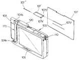
도 1은 본 발명에 의한 휴대용 컴퓨터와 통신기기의 분리 조립 구성도.1 is a separate assembly diagram of a portable computer and a communication device according to the present invention.
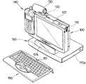
도 2는 본 발명에 의한 휴대용 컴퓨터와 통신기기의 조립 사시도,2 is an assembled perspective view of a portable computer and a communication device according to the present invention;
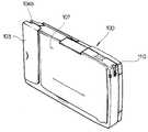
도 3은 도 1에 도시된 휴대용 컴퓨터의 사시도,3 is a perspective view of the portable computer shown in FIG. 1;
도 4 내지 도 5는 도 3에 도시된 휴대용 컴퓨터의 카바의 동작 상태도,4 to 5 is an operating state diagram of the cover of the portable computer shown in FIG.
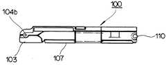
도 6은 휴대용 컴퓨터 카바의 구성도,6 is a block diagram of a portable computer cover,
도 7 내지 도 8은 휴대용 컴퓨터에 통신기기 장착 과정을 나타낸 상태도.7 to 8 are diagrams illustrating a process of mounting a communication device on a portable computer.
* 도면의 주요부분에 대한 부호 설명* Explanation of symbols on the main parts of the drawings
100 : 본체 101 : 장착구100: body 101: mounting holes
104a : 접속부 104b : 힌지104a:
110 : 전자펜 120 : PCMCIA 카드110: electronic pen 120: PCMCIA card
130 : 디지탈 카메라 140 : 통신기기130: digital camera 140: communication device
150 : 스탠드 151 : 마운트부150: stand 151: mount portion
160 : 기보드 170 : 통신기기 장착부160: Gigaboard 170: communication device mounting
상기와 같은 목적을 달성하기 위한 본 발명에 따른 휴대용 컴퓨터는, 휴대용컴퓨터에 있어서, 본체와, 상기 본체의 일측면에 회전 가능하도록 장착되는 뱃터리와, 상기 본체의 일측에 형성되는 힌지와 상기 힌지의 마주하는 곳에 형성되는 수 접속부를 가지는 통신기기 장착부를 포함하는 것으로, 통신기기의 상하단이 상기 힌지와 수접속부에 의해 상기 본체에 고정되도록 된 것을 특징으로 한다.A portable computer according to the present invention for achieving the above object, in the portable computer, a main body, a battery mounted rotatably on one side of the main body, a hinge formed on one side of the main body and the hinge And a communication device mounting part having a male connection part formed at an opposite side of the communication device, wherein the upper and lower ends of the communication device are fixed to the main body by the hinge and the male connection part.
이하, 본 발명의 실시예를 첨부된 도면을 이용하여 살펴보면 다음과 같다.Hereinafter, an embodiment of the present invention will be described with reference to the accompanying drawings.
도 1에서와 같이 본 발명에 의한 통신기기의 장착이 가능한 휴대용 컴퓨터는 본체(100)와, 상기 본체(100)의 일측면에 회전 가능하도록 장착되는 뱃터리(103)와, 상기 본체(100)와 상기 뱃터리(103)에 의해 형성된 면에 통신기기(140)를 장착할 수 있는 통신기기 장착부(170)로 구성된다.As shown in FIG. 1, a portable computer capable of mounting a communication device according to the present invention includes a
보다 구체적으로는, 우측 상부면에 장착구(101)를 형성하고 좌측면에는 수접속부(104a) 및 힌지(104b)를 형성하며 하부면에 접속부(105)를 형성한 본체(100)와, 상기 본체(100)의 케이스의 우측 상부면에 형성된 장착구(101)에 삽입되어 보관되는 전자펜(110)과, 상기 본체(100)의 좌측 하부에 형성된 수접속부(104a)에 장탈착이 가능하도록 암접속부(l41)를 형성하고 좌측 상부에 형성된 힌지(104b)에 장착되도록 장탈착부(142)를 형성한 통신기기(140)로 구성된다.More specifically, the
이러한 구성 중에 상기 통신기기(140)는, 상기 본체(100) 케이스에 장착되는 뱃터리(Battery)(103)를 좌측으로 회전시킨 후 펼쳐진 면으로 형성되는 통신기기 장착부(170)에 지지되도록 장착된다.During this configuration, the
이와 같은 구성을 갖는 본 발명을 첨부된 도면을 이용하여 보다 상세하게 살펴보면 다음과 같다.Looking at the present invention having such a configuration in more detail with reference to the accompanying drawings as follows.
도 2 내지 도 3에서와 같이 본체(100) 케이스의 우측 상부면에 형성된 장착구(101)를 전자펜(110)의 외경 크기에 맞게 형성되어 미사용시 장착 보관되도록 하며, 좌측 상부면에 형성된 접속부(102)에는 PCMCIA 카드(120)가 장탈착이 가능하도록 PCMCIA 카드(120)의 외관 크기에 맞도록 공간을 형성한다.2 to 3, the
PCMCIA 카드(120)가 장착될 공간에는 PCMCIA 카드(120)에서 전송되는 신호를 접속할 수 있도록 코넥터(도시 않음)가 형성되어 PCMCIA 카드(120) 장착과 동시에 발생된 신호를 본체(100)의 내부에 있는 신호처리 회로로 전송될 수 있음은 물론이다.In the space where the PCMCIA
PCMCIA 카드(120)가 본체(100)에 장착된 후 PCMCIA 카드(120)에 형성된 홀(121)에는 디지탈 카메라(130)에 형성된 힌지(131)가 장착되며, PCMCIA 카드(120)에 디지탈 카메라(130)의 장착과 동시에 힌지(131)를 중심으로 상하·좌우로 회전가능하게 된다. 그리고 버튼(132)은 디지탈 카메라(130)의 줌 인/아웃(Zoomin/out) 기능을 조절시 사용된다·After the PCMCIA
PCMCIA 카드(120)에 형성된 흘(121)에 디지탈 카메라(130)가 장착되면, 디지탈 카메라(130)에 의해 발생된 신호는 케이블(133)을 통해서 PCMCIA 카드(120)로전송되어 본체(100)로 전송된다.When the
본체(1OO)로 전송된 신호는 유저에 의해 다양한 어플리케이션(Application)프로그램을 통해서 편집될 수 있다. 즉 전자펜(110)을 이용하여 어플리케이션 프로그램을 선택한 후 디지탈 카메라(130)로부터 전송된 신호에 따른 데이터를 편집하여 저장할 수 있게 된다. 또한, 편집된 데이터를 인쇄하기 위해 준비된 프린터 코넥터(모시 않음)를 프린터 코넥터 카바(107)에 의해 보호될 수 있도록 하였다.The signal transmitted to the
그리고, 본체(100) 케이스의 좌측에는 힌지(104b)를 중심으로 뱃터리(103)가 회전가능하도록 결착된다. 이 때 힌지(104b)를 중심으로 뱃터리(103)가 회전되어펼쳐지면 뱃터리(103)의 노츨면과 본체(100)의 일면에 의해 통신기기 장착부(170)가 형성된다.Then, the
따라서 통신기기(140)를 장착하기 위해서 뱃터리(103)를 본체(100) 외측으로회전시키면 통신기기 장착부(170)가 형성되고, 이 통신기기 장착부(170)에 통신기기(140)를 밀착시켜 장착하게 된다.Accordingly, when the
뱃터리(103)를 회전이동시킨 후 디지탈 통신기기(140)의 하부면 내측으로 형성된 암접속부(141)를 본체(100) 케이스의 좌측 하부에 형성된 수접속부(104a)에 장착한다. 이와 동시에 디지탈 통신기기(140)에 형성된 장탈착부(142)를 본체(100)의 좌측 상부에 형성된 힌지(104b)에 일정한 압력을 가해 장착시킨다.After rotating the
즉, 통신기기(140)는, 본체(100) 케이스에 장착된 뱃터리(Battery)(103)를 좌측으로 회전시킨 후 펼쳐진 면적인 통신기기 장착부(170)에 지지되도록 부착되며, 장탈착부(142)는 힌지(104)의 외관크기 보다 적어도 같거나 작은 홈으로 형성하여 힌지(104)에 억지 끼워맞춤 되도록 하여 이탈을 방지한다.That is, the
보다 구체적으로, 본체(100) 케이스 하부면에 형성된 암접속부(105)를 스탠드(150)의 마운트부(151) 상에 형성된 수접속부(152)에 장착한다. 본체(100)가 수접속부(152)에 장착됨과 동시에 수접속부(152) 내측에 형성된 신호 접속용 코넥터(152a)가 본체(100) 하부면에 형성된 암접속부(l05)의 내측에 형성된 코넥터(도시 않음)와 접속된다.More specifically, the female connecting
이와 같이 본체(100)가 스탠드(150)에 장착되면 스탠드(150)의 마운트(151)에 형성된 수광부(151a)로 전송된 신호를 스탠드(150)의 내부 회로를 통해서 본체(100)로 전송된다.When the
이 때 수광부(151a)는 키보드(16)의 IR 발광부(161)에서 발생된 IR를 전송받아 전기적 신호로 변환하여 본체(100)로 전송한다. 그리고, 키보드(160)에 형성된 받침대(162)는, 스탠드(150)의 마운트(151)에 형성된 수광부(151a)로 정확하게 IR를 전송하도록 일정한 각도로 형성됨은 물론이다.At this time, the
또한 스탠드(150)의 우측면에 형성된 주변장치 장탈착부(153)는, 보조 주변장치인 DVDP(170a) 내지는 FPD(도시 않음)를 장착 및 탈착하여 교체하여 사용될 수있도록 한다. 이러한 과정을 통해서 본체(100)에 통신기기(140)이 장착된 상태는 도 2에 나타낸다.In addition, the peripheral device mounting and detaching
보다 구체적으로 본체(100)에 통신기기(140)를 장착하는 과정을 첨부된 도면을 이용하여 살펴보면 다음과 같다.More specifically, the process of mounting the
먼저 도 3 내지 도 4는 본체(100)의 미사용시 카바(107)와 뱃터리(103)와 장착상태를 나타낸다. 이 상태에서 본체(100)를 사용하기 위해 카바(107)를 도 5에서와 같은 방향으로 열게 된다.First, FIGS. 3 to 4 show mounting states of the
이 때 카바(107)는 2절 힌지(107')에 의해 본체(100)의 상부면에 장착된다.At this time, the
2절 힌지(107')는 도 6에서와 같이 제1고정홀(107a')과 제1고정핀(107a") 및제2고정홀(107b')과 제2고정핀(107b")으로 구성된다. 그리고, 제 2 고정핀(107b")에 의해 2절 힌지(107')가 본체(100)의 상부면에 고정된다.Section 2 hinge 107 'is composed of a
이로 인해서 카바(107)를 수직 방향으로 열게 되며 먼저 제1고정홀(107a')과 제1고정핀(107a")에 의해 힌지(107')가 카바(107)와 수평방향으로 펼친 후, 다시 카바(107)를 본체(100)의 뒷면으로 회전시키면 제2고정홀(107b')과 제2고 정핀(107b")에 의해 카바(107)가 뒤면에 밀착된 상태를 유지시켜 준다.Due to this, the
이 과정을 통해서 본체(100)의 카바(107)가 열리면 도 8에서와 같이 본체(100)에 통신기기(140)를 장착하게 된다. 즉, 다음 뱃터리(103)를 힌지(104b)를 중심으로 회전시켜 좌측방향으로 펼쳐 통신기기 장착부(170)를 형성한다.When the
뱃터리(103)가 펼쳐져 통신기기 장착부(170)가 형성되면, 통신기기(140)의 하부면 내측으로 형성된 암접속부(141)를 본체(100)의 좌측 하부에 형성된 수접속부(104a)에 장착하고, 동시에 통신기기(140)에 형성된 장탈착부(142)를 본체(100)의 좌측 상부에 형성된 힌지(104b)에 일정한 압력을 가해 장착시킨다.When the
이상과 같은 과정을 통해서 장착된 통신기기(140)는 장착의 역순서를 통해서 탈착이 가능하다.The
이상에서 설명한 바와 같이 본 발명은, 휴대용 컴퓨터에 통신기기을 장착함으로써 휴대용 컴퓨터 사용시 통신기기를 보다 용이하게 관리 사용할 수 있는 효과가 있다.As described above, the present invention has an effect of more easily managing and using a communication device when using a portable computer by attaching the communication device to the portable computer.
Claims (2)
Translated fromKoreanPriority Applications (2)
| Application Number | Priority Date | Filing Date | Title |
|---|---|---|---|
| KR1019970052251AKR100303081B1 (en) | 1997-10-13 | 1997-10-13 | Portable computer for mounting communication devices |
| US09/170,290US6049450A (en) | 1997-10-13 | 1998-10-13 | Portable computer on which a communication device can be mounted |
Applications Claiming Priority (1)
| Application Number | Priority Date | Filing Date | Title |
|---|---|---|---|
| KR1019970052251AKR100303081B1 (en) | 1997-10-13 | 1997-10-13 | Portable computer for mounting communication devices |
Publications (2)
| Publication Number | Publication Date |
|---|---|
| KR19990031489A KR19990031489A (en) | 1999-05-06 |
| KR100303081B1true KR100303081B1 (en) | 2001-11-22 |
Family
ID=19522596
Family Applications (1)
| Application Number | Title | Priority Date | Filing Date |
|---|---|---|---|
| KR1019970052251AExpired - Fee RelatedKR100303081B1 (en) | 1997-10-13 | 1997-10-13 | Portable computer for mounting communication devices |
Country Status (2)
| Country | Link |
|---|---|
| US (1) | US6049450A (en) |
| KR (1) | KR100303081B1 (en) |
Families Citing this family (69)
| Publication number | Priority date | Publication date | Assignee | Title |
|---|---|---|---|---|
| GB9603582D0 (en) | 1996-02-20 | 1996-04-17 | Hewlett Packard Co | Method of accessing service resource items that are for use in a telecommunications system |
| US6786420B1 (en) | 1997-07-15 | 2004-09-07 | Silverbrook Research Pty. Ltd. | Data distribution mechanism in the form of ink dots on cards |
| US6618117B2 (en) | 1997-07-12 | 2003-09-09 | Silverbrook Research Pty Ltd | Image sensing apparatus including a microcontroller |
| US6690419B1 (en) | 1997-07-15 | 2004-02-10 | Silverbrook Research Pty Ltd | Utilising eye detection methods for image processing in a digital image camera |
| US7110024B1 (en) | 1997-07-15 | 2006-09-19 | Silverbrook Research Pty Ltd | Digital camera system having motion deblurring means |
| US6879341B1 (en) | 1997-07-15 | 2005-04-12 | Silverbrook Research Pty Ltd | Digital camera system containing a VLIW vector processor |
| US7551201B2 (en) | 1997-07-15 | 2009-06-23 | Silverbrook Research Pty Ltd | Image capture and processing device for a print on demand digital camera system |
| US6624848B1 (en) | 1997-07-15 | 2003-09-23 | Silverbrook Research Pty Ltd | Cascading image modification using multiple digital cameras incorporating image processing |
| AUPP702098A0 (en)* | 1998-11-09 | 1998-12-03 | Silverbrook Research Pty Ltd | Image creation method and apparatus (ART73) |
| AUPP701798A0 (en)* | 1998-11-09 | 1998-12-03 | Silverbrook Research Pty Ltd | Image creation method and apparatus (ART75) |
| AUPP702198A0 (en)* | 1998-11-09 | 1998-12-03 | Silverbrook Research Pty Ltd | Image creation method and apparatus (ART79) |
| US7118481B2 (en)* | 1998-11-09 | 2006-10-10 | Silverbrook Research Pty Ltd | Video gaming with integral printer device |
| JP3540187B2 (en)* | 1999-02-25 | 2004-07-07 | シャープ株式会社 | Display device |
| US6144552A (en)* | 1999-04-26 | 2000-11-07 | Emc Corporation | Handheld computer system |
| AUPQ056099A0 (en) | 1999-05-25 | 1999-06-17 | Silverbrook Research Pty Ltd | A method and apparatus (pprint01) |
| US6219227B1 (en)* | 1999-07-27 | 2001-04-17 | David Trane | Portable computer assembly |
| AU143402S (en) | 1999-12-22 | 2001-04-06 | Sharp Kk | Electronic computer with camera |
| US6262884B1 (en)* | 2000-02-02 | 2001-07-17 | Wayne Hwang | Portable computer inherently carried with overhead projection device |
| US6545862B1 (en)* | 2000-05-25 | 2003-04-08 | Palm, Inc. | Method and system for an interchangeable modular display screen for a portable computing device |
| KR20020001107A (en)* | 2000-06-26 | 2002-01-09 | 이형도 | Video camera for computer |
| US6525928B1 (en)* | 2000-09-20 | 2003-02-25 | 3Com Corporation | Case with communication module having a latching connector for a handheld computer system |
| US6717801B1 (en)* | 2000-09-29 | 2004-04-06 | Hewlett-Packard Development Company, L.P. | Standardized RF module insert for a portable electronic processing device |
| JP2002108504A (en)* | 2000-10-02 | 2002-04-12 | Toshiba Corp | Information processing device |
| CA2357236C (en)* | 2000-10-17 | 2011-09-06 | Spx Development Corporation | Plug-in module for portable computing device |
| EP1339232B1 (en)* | 2000-11-30 | 2008-08-13 | Sony Corporation | Monitor device, base device and information terminal device |
| US6496365B2 (en)* | 2001-04-13 | 2002-12-17 | Huo-Lu Tsai | Input apparatus for wireless communications with a portable computerized apparatus |
| JP2003008736A (en)* | 2001-06-22 | 2003-01-10 | Pioneer Electronic Corp | Portable information terminal |
| JP2003029870A (en)* | 2001-07-12 | 2003-01-31 | Toshiba Corp | Portable information terminal |
| US6930655B2 (en)* | 2001-07-31 | 2005-08-16 | Koninklijke Philips Electronics N.V. | Display monitor has stand-alone mode and PC peripheral mode |
| US6859358B2 (en)* | 2001-09-14 | 2005-02-22 | International Business Machines Corporation | Sub-notebook portable computer with integrated wireless mobile telephone |
| US6757156B2 (en)* | 2002-03-06 | 2004-06-29 | Xybernaut Corporation | Ergonomic hand held display |
| US8780282B2 (en)* | 2003-11-07 | 2014-07-15 | Voxx International Corporation | Vehicle entertainment system |
| US20050235327A1 (en)* | 2003-11-07 | 2005-10-20 | Vitito Christopher J | Vehicle entertainment system |
| US20060070103A1 (en)* | 2003-11-07 | 2006-03-30 | Vitito Christopher J | Vehicle entertainment system |
| US20050235326A1 (en)* | 2003-11-07 | 2005-10-20 | Vitito Christopher J | Vehicle entertainment system |
| US7604273B2 (en)* | 2003-11-07 | 2009-10-20 | Vitito Christopher J | Vehicle entertainment system |
| US20050099547A1 (en)* | 2003-11-07 | 2005-05-12 | Vitito Christopher J. | Automobile entertainment system |
| US20050223406A1 (en)* | 2003-11-07 | 2005-10-06 | Vitito Christopher J | Vehicle entertainment system including a detachable video system with a hard drive based video source |
| US20050198152A1 (en)* | 2004-02-12 | 2005-09-08 | International Business Machines Corporation | Computer with a personal digital assistant |
| US7403377B2 (en)* | 2005-01-20 | 2008-07-22 | Hewlett-Packard Development Company, L.P. | Method of manufacture and an enclosure for a display for an electronic device |
| US7857382B2 (en)* | 2005-04-20 | 2010-12-28 | Audiovox Corporation | Detachable vehicle entertainment system for the armrest/console of a vehicle |
| US8070224B2 (en)* | 2005-04-20 | 2011-12-06 | Audiovox Corporation | Vehicle entertainment system incorporated within the armrest/console of a vehicle |
| US8120716B2 (en)* | 2005-06-16 | 2012-02-21 | Audiovox Corporation | Vehicle entertainment system including monitor for rear view enhancement |
| WO2006138446A2 (en)* | 2005-06-16 | 2006-12-28 | Vitito Christopher J | Vehicle entertainment system |
| US8034153B2 (en)* | 2005-12-22 | 2011-10-11 | Momentive Performances Materials, Inc. | Wear resistant low friction coating composition, coated components, and method for coating thereof |
| TW200738031A (en)* | 2006-03-21 | 2007-10-01 | Asustek Comp Inc | Audio-video device |
| US9384672B1 (en) | 2006-03-29 | 2016-07-05 | Amazon Technologies, Inc. | Handheld electronic book reader device having asymmetrical shape |
| US8413904B1 (en) | 2006-03-29 | 2013-04-09 | Gregg E. Zehr | Keyboard layout for handheld electronic book reader device |
| US7748634B1 (en) | 2006-03-29 | 2010-07-06 | Amazon Technologies, Inc. | Handheld electronic book reader device having dual displays |
| CN100520677C (en)* | 2006-10-12 | 2009-07-29 | 英业达股份有限公司 | Portable electronic device |
| USD563920S1 (en) | 2007-04-23 | 2008-03-11 | Vitito Christopher J | Portable entertainment system |
| USD561139S1 (en) | 2007-04-23 | 2008-02-05 | Vitito Christopher J | Portable entertainment system |
| US7751183B2 (en)* | 2007-12-14 | 2010-07-06 | Harris Technology, Llc | USB stacking devices and applications |
| TW200942143A (en)* | 2008-03-19 | 2009-10-01 | Micro Star Int Co Ltd | Electronic device structure |
| TW200942952A (en)* | 2008-04-09 | 2009-10-16 | Compal Electronics Inc | Portable electronic device with projection function |
| US8760856B2 (en) | 2008-05-09 | 2014-06-24 | Gary A. Janz | Combination support base and printer for portable computers |
| US7738238B2 (en)* | 2008-10-03 | 2010-06-15 | Keng-Yuan Liu | Portable audio/video playing device disposing structure |
| US8238538B2 (en) | 2009-05-28 | 2012-08-07 | Comcast Cable Communications, Llc | Stateful home phone service |
| US20110043579A1 (en)* | 2009-08-24 | 2011-02-24 | Frank Leppanen | Combination laptop computer and printer |
| US8471824B2 (en)* | 2009-09-02 | 2013-06-25 | Amazon Technologies, Inc. | Touch-screen user interface |
| US8451238B2 (en) | 2009-09-02 | 2013-05-28 | Amazon Technologies, Inc. | Touch-screen user interface |
| US9262063B2 (en)* | 2009-09-02 | 2016-02-16 | Amazon Technologies, Inc. | Touch-screen user interface |
| US8624851B2 (en)* | 2009-09-02 | 2014-01-07 | Amazon Technologies, Inc. | Touch-screen user interface |
| USD641350S1 (en)* | 2009-12-19 | 2011-07-12 | DanMedical Ltd. | Base for a portable medical device or laptop |
| USD644228S1 (en)* | 2010-06-24 | 2011-08-30 | Savant Systems Llc | In-wall iPad dock |
| USD644229S1 (en)* | 2010-06-24 | 2011-08-30 | Savant Systems Llc | In-wall iPod dock |
| USD651605S1 (en)* | 2011-02-02 | 2012-01-03 | Patrick Bouaziz | Cradle for a portable device |
| USD660840S1 (en)* | 2011-02-28 | 2012-05-29 | Kuo Hsiung Chen | Vehicle mounted docking station for electronic device |
| US9204723B2 (en) | 2014-04-15 | 2015-12-08 | Target Brands, Inc. | Accessories support bracket |
Citations (1)
| Publication number | Priority date | Publication date | Assignee | Title |
|---|---|---|---|---|
| JPH06301445A (en)* | 1993-04-09 | 1994-10-28 | Citizen Watch Co Ltd | Portable computer |
Family Cites Families (12)
| Publication number | Priority date | Publication date | Assignee | Title |
|---|---|---|---|---|
| US4825395A (en)* | 1986-05-29 | 1989-04-25 | Hewlett-Packard Company | Apparatus with torsionally stressed conductors routed through a hollow articulated hinge |
| US4878293A (en)* | 1986-05-29 | 1989-11-07 | Hewlett-Packard Company | Method of interconnecting assemblies using torsionly stressed conductors routed through a hollow articulated hinge |
| JP2663591B2 (en)* | 1988-12-12 | 1997-10-15 | 日本電気株式会社 | Rotating section connection structure |
| US5193069A (en)* | 1989-04-28 | 1993-03-09 | Kabushiki Kaisha Toshiba | Portable computer to which different types of flat display panels can be attached |
| US5020090A (en)* | 1989-11-13 | 1991-05-28 | Intelligence Technology Corporation | Apparatus for removably connecting a cellular portable telephone to a computer |
| US5268817A (en)* | 1990-04-27 | 1993-12-07 | Kabushiki Kaisha Toshiba | Portable computer with keyboard and having display with coordinate input tablet rotatably mounted to face either toward or away from keyboard when closed over keyboard |
| JP2730810B2 (en)* | 1991-05-10 | 1998-03-25 | シャープ株式会社 | Information processing device |
| WO1994023476A1 (en)* | 1993-03-26 | 1994-10-13 | Zaidan Khalil S | Hinge assembly for electronic devices |
| US5517387A (en)* | 1994-04-29 | 1996-05-14 | Ast Research, Inc. | Selectively engageable interface for circuit cards |
| US5583744A (en)* | 1994-09-06 | 1996-12-10 | Citizen Watch Co., Ltd. | Portable computer with detachable battery pack |
| US5619395A (en)* | 1995-04-25 | 1997-04-08 | Mcbride; Jon | Device for attaching a wireless telephone to a portable computer |
| US5850998A (en)* | 1996-04-02 | 1998-12-22 | Apple Computer, Inc. | Method and apparatus for mounting an accessory on an appliance |
- 1997
- 1997-10-13KRKR1019970052251Apatent/KR100303081B1/ennot_activeExpired - Fee Related
- 1998
- 1998-10-13USUS09/170,290patent/US6049450A/ennot_activeExpired - Fee Related
Patent Citations (1)
| Publication number | Priority date | Publication date | Assignee | Title |
|---|---|---|---|---|
| JPH06301445A (en)* | 1993-04-09 | 1994-10-28 | Citizen Watch Co Ltd | Portable computer |
Also Published As
| Publication number | Publication date |
|---|---|
| US6049450A (en) | 2000-04-11 |
| KR19990031489A (en) | 1999-05-06 |
Similar Documents
| Publication | Publication Date | Title |
|---|---|---|
| KR100303081B1 (en) | Portable computer for mounting communication devices | |
| KR100303082B1 (en) | Multimedia device using portable computer | |
| US7065381B2 (en) | Personal communicator | |
| US6646672B2 (en) | Pocket video conference computer | |
| US20040114319A1 (en) | User friendly monitor unit setting base with slidable keyboard | |
| US6672558B2 (en) | Holding apparatus for information input devices | |
| KR20040079134A (en) | Desk top charger for bar type portable wireless terminal | |
| JP2003140770A (en) | Computer device, function extending pad, mouse cradle, and function extending pad connecting unit | |
| US20060098116A1 (en) | Digital camera having alternate functional covers | |
| CN100450332C (en) | Interface connector cover opening and closing device for mobile communication terminal | |
| US20040066616A1 (en) | Personal digital assistant assembly | |
| US20040253132A1 (en) | Cradle for portable communication device | |
| KR100677301B1 (en) | Handheld terminal | |
| JP3718443B2 (en) | Attached equipment | |
| KR100402793B1 (en) | Portable terminal having a keyboard | |
| CN222954218U (en) | Electronic equipment protective housing | |
| JP3621548B2 (en) | Electronics | |
| KR19990031490A (en) | Portable computer with removable digital camera | |
| KR20030028943A (en) | Case of portable terminal having keyboard | |
| JP2006115543A (en) | Imaging apparatus | |
| JP3086581U (en) | Mobile phone holder for personal computers and portable digital devices | |
| CN206759517U (en) | A modular smartphone case | |
| KR19990000117U (en) | Portable computer with slide camera | |
| KR20040079599A (en) | Mouse connectable with other equipment | |
| KR19980050336U (en) | CCD camera unit mounted on top of notebook PC and monitor |
Legal Events
| Date | Code | Title | Description |
|---|---|---|---|
| A201 | Request for examination | ||
| PA0109 | Patent application | St.27 status event code:A-0-1-A10-A12-nap-PA0109 | |
| PA0201 | Request for examination | St.27 status event code:A-1-2-D10-D11-exm-PA0201 | |
| R17-X000 | Change to representative recorded | St.27 status event code:A-3-3-R10-R17-oth-X000 | |
| R18-X000 | Changes to party contact information recorded | St.27 status event code:A-3-3-R10-R18-oth-X000 | |
| PN2301 | Change of applicant | St.27 status event code:A-3-3-R10-R13-asn-PN2301 St.27 status event code:A-3-3-R10-R11-asn-PN2301 | |
| PG1501 | Laying open of application | St.27 status event code:A-1-1-Q10-Q12-nap-PG1501 | |
| PN2301 | Change of applicant | St.27 status event code:A-3-3-R10-R13-asn-PN2301 St.27 status event code:A-3-3-R10-R11-asn-PN2301 | |
| E902 | Notification of reason for refusal | ||
| PE0902 | Notice of grounds for rejection | St.27 status event code:A-1-2-D10-D21-exm-PE0902 | |
| T11-X000 | Administrative time limit extension requested | St.27 status event code:U-3-3-T10-T11-oth-X000 | |
| R18-X000 | Changes to party contact information recorded | St.27 status event code:A-3-3-R10-R18-oth-X000 | |
| T11-X000 | Administrative time limit extension requested | St.27 status event code:U-3-3-T10-T11-oth-X000 | |
| T11-X000 | Administrative time limit extension requested | St.27 status event code:U-3-3-T10-T11-oth-X000 | |
| P11-X000 | Amendment of application requested | St.27 status event code:A-2-2-P10-P11-nap-X000 | |
| P13-X000 | Application amended | St.27 status event code:A-2-2-P10-P13-nap-X000 | |
| E701 | Decision to grant or registration of patent right | ||
| PE0701 | Decision of registration | St.27 status event code:A-1-2-D10-D22-exm-PE0701 | |
| GRNT | Written decision to grant | ||
| PR0701 | Registration of establishment | St.27 status event code:A-2-4-F10-F11-exm-PR0701 | |
| PR1002 | Payment of registration fee | St.27 status event code:A-2-2-U10-U11-oth-PR1002 Fee payment year number:1 | |
| PG1601 | Publication of registration | St.27 status event code:A-4-4-Q10-Q13-nap-PG1601 | |
| PN2301 | Change of applicant | St.27 status event code:A-5-5-R10-R13-asn-PN2301 St.27 status event code:A-5-5-R10-R11-asn-PN2301 | |
| R18-X000 | Changes to party contact information recorded | St.27 status event code:A-5-5-R10-R18-oth-X000 | |
| R18-X000 | Changes to party contact information recorded | St.27 status event code:A-5-5-R10-R18-oth-X000 | |
| R18-X000 | Changes to party contact information recorded | St.27 status event code:A-5-5-R10-R18-oth-X000 | |
| PR1001 | Payment of annual fee | St.27 status event code:A-4-4-U10-U11-oth-PR1001 Fee payment year number:4 | |
| PR1001 | Payment of annual fee | St.27 status event code:A-4-4-U10-U11-oth-PR1001 Fee payment year number:5 | |
| PN2301 | Change of applicant | St.27 status event code:A-5-5-R10-R13-asn-PN2301 St.27 status event code:A-5-5-R10-R11-asn-PN2301 | |
| PN2301 | Change of applicant | St.27 status event code:A-5-5-R10-R13-asn-PN2301 St.27 status event code:A-5-5-R10-R11-asn-PN2301 | |
| PR1001 | Payment of annual fee | St.27 status event code:A-4-4-U10-U11-oth-PR1001 Fee payment year number:6 | |
| PR1001 | Payment of annual fee | St.27 status event code:A-4-4-U10-U11-oth-PR1001 Fee payment year number:7 | |
| FPAY | Annual fee payment | Payment date:20080604 Year of fee payment:8 | |
| PR1001 | Payment of annual fee | St.27 status event code:A-4-4-U10-U11-oth-PR1001 Fee payment year number:8 | |
| LAPS | Lapse due to unpaid annual fee | ||
| PC1903 | Unpaid annual fee | St.27 status event code:A-4-4-U10-U13-oth-PC1903 Not in force date:20090710 Payment event data comment text:Termination Category : DEFAULT_OF_REGISTRATION_FEE | |
| PC1903 | Unpaid annual fee | St.27 status event code:N-4-6-H10-H13-oth-PC1903 Ip right cessation event data comment text:Termination Category : DEFAULT_OF_REGISTRATION_FEE Not in force date:20090710 | |
| R18-X000 | Changes to party contact information recorded | St.27 status event code:A-5-5-R10-R18-oth-X000 |