KR100287611B1 - Pedometer - Google Patents
PedometerDownload PDFInfo
- Publication number
- KR100287611B1 KR100287611B1KR1019970703112AKR19970703112AKR100287611B1KR 100287611 B1KR100287611 B1KR 100287611B1KR 1019970703112 AKR1019970703112 AKR 1019970703112AKR 19970703112 AKR19970703112 AKR 19970703112AKR 100287611 B1KR100287611 B1KR 100287611B1
- Authority
- KR
- South Korea
- Prior art keywords
- main body
- sensor
- angle
- detection sensor
- angle detection
- Prior art date
- Legal status (The legal status is an assumption and is not a legal conclusion. Google has not performed a legal analysis and makes no representation as to the accuracy of the status listed.)
- Expired - Fee Related
Links
Images


Classifications
- G—PHYSICS
- G06—COMPUTING OR CALCULATING; COUNTING
- G06M—COUNTING MECHANISMS; COUNTING OF OBJECTS NOT OTHERWISE PROVIDED FOR
- G06M7/00—Counting of objects carried by a conveyor
- G—PHYSICS
- G01—MEASURING; TESTING
- G01C—MEASURING DISTANCES, LEVELS OR BEARINGS; SURVEYING; NAVIGATION; GYROSCOPIC INSTRUMENTS; PHOTOGRAMMETRY OR VIDEOGRAMMETRY
- G01C22/00—Measuring distance traversed on the ground by vehicles, persons, animals or other moving solid bodies, e.g. using odometers, using pedometers
- G01C22/006—Pedometers
Landscapes
- Physics & Mathematics (AREA)
- Engineering & Computer Science (AREA)
- General Physics & Mathematics (AREA)
- Radar, Positioning & Navigation (AREA)
- Remote Sensing (AREA)
- Theoretical Computer Science (AREA)
- Measurement Of Distances Traversed OnThe Ground (AREA)
- Measurement Of The Respiration, Hearing Ability, Form, And Blood Characteristics Of Living Organisms (AREA)
Abstract
Translated fromKoreanDescription
Translated fromKorean일반적으로 보수계는 본체와, 이 본체에 설치되어 신체의 움직임에 의한 걸음수 신호를 검출하는 가속도 센서와, 이 가속도 센서의 출력에 근거하여 걸음수를 계수하는 걸음수 계수기를 구비하여, 보행(또는 주행)에 따른 신체의 움직임(상하 움직임)으로부터 걸음수를 계측한다.In general, a pedometer includes a main body, an acceleration sensor provided in the main body to detect a step signal caused by movement of the body, and a step counter that counts the number of steps based on the output of the acceleration sensor. The number of steps is measured from the body movement (up and down movement) according to the running.
그런데, 상하 움직임을 검출하는 경우, 보행 장소의 상태, 착용한 신발, 보행 방법 등에 따라, 상향 이동과 하향 이동은 각각 크게 변화한다. 따라서, 상향 이동과 하향 이동 중 어느 한쪽에 대응하는 출력만을 검출하여 걸음수를 계수하는 종래의 보수계로는 걸음수를 정확하게 측정할 수 없다고 하는 문제점이 있다.By the way, when the up and down movement is detected, the upward movement and the downward movement vary greatly according to the state of the walking place, worn shoes, the walking method, and the like. Therefore, there is a problem in that the number of steps cannot be accurately measured with a conventional pedometer that detects only an output corresponding to either one of the upward and downward motions and counts the number of steps.
이 문제점을 해결하기 위해서, 예컨대 일본 특허 공개 평2 - 161932호(이하, 제1 선행 기술이라 한다)에 기재된 「보수계」는 상향의 가속도와 하향의 가속도를 각각 검출하는 상검출부 및 하검출부와, 상·하 검출부 중 어디에서 발생하는 보행 신호를 계수의 대상으로 할 것인가를 선택하는 선택부를 구비하여, 보행 장소, 신발, 걷는 방법 등에 상관 없이 걸음수를 정확하게 측정할 수 있도록 하고 있다.In order to solve this problem, for example, the "pedometer" described in Japanese Patent Application Laid-Open No. Hei 2-161932 (hereinafter referred to as "first prior art") includes an upper detection section and a lower detection section that detect upward acceleration and downward acceleration, respectively; A selector for selecting a walking signal generated from an upper / lower detection part as a target of counting is provided, so that the number of steps can be accurately measured regardless of the walking place, shoes, walking method, or the like.
한편, 예컨대 일본 특허 공개 평1 - 287417호(이하, 제2 선행 기술이라 한다)에 기재된 「보수계」는 캔틸레버식 지지 구조로 형성된 압전 소자를 센서로 하여, 이 센서의 자유단에는 추가 있어서, 고정단이 충격 완충 부재를 매개로 지지된 가속도 센서를 사용하고 있다.On the other hand, for example, the "pedometer" described in Japanese Patent Laid-Open No. Hei-287417 (hereinafter referred to as the second prior art) uses a piezoelectric element formed of a cantilevered support structure as a sensor, and is further fixed to the free end of the sensor. The stage uses the acceleration sensor supported by the shock buffer member.
그러나, 상기 제1 선행 기술에 기재된 보수계를 포함한 종래의 보수계는 모두 가속도 센서를 내장하는 보수계 본체를 바지나 스커트의 벨트 등에 장착하여 걸음수를 계측하는 것이기 때문에, 벨트가 불필요한 복장에서는 본체를 장착할 수 없어서, 걸음수를 측정할 수 없다고 하는 문제점이 있다. 또, 본체를 벨트에 장착하더라도, 보수계는 어느 정도의 크기나 두께를 지니는 것이므로, 보수계가 눈에 띄어서, 걸음수를 측정하고 있는 것이 남들이 알기 쉬울 뿐만 아니라, 보수계를 옷으로 덮어서 숨겼다고 하더라도, 보수계 부분이 불거지거나 하여 외관이 나쁘게 된다고 하는 문제점이 있다.However, all conventional pedometers, including the pedometer described in the first prior art, are equipped with a pedometer body having an accelerometer attached to a belt of a pants or a skirt, and the like to measure the number of steps. There is a problem that it is impossible to measure the number of steps. In addition, even if the body is attached to the belt, the pedometer has a certain size and thickness, so that the pedometer is noticeable and it is easy for others to measure the number of steps, and even if the pedometer is covered with clothing, There is a problem that the appearance of the pedometer becomes bad due to bulging.
한편, 상기 제2 선행 기술에 기재된 것과 같은 보수계에서는 추와 압전 소자를 추 케이스에 접착할 필요가 있기 때문에, 조립이 곤란하고, 가공 비용이 많이 드는 문제점이 있다. 또, 복수의 가상축 방향의 검출이 필요한 경우, 같은 가속도 센서를 각각의 축방향으로 각각 개별적으로 배치할 필요가 있기 때문에, 비용이 많이 든다고 하는 문제점이 있다.On the other hand, in the pedometer as described in the second prior art, it is necessary to adhere the weight and the piezoelectric element to the weight case, so that assembly is difficult and processing costs are high. In addition, when the detection of a plurality of virtual axis directions is required, the same acceleration sensor needs to be individually disposed in each of the axial directions, which causes a problem of high cost.
본 발명은 이러한 문제점에 착안하여 이루어진 것으로, 벨트에 장착하지 않더라도 걸음수를 계측할 수 있으며, 더구나 조립이 용이하여, 비용을 삭감할 수 있는 보수계를 제공하는 것을 목적으로 한다.SUMMARY OF THE INVENTION The present invention has been made in view of the above problems, and an object of the present invention is to provide a pedometer capable of measuring the number of steps even if it is not mounted on a belt, and furthermore, it is easy to assemble and reduce costs.
본 발명의 다른 목적은 본체의 각도에 상관 없이, 걸음수 등을 정확하게 검출할 수 있는 보수계를 제공하는 것이다.Another object of the present invention is to provide a pedometer capable of accurately detecting the number of steps and the like regardless of the angle of the main body.
본 발명의 또 다른 목적은 넓은 용도를 갖는 높은 정밀도의 각도 검출 센서 및 이 각도 검출 센서를 구비한 각도 검출 장치를 제공하는 것이다.It is still another object of the present invention to provide a high precision angle detecting sensor having a wide use and an angle detecting device having the angle detecting sensor.
본 발명은 보행이나 주행시의 신체의 움직임에 근거하여 걸음수를 계측하는 보수계에 관한 것으로, 특히 본체의 각도에 상관 없이 걸음수 등을 정확하게 검출할 수 있는 보수계(pedometer)에 관한 것이다.BACKGROUND OF THE
도 1은 본 발명의 제1 실시 형태에 따른 보수계 본체의 내부 구조를 도시한 도면.BRIEF DESCRIPTION OF THE DRAWINGS The figure which shows the internal structure of the pedometer main body which concerns on 1st Embodiment of this invention.
도 2는 제1 실시 형태에 따른 보수계의 구성을 나타내는 블럭도.2 is a block diagram showing a configuration of a pedometer according to a first embodiment.
도 3a 및 도 3b는 제2 실시 형태에 따른 보수계에 있어서의 가속도 센서의 외관 사시도 및 측면도.3A and 3B are an external perspective view and a side view of an acceleration sensor in the pedometer according to the second embodiment.
도 4는 도 3의 가속도 센서의 분해 사시도.4 is an exploded perspective view of the acceleration sensor of FIG. 3.
도 5는 도 3에 나타낸 가속도 센서를 보수계 본체에 내장한 상태를 도시한 도면.5 is a view showing a state in which the accelerometer shown in FIG. 3 is built into the pedometer body;
도 6은 2개의 가속도 센서를 일체화하여 구성한 가속도 센서를 도시한 도면.FIG. 6 is a diagram illustrating an acceleration sensor configured by integrating two acceleration sensors. FIG.
도 7은 제3 실시 형태에 따른 보수계에 있어서의 가속도 센서의 외관 사시도.7 is an external perspective view of an acceleration sensor in the pedometer according to the third embodiment.
도 8은 도 7에 나타낸 가속도 센서를 보수계 본체에 내장한 상태를 도시한 도면.8 is a view showing a state in which the accelerometer shown in FIG. 7 is built into the pedometer body;
도 9는 제1 실시 형태에 따른 보수계에 있어서의 각도 검출 센서의 형태예와 그 작용을 설명하기 위한 도면.9 is a diagram for explaining a form example of an angle detection sensor in the pedometer according to the first embodiment and its operation.
도 10은 제1 실시 형태에 따른 보수계에 있어서의 각도 검출 센서에 관련한 아날로그 회로의 일례를 나타내는 회로도.10 is a circuit diagram showing an example of an analog circuit relating to an angle detection sensor in a pedometer according to the first embodiment.
도 11은 제1 실시 형태에 따른 보수계에 있어서의 각도 검출 센서에 관련된 아날로그 회로의 별도의 예를 나타내는 회로도.11 is a circuit diagram showing another example of an analog circuit related to an angle detection sensor in a pedometer according to a first embodiment.
도 12 및 도 13은 제1 실시 형태에 따른 보수계의 각도 검출 처리 동작의 일례를 나타내는 흐름도.12 and 13 are flowcharts showing an example of the angle detection processing operation of the pedometer according to the first embodiment.
도 14는 제1 실시 형태에 따른 보수계의 각도 검출 처리의 타이밍도.14 is a timing diagram of angle detection processing of a pedometer according to the first embodiment;
도 15a 내지 도 15d는 제4 실시예에 따른 각도 검출 센서의 평면도, 정면도, 우측면도 및 저면도.15A to 15D are a plan view, a front view, a right side view and a bottom view of the angle detection sensor according to the fourth embodiment.
도 16a 및 도 16b는 각도 검출 센서의 A-A 단면도 및 B-B 단면도.16A and 16B are A-A and B-B cross-sectional views of the angle detection sensor.
도 17은 각도 검출 센서의 회로 구성의 개략을 가리키는 개략도.17 is a schematic diagram showing an outline of a circuit configuration of an angle detection sensor.
도 18은 각도 검출 센서에 의한 검출 원리를 도시한 도면.18 shows the principle of detection by the angle detection sensor.
도 19a 내지 도 19d는 광트랜지스터의 출력을 변환한 펄스 신호의 시간 변화를 도시한 도면.19A to 19D are diagrams showing a time change of a pulse signal obtained by converting an output of an optical transistor.
도 20은 각도 검출 센서에 의한 각도 추정 방법을 나타내는 흐름도.20 is a flowchart showing an angle estimation method by the angle detection sensor.
도 21은 각도 검출 장치의 구성을 나타내는 블럭도.21 is a block diagram showing the configuration of an angle detecting device.
도 22는 활동 모니터 및 열량계의 주요부를 나타내는 블럭도.Fig. 22 is a block diagram showing main parts of an activity monitor and a calorimeter.
도 23는 활동 모니터 및 열량계의 표시 화면예를 나타내는 도면.Fig. 23 is a diagram showing a display screen example of an activity monitor and a calorimeter;
도 24는 활동 모니터 및 열량계의 다른 표시 화면예를 나타내는 도면.24 shows another example of display screens of an activity monitor and a calorimeter;
본 발명에 따른 보수계는 서로 장착 방향이 다르게 본체 내에 배치되어, 상하 방향의 진동 성분에 따른 출력 신호를 내는 복수의 센서와, 본체 내에 설치되어 본체의 방향을 검출하는 각도 검출기와, 각도 검출기의 검출 신호에 근거하여 복수의 센서가 출력 신호 중의 1개를 선택하는 선택기와, 이 선택기의 선택에 근거하여 선택된 센서의 출력 신호로부터의 걸음수를 계수하는 걸음수 계수기를 포함한다.The pedometer according to the present invention has a plurality of sensors which are arranged in the main body different from each other in the mounting direction, and output an output signal according to the vibration component in the up and down direction, an angle detector installed in the main body to detect the direction of the main body, and detection of the angle detector. A selector for selecting one of the output signals from the plurality of sensors based on the signal, and a step counter for counting the number of steps from the output signal of the selected sensor based on the selection of the selector.
서로 장착 방향이 다르게 본체에 설치된 복수의 센서 중 1개를 본체의 방향에 따라 선택하여, 그 선택된 센서의 출력을 이용해 걸음수가 계수되기 때문에, 일정 방향의 진동 성분을 확실하게 검출할 수 있다. 그 결과, 벨트에 장착하지 않더라도 걸음수를 계측할 수 있고, 용이하게 조립이 가능하여 비용의 삭감이 가능한 보수계를 제공할 수 있다.Since one of a plurality of sensors installed in the main body different from each other in the mounting directions is selected according to the direction of the main body, and the number of steps is counted using the output of the selected sensor, the vibration component in the constant direction can be reliably detected. As a result, it is possible to provide a pedometer capable of measuring the number of steps even if the belt is not attached to the belt, which can be easily assembled and the cost can be reduced.
본 발명의 다른 태양에 의하면, 보수계는 본체에 설치되어 상하 방향의 진동 성분에 따른 전기 신호를 내는 센서와, 이 센서의 출력 신호에 근거하여 걸음수를 계수하는 걸음수 계수기를 구비한다. 센서는 본체 방향에 관계 없이 출력 신호를 출력한다.According to another aspect of the present invention, a pedometer is provided with a sensor which is provided in the main body and outputs an electric signal corresponding to the vibration component in the vertical direction, and a step counter that counts the number of steps based on the output signal of the sensor. The sensor outputs an output signal regardless of the body direction.
보수계에 설치된 센서는 본체 방향에 관계 없이 상하 방향의 진동 성분에 따른 전기 신호를 출력하기 때문에, 그 출력을 이용하면 본체의 장착 방향에 관계 없이 확실하게 상하 방향의 진동을 검출할 수 있다. 그 결과, 본체의 각도에 상관 없이 걸음수 등을 정확하게 검출할 수 있는 보수계를 제공할 수 있다.Since the sensor provided in the pedometer outputs an electric signal corresponding to the vibration component in the vertical direction regardless of the main body direction, the output can reliably detect the vibration in the vertical direction regardless of the mounting direction of the main body. As a result, a pedometer capable of accurately detecting the number of steps and the like regardless of the angle of the main body can be provided.
본 발명의 다른 태양에 있어서, 각도 검출 센서는 각도 검출 센서 본체와 각도 검출 센서 본체 내의 소정 영역을 포함하는 이동 범위 내에서 자유롭게 이동하도록 설정된 이동체와, 이동 범위 내의 소정 영역에 있어서의 이동체의 유무를 검출하는 이동체 유무 검출기를 구비한다. 각도 검출 센서에 있어서는 이동 범위가 벽에 둘러싸인 공간이며, 이동체 유무 검출기는 발광 소자와 수광 소자로 이루어지는 광학 센서이다. 광학 센서가 공간을 두고 대향하게 배치되어, 소정 영역으로서의 광학 센서의 광축상에 있어서의 이동체의 유무를 검출한다.In another aspect of the present invention, the angle detecting sensor includes a moving object set to move freely within a moving range including a predetermined area within the angle detecting sensor main body and the angle detecting sensor main body, and the presence or absence of a moving object in the predetermined area within the moving range. It is provided with a moving object detector to detect. In the angle detection sensor, the moving range is a space surrounded by a wall, and the presence or absence of the moving object is an optical sensor composed of a light emitting element and a light receiving element. An optical sensor is disposed to face each other with a space, and detects the presence or absence of a moving object on the optical axis of the optical sensor as a predetermined region.
각도 검출 센서 본체의 경사에 따라 이동 범위 내에서의 이동체의 운동 상태가 변화하고, 그 변화하는 운동 상태에 의해서 지배되는 이동 범위 내의 소정 영역에 있어서의 이동체의 유무를 이동체 있음 또는 없음으로 하는 검출 신호의 출현 빈도 또는 출현 시간으로서 취득하여, 소정 각도에 대응하는 출현 빈도 또는 출현 시간과의 비교에 의해 각도를 검출한다. 그 결과, 경사 각도를 확실하게 검출할 수 있는 각도 검출 센서를 제공할 수 있다.Motion signal of the moving object in the moving range changes according to the inclination of the angle detecting sensor main body, and a detection signal for the presence or absence of the moving object in a predetermined region within the moving range governed by the changing moving state. Is obtained as the appearance frequency or the appearance time, and the angle is detected by comparison with the appearance frequency or the appearance time corresponding to the predetermined angle. As a result, the angle detection sensor which can detect the inclination angle reliably can be provided.
이하, 본 발명의 실시예를 도면을 참조하여 설명한다.Hereinafter, embodiments of the present invention will be described with reference to the drawings.
(1) 제1 실시예(1) First embodiment
도 1을 참조하면, 보수계의 본체(1)의 내부에는 도시한 것과 같은 형상의 기판(2)이 배치되고, 이 기판(2)에 2개의 가속도 센서(3,4)와 각도 검출 센서(5)가 내장되어 있다. 이 실시예에서 가속도 센서(3,4)는 모두 캔틸레버식 지지 형태의 것으로 요동이 가능하도록 지지되어, 서로 수직인 2개의 가상축 방향(수평 방향과 수직 방향)으로 각각 배치된다. 가속도 센서(3)가 수평 방향으로, 가속도 센서(4)가 수직 방향으로 배치된다.Referring to FIG. 1, a
이 보수계의 구성 블록을 도 2에 나타낸다. 제1 가속도 센서(3)의 출력 신호는 아날로그 회로(10)의 제1 아날로그 증폭 회로(11)에서 증폭되어, 제1 비교기(12)를 지나서 MPU(16)에 입력된다. 같은 식으로, 제2 가속도 센서(4)의 출력 신호는 아날로그 회로(13)의 제2 아날로그 증폭 회로(14)에서 증폭되어, 제2 비교기(15)를 지나서 MPU(16)에 입력된다. 각도 검출 센서(5)의 출력 신호는 MPU(16)에 직접 입력된다. 이 블럭도에서 알 수 있는 것과 같이, 가속도 센서(3,4)의 출력 신호는 각각 전용의 아날로그 회로(10,13)를 거쳐 MPU(16)에 제공된다.The structural block of this pedometer is shown in FIG. The output signal of the
또한, 제1 실시예에서는 2개의 가속도 센서(3,4)가 수평 방향과 수직 방향으로 각각 배치되어 있지만, 중심에서부터 등각도 간격을 둔 복수의 가상축 방향으로 가속도 센서를 배치하여도 좋다. 예컨대, 3개의 가속도 센서를 중심에서 120도 각도 간격으로 배치하여도 좋다.In addition, in the first embodiment, the two
(2) 제2 실시예(2) Second Embodiment
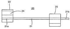
이어서 제2 실시예에 관해서 도 3a, 도 3b 및 도 4를 참조하여 설명한다. 여기에 나타내는 가속도 센서(20)에서는 압전 소자(21)의 일단(21a)에 추 케이스(22)가 장착되고, 타단(21b)측에 지지부재(23)가 장착된다. 추 케이스(22)에는 추(24)와 압전 소자(21)의 일단(21a)측이 압입된다. 지지부재(23)에는 압전 소자(21)의 타단(21b)측이 압입되어 있다. 지지부재(23)는 고정부(25)에 압입되고, 이 고정부(25)는 보수계 본체의 적당한 곳에 비스(vis)(26)에 의해서 고정된다.Next, the second embodiment will be described with reference to FIGS. 3A, 3B and 4. In the
이러한 가속도 센서(20)는, 예컨대 도 5에 도시하는 것과 같이 보수계에 내장된다. 여기서는 압전 소자(21)가 수평 방향을 향하도록, 가속도 센서(20)가 보수계의 본체 케이스(30) 내에 고정구(25)에 의해 고정되며, 압전 소자(21)가 기판(31)에 리드선(32)에 의해서 접속된다. 또, 기판(31)에는 표시기(33)와 스위치(34)가 설치되어 있다.Such an
가속도 센서를 복수개 갖춘 보수계의 경우에는, 가속도 센서를 중심에서부터 등각도 간격을 둔 복수의 가상축 방향으로 각각 배치하는데, 특히 2개의 가속도 센서를 사용하는 경우는 서로 수직인 2개의 가상축 방향(수평 방향과 수직방향)으로 각각 배치한다. 그 경우, 2개의 가속도 센서를 도 6에 도시하는 것과 같은 구성으로 하는 것이 바람직하다.In the case of a pedometer equipped with a plurality of acceleration sensors, the acceleration sensors are arranged in a plurality of virtual axis directions with an equiangular interval from the center.In particular, when two acceleration sensors are used, two virtual axis directions (horizontal to each other perpendicular to each other) are horizontal. Direction and vertical direction). In that case, it is preferable to make two acceleration sensors into the structure as shown in FIG.
도 6을 참조하여 2개의 가속도 센서(40a, 40b)가 수평 방향과 수직 방향으로 배치되어 일체화되어 있다. 즉, 가속도 센서(40a, 40b)는 각각 일단측이 고정단으로서 일체화된 지점 P에서 수평 방향과 수직 방향으로 연장되는 예컨대 쐐기(shim)재와 같은 탄성판(41a, 41b)과, 각 탄성판(41a, 41b)에 첨부된 압전 소자(42a, 41b)와, 각 탄성판(41a, 41b)의 타단측에 설치된 추(43a, 43b)를 갖는다. 탄성판(41a, 41b)은, 예컨대 1장의 띠형상 탄성판을 직각으로 접어 구부림으로써 형성할 수 있으며, 절곡점이 지점 P가 된다.6, two
이러한 구성으로 함으로써, 복수의 가상축 방향으로 각각 개별적으로 가속도 센서를 배치하는 것에 비해, 복수개분의 가속도 센서를 낮은 가격으로 제공할 수 있다. 또, 도 6에서는 2개의 가속도 센서의 예를 나타냈지만, 3개 이상의 가속도 센서를 사용하는 경우, 즉 3축 이상의 방향의 가속도를 검출하는 경우는 그에 따른수의 탄성판을 지점 P에서부터 방사상으로 설치하면 된다.With such a configuration, it is possible to provide a plurality of acceleration sensors at a low price as compared with arranging the acceleration sensors individually in the plurality of virtual axis directions. In addition, although the example of two acceleration sensors was shown in FIG. 6, when using three or more acceleration sensors, ie, when detecting acceleration in the direction of three or more axes, the number of elastic plates according to this is installed radially from the point P. Just do it.
(3) 제3 실시예(3) Third embodiment
이어서 제3 실시예에 따른 보수계에 사용하는 가속도 센서의 구성예와 보수계 본체의 장착예를 도 7 및 도 8을 참조하여 설명한다. 여기서는 보수계 본체(50)의 한쌍의 대향벽에 베어링(51,52)이 각각 고정되며, 이 베어링(51,52)에 축(+ 극)(53)과 축(-극)(54)이 지지되고, 축(53,54)의 축 방향에 수직한 방향으로 가속도 센서(60)가 돌출하여 설치되어 있다. 단, 가속도 센서(60)와 -극의 축(54)은 전기적으로 절연되어 있다. 가속도 센서(60)는 변형 게이지(61)를 가지며, 그 선단에 추(62)가 설치되어 있다. 가속도 센서(60)의 지점부가 되는 축(53,54) 중, -극의 축(54)에는 추(62)보다도 무거운 추(55)가 설치되어 있다.Next, a configuration example of an acceleration sensor and a mounting example of a pedometer main body used in the pedometer according to the third embodiment will be described with reference to FIGS. 7 and 8. Here, the
이에 의해, 가속도 센서(60)는 축(53,54)을 지점으로 하여 360도 자유롭게 회전할 수 있다. 본체(50)가 어떤 방향을 향하더라도, 추(55)가 연직 방향(하향)으로 위치하기 때문에, 가속도 센서(60)는 항상 지면과 평행한 수평 캔틸레버식 지지 상태를 유지한다. 이 경우, 가속도 센서(60)가 360도 자유롭게 회전하기 때문에, 가속도 센서는 1개로 충분하며, 아울러 제1 및 제2 실시예의 보수계로 사용하는 각도 검출 센서는 불필요하다.As a result, the
이어서 제1 실시예의 보수계에 있어서의 각도 검출 센서의 작동 상태를 도 9을 참조하여 설명한다. 도 9에 도시된 각도 검출 센서는 중심에서부터 등거리로 배치된 4개의 도전성의 핀 ①∼④과, 이들 핀 ①∼④이 내측에 위치하여, 핀 ①∼④의 주위에 핀에 접촉하도록 회전이 자유롭게 배치된 도전성 링(70)을 갖는다. 4개의 핀 ①∼④ 중, 핀 ①,④과 핀 ②,③은 각각 전기적으로 접속되어 있다. 또, 핀 ①∼④는 보수계 본체에 내장된 기판에 돌출되어 고정되어 있다.Next, the operation state of the angle detection sensor in the pedometer of the first embodiment will be described with reference to FIG. 9. In the angle detection sensor shown in Fig. 9, four
여기서, 보수계 본체가 반시계 방향으로 회전하면, 도 9에 도시하는 것과 같이 4개의 핀 ①∼④은 동시에 회전한다.Here, when the pedometer main body rotates counterclockwise, as shown in Fig. 9, the four
도 9의 A, B 상태에서는 링(70)이 핀 ①,②에 접촉하여, 4개의 핀 ①∼④ 모두가 전기적으로 접속하고 있기 때문에, 본체는 수평 방향 부근을 향하고 있다고 판정할 수 있다. 한편, 도 9의 C, D, E 상태에서는 링(70)이 핀 ②하고만 접촉한다. 또, F, G 상태에서는 링(70)은 핀 ②,③과 접촉하여, 모두 핀①,④, 핀 ②,③은 전기적으로 접속하고 있지 않기 때문에, 본체는 수직 방향 부근을 향하고 있다고 판정할 수 있다. 이에 의해, 본체가 수평 방향 부근 또는 수직 방향 부근 중 어느 쪽으로 기울고 있느냐를 검출할 수 있다. 물론, 본체가 시계 방향으로 회전하는 경우도 마찬가지이다.In the states A and B of FIG. 9, since the
도 2에 있어서, 도 9와 같이 구성한 각도 검출 센서(5)에 의해, 보수계 본체의 경사 상태를 가리키는 신호가 MPU(16)에 입력된다. 예컨대, 보수계 본체의 경사를 수평 방향이라고 MPU(16)에서 판정하였으면, 수평 방향의 가속도 센서(3)에 관련한 아날로그 증폭 회로(11)와 비교기(12)의 전원에 MPU(16)의 출력 포트에서부터 전류가 공급된다. 또, 이 때 수직 방향의 가속도 센서(4)에 관련된 아날로그 증폭 회로(14)와 비교기(15)의 전원에는 전류가 공급되지 않는다. 반대로, 보수계 본체의 경사를 수직 방향이라고 MPU(16)에서 판정하였으면, MPU(16)의 출력 포트에서부터 아날로그 증폭 회로(14)와 비교기(15)의 전원에 전류가 공급되지만, 아날로그증폭 회로(11)와 비교기(12)의 전원에는 전류가 공급되지 않는다. 이와 같이 하여, 각도 검출 센서(5)의 출력에 따라서 아날로그 회로(10,13)의 전원을 제어한다.In FIG. 2, the signal indicating the inclination state of the pedometer main body is input to the
이 아날로그 회로(10,13)의 전원 제어에 관련하여, 사용하는 가속도 센서를 변경한 경우, 즉 아날로그 회로에의 전류가 끊긴 상태에서 전류가 들어간 상태가 된 경우, 신속한 응답성을 확보하기 위해서는 전원 공급시의 개시 시간을 될 수 있는 한 짧게 하는 것이 바람직하다. 예컨대 도 10에 도시하는 것과 같은 회로에서, 신호가 입력되지 않은 경우, VOUT에는 기준 전압 V1 이 출력된다. 다이오드 D가 없는 상태에서 연산 증폭기에 전원이 공급되면, VOUT이 V1이 될 때까지 수초를 필요로한다. 이것은 저주파 영역에 있어서, 증폭율을 상승시키기 위해서는 콘덴서 C1의 정수 및 저항 R2의 정수가 커야 하므로, 콘덴서 C1의 충전 시간이 길어지기 때문이다. 이 결과, 전원 공급시의 개시 시간이 길어진다.In the case of changing the acceleration sensor to be used in connection with the power supply control of the
그래서, 다이오드 D를 도 10에 도시하는 것과 같이 배선함으로써, 콘덴서 C1의 충전이 저항 R2를 통하지 않고서, 다이오드 D를 통해 이루어진다. 그 결과, 충전 시간이 줄어들어, 전원 공급시의 개시 시간이 1/2 이하로 된다. 다이오드 D 대신에 도 11에 도시하는 것과 같이 MPU에 의해 제어되는 아날로그 스위치 SW1를 배치하여도 좋다. 이 경우, 증폭 회로에 전원이 투입되고 나서 아날로그 스위치 SW1를 일정 시간 온(ON) 상태로 하면, 상기와 같은 작용에 의해, 충전 시간이 줄어들어, 전원 공급시의 개시 시간이 단축된다.Thus, by wiring the diode D as shown in FIG. 10, the charging of the capacitor C1 is made through the diode D without passing through the resistor R2. As a result, the charging time is reduced, and the start time at the time of power supply becomes 1/2 or less. Instead of the diode D, an analog switch SW1 controlled by the MPU may be disposed as shown in FIG. In this case, if the analog switch SW1 is turned ON for a predetermined time after the power is supplied to the amplifier circuit, the charging time is shortened by the above-described action, and the start time at the time of power supply is shortened.
이어서 제1 실시예에 따른 보수계의 각도 검출 처리 동작을 도 12 내지 도14를 참조하여 설명한다. 물론, 걸음수 측정에 앞서서, 보수계 본체(1)는 벨트에 장착하거나, 주머니 속이나 가방 속등에 넣어 놓는다. 우선 단계(이하, ST라 한다) 1에서, 처리 타이밍인가 아닌가를 질문하여, '아니오'라면 처리를 종료한다. '예'라면 각도 검출 센서(5)의 회로 전원을 투입한다(ST2). 여기서 처리 타이밍은 예컨대 250ms(샘플링 4Hz)마다 각도 검출 처리를 행하는 것이다. 각도 검출 센서(5)의 출력 신호는 MPU(16)에 입력되어, MPU(16)는 그 신호를 데이터 D로서 판독하고(ST3), 그 후에 각도 검출 센서(5)의 회로 전원을 차단한다(ST4). 처리 타이밍시에 있어서, 각도 검출 센서(5)에 전원을 투입하여, 데이터 D를 추출한 후, 각도 검출 센서(5)의 전원을 차단하고 있기 때문에, 저소비 전류화 및 전원의 장기 수명화를 도모할 수 있다.Next, the angle detection processing operation of the pedometer according to the first embodiment will be described with reference to FIGS. 12 to 14. Of course, prior to the step measurement, the
다음의 ST5에서는 제1 가속도 센서(3)를 사용하고 있는가 아닌가를 판정하고, 판독한 데이터 D가 로우(Low)인지 아닌지 판정한다(ST6). 이것이 '예'이면 계수기 i≥4인지 아닌지를 판정하여(ST7), 이것도 '예'라면 사용 가속도 센서를 제2 가속도 센서(4)로 변경하여(STl0), 계수 i를 0으로 초기화하여(ST11), 처리를 종료한다. 즉, 각도 검출 센서(5)에 의해 일정 주기마다 검출된 본체의 경사 각도의 출력 신호가 변화하고, 이 변화된 출력 신호는 미리 설정한 회수의 주기(여기서는 4회) 동안 연속적이기 때문에, 사용하는 가속도 센서를 변경한다. 또, ST6에서 '아니오'인 경우는 계수기 i를 0으로 하고(ST8), ST7에서 '아니오'인 경우는 계수기 i=i+1로 하여(ST9), 각각 처리를 종료한다.In the next ST5, it is determined whether or not the
한편, ST5에서 '아니오'인 경우, 데이터 D가 하이(Hi)인지 아닌지를 판정한다(ST12). 이것이 '예'이면 계수기 i≥4인지 아닌지를 판정하여(ST13), 이것도 '예'이면 상기한 이유에 근거하여, 사용 가속도 센서를 제1 가속도 센서(3)로 변경한다(ST16). 계수기 i=0으로 하여(ST11), 처리를 종료한다. ST12에서 '아니오'인 경우는 계수기 i=0로 하고(ST14), ST13에서 '아니오'인 경우는 계수기 i=i+1로 하여(ST15), 각각의 처리를 종료한다.On the other hand, in the case of NO in ST5, it is determined whether or not the data D is Hi (ST12). If this is YES, it is determined whether or not the counter i≥4 (ST13). If this is also YES, the used acceleration sensor is changed to the
상기 흐름도에서 알 수 있는 바와 같이, MPU(16)에서는 각도 검출 센서(5)로부터의 데이터 D에 근거하여 수평 방향 또는 수직 방향의 어느쪽의 가속도 센서로부터의 출력 신호를 선택하는지를 판정하여, 선택된 가속도 센서로부터의 출력 신호에 의해 걸음수를 계수한다. 또, 각도 검출 센서(5)에 의한 각도 변화를 소정회수(4회) 연속하여 검출한 경우에, 사용하는 가속도 센서를 변경하고 있기 때문에, 보행 등의 신체의 움직임에 의한 각도 검출 센서의 신호(노이즈)를 소거하여, 각도 검출 센서(4)의 오류 인식을 막을 수 있다(도 14 참조).As can be seen from the flowchart, the
이어서 본원 발명의 보수계에 이용되는 각도 검출 센서의 다른 실시예에 관해서 설명한다.Next, another Example of the angle detection sensor used for the pedometer of this invention is described.
(4) 제4 실시예(4) Fourth Embodiment
도 15a 내지 도 15d 및 도 16a, 도 16b를 참조하면, 이 실시예에 따른 각도 검출 센서(51)는 케이스(52), 이동체로서의 볼(ball)(53), 광학 센서를 구성하는 적외 발광 다이오드(54) 및 적외 광트랜지스터(55), 이동체의 이동 범위로서의 중공부(hollow portion)(56)로 이루어진다.15A to 15D, and 16A and 16B, the
케이스(52)의 거의 중앙에 설정된 대략 직방체의 중공부(56) 내에, 원형의볼(53)이 이동이 자유롭도록 수납되어 있다. 볼(53)은 벽으로서의 내측면(56a,56b,56c,56d)과, 상면(56e) 및 하면(56f)dmfh 둘러싸인 중공부(56) 내를 이동한다. 상면(56e)과 하면(56f)과의 간격은 볼(53)의 지름보다도 약간 크게 설정되어 있기 때문에, 주로 내측면(56a,56b,56c,56d) 사이를 이동한다.In the hollow portion 56 of the substantially rectangular parallelepiped set near the center of the
케이스(52)는 합성 수지로 성형하고, 볼(53)은 고무 등의 탄성재로 이루어진다. 이러한 재질로 형성함으로써, 예컨대 자기(磁氣)가 존재하는 곳에 사용하여도 검출 정밀도에 영향을 주는 일은 없지만, 재질이 이들에 한정되는 것은 아니다. 케이스(52)의 내측면(56a,56b,56c,56d)은 평탄면에 한정되지 않고, 볼(53)의 곡면에 대응한 홈을 길이 방향으로 형성하여도 좋다. 이동체는 볼(53)과 같은 구(球)체에 한정되는 것은 아니며, 원통이나 원주 등이라도 좋고, 단면을 원에 한하지 않고 타원으로 하여도 좋다.The
대략 직방체를 이루는 중공부(56)의 대향하는 2변상에는 개구부(57,58)가 설치되어 있다. 이 개구부(57,58)의 외측에 각각 설치된 오목부(59,60)에는 적외 발광 다이오드(54)와 적외 광트랜지스터(55)가 각각 대향하여 수납되어 있다. 적외 발광 다이오드(54)와 적외 광트랜지스트(55)로부터는 각각 리드(54a, 54b, 55a, 55b)가 케이스(52) 밖으로 인출되어 있다. 볼(53), 적외 발광 다이오드(54) 및 적외 광트랜지스터(55)는 케이스(52) 내에 밀봉되어 설치되어 있기 때문에, 외부의 난광(disturbance light)이나 먼지의 침입에 의해 검출 정밀도가 저하되는 일은 없다.
도면 중 ℓ은 발광 다이오드(54)와 광트랜지스터(55)를 연결하는 광축이며,m1,m2는 광축 ℓ과 직교하는 평면이다. 본 실시예에서는 평면 m1에 대하여 내측면(56a,56b)이 이루는 각도 α, α'와, 평면 m2에 대하여 내측면(56c,56d)이 이루는 각도 β, β'는 모두 45도로 설정하고 있다.1 is an optical axis connecting the
도 17은 각도 검출 센서(51)의 회로 구성을 도시한 도면이다. 발광 다이오드(54)에 직렬로 과대 전류 유입 방지용의 저항 R0이 접속되고, 광트랜지스터(55)의 에미터측에 저항 R1이 직렬로 접속되어 있다. 회로(62)에 순방향 전류를 흘림으로써 적외 발광 다이오드(54)가 발광한다. 이 광이 수광 소자의 수광면에 도달하면, 적외 광트랜지스터(55)의 콜렉터·에미터 사이가 도통하여 회로(63)에 전류 Ic가 흐른다. 이 전류 Ic에 의해, 저항 R1의 양단에 나타나는 전압 Ic R1을 에미터측에 설치한 출력 단자(64)를 통해 취득하여 관측한다.17 is a diagram showing the circuit configuration of the
이하, 제4 실시예에 따른 각도 검출 센서(51)의 검출 원리를 설명한다.Hereinafter, the detection principle of the
각도 검출 센서(51)는 도 15b에 나타내는 B-B 단면에 평행한 면이 검출 기준면이 되며, 이 면 내에 있어서의 수평 방향으로부터의 경사 각도를 검출한다. 따라서, 측정 대상의 검출 기준면과 각도 검출 센서(51)의 검출 기준면이 평행이 되도록 케이스(52)를 측정 대상에 장착하는 동시에, 검출 기준면이 거의 연직이 되도록 측정 대상 및 센서를 유지할 필요가 있다.As for the
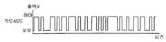
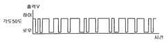
도 18은 검출 기준면 내에서 각도 검출 센서(51)를 소정의 각도만큼 경사지게 한 상태를 B-B 단면도로 나타내고 있다. 경사각이 0도에서 30도 정도인 경우에는 볼(53)은 개구부(58)에 위치하여, 발광 다이오드(54)로부터 광트랜지스터(55)에 이르는 광축상에 있어, 상술한 전류 Ic는 흐르지 않아, 광트랜지스터(55)로부터의 출력은 없다. 경사각이 60도 정도에서 90도인 경우에는 볼(53)은 제1 정류부(stopping position)(61)에 위치하여, 볼(53)이 광축상에 없기 때문에 상술한 전류 Ic가 흘러 광트랜지스터(55)로부터의 출력이 존재한다. 한편, 경사각이 45도 근방인 경우에는 볼(53)은 볼의 형상이나 케이스의 내측면과의 접촉 조건 등에 의해, 개구부(58)에서부터 굴러나와 내측면(56d)상을 제1 정류부(61)까지 굴러간다. 내측면(56a)에 충돌하여 되튀겨져 다시 내측면(56d)상을 개구부(58)까지 되돌아가고, 이번에는 내측면(56c)에 충돌하여 되튀겨진다고 하는 식으로 내측면(56a, 56c) 사이에서 진동한다. 따라서, 경사각 45도의 근방에서는 광축상을 몇번이나 가로 질러, 광트랜지스터(55)로부터의 출력이 단속적으로 나타나게 된다. 이 경사각 45도 근방에서의 각도의 추정 방법에 관해서 이하에 설명한다.18 is a B-B cross-sectional view showing a state in which the
도 19a 내지 도 19d는 광트랜지스터(55)의 출력이 발생하고 있는 경우에는 하이 레벨이 되고, 출력이 발생하지 않는 경우에는 로우 레벨이 되도록 비교기에 의해서 변환된 펄스 신호의 변화를 나타낸다. 도 19a 내지 도 19d에 도시하는 것과 같이, 소정 시간 내에서의 하이 레벨 신호의 출현 빈도는 경사 각도에 따라서 다르다. 즉, 소정의 경사 각도에 대응하는 하이 레벨 신호의 소정 시간 내에서의 출현 빈도를 기억시켜 놓아, 광트랜지스터(55)의 출력과 비교함으로써 경사 각도의 추정이 가능하게 된다.19A to 19D show the change of the pulse signal converted by the comparator so as to be at a high level when the output of the
본 실시예에 따른 각도 검출 센서에 의한 각도 추정 방법을 가리키는 흐름도를 도 20에 나타낸다. 우선 ST21에 있어서 i=0, k=0로 설정한다. 이어서 ST22에 있어서 각도 검출 센서(55)의 출력이 하이 레벨인가 아닌가를 판단하여, 하이 레벨인 경우에는 ST24로 진행하여 k=k+1로 설정한다. 하이 레벨에 없는 경우에는 ST23로 진행하여, i=i+1로 설정한 후 ST24로 진행한다. ST24에서 ST25로 진행하여, k=n인가 아닌가를 판단하여, k=n이 아닌 경우는 ST26에서 시간 T0대기하여 ST22에 복귀한다. k=n인 경우에는 ST27로 진행하여, i<Nth(Nth는 N번째)인가 아닌가를 판단한다. ST27에 있어서, i<;Nth인 경우에는 각도가 45도 미만이라고 판정하고, i<;Nth가 아닌 경우에는 각도가 45도 이상이라고 판정하여, A로 복귀한다.20 is a flowchart showing an angle estimation method by the angle detection sensor according to the present embodiment. First, i = 0 and k = 0 are set in ST21. Next, in ST22, it is judged whether or not the output of the
여기서, i는 일정 시간 내의 펄스, Nth는 상술한 것과 같이 45도에 대응하여 설정된 값이다. 또, 본 실시예에서는 T0는 250 msec이며, 4 sec 동안 샘플링을 행하고 있다. 이 흐름도에서는 일정 시간 내의 펄스수를 계측하고 있지만, 일정 시간 내에서의 하이 레벨 또는 로우 레벨의 출현 시간을 계측하여도 마찬가지로 각도의 검출이 가능하다.I is a pulse within a predetermined time, and Nth is a value set corresponding to 45 degrees as described above. In the present embodiment, T0 is 250 msec and sampling is performed for 4 sec. In this flowchart, the number of pulses is measured within a certain time, but the angle can be detected similarly by measuring the appearance time of a high level or a low level within a certain time.
도 21은 상술의 처리를 행하는 각도 검출 센서를 포함시킨 각도 검출 장치의 개략적인 구성을 보이는 블럭도이다. 각도 검출 센서(51)가 각도에 대응하는 전기 신호를 발생한다. 그 신호를 A/D 변환기(65)가 1비트 이상의 디지탈 신호로 변환하여, 이 디지탈 신호 MPU가 계산 처리를 행하여, 각도를 추정, 결정한다.Fig. 21 is a block diagram showing a schematic configuration of an angle detecting device including an angle detecting sensor that performs the above-described processing. The
이와 같이, 본 실시예에 따른 각도 검출 센서를 장착한 측정 대상이 정지하거나 혹은 볼(53)이 주로 내측면을 회전하는 정도로 느슨하게 이동하는 경우에 있어서는 각도 검출 센서 본체의 경사 각도가 45도 미만인가 이상인가를 정확하게 검출할 수 있다. 또, 측정 대상이 일정 방향으로 회전하는 경우에는 볼(53)은 중공부(56) 내에 있어서 상술한 운동을 반복하기 때문에, 회전수를 검출할 수가 있다.As described above, in the case where the measurement target with the angle detection sensor according to the present embodiment is stopped or the
또한, 본 실시예에서는 내측면(56a,56b)이 평면 m1에 대해 이루는 각도 α, α', 내측면(56c,56d)이 평면 m2에 대해 이루는 각도 β, β'는 모두 45도로 설정하고 있지만, 이들의 각도의 설정을 변경하면, 도 20에 나타내는 순서로 45도 이외의 각도에 관해서도 원하는 각도 이상인가 미만인가를 결정할 수 있다.In this embodiment, the angles α, α 'formed by the
여기서, 본 실시예에서는 α=α', β=β'이지만, α≠α', β≠β'로 하여, 평면 m1에 대하여 내측면(56a)이 이루는 각도와 내측면(56b)이 이루는 각도가 다르게 하고, 같은 식으로 평면 m2에 대하여 내측면(56c)이 이루는 각도와 내측면(56d)이 이루는 각도가 다르게 하더라도 좋다. 단, 일정 방향으로 각도 검출 센서를 180도 회전시킨 경우에도, 마찬가지로 각도를 검출하기 위해서는 서로 대향하는 내측면끼리는 평행하게 형성할 필요가 있어, α=β, α'=β'가 아니면 안된다. 따라서, 중공부의 형상은 본 실시예와 같은 직방체에 한정되지 않고, 검출 기준면에 평행한 단면이 마름모형, 직사각형 등의 평행 사변형이 되도록 하여도 좋다.Here, in the present embodiment, α = α 'and β = β', but α? Α 'and β ≠ β', and the angle formed by the
(5) 제5 실시예(5) Fifth Embodiment
제4 실시에 있어서는 정지 상태 또는 느슨하게 회전시킨 경우 등의 각도 검출에 관해서 설명하였다. 제5 실시예에서는 사람의 보행과 같은 연동을 동반하는경우의 각도 검출에 관해서 설명한다. 각도 검출 센서 및 각도 검출 장치 자체의 구성은 제4 실시예와 같기 때문에, 같은 부호를 붙여 상세한 설명은 생략한다. 상술한 것과 같은 연동을 동반하는 경우에는 각도 검출 센서(51) 본체의 경사 각도의 여하에 관계 없이, 볼(53)은 내측면(56a,56b,56c,56d)에 반복하여 충돌하여 중공부(56)내를 항상 이동하고 있다. 이 이동에 의해, 광트랜지스터(55)의 출력이 각도 검출 센서(51) 본체의 경사 각도의 여하에 관계 없이 단속적으로 나타나게 된다.In the fourth embodiment, the angle detection such as the stationary state or the case of loose rotation was described. In the fifth embodiment, the angle detection in the case of accompanied by a linkage such as human walking will be described. Since the configuration of the angle detection sensor and the angle detection device itself is the same as that of the fourth embodiment, the same reference numerals are assigned to the detailed description thereof. In the case of accompanying the linkage as described above, irrespective of the inclination angle of the main body of the
볼(53)의 운동 상태를 고찰하면, 운동을 야기하는 각도 검출 센서(51) 본체의 운동은 일정하지 않다고 해도, 볼(53)에 작용하는 중력과 운동의 속박 조건인 내측면(56a, 56b, 56c, 56d)이 형성하는 상대적인 각도는 각도 검출 센서(51) 본체의 경사 각도에 의해서 정해지는 것이다. 즉, 볼(53)의 운동 상태는 각도 검출 센서(51) 본체의 경사 각도에 지배된다.Considering the motion state of the
따라서, 제4 실시예에서의 45도 근방에서의 각도 검출 원리와 같은 원리에 근거하여, 광트랜지스터(55)의 출력의 하이 레벨 신호의 일정 시간 내의 출현 빈도에 의해서, 각도를 추정, 결정할 수가 있다. 도 20의 흐름도에 있어서의 Nth를 각도마다 설정해 놓으면, 같은 처리 순서에 의해 45도 근방뿐만 아니라 모든 각도에 대해서 검출이 가능하게 된다.Therefore, on the basis of the same principle as the angle detection principle in the vicinity of 45 degrees in the fourth embodiment, the angle can be estimated and determined by the frequency of appearance of the high level signal at the output of the
(6) 다른 실시예(6) another embodiment
이하, 본 발명의 다른 실시예에 대해서 설명한다. 제4 및 제5 실시예와 같은 구성을 갖는 부분에 대해서는 같은 부호를 붙여 상세한 설명은 생략하고, 상이한부분에 대해서만 설명한다.Hereinafter, another Example of this invention is described. Parts having the same configuration as those in the fourth and fifth embodiments are denoted by the same reference numerals, and detailed description thereof will be omitted, and only different portions will be described.
제4 및 제5 실시예에서는 유무 검출 수단으로서 발광 다이오드(54)와 광트랜지스터(55)로 이루어지는 광학 센서를 사용하였다. 그러나, 소정 영역 내에 있어서의 이동체의 유무가 검출될 수 있으면 좋고, 전자파, 음파 및 초음파 등에 의해서 유무를 검출하는 것이라도 좋다. 적외 발광 다이오드(54) 대신에 적외 발광 레이저를 사용하여도 좋고, 적외 광트랜지스터(55)의 대신에 적외 광다이오드를 사용하여도 좋다.In the fourth and fifth embodiments, an optical sensor composed of a
또, 제4 및 제5 실시예에서는 볼(53)의 이동 범위는 대략 직방체의 공간이며, 상면(56e)과 하면(56f) 사이는 거의 연동하지 않고, 말하자면 2차원적으로 운동하고 있다. 그러나, 이에 한하지 않고, 이 공간을 광학 센서의 광축에 축대칭으로 형성하여, 3차원적으로 운동하도록 하여도 좋다. 이와 같이 하면, 광축을 포함하는 모든 면을 검출 기준면으로 할 수 있다. 다만, 공간이 광축에 축대칭인 것에 한정되지 않는 것은 당연하다.In addition, in the 4th and 5th Example, the movement range of the
더욱이, 제4 및 제5의 실시예에서는 이동체인 볼(53)의 이동 범위는 케이스(52)의 내측면(56a, 56b, 56c, 56d) 및 상면(56e), 하면(56f)에 규제된 공간이지만, 이동체의 이동 범위를 규제하는 것은 이에 한하지 않고, 용수철 등의 탄성체로 지지되어 있더라도 좋다. 이 실시예에서는 각도 검출 센서 본체의 경사에 따라 이동 범위 내에서의 이동체의 운동 상태가 변화하는 것에 착안하였다. 그리고, 그 변화하는 운동 상태를 이동 범위 내의 소정 영역에 있어서의 이동체의 일정 시간 내의 출현 시간 또는 빈도로서 취득하여 그에 의해 각도를 검출하도록 하였다.그 결과, 각도 검출 센서 본체의 경사에 따라 이동 범위 내에서의 이동체의 운동 상태가 변화하도록 이동체의 이동 범위가 규제되어 있으면 각도의 검출이 가능하다.Furthermore, in the fourth and fifth embodiments, the moving range of the moving
(7) 활동 모니터 및 열량계(7) activity monitor and calorimeter
이어서 상기 보수계의 원리를 응용한 활동 모니터나 열량계에 관해서 설명한다. 활동 모니터나 열량계의 외관 및 회로 블럭도는 상기 실시예에 나타낸 보수계와 동일하지만, 그 동작 소프트와 표시 데이터가 다르다.Next, the activity monitor and calorimeter which apply the principle of the said pedometer are demonstrated. The appearance and circuit block diagram of the activity monitor and calorimeter are the same as those of the pedometer shown in the above embodiment, but the operation software and the display data differ.
도 22는 활동 모니터 및 열량계의 주요부를 나타내는 블럭도이고, 기본적으로 도 2와 같다. 도 22를 참조하면, 활동 모니터 및 열량계는 인체에 장착되어 신체의 움직임를 검출하는 가속도 센서(71)와, 이 가속도 센서(71)로 검출된 신호를 증폭하는 증폭 회로(72)와, 증폭된 신호를 디지탈 신호로 변환하는 A/D 변환 회로(73)와 이하에 설명하는 소정의 기능을 갖는 MPU(74)와 표시기(75)와 스위치(76)와 각 회로에 전원을 공급하는 전원 회로(77)를 포함한다. MPU(74)는 입력된 디지탈 신호에 근거하여 운동량을 산출하는 기능, 소정 기간(예컨대 1일)의 추정 소비 칼로리를 이용하여 남은 목표 칼로리를 산출하는 남은 목표 칼로리 산출 기능, 인체가 소정 기간(1일)에 소비하는 데에 바람직한 목표 운동량을 산출하는 목표 운동량 산출 기능, 실측된 운동량에서 생활 활동 지수를 산출하는 생활 활동 지수 산출 기능을 갖는다. 표시부(75)에는 성별, 연령, 운동량, 생활 활동 강도 등이 표시된다. 스위치(76)는 전원 온/오프 스위치나, 표시 종류를 선택하는 선택 스위치나, 성별·연령 등을 입력하는 스위치 등을 포함한다.FIG. 22 is a block diagram showing main parts of an activity monitor and a calorimeter, and is basically the same as FIG. 2. Referring to FIG. 22, an activity monitor and a calorimeter are mounted on a human body to detect an
이 운동량 측정 장치에서는 각종 연산 기능에 의해 운동이나 생활 활동 강도 등을 산출한다. 이 산출에는 기초 대사량이 필요하여, 기초 대사량을 구하는 방법은 여러가지 있지만, 일례로서 다음 수학식 1을 이용하여 구하는 방법이 있다. 즉, 기초 대사량 B는In this exercise amount measuring device, exercise, daily activity intensity and the like are calculated by various calculation functions. The basal metabolic amount is required for this calculation, and there are various methods for obtaining the basal metabolic amount. That is, the basal metabolic rate B

로 구할 수 있다. 단, 이 수학식 1은 연령이 6세 이상인 경우에 한정되며, 또 Bs는 성별·연령에 따라 다른 값을 보여, 예컨대 「일본인의 영양 소요량(제5차 개정) 」으로 구할 수 있다.Can be obtained as However, this equation (1) is limited to the case where the age is 6 years or older, and Bs shows a different value depending on the sex and age, and can be obtained as, for example, the nutritional requirement of the Japanese (the fifth revision).
한편, 생활 활동 지수의 산출은 다음과 같이 한다. 1일 총 에너지 대사량 A는 연동 등에 의해 소비되는 에너지 B·χ, 기초 대사량 B, 및 특이 동적 작용에 의한 대사량(0.1·A : 섭취한 음식물을 분해·흡수하는 데에 필요한 에너지)으로 다음 수학식 2에 의해 나타내여진다(단, χ은 생활 활동 지수).On the other hand, calculation of life activity index is as follows. Total daily energy metabolism A is energy B · χ, basic metabolic amount B, and metabolic amount (0.1 · A: energy required to decompose and absorb foods consumed) by specific dynamics. It is represented by 2 (where χ is the life activity index).
이 식을 변형하여,By transforming this expression,
이 되므로, 성별·연령·신장·체중에서부터 계산에 의해 구한 기초 대사량 B와, 이 기초 대사량 B와 가속도 센서의 신호 파형에서 얻어진 운동의 강도를 이용하여 MPU에 의해 계산되는 총 에너지 대사량 A를 상기 수학식 3에 대입하면, 생활 활동 지수 X를 얻을 수 있다.Therefore, the basic metabolic amount B calculated by the calculation from sex, age, height, and weight, and the total energy metabolic amount A calculated by the MPU using the basic metabolic amount B and the intensity of the exercise obtained from the signal waveform of the acceleration sensor are calculated. Substituting into
산출된 생활 활동 지수 χ는 생활 활동 강도에 의해 예컨대 4단계로 랭크를 구분함으로써, 운동의 레벨이 어느 정도인가를 알 수 있다.The calculated life activity index χ is divided into ranks, for example, in four stages according to the strength of life activity, and it can be known how much the level of exercise is.
다른 한편, 목표 운동량은 상기 생활 활동 지수 χ를 목표로 하여 산출한다. 이 경우, 생활 활동 지수 χ는 타당한 값으로서 0.5로 설정하는 동시에, 상기 수학식 2를 이용한다. 즉, 목표 운동량 A는 A = B·χ + B + (1/10)A 이므로, 이에 의해 A = (10/9)·(1+χ)·B 가 되고, χ = 0.5로 하면,On the other hand, the target exercise amount is calculated by targeting the living activity index χ. In this case, the living activity index χ is set to 0.5 as a valid value and the above equation (2) is used. That is, since the target momentum A is A = B · χ + B + (1/10) A, A = (10/9) · (1 + χ) · B, whereby χ = 0.5,
가 되어, 목표 운동량 A를 산출할 수 있다.The target exercise amount A can be calculated.
이어서 표시기(5)의 표시 화면의 표시 형태에 관해서 설명한다. 도 23은 표시 화면의 예를 나타내는 도면이다. 도 23을 참조하면, 표시 화면은 상부(80)와 하부(81)로 분리되어 있고, 상부(80)에 운동량(총 소비 칼로리, cal)이 숫자로 표시되며, 하부(81)에 과거 1주간과 1주간의 평균 생활 활동 강도가 막대 그래프로 표시된다. 활동 강도는 I(가볍다), II(중간정도), III(약간 무겁다)의 3단계로 분리되고 있으며, II(중간정도)가 목표 레벨로 설정되어 있다. 이 표시 형태에서는 하루의 마지막에 생활의 활동량(총 소비 칼로리) 및 활동 강도가 산출되어, 자동적으로 표시된다. 또, 과거 1주간(7일간)의 각 날의 소비 칼로리와 각 날의 활동 강도, 7일간의 평균의 소비 칼로리와 평균 활동 강도가 표시된다. 1주간의 소비 칼로리와 활동 강도를 기록하기 위해서는 예컨대 자동 메모리 기능을 설치하여 놓으면 좋다. 이 표시 형태에 의하면, 과거 1주간의 운동의 경향을 한눈에 알 수 있다.Next, the display mode of the display screen of the
별도의 표시 형태를 도 24에 나타낸다. 이 표시 형태에 있어서는 성별, 연령, 신장, 체중을 입력하면, 각자에게 적당한 목표 소비 칼로리가 자동적으로 설정 표시된다. 동시에 그 목표 소비 칼로리의 달성율이 막대 그래프와 영상으로 표시된다.Another display form is shown in FIG. In this display mode, when the gender, age, height, and weight are inputted, a target consumption calorie suitable for each is automatically set and displayed. At the same time, the achievement rate of the target calories burned is displayed in bar graphs and images.
또한, 활동 모니터는 도 23의 하반부만을 표시하고, 열량계는 도 23의 상부분만을 표시한다.In addition, the activity monitor displays only the lower half of FIG. 23, and the calorimeter displays only the upper portion of FIG. 23.
이상과 같이, 본 발명에 따른 보수계는 본체를 장착하는 곳을 허리 벨트에 한정할 필요가 없고, 보수계를 옷이나 바지 주머니 안, 가방 안등에 넣어 놓더라도 그 본체의 방향에 따른 센서를 이용하여 진동이 검출되기 때문에, 임의 상태에 있어서 걸음수 측정이 가능하다.As described above, the pedometer according to the present invention does not need to limit the place where the main body is mounted to the waist belt, and even if the pedometer is placed in the clothes, the pants pocket, the inside of the bag, or the like, it vibrates using a sensor according to the direction of the main body Since this is detected, the number of steps can be measured in an arbitrary state.
Claims (21)
Translated fromKoreanApplications Claiming Priority (7)
| Application Number | Priority Date | Filing Date | Title |
|---|---|---|---|
| JP96-130999 | 1995-04-26 | ||
| JP95-233700 | 1995-09-12 | ||
| JP23370095 | 1995-09-12 | ||
| JP32691695 | 1995-12-15 | ||
| JP13099996AJPH09292219A (en) | 1996-04-26 | 1996-04-26 | Angle detecting sensor and angle detecting device |
| PCT/JP1996/002586WO1997010567A1 (en) | 1995-09-12 | 1996-09-11 | Pedometer |
| JP95-326916 | 1996-12-15 |
Publications (2)
| Publication Number | Publication Date |
|---|---|
| KR970707508A KR970707508A (en) | 1997-12-01 |
| KR100287611B1true KR100287611B1 (en) | 2001-04-16 |
Family
ID=27316230
Family Applications (1)
| Application Number | Title | Priority Date | Filing Date |
|---|---|---|---|
| KR1019970703112AExpired - Fee RelatedKR100287611B1 (en) | 1995-09-12 | 1996-09-11 | Pedometer |
Country Status (6)
| Country | Link |
|---|---|
| US (1) | US6254513B1 (en) |
| EP (1) | EP0797169B1 (en) |
| KR (1) | KR100287611B1 (en) |
| CN (1) | CN1159569C (en) |
| DE (1) | DE69628407T2 (en) |
| WO (1) | WO1997010567A1 (en) |
Cited By (1)
| Publication number | Priority date | Publication date | Assignee | Title |
|---|---|---|---|---|
| KR100703451B1 (en)* | 2005-09-16 | 2007-04-03 | 삼성전자주식회사 | Step detection apparatus and method in personal navigation equipment |
Families Citing this family (65)
| Publication number | Priority date | Publication date | Assignee | Title |
|---|---|---|---|---|
| US6266623B1 (en) | 1994-11-21 | 2001-07-24 | Phatrat Technology, Inc. | Sport monitoring apparatus for determining loft time, speed, power absorbed and other factors such as height |
| US8280682B2 (en) | 2000-12-15 | 2012-10-02 | Tvipr, Llc | Device for monitoring movement of shipped goods |
| US7386401B2 (en) | 1994-11-21 | 2008-06-10 | Phatrat Technology, Llc | Helmet that reports impact information, and associated methods |
| DE69628407T2 (en) | 1995-09-12 | 2004-05-06 | Omron Corp. | PEDOMETER |
| GB2379275B (en)* | 2000-05-18 | 2004-01-28 | Yaman Ltd | Exercise signal generator of exercise load meter |
| KR20000054776A (en)* | 2000-06-23 | 2000-09-05 | 이정래 | Calculation mechanism for worship of buddhism |
| JP3543778B2 (en)* | 2000-10-16 | 2004-07-21 | オムロンヘルスケア株式会社 | Pedometer |
| US6826477B2 (en)* | 2001-04-23 | 2004-11-30 | Ecole Polytechnique Federale De Lausanne (Epfl) | Pedestrian navigation method and apparatus operative in a dead reckoning mode |
| EP1256316A1 (en)* | 2001-05-07 | 2002-11-13 | Move2Health B.V. | Portable device comprising an acceleration sensor and method of generating instructions or advice |
| US20030110859A1 (en)* | 2001-11-14 | 2003-06-19 | Ryoichi Fukui | Acceleration sensors and pedometers using same |
| US6965237B2 (en)* | 2002-09-27 | 2005-11-15 | Kuo Shu Shoung | Device for scanning or detecting electromagnetic waves |
| US7107180B2 (en) | 2003-11-14 | 2006-09-12 | Ossur Hf | Method and system for determining an activity level in an individual |
| US20050195094A1 (en)* | 2004-03-05 | 2005-09-08 | White Russell W. | System and method for utilizing a bicycle computer to monitor athletic performance |
| JP2005267152A (en)* | 2004-03-18 | 2005-09-29 | Seiko Instruments Inc | Electronic pedometer |
| JP4785349B2 (en)* | 2004-04-20 | 2011-10-05 | セイコーインスツル株式会社 | Electronic pedometer |
| JP4785348B2 (en)* | 2004-04-20 | 2011-10-05 | セイコーインスツル株式会社 | Electronic pedometer |
| KR100786703B1 (en)* | 2004-07-24 | 2007-12-21 | 삼성전자주식회사 | Device and method for measuring physical exercise using acceleration sensor |
| US7373820B1 (en) | 2004-11-23 | 2008-05-20 | James Terry L | Accelerometer for data collection and communication |
| JP2006313313A (en)* | 2005-04-06 | 2006-11-16 | Sony Corp | Reproducing device, setting switching method, and setting switching device |
| US20060240959A1 (en)* | 2005-04-22 | 2006-10-26 | Hsien-Ting Huang | Dumbbell that can respond to exercise status and play music |
| US7911339B2 (en) | 2005-10-18 | 2011-03-22 | Apple Inc. | Shoe wear-out sensor, body-bar sensing system, unitless activity assessment and associated methods |
| JP4785526B2 (en)* | 2005-12-28 | 2011-10-05 | セイコーインスツル株式会社 | Electronic pedometer |
| JP4586740B2 (en)* | 2006-02-15 | 2010-11-24 | オムロンヘルスケア株式会社 | Body motion detection device |
| JP4785553B2 (en)* | 2006-02-16 | 2011-10-05 | セイコーインスツル株式会社 | Pedometer |
| US7643895B2 (en) | 2006-05-22 | 2010-01-05 | Apple Inc. | Portable media device with workout support |
| US9137309B2 (en) | 2006-05-22 | 2015-09-15 | Apple Inc. | Calibration techniques for activity sensing devices |
| US8073984B2 (en) | 2006-05-22 | 2011-12-06 | Apple Inc. | Communication protocol for use with portable electronic devices |
| US20070271116A1 (en) | 2006-05-22 | 2007-11-22 | Apple Computer, Inc. | Integrated media jukebox and physiologic data handling application |
| US7813715B2 (en) | 2006-08-30 | 2010-10-12 | Apple Inc. | Automated pairing of wireless accessories with host devices |
| US7913297B2 (en) | 2006-08-30 | 2011-03-22 | Apple Inc. | Pairing of wireless devices using a wired medium |
| US7637172B2 (en)* | 2006-09-19 | 2009-12-29 | Mattel, Inc. | Electronic device with speed measurement and output generation |
| NL1032680C2 (en)* | 2006-10-16 | 2008-04-21 | Sensite Solutions B V | Movement sensor comprising movable object, light source and photo detector, sends light pulses into the space containing the object |
| JP4957258B2 (en)* | 2007-01-15 | 2012-06-20 | 富士通株式会社 | Step counting device and step counting method |
| US7698101B2 (en) | 2007-03-07 | 2010-04-13 | Apple Inc. | Smart garment |
| US20080275669A1 (en)* | 2007-04-13 | 2008-11-06 | Tomohiro Ihashi | Pedometer |
| US7634379B2 (en)* | 2007-05-18 | 2009-12-15 | Ultimate Balance, Inc. | Newtonian physical activity monitor |
| US7676332B2 (en) | 2007-12-27 | 2010-03-09 | Kersh Risk Management, Inc. | System and method for processing raw activity energy expenditure data |
| US7905193B2 (en) | 2007-12-28 | 2011-03-15 | Johnson Outdoors Inc. | Trim tabs |
| USD573938S1 (en) | 2007-12-28 | 2008-07-29 | Johnson Outdoors Inc. | Trim tab |
| USD573526S1 (en) | 2007-12-28 | 2008-07-22 | Johnson Outdoors Inc. | Trim tab |
| JP5146343B2 (en)* | 2009-02-06 | 2013-02-20 | オムロンヘルスケア株式会社 | Body motion detection device |
| CA2781615A1 (en) | 2009-11-25 | 2011-06-03 | The Board Of Governors For Higher Education, State Of Rhode Island And P Rovidence Plantations | Systems and methods for providing an activity monitor and analyzer with voice direction for exercise |
| JP5757742B2 (en)* | 2010-03-25 | 2015-07-29 | セイコーインスツル株式会社 | Electronic devices, pedometers, and programs |
| CN102168971B (en)* | 2010-12-24 | 2012-12-05 | 郑州辰维科技股份有限公司 | Two-dimensional inclination measuring system for rendezvous and docking motion simulator |
| US9041600B2 (en) | 2011-02-08 | 2015-05-26 | Cambridge Silicon Radio Limited | Use of GPS to detect repetitive motion |
| CN102243248B (en)* | 2011-04-01 | 2013-08-21 | 可瑞尔科技(扬州)有限公司 | Speed detection device and method capable of automatically differentiating walking and running modes |
| US9339691B2 (en) | 2012-01-05 | 2016-05-17 | Icon Health & Fitness, Inc. | System and method for controlling an exercise device |
| TWI457539B (en)* | 2012-12-19 | 2014-10-21 | Ind Tech Res Inst | Multi-posture step length calibration system and method for indoor positioning |
| WO2014153158A1 (en) | 2013-03-14 | 2014-09-25 | Icon Health & Fitness, Inc. | Strength training apparatus with flywheel and related methods |
| CN103353309B (en)* | 2013-07-30 | 2015-11-25 | 谢虹 | A kind of electronic pedometer |
| WO2015100429A1 (en) | 2013-12-26 | 2015-07-02 | Icon Health & Fitness, Inc. | Magnetic resistance mechanism in a cable machine |
| US10433612B2 (en) | 2014-03-10 | 2019-10-08 | Icon Health & Fitness, Inc. | Pressure sensor to quantify work |
| CN106470739B (en) | 2014-06-09 | 2019-06-21 | 爱康保健健身有限公司 | Cable system incorporated into the treadmill |
| WO2015195965A1 (en) | 2014-06-20 | 2015-12-23 | Icon Health & Fitness, Inc. | Post workout massage device |
| DE102014008939A1 (en) | 2014-06-23 | 2015-12-24 | Martin Daumer | Method and device for determining the movement of a person |
| KR102130801B1 (en) | 2014-07-22 | 2020-08-05 | 엘지전자 주식회사 | Apparatus for detecting wrist step and method thereof |
| US10391361B2 (en) | 2015-02-27 | 2019-08-27 | Icon Health & Fitness, Inc. | Simulating real-world terrain on an exercise device |
| CN104949685B (en)* | 2015-05-22 | 2018-04-27 | 邓伟廷 | The method and its device of accurate meter step can be realized in multi-mode multiple location |
| CN104864885B (en)* | 2015-05-25 | 2018-03-13 | 遵义师范学院 | A kind of running counter |
| US10493349B2 (en) | 2016-03-18 | 2019-12-03 | Icon Health & Fitness, Inc. | Display on exercise device |
| US10272317B2 (en) | 2016-03-18 | 2019-04-30 | Icon Health & Fitness, Inc. | Lighted pace feature in a treadmill |
| US10625137B2 (en) | 2016-03-18 | 2020-04-21 | Icon Health & Fitness, Inc. | Coordinated displays in an exercise device |
| US10671705B2 (en) | 2016-09-28 | 2020-06-02 | Icon Health & Fitness, Inc. | Customizing recipe recommendations |
| CN110542411A (en)* | 2019-09-29 | 2019-12-06 | 莱赛激光科技股份有限公司 | A New Sensor and Its Application in Laser Level |
| KR102701542B1 (en)* | 2021-11-16 | 2024-09-02 | 주식회사 봄커뮤니케이션 | Tile measuring device and method saving power consumption |
Citations (1)
| Publication number | Priority date | Publication date | Assignee | Title |
|---|---|---|---|---|
| JPS6443713A (en)* | 1987-08-12 | 1989-02-16 | Nec Corp | Inclination sensor |
Family Cites Families (19)
| Publication number | Priority date | Publication date | Assignee | Title |
|---|---|---|---|---|
| NL8202300A (en) | 1982-06-08 | 1984-01-02 | Philips Nv | DEVICE FOR DETERMINING ANGLE MOVEMENT OF AN OBJECT. |
| JPS593306U (en)* | 1982-06-28 | 1984-01-10 | 東芝テック株式会社 | level |
| JPH01100418A (en)* | 1987-10-13 | 1989-04-18 | Omron Tateisi Electron Co | Pedometer |
| JPH01287417A (en)* | 1988-05-14 | 1989-11-20 | Matsushita Electric Works Ltd | Electronic pedometer |
| JP2675842B2 (en) | 1988-12-15 | 1997-11-12 | 松下電工株式会社 | Pedometer |
| JPH03183961A (en)* | 1989-09-26 | 1991-08-09 | Yasuko Sugitani | Centrifugal force display device |
| JPH0436414A (en) | 1990-05-31 | 1992-02-06 | Nippon Steel Corp | Melting method for ultra-low carbon and ultra-low nitrogen steel |
| JPH0436414U (en)* | 1990-07-25 | 1992-03-26 | ||
| DE9106217U1 (en) | 1991-05-21 | 1991-09-26 | Nokia Unterhaltungselektronik (Deutschland) GmbH, 7530 Pforzheim | Ball switch for signaling selectable inclination directions of a base plane |
| US5278414A (en)* | 1992-01-09 | 1994-01-11 | Detex Corporation | Optical motion and angular position sensing method and sensor |
| US5373153A (en) | 1993-01-04 | 1994-12-13 | Motorola, Inc. | Optoelectronic tilt detector having tapered floors extending in same direction |
| US5526290A (en)* | 1993-08-04 | 1996-06-11 | Casio Computer Co., Ltd. | Pace calculation devices |
| US5510893A (en) | 1993-08-18 | 1996-04-23 | Digital Stream Corporation | Optical-type position and posture detecting device |
| US5446775A (en)* | 1993-12-20 | 1995-08-29 | Wright; Larry A. | Motion detector and counter |
| US5485402A (en)* | 1994-03-21 | 1996-01-16 | Prosthetics Research Study | Gait activity monitor |
| US5720200A (en)* | 1995-01-06 | 1998-02-24 | Anderson; Kenneth J. | Performance measuring footwear |
| DE69628407T2 (en) | 1995-09-12 | 2004-05-06 | Omron Corp. | PEDOMETER |
| US5724265A (en)* | 1995-12-12 | 1998-03-03 | Hutchings; Lawrence J. | System and method for measuring movement of objects |
| CA2218242C (en)* | 1996-10-11 | 2005-12-06 | Kenneth R. Fyfe | Motion analysis system |
- 1996
- 1996-09-11DEDE69628407Tpatent/DE69628407T2/ennot_activeExpired - Fee Related
- 1996-09-11CNCNB96191050XApatent/CN1159569C/ennot_activeExpired - Fee Related
- 1996-09-11KRKR1019970703112Apatent/KR100287611B1/ennot_activeExpired - Fee Related
- 1996-09-11EPEP96930355Apatent/EP0797169B1/ennot_activeExpired - Lifetime
- 1996-09-11USUS09/398,114patent/US6254513B1/ennot_activeExpired - Fee Related
- 1996-09-11WOPCT/JP1996/002586patent/WO1997010567A1/enactiveIP Right Grant
Patent Citations (1)
| Publication number | Priority date | Publication date | Assignee | Title |
|---|---|---|---|---|
| JPS6443713A (en)* | 1987-08-12 | 1989-02-16 | Nec Corp | Inclination sensor |
Cited By (1)
| Publication number | Priority date | Publication date | Assignee | Title |
|---|---|---|---|---|
| KR100703451B1 (en)* | 2005-09-16 | 2007-04-03 | 삼성전자주식회사 | Step detection apparatus and method in personal navigation equipment |
Also Published As
| Publication number | Publication date |
|---|---|
| CN1165573A (en) | 1997-11-19 |
| EP0797169B1 (en) | 2003-05-28 |
| DE69628407D1 (en) | 2003-07-03 |
| WO1997010567A1 (en) | 1997-03-20 |
| CN1159569C (en) | 2004-07-28 |
| US6254513B1 (en) | 2001-07-03 |
| EP0797169A1 (en) | 1997-09-24 |
| EP0797169A4 (en) | 1999-08-04 |
| DE69628407T2 (en) | 2004-05-06 |
| KR970707508A (en) | 1997-12-01 |
Similar Documents
| Publication | Publication Date | Title |
|---|---|---|
| KR100287611B1 (en) | Pedometer | |
| KR100786703B1 (en) | Device and method for measuring physical exercise using acceleration sensor | |
| US4192000A (en) | Electronic calorie counter | |
| JP4822208B2 (en) | Motion measurement device | |
| JPS6048681B2 (en) | Measuring head | |
| JP4991822B2 (en) | Physical activity measuring device | |
| CN100475130C (en) | Vibration tactile perception instrument | |
| US7325453B2 (en) | Activity monitoring | |
| US20070049836A1 (en) | Electronic wristwatch-type exercise signal detecting apparatus | |
| WO1981001507A1 (en) | Ergometer | |
| JPH0956705A (en) | Consumption calorimeter | |
| US20020134925A1 (en) | Accelerometer and devices using the same | |
| KR100868029B1 (en) | Texture measuring device and method | |
| US4051397A (en) | Two sensitivity level kinetic sensor | |
| EP1595149B1 (en) | Device for determining a value that is representative of accelerations as well as an ergometer | |
| JPH09223214A (en) | Vertical movement detector, pedometer, activity monitor and calorimeter | |
| US7204145B2 (en) | Activity monitoring | |
| JPH06323897A (en) | Vibration/impact detection sensor | |
| US20090063088A1 (en) | Wristwatch type acceleration detection module | |
| JP2006293861A (en) | Pedometer | |
| JP2875741B2 (en) | Optical tension measuring device | |
| US7970568B1 (en) | Pedometer method and apparatus | |
| KR20100104021A (en) | Assembly and the operating method for exercise amount measuring | |
| US20240024735A1 (en) | Treadmill with Running Form Detection Device | |
| JPH0249101B2 (en) |
Legal Events
| Date | Code | Title | Description |
|---|---|---|---|
| A201 | Request for examination | ||
| PA0105 | International application | St.27 status event code:A-0-1-A10-A15-nap-PA0105 | |
| PA0201 | Request for examination | St.27 status event code:A-1-2-D10-D11-exm-PA0201 | |
| R17-X000 | Change to representative recorded | St.27 status event code:A-3-3-R10-R17-oth-X000 | |
| PG1501 | Laying open of application | St.27 status event code:A-1-1-Q10-Q12-nap-PG1501 | |
| PN2301 | Change of applicant | St.27 status event code:A-3-3-R10-R13-asn-PN2301 St.27 status event code:A-3-3-R10-R11-asn-PN2301 | |
| E902 | Notification of reason for refusal | ||
| PE0902 | Notice of grounds for rejection | St.27 status event code:A-1-2-D10-D21-exm-PE0902 | |
| R18-X000 | Changes to party contact information recorded | St.27 status event code:A-3-3-R10-R18-oth-X000 | |
| P11-X000 | Amendment of application requested | St.27 status event code:A-2-2-P10-P11-nap-X000 | |
| P13-X000 | Application amended | St.27 status event code:A-2-2-P10-P13-nap-X000 | |
| R18-X000 | Changes to party contact information recorded | St.27 status event code:A-3-3-R10-R18-oth-X000 | |
| E701 | Decision to grant or registration of patent right | ||
| PE0701 | Decision of registration | St.27 status event code:A-1-2-D10-D22-exm-PE0701 | |
| GRNT | Written decision to grant | ||
| PR0701 | Registration of establishment | St.27 status event code:A-2-4-F10-F11-exm-PR0701 | |
| PR1002 | Payment of registration fee | St.27 status event code:A-2-2-U10-U12-oth-PR1002 Fee payment year number:1 | |
| PG1601 | Publication of registration | St.27 status event code:A-4-4-Q10-Q13-nap-PG1601 | |
| PR1001 | Payment of annual fee | St.27 status event code:A-4-4-U10-U11-oth-PR1001 Fee payment year number:4 | |
| PN2301 | Change of applicant | St.27 status event code:A-5-5-R10-R11-asn-PN2301 | |
| PN2301 | Change of applicant | St.27 status event code:A-5-5-R10-R14-asn-PN2301 | |
| PR1001 | Payment of annual fee | St.27 status event code:A-4-4-U10-U11-oth-PR1001 Fee payment year number:5 | |
| PR1001 | Payment of annual fee | St.27 status event code:A-4-4-U10-U11-oth-PR1001 Fee payment year number:6 | |
| PR1001 | Payment of annual fee | St.27 status event code:A-4-4-U10-U11-oth-PR1001 Fee payment year number:7 | |
| FPAY | Annual fee payment | Payment date:20080122 Year of fee payment:8 | |
| PR1001 | Payment of annual fee | St.27 status event code:A-4-4-U10-U11-oth-PR1001 Fee payment year number:8 | |
| LAPS | Lapse due to unpaid annual fee | ||
| PC1903 | Unpaid annual fee | St.27 status event code:A-4-4-U10-U13-oth-PC1903 Not in force date:20090131 Payment event data comment text:Termination Category : DEFAULT_OF_REGISTRATION_FEE | |
| PC1903 | Unpaid annual fee | St.27 status event code:N-4-6-H10-H13-oth-PC1903 Ip right cessation event data comment text:Termination Category : DEFAULT_OF_REGISTRATION_FEE Not in force date:20090131 | |
| R18-X000 | Changes to party contact information recorded | St.27 status event code:A-5-5-R10-R18-oth-X000 |