KR100280011B1 - Bubble separator for manufacturing semiconductor device, liquid supply device using same and driving method thereof - Google Patents
Bubble separator for manufacturing semiconductor device, liquid supply device using same and driving method thereofDownload PDFInfo
- Publication number
- KR100280011B1 KR100280011B1KR1019970037367AKR19970037367AKR100280011B1KR 100280011 B1KR100280011 B1KR 100280011B1KR 1019970037367 AKR1019970037367 AKR 1019970037367AKR 19970037367 AKR19970037367 AKR 19970037367AKR 100280011 B1KR100280011 B1KR 100280011B1
- Authority
- KR
- South Korea
- Prior art keywords
- liquid
- liquid container
- inlet
- container
- bubble separator
- Prior art date
- Legal status (The legal status is an assumption and is not a legal conclusion. Google has not performed a legal analysis and makes no representation as to the accuracy of the status listed.)
- Expired - Fee Related
Links
Images

Classifications
- H—ELECTRICITY
- H01—ELECTRIC ELEMENTS
- H01L—SEMICONDUCTOR DEVICES NOT COVERED BY CLASS H10
- H01L21/00—Processes or apparatus adapted for the manufacture or treatment of semiconductor or solid state devices or of parts thereof
- H01L21/67—Apparatus specially adapted for handling semiconductor or electric solid state devices during manufacture or treatment thereof; Apparatus specially adapted for handling wafers during manufacture or treatment of semiconductor or electric solid state devices or components ; Apparatus not specifically provided for elsewhere
- H01L21/67005—Apparatus not specifically provided for elsewhere
- H01L21/67011—Apparatus for manufacture or treatment
- H01L21/6715—Apparatus for applying a liquid, a resin, an ink or the like
- H—ELECTRICITY
- H01—ELECTRIC ELEMENTS
- H01L—SEMICONDUCTOR DEVICES NOT COVERED BY CLASS H10
- H01L21/00—Processes or apparatus adapted for the manufacture or treatment of semiconductor or solid state devices or of parts thereof
- H01L21/67—Apparatus specially adapted for handling semiconductor or electric solid state devices during manufacture or treatment thereof; Apparatus specially adapted for handling wafers during manufacture or treatment of semiconductor or electric solid state devices or components ; Apparatus not specifically provided for elsewhere
- H01L21/67005—Apparatus not specifically provided for elsewhere
- H01L21/67011—Apparatus for manufacture or treatment
- H01L21/67017—Apparatus for fluid treatment
- H01L21/67028—Apparatus for fluid treatment for cleaning followed by drying, rinsing, stripping, blasting or the like
- H—ELECTRICITY
- H01—ELECTRIC ELEMENTS
- H01L—SEMICONDUCTOR DEVICES NOT COVERED BY CLASS H10
- H01L21/00—Processes or apparatus adapted for the manufacture or treatment of semiconductor or solid state devices or of parts thereof
- H01L21/67—Apparatus specially adapted for handling semiconductor or electric solid state devices during manufacture or treatment thereof; Apparatus specially adapted for handling wafers during manufacture or treatment of semiconductor or electric solid state devices or components ; Apparatus not specifically provided for elsewhere
- H01L21/67005—Apparatus not specifically provided for elsewhere
- H01L21/67242—Apparatus for monitoring, sorting or marking
Landscapes
- Engineering & Computer Science (AREA)
- Physics & Mathematics (AREA)
- Condensed Matter Physics & Semiconductors (AREA)
- General Physics & Mathematics (AREA)
- Manufacturing & Machinery (AREA)
- Computer Hardware Design (AREA)
- Microelectronics & Electronic Packaging (AREA)
- Power Engineering (AREA)
- Degasification And Air Bubble Elimination (AREA)
- Cleaning Or Drying Semiconductors (AREA)
- Weting (AREA)
Abstract
Translated fromKoreanDescription
Translated fromKorean본 발명은 반도체장치 제조용 기포분리기와 이를 적용한 액체공급장치 및 그 구동방법에 관한 것으로서, 보다 상세하게는 액체로부터 기포를 분리, 제거시켜 공급하는 반도체장치 제조용 기포분리기와 이를 적용한 액체공급장치 및 그 구동방법에 관한 것이다.The present invention relates to a bubble separator for manufacturing a semiconductor device, a liquid supply device using the same, and a driving method thereof, and more particularly, to a bubble separator for manufacturing a semiconductor device, and a liquid supply device using the same, and driving the same. It is about a method.
일반적으로 반도체장치의 제조에서는 매 단위공정의 수행시 다양한 종류의 액체 즉, 탈이온수(Deionized Water) 또는 케미컬(Chemical) 등을 사용한다.In general, in the manufacture of semiconductor devices, various types of liquids, such as deionized water or chemical, are used in each unit process.
이러한 반도체장치의 제조에 이용되는 탈이온수 또는 케미컬 등과 같은 액체는 고순도로 정제시켜 사용하여야 하고, 이렇게 고순도로 정제시킨 액체를 일시적으로 저장한 후, 반도체장치의 제조설비로 공급하는 액체저장기 즉, 저장탱크 등을 이용하여 공급한다.Liquids such as deionized water or chemicals used in the manufacture of such semiconductor devices should be purified and used with high purity, and the liquid reservoir that temporarily stores the purified liquid with high purity and supplies it to the manufacturing equipment of the semiconductor device, that is, Supply by using storage tank.
소규모로 이루어지던 종래의 반도체장치의 제조에서는 상기 액체를 제조설비에 직접 공급하는 방식을 이용하였고, 대규모의 양산체제로 이루어지는 최근의 반도체장치의 제조에서는 필터(Filter) 등을 이용하여 여과 즉, 정제시킨 후, 상기 액체저장기를 이용하여 중앙공급방식으로 상기 액체를 제조설비에 공급하였다.In the manufacture of a conventional semiconductor device, which has been performed on a small scale, the liquid is directly supplied to a manufacturing facility. In the manufacture of a semiconductor device of a large-scale mass production system, a filter or the like is used to filter, or refine, a recent production of a semiconductor device. After the liquid was supplied, the liquid was supplied to the manufacturing facility by a central supply method using the liquid reservoir.
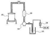
도1은 종래의 반도체장치 제조용 액체공급장치를 나타내는 구성도이다.1 is a block diagram showing a conventional liquid supply apparatus for manufacturing a semiconductor device.
먼저, 탈이온수 또는 케미컬 등과 같은 액체가 수용된 액체용기(10)가 구비되어 있고, 상기 액체용기(10)로부터 액체를 공급받아 저장한 후, 공정수행시 제조설비로 공급하는 액체저장기(12)가 구비되어 있다.First, a
그리고 펌핑동작의 수행으로 상기 액체용기(10)의 액체를 액체저장기(12)로 공급하는 펌프(Pump)(14)가 구비되어 있고, 상기 펌프(14)를 이용하여 상기 액체저장기(12)로 상기 액체를 공급하는 라인 상에는 상기 액체를 여과시키는 필터(16)가 구비되어 있다.In addition, a
또한 질소가스(N2Gas)를 이용하여 상기 액체용기(10)의 액체의 잔유량을 감지하는 감지기(18)가 구비되어 있으며, 이는 상기 질소가스를 상기 액체용기(10)에 수용된 액체의 액면 상으로 방출시켜 상기 액체의 잔류량을 감지한다.In addition, there is a
이러한 구성으로 이루어지는 종래의 액체공급장치는 액체용기(10)의 액체를 필터(16)를 이용하여 여과시키면서 액체저장기(12)로 공급하였다.The conventional liquid supply device having such a configuration is supplied to the
여기서 상기 감지기(18)는 상기 액체의 액면 상으로 방출되는 질소가스를 이용하여 그 잔류량을 감지한다.Here, the
그러나, 상기 질소가스를 방출하는 감지기(18)에 구비되는 튜브(Tube)의 유동으로 인하여 상기 감지기(18)의 오동작이 빈번하게 발생하였다.However, malfunction of the
이에 따라 상기 액체용기(10)에 액체가 잔류하는 상태, 즉 수용된 상태임에도 불구하고 상기 액체용기(10)의 잔류량이 없는 것으로 감지됨으로써 상기 액체용기(10)에 잔류하는 액체를 폐액으로 처리하였다.Accordingly, the liquid remaining in the
또한 상기 질소가스의 방출 및 상기 펌프(14)의 구동으로 인한 기포의 발생으로 상기 액체에 기포가 포함되어 공급되는 경우로 빈번하게 발생하였다.In addition, the air is frequently generated when bubbles are included in the liquid due to the generation of bubbles due to the release of the nitrogen gas and the driving of the
이에 따라 상기 기포로 인하여 상기 액체저장기(12)로 공급되는 과정에서 상기 필터(16)의 수명을 단축시켰고, 또한 상기 필터(16)에 유입된 기포가 파티클(Particle)의 소스(Source)로 작용하였고, 이러한 파티클의 발생으로 인하여 제조공정의 수행시 불량을 야기시켰다.Accordingly, the life of the
따라서 종래의 액체공급장치는 감지기의 오동작 또는 기포의 발생으로 인한 불량 등으로 생산성이 저하되는 문제점이 있었다.Therefore, the conventional liquid supply device has a problem that the productivity is lowered due to a malfunction due to the malfunction of the sensor or the generation of bubbles.
본 발명의 목적은, 액체용기에 수용된 액체의 완전한 공급 및 액체로부터 기포를 분리, 제거시켜 공급함으로써 생산성을 향상시키기 위한 반도체장치 제조용 기포분리기와 이를 적용한 액체공급장치 및 그 구동방법을 제공하는 데 있다.Disclosure of Invention An object of the present invention is to provide a bubble separator for manufacturing a semiconductor device, a liquid supply device using the same, and a driving method thereof for improving productivity by completely supplying a liquid contained in a liquid container and separating and removing bubbles from the liquid. .
도1은 종래의 반도체장치 제조용 액체공급장치를 나타내는 구성도이다.1 is a block diagram showing a conventional liquid supply apparatus for manufacturing a semiconductor device.
도2는 본 발명에 따른 반도체장치 제조용 액체공급장치의 일 실시예를 나타내는 구성도이다.2 is a block diagram showing an embodiment of a liquid supply apparatus for manufacturing a semiconductor device according to the present invention.
도3은 본 발명에 따른 반도체장치 제조용 액체공급장치의 구동방법의 일 실시예를 나타내는 공정도이다.3 is a process diagram showing an embodiment of a method of driving a liquid supply apparatus for manufacturing a semiconductor device according to the present invention.
※도면의 주요부분에 대한 부호의 설명※ Explanation of symbols for main parts of drawing
2 : 기포분리기 10, 20 : 액체용기2:
12, 22 : 액체저장기 14, 30 : 펌프12, 22:
16, 38 : 필터 18, 34 : 감지기16, 38:
24 : 유입구 26 : 액체수용기24: inlet 26: liquid container
28 : 내부관 32 : 부레28: inner tube 32: bure
36 : 배기구36: exhaust port
상기 목적을 달성하기 위한 본 발명에 따른 반도체장치 제조용 기포분리기는, 측벽에 형성된 유입구로부터 유입되는 액체를 수용하는 액체수용기 및 상기 액체수용기 내에 설치되며, 그 하단부가 상기 유입구의 수직위치보다 하방에 위치하여 수용되는 액체에 잠길 수 있는 내부관을 구비하여 이루어짐을 특징으로 한다.The bubble separator for manufacturing a semiconductor device according to the present invention for achieving the above object is provided in the liquid container and the liquid container for receiving the liquid flowing from the inlet formed in the side wall, the lower end is located below the vertical position of the inlet It is characterized by consisting of an inner tube that can be immersed in the liquid received.
상기 액체수용기 및 내부관은 테프론재질로 형성시키는 것이 바람직하다.The liquid container and the inner tube are preferably formed of Teflon material.
상기 액체수용기와 내부관 사이에는 상기 액체의 부력에 의해 동작하는 부레가 더 구비되는 것이 바람직하고, 상기 부레는 그 밑면을 호상형태로 형성시키는 것이 효율적이다.Preferably between the liquid container and the inner tube is provided with a bub which is operated by the buoyancy of the liquid, it is efficient to form the bottom surface in the form of an arc.
상기 부레는 테프론재질로 형성시키는 것이 바람직하다.The bure is preferably formed of a Teflon material.
상기 액체수용기의 상단일측에는 상기 액체로부터 분리되는 기포를 배기시키는 배기구가 더 구비되는 것이 바람직하다.The upper end side of the liquid container is preferably provided with an exhaust port for exhausting the bubbles separated from the liquid.
상기 유입구의 상,하측에는 상기 부레의 동작을 감지하는 감지기가 더 구비되는 것이 바람직하다.The upper and lower sides of the inlet is preferably provided with a detector for detecting the operation of the beret.
본 발명에 따른 반도체장치 제조용 액체공급장치는, 액체용기; 상기 액체용기로부터 액체를 이송시키는 펌핑수단; 상기 펌핑수단에 의해 유입된 액체의 하중을 이용하여 상기 액체로부터 기포를 분리, 제거할 수 있는 기포분리기; 및 상기 기포분리기에 의해 기포가 분리, 제거된 액체를 유입하여 저장하는 액체저장기를 구비하여 이루어짐을 특징으로 한다.Liquid supply apparatus for manufacturing a semiconductor device according to the present invention, a liquid container; Pumping means for transferring liquid from said liquid container; A bubble separator capable of separating and removing bubbles from the liquid by using a load of the liquid introduced by the pumping means; And a liquid reservoir for introducing and storing the liquid separated and removed by the bubble separator.
상기 기포분리기는 측벽에 형성된 유입구로부터 유입되는 액체를 수용하는 액체수용기 및 상기 액체수용기 내에 설치되며, 그 하단부가 상기 유입구의 수직위치보다 하방에 위치하여 수용되는 액체에 잠길 수 있는 내부관으로 이루어지는 것이 바람직하다.The bubble separator is formed of a liquid container for receiving the liquid flowing from the inlet formed in the side wall and an inner tube which is installed in the liquid container, the lower end of which is submerged below the vertical position of the inlet. desirable.
상기 액체수용기와 내부관 사이에는 상기 유입되는 액체의 부력에 의해 동작하는 부레가 구비되고, 상기 액체수용기의 상단일측에는 상기 유입되는 액체로부터 분리되는 기포를 배기시키는 배기구가 더 구비되는 것이 바람직하다.Between the liquid container and the inner tube is provided with a buckle operating by the buoyancy of the incoming liquid, it is preferable that the upper side of the liquid container is further provided with an exhaust port for exhausting the bubbles separated from the incoming liquid.
상기 유입구의 상,하측에는 상기 부레의 동작을 감지하여 상기 펌핑수단 및 배기구를 제어하는 감지기가 더 구비되는 것이 바람직하다.It is preferable that the upper and lower sides of the inlet is further provided with a detector for controlling the pumping means and the exhaust port by detecting the operation of the beret.
상기 기포분리기와 액체저장부 사이에는 상기 액체를 여과시키는 필터가 더 구비되는 것이 바람직하다.It is preferable that a filter for filtering the liquid is further provided between the bubble separator and the liquid storage part.
본 발명에 따른 반도체장치 제조용 액체공급장치의 구동방법은, 측벽에 형성된 유입구로부터 유입되는 액체를 수용할 수 있는 액체수용기 및 상기 액체수용기 내에 설치되며, 그 하단부가 상기 유입구의 수직위치보다 하방에 위치하여 상기 액체수용기로 유입되는 액체에 잠길수 있는 내부관으로 이루어진 기포분리기의 액체수용기로 액체가 유입되는 액체유입단계; 상기 액체수용기로 유입되는 액체의 부력에 의해 상기 액체수용기와 내부관 사이에 형성되는 부레가 동작하는 부레동작단계; 상기 기포분리기의 유입구의 상,하측에 형성되는 감지기를 이용하여 상기 부레의 동작을 감지하는 감지단계; 및 상기 액체를 기포분리기의 액체수용기로 유입시키는 펌프 및 상기 유입되는 액체로부터 분리되는 기포를 배기시킬 수 있도록 상기 액체수용기의 상단일측에 형성되는 배기부를 상기 감지기의 신호입력에 의해 제어하는 제어단계를 구비하여 이루어짐을 특징으로 한다.In the method of driving a liquid supply apparatus for manufacturing a semiconductor device according to the present invention, a liquid container capable of receiving a liquid flowing from an inlet formed in a sidewall thereof is provided in the liquid container, and a lower end thereof is positioned below a vertical position of the inlet. A liquid inflow step of introducing liquid into the liquid container of the bubble separator having an inner tube which can be immersed in the liquid introduced into the liquid container; A boolean operation step in which a bub formed between the liquid container and the inner tube is operated by buoyancy of the liquid introduced into the liquid container; Sensing step of detecting the operation of the bure using a sensor formed on the upper, lower side of the inlet of the bubble separator; And a control step of controlling a pump for introducing the liquid into the liquid container of the bubble separator and an exhaust part formed at one side of the upper end of the liquid container so as to exhaust the bubbles separated from the incoming liquid. Characterized in that it is made.
이하, 본 발명의 구체적인 실시예를 첨부한 도면을 참조하여 상세히 설명한다.Hereinafter, exemplary embodiments of the present invention will be described in detail with reference to the accompanying drawings.
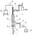
도2는 본 발명에 따른 반도체장치 제조용 액체공급장치의 일 실시예를 나타내는 구성도이고, 도3은 본 발명에 따른 반도체장치 제조용 액체공급장치의 구동방법의 일 실시예를 나타내는 공정도이다.2 is a block diagram showing an embodiment of a liquid supply apparatus for manufacturing a semiconductor device according to the present invention, Figure 3 is a process diagram showing an embodiment of a method of driving a liquid supply apparatus for manufacturing a semiconductor device according to the present invention.
먼저, 도2는 반도체장치의 제조공정에 이용되는 액체 즉, 탈이온수 또는 케미컬 등이 수용된 액체용기(20) 및 상기 액체용기(20)의 액체를 공급받아 저장한 후, 공정수행시 각 제조설비들로 상기 액체를 공급하는 액체저장기(22)가 구비되어 있다.First, FIG. 2 is supplied with a
여기서 본 발명의 상기 액체저장기(22)는 중앙공급방식의 저장탱크인 것이 효율적이다.Wherein the
그리고 본 발명은 상기 액체용기(20)에 수용된 액체를 유입받는 유입구(24)가 그 측벽에 구비되는 액체수용기(26) 및 상기 액체수용기(26) 내에 설치되며, 그 하단부가 상기 유입구(24)의 수직위치보다 하방에 위치하여 상기 액체수용기(26)로 수용되는 액체에 잠길 수 있는 내부관(28)으로 이루어지는 기포분리기(2)가 상기 액체용기(20)와 액체저장기(22) 사이에 구비되어 있다.And the present invention is installed in the
여기서 상기 기포분리기(2)는 상기 액체의 하중을 이용하여 상기 액체로부터 기포를 분리, 제거시키는 것으로써, 상기 액체수용기(26)의 저면에 드롭(Drop)되는 액체를 상기 내부관(28)을 통하여 상기 액체저장부(22)로 공급한다.Here, the
즉, 본 발명은 상기 액체용기(20)와 액체저장기(22) 사이에 상기 기포분리기(2)를 연결, 구비시켜 상기 액체의 공급시 상기 액체로부터 기포를 분리, 제거시켜 공급한다.That is, the present invention connects and includes the
여기서 상기 액체수용기(26) 및 내부관(28) 등으로 이루어지는 기포분리기(2)는 합성수지인 테프론수지(Teflon Resin)로 형성시킬 수 있다.Here, the
그리고 상기 액체용기(20)에 수용된 액체는 상기 액체를 펌핑하여 유입시키는 펌핑수단인 펌프(30)를 이용하여 공급한다.The liquid contained in the
또한 본 발명은 상기 액체수용기(26)의 저면으로 드롭되는 액체의 부력으로 동작하는 부표수단인 부레(Float)(32)를 상기 액체수용기(26)과 내부관(28) 사이에 구비시킨다.In addition, the present invention is provided between the
여기서 상기 부레(32)는 테프론수지 등으로 형성할 수 있고, 부유압을 향상시키기 위하여 그 밑면을 호상형태로 형성시킨다.Here, the
그리고 본 발명의 상기 유입구(24)의 상, 하측에는 상기 부레(32)의 동작을 감지하는 감지수단인 감지기(34)를 구비시키고, 또한 상기 액체수용기(26)의 상단일측에는 상기 액체로부터 분리되는 기포를 배기시키는 배기수단인 배기구(36)를 구비시킨다.And the upper and lower sides of the
여기서 상기 배기구(36)는 파이프(Pipe) 및 상기 파이프 상에 구비되는 밸브(Valve)로 이루어진다.The
그리고 상기 배기구(36)는 상기 감지부(34)의 신호입력으로 개폐동작을 수행한다.In addition, the
이에 따라 상기 감지기(34)를 이용하여 상기 액체의 유입량을 제어하고, 또한 상기 감지기(34)의 신호입력으로 상기 배기부(36)의 밸브가 개폐동작을 수행하여 상기 액체로부터 분리되는 기포를 제거시키기 위하여 외부로 배기시킨다.Accordingly, the flow rate of the liquid is controlled by using the
그리고 본 발명은 상기 기포분리기(2)의 내부관(28)을 통하여 상기 액체저장기(22)로 공급되는 액체를 여과시키는 여과수단인 필터(38)를 상기 기포분리기(2)와 액체저장기(22)의 라인 상에 구비시킨다.In addition, the present invention provides a
즉, 본 발명은 상기 필터(38)를 구비시켜 상기 액체를 여과 즉, 정제시켜면서 상기 액체저장기(22)로 공급시킨다.That is, according to the present invention, the
이러한 구성으로 이루어지는 본 발명은 상기 액체의 하중을 이용하여 상기 액체로부터 기포를 분리, 제거시켜 공급함으로써 상기 기포로 인하여 발생되는 파티클로 인한 불량을 방지할 수 있고, 또한 여과수단인 필터(38) 등의 수명을 연장시킬 수 있다.The present invention having such a configuration can prevent defects caused by particles caused by the bubbles by separating, removing and supplying bubbles from the liquid by using the load of the liquid, and also filter 38 as a filtration means. Can extend the life of the product.
그리고 본 발명은 상기 감지기(34)를 기포분리기(2)의 외부에 구비시킴으로써 상기 액체의 공급시 상기 감지기(34)의 오동작 등을 방지할 수 있다.And the present invention can be provided to the outside of the
이에 따라 상기 액체용기(20)의 액체를 완전하게 상기 액체저장기(22)로 공급할 수 있음으로 인해 상기 액체용기(20)에 액체가 수용된 상태에서 교환되는 것을 방지할 수 있고, 상기 감지기(34)의 오동작 등으로 인한 불량을 방지할 수 있다.Accordingly, since the liquid in the
전술한 구성으로 이루어지는 본 발명의 구체적인 실시예에 대한 작용 및 효과에 대하여 설명한다.Actions and effects of specific embodiments of the present invention having the above-described configuration will be described.
본 발명은 액체저장기(22)에 상기 액체를 공급하기 위하여 먼저, 상기 액체가 수용된 액체용기(20)를 이송하여 상기 유입구의 라인 상에 연결시킨다.In the present invention, in order to supply the liquid to the
그리고 상기 펌프(30)의 펌핑동작의 수행으로 상기 액체를 기포분리기(2)의 액체수용기(26)로 유입시킨다.The liquid is introduced into the
이렇게 액체수용기(26)로 유입된 상기 액체는 상기 액체수용기(26)의 저면으로 드롭된다.The liquid introduced into the
여기서 상기 액체수용기(26)로 유입되는 액체는 상기 액체가 드롭되는 시점인 유입구(24)의 단부에서 상기 액체로부터 기포를 분리시키면서 상기 액체수용기(26)의 저면으로 드롭된다.Herein, the liquid flowing into the
즉, 상기 펌프(30)의 펌핑 등으로 발생되는 기포가 포함된 액체의 하중을 이용하여 상기 액체로부터 상기 기포를 분리, 제거시킨다.That is, the bubble is separated and removed from the liquid by using the load of the liquid containing bubbles generated by the pumping of the
이렇게 상기 액체에서 분리, 제거된 기포는 상기 배기구(36)를 통하여 외부로 배기된다.The bubbles separated and removed in the liquid are exhausted to the outside through the
그리고 본 발명은 상기 액체의 하중으로 동작하는 부레(32) 및 상기 부레(32)의 동작을 감지하는 감지기(34)를 이용하여 상기 기포를 외부로 배기시키는 배기구(36)를 제어한다.In addition, the present invention controls the
또한 상기 감지기(34)는 상기 펌프(30) 등을 제어하여 상기 기포분리기(2)의 액체수용기(26)로 유입되는 액체의 유입량을 제어한다.In addition, the
즉, 상기 부레(32)가 유입구(24)의 하측에서 감지되었을 때에는 상기 배기구(36)를 폐쇄시키고 상기 펌프(30)는 계속적인 펌핑을 수행하며, 한편 상기 부레(32)가 공급관(24)의 상측에서 감지되었을 때에는 상기 배기구(36)는 개방되어 상기 액체로부터 분리된 기포를 외부로 배기시키고 상기 펌프(30)는 펌핑동작을 멈추어서 상기 액체의 유입을 중단시킨다.That is, when the
이에 따라 기포가 분리, 제거된 상기 액체는 내부관(28)을 통하여 상기 액체저장기(22)로 공급된다.Accordingly, the liquid from which the bubbles are separated and removed is supplied to the
여기서 상기 내부관(28)를 통하여 상기 액체저장기(22)로 공급되는 라인 상에 구비되는 여과수단인 필터(38)를 이용하여 상기 액체를 여과 즉, 정제시키면서 공급한다.Here, the liquid is supplied while being filtered, i.e., purified, using a
이에 따라 본 발명은 기포를 분리시켜 공급되는 액체를 상기 액체저장부(22)에 저장시킨 후, 공정수행시 각 제조설비들로 상기 액체를 공급한다.Accordingly, the present invention stores the liquid supplied by separating the bubbles in the
이러한 구성으로 이루어지는 본 발명은 상기 액체의 유입량 등을 제어하는 감지기(34)를 상기 기포분리기(2)의 외부에 구비시킴으로써 상기 감지기(34)의 오동작을 미연에 방지하여 상기 감지기(34)의 오동작으로 인한 불량을 방지할 수 있다.The present invention having such a configuration is provided with a
이에 따라 상기 액체용기(20)에 액체가 수용된 상태에서 교환되는 것을 방지할 수 있음으로 인해 상기 액체의 폐액발생 등을 감소시킬 수 있다.Accordingly, since the liquid can be prevented from being exchanged in the
또한 본 발명은 상기 기포분리기(2)를 이용함으로써 상기 액체를 기포가 분리, 제거된 상태로 공급할 수 있음으로 인해 상기 기포로 인한 불량을 방지할 수 있다.In addition, the present invention can prevent the defect caused by the bubbles due to the bubble separator (2) can be supplied in a state in which the bubble is separated, removed.
즉, 상기 기포로 인한 파티클의 발생 등을 방지할 수 있고, 또한 상기 여과수단인 필터(38) 등의 수명을 연장시킬 수 있다.That is, generation of particles due to the bubbles can be prevented, and the life of the
이에 따라 본 발명은 용기부의 액체를 기포가 분리, 제거된 상태로 완전하게 액체저장기(22)로 공급할 수 있다.Accordingly, in the present invention, the liquid in the container portion can be completely supplied to the
따라서, 본 발명에 의하면 감지부의 오동작의 방지를 통하여 이로 인한 불량을 억제시키고, 또한 기포를 분리, 제거시킨 액체를 공급함으로써 생산성이 향상되는 효과가 있다.Therefore, according to the present invention, it is possible to suppress the malfunction caused by the malfunction of the sensing unit and to improve the productivity by supplying a liquid in which bubbles are separated and removed.
이상에서 본 발명은 기재된 구체예에 대해서만 상세히 설명되었지만 본 발명의 기술사상 범위 내에서 다양한 변형 및 수정이 가능함은 당업자에게 있어서 명백한 것이며, 이러한 변형 및 수정이 첨부된 특허청구범위에 속함은 당연한 것이다.Although the present invention has been described in detail only with respect to the described embodiments, it will be apparent to those skilled in the art that various modifications and variations are possible within the technical scope of the present invention, and such modifications and modifications are within the scope of the appended claims.
Claims (4)
Translated fromKoreanPriority Applications (3)
| Application Number | Priority Date | Filing Date | Title |
|---|---|---|---|
| KR1019970037367AKR100280011B1 (en) | 1997-08-05 | 1997-08-05 | Bubble separator for manufacturing semiconductor device, liquid supply device using same and driving method thereof |
| TW087106018ATW447005B (en) | 1997-08-05 | 1998-04-20 | Bubble separator for manufacturing semiconductor devices and apparatus for supplying liquid and its driving method thereby |
| JP12336598AJP4042875B2 (en) | 1997-08-05 | 1998-05-06 | Bubble separator for manufacturing semiconductor device, processing liquid supply device for manufacturing semiconductor device using the same, and driving method thereof |
Applications Claiming Priority (1)
| Application Number | Priority Date | Filing Date | Title |
|---|---|---|---|
| KR1019970037367AKR100280011B1 (en) | 1997-08-05 | 1997-08-05 | Bubble separator for manufacturing semiconductor device, liquid supply device using same and driving method thereof |
Publications (2)
| Publication Number | Publication Date |
|---|---|
| KR19990015330A KR19990015330A (en) | 1999-03-05 |
| KR100280011B1true KR100280011B1 (en) | 2001-03-02 |
Family
ID=19516911
Family Applications (1)
| Application Number | Title | Priority Date | Filing Date |
|---|---|---|---|
| KR1019970037367AExpired - Fee RelatedKR100280011B1 (en) | 1997-08-05 | 1997-08-05 | Bubble separator for manufacturing semiconductor device, liquid supply device using same and driving method thereof |
Country Status (3)
| Country | Link |
|---|---|
| JP (1) | JP4042875B2 (en) |
| KR (1) | KR100280011B1 (en) |
| TW (1) | TW447005B (en) |
Cited By (1)
| Publication number | Priority date | Publication date | Assignee | Title |
|---|---|---|---|---|
| KR100502161B1 (en)* | 1998-05-19 | 2005-11-21 | 삼성전자주식회사 | Device for filtering liquid |
Families Citing this family (7)
| Publication number | Priority date | Publication date | Assignee | Title |
|---|---|---|---|---|
| KR100580873B1 (en)* | 1999-06-17 | 2006-05-16 | 엘지.필립스 엘시디 주식회사 | Etching Device |
| BR0109283A (en) | 2000-03-14 | 2002-12-17 | James Hardie Res Pty Ltd | Fiber cement construction materials containing low density additives |
| KR100394274B1 (en)* | 2001-10-12 | 2003-08-09 | 금호산업주식회사 | A Container of Storing Dipping Solution Without Overflow |
| KR100812146B1 (en)* | 2001-10-31 | 2008-03-12 | 주식회사 포스코 | Defoamer of organic coating resin solution tank |
| US7452408B2 (en)* | 2005-06-30 | 2008-11-18 | Lam Research Corporation | System and method for producing bubble free liquids for nanometer scale semiconductor processing |
| KR101423161B1 (en)* | 2012-11-13 | 2014-07-28 | 국방과학연구소 | Removing bubble apparatus for liquid having bubble, and removing bubble and vaporizing liquid apparatus for liquid having bubble, and removing bubble method for liquid having bubble, and removing bubble and vaporizing liquid method for liquid having bubble |
| JP2022017131A (en)* | 2020-07-13 | 2022-01-25 | 株式会社ジェイ・イー・ティ | Cell unit, measuring device, and board processing device |
- 1997
- 1997-08-05KRKR1019970037367Apatent/KR100280011B1/ennot_activeExpired - Fee Related
- 1998
- 1998-04-20TWTW087106018Apatent/TW447005B/ennot_activeIP Right Cessation
- 1998-05-06JPJP12336598Apatent/JP4042875B2/ennot_activeExpired - Fee Related
Cited By (1)
| Publication number | Priority date | Publication date | Assignee | Title |
|---|---|---|---|---|
| KR100502161B1 (en)* | 1998-05-19 | 2005-11-21 | 삼성전자주식회사 | Device for filtering liquid |
Also Published As
| Publication number | Publication date |
|---|---|
| JP4042875B2 (en) | 2008-02-06 |
| TW447005B (en) | 2001-07-21 |
| JPH1167715A (en) | 1999-03-09 |
| KR19990015330A (en) | 1999-03-05 |
Similar Documents
| Publication | Publication Date | Title |
|---|---|---|
| KR101750647B1 (en) | Liquid supply device and substrate processing device | |
| KR100280011B1 (en) | Bubble separator for manufacturing semiconductor device, liquid supply device using same and driving method thereof | |
| KR102298519B1 (en) | Water treatment membrane cleaning device and cleaning method | |
| KR20130094755A (en) | Liquid treatment method and removal system of gas in filter | |
| KR100372671B1 (en) | Wet processing device | |
| JPH0231785Y2 (en) | ||
| KR100598914B1 (en) | Chemical liquid regeneration system and chemical liquid regeneration method, and substrate processing equipment having the system | |
| KR20140047636A (en) | Liquid photoresist supply equipment | |
| KR100330715B1 (en) | Oil recovery system | |
| KR101976429B1 (en) | Photoresist bubble clear reclaim supply system | |
| JP4341185B2 (en) | Chemical manufacturing equipment | |
| JPH11121422A (en) | Chemical supply device | |
| JPH0857211A (en) | Regeneration of filter medium in filter | |
| JP4262568B2 (en) | Oil / water separator | |
| KR100697047B1 (en) | Device and method for separating foreign matters generated during wafer or substrate cleaning | |
| KR19990051324A (en) | Liquid supply device for semiconductor device manufacturing | |
| KR102574827B1 (en) | Backwashing device for water treatment | |
| JPH08266815A (en) | Filter medium transfer device in moving filter bed type filter | |
| KR200153640Y1 (en) | Photoresist supplying apparatus | |
| KR100664779B1 (en) | Photo Resist Supply | |
| KR101398861B1 (en) | Chemical reproduction device and reproduction method | |
| CN100400135C (en) | Method and system for separating sediment by photoelectric technology | |
| KR20050106663A (en) | System for supplying liquid state chemicals of semiconductor manufacturing process | |
| JP2555971B2 (en) | Chemical supply device and control method thereof | |
| JPH044811Y2 (en) |
Legal Events
| Date | Code | Title | Description |
|---|---|---|---|
| A201 | Request for examination | ||
| PA0109 | Patent application | St.27 status event code:A-0-1-A10-A12-nap-PA0109 | |
| PA0201 | Request for examination | St.27 status event code:A-1-2-D10-D11-exm-PA0201 | |
| R17-X000 | Change to representative recorded | St.27 status event code:A-3-3-R10-R17-oth-X000 | |
| R18-X000 | Changes to party contact information recorded | St.27 status event code:A-3-3-R10-R18-oth-X000 | |
| PN2301 | Change of applicant | St.27 status event code:A-3-3-R10-R13-asn-PN2301 St.27 status event code:A-3-3-R10-R11-asn-PN2301 | |
| PG1501 | Laying open of application | St.27 status event code:A-1-1-Q10-Q12-nap-PG1501 | |
| PN2301 | Change of applicant | St.27 status event code:A-3-3-R10-R13-asn-PN2301 St.27 status event code:A-3-3-R10-R11-asn-PN2301 | |
| E902 | Notification of reason for refusal | ||
| PE0902 | Notice of grounds for rejection | St.27 status event code:A-1-2-D10-D21-exm-PE0902 | |
| AMND | Amendment | ||
| P11-X000 | Amendment of application requested | St.27 status event code:A-2-2-P10-P11-nap-X000 | |
| P13-X000 | Application amended | St.27 status event code:A-2-2-P10-P13-nap-X000 | |
| R17-X000 | Change to representative recorded | St.27 status event code:A-3-3-R10-R17-oth-X000 | |
| E601 | Decision to refuse application | ||
| PE0601 | Decision on rejection of patent | St.27 status event code:N-2-6-B10-B15-exm-PE0601 | |
| J201 | Request for trial against refusal decision | ||
| PJ0201 | Trial against decision of rejection | St.27 status event code:A-3-3-V10-V11-apl-PJ0201 | |
| R18-X000 | Changes to party contact information recorded | St.27 status event code:A-3-3-R10-R18-oth-X000 | |
| AMND | Amendment | ||
| P11-X000 | Amendment of application requested | St.27 status event code:A-2-2-P10-P11-nap-X000 | |
| P13-X000 | Application amended | St.27 status event code:A-2-2-P10-P13-nap-X000 | |
| PB0901 | Examination by re-examination before a trial | St.27 status event code:A-6-3-E10-E12-rex-PB0901 | |
| B701 | Decision to grant | ||
| PB0701 | Decision of registration after re-examination before a trial | St.27 status event code:A-3-4-F10-F13-rex-PB0701 | |
| GRNT | Written decision to grant | ||
| PR0701 | Registration of establishment | St.27 status event code:A-2-4-F10-F11-exm-PR0701 | |
| PR1002 | Payment of registration fee | St.27 status event code:A-2-2-U10-U11-oth-PR1002 Fee payment year number:1 | |
| PG1601 | Publication of registration | St.27 status event code:A-4-4-Q10-Q13-nap-PG1601 | |
| PN2301 | Change of applicant | St.27 status event code:A-5-5-R10-R13-asn-PN2301 St.27 status event code:A-5-5-R10-R11-asn-PN2301 | |
| R18-X000 | Changes to party contact information recorded | St.27 status event code:A-5-5-R10-R18-oth-X000 | |
| R18-X000 | Changes to party contact information recorded | St.27 status event code:A-5-5-R10-R18-oth-X000 | |
| PR1001 | Payment of annual fee | St.27 status event code:A-4-4-U10-U11-oth-PR1001 Fee payment year number:4 | |
| R18-X000 | Changes to party contact information recorded | St.27 status event code:A-5-5-R10-R18-oth-X000 | |
| PR1001 | Payment of annual fee | St.27 status event code:A-4-4-U10-U11-oth-PR1001 Fee payment year number:5 | |
| PN2301 | Change of applicant | St.27 status event code:A-5-5-R10-R13-asn-PN2301 St.27 status event code:A-5-5-R10-R11-asn-PN2301 | |
| PN2301 | Change of applicant | St.27 status event code:A-5-5-R10-R13-asn-PN2301 St.27 status event code:A-5-5-R10-R11-asn-PN2301 | |
| PR1001 | Payment of annual fee | St.27 status event code:A-4-4-U10-U11-oth-PR1001 Fee payment year number:6 | |
| PR1001 | Payment of annual fee | St.27 status event code:A-4-4-U10-U11-oth-PR1001 Fee payment year number:7 | |
| PR1001 | Payment of annual fee | St.27 status event code:A-4-4-U10-U11-oth-PR1001 Fee payment year number:8 | |
| PR1001 | Payment of annual fee | St.27 status event code:A-4-4-U10-U11-oth-PR1001 Fee payment year number:9 | |
| PR1001 | Payment of annual fee | St.27 status event code:A-4-4-U10-U11-oth-PR1001 Fee payment year number:10 | |
| PR1001 | Payment of annual fee | St.27 status event code:A-4-4-U10-U11-oth-PR1001 Fee payment year number:11 | |
| PR1001 | Payment of annual fee | St.27 status event code:A-4-4-U10-U11-oth-PR1001 Fee payment year number:12 | |
| R18-X000 | Changes to party contact information recorded | St.27 status event code:A-5-5-R10-R18-oth-X000 | |
| FPAY | Annual fee payment | Payment date:20121031 Year of fee payment:13 | |
| PR1001 | Payment of annual fee | St.27 status event code:A-4-4-U10-U11-oth-PR1001 Fee payment year number:13 | |
| FPAY | Annual fee payment | Payment date:20131031 Year of fee payment:14 | |
| PR1001 | Payment of annual fee | St.27 status event code:A-4-4-U10-U11-oth-PR1001 Fee payment year number:14 | |
| LAPS | Lapse due to unpaid annual fee | ||
| PC1903 | Unpaid annual fee | St.27 status event code:A-4-4-U10-U13-oth-PC1903 Not in force date:20141107 Payment event data comment text:Termination Category : DEFAULT_OF_REGISTRATION_FEE | |
| PC1903 | Unpaid annual fee | St.27 status event code:N-4-6-H10-H13-oth-PC1903 Ip right cessation event data comment text:Termination Category : DEFAULT_OF_REGISTRATION_FEE Not in force date:20141107 | |
| P22-X000 | Classification modified | St.27 status event code:A-4-4-P10-P22-nap-X000 |