KR100265362B1 - Data Transmission / Reception Method of Microprocessor Using Serial Parallel Method - Google Patents
Data Transmission / Reception Method of Microprocessor Using Serial Parallel MethodDownload PDFInfo
- Publication number
- KR100265362B1 KR100265362B1KR1019970077873AKR19970077873AKR100265362B1KR 100265362 B1KR100265362 B1KR 100265362B1KR 1019970077873 AKR1019970077873 AKR 1019970077873AKR 19970077873 AKR19970077873 AKR 19970077873AKR 100265362 B1KR100265362 B1KR 100265362B1
- Authority
- KR
- South Korea
- Prior art keywords
- data
- microprocessor
- bus
- bits
- parallel
- Prior art date
- Legal status (The legal status is an assumption and is not a legal conclusion. Google has not performed a legal analysis and makes no representation as to the accuracy of the status listed.)
- Expired - Fee Related
Links
Images


Classifications
- G—PHYSICS
- G06—COMPUTING OR CALCULATING; COUNTING
- G06F—ELECTRIC DIGITAL DATA PROCESSING
- G06F13/00—Interconnection of, or transfer of information or other signals between, memories, input/output devices or central processing units
- G06F13/38—Information transfer, e.g. on bus
- G—PHYSICS
- G06—COMPUTING OR CALCULATING; COUNTING
- G06F—ELECTRIC DIGITAL DATA PROCESSING
- G06F13/00—Interconnection of, or transfer of information or other signals between, memories, input/output devices or central processing units
- G06F13/38—Information transfer, e.g. on bus
- G06F13/40—Bus structure
- G06F13/4004—Coupling between buses
- G06F13/4009—Coupling between buses with data restructuring
- G06F13/4018—Coupling between buses with data restructuring with data-width conversion
Landscapes
- Engineering & Computer Science (AREA)
- Theoretical Computer Science (AREA)
- General Engineering & Computer Science (AREA)
- Physics & Mathematics (AREA)
- General Physics & Mathematics (AREA)
- Computer Hardware Design (AREA)
- Microcomputers (AREA)
- Information Transfer Systems (AREA)
- Memory System (AREA)
- Dram (AREA)
Abstract
Translated fromKoreanDescription
Translated fromKorean본 발명은 컴퓨터에서 CPU로 사용되는 마이크로프로세서의 시리얼 버스(serial bus)를 운영한 데이터 송수신 방법에 관한 것으로서, 특히 마이크로프로세서에서 병렬식으로 데이터를 처리할 때 야기되는 핀수의 한계를 극복하기 위해서 데이터를 직병렬 방식으로 처리하기 위한 방법에 관한 것이다.The present invention relates to a method for transmitting and receiving data operating a serial bus of a microprocessor used as a CPU in a computer, and in particular, to overcome the limitation of the number of pins caused when processing data in parallel in a microprocessor. It relates to a method for processing the in a serial to parallel manner.
마이크로프로세서는 주로 컴퓨터의 CPU로 사용되고 있는데, 마이크로 명령을 실제로 실행하는 1개 또는 여러 개의 대규모 집적회로(LSI)로 이루어진 전자회로를 말하며, 연산기능, 기억기능, 제어기능 등을 가지고 있는 것으로서 원-칩(one-chip)화 되어 있다. 대표적인 마이크로프로세서로는 인텔사의 펜티엄(Pentium), 펜티엄 프로(Pentium Pro)등과 모토롤라 사의 63000 계열의 마이크로프로세서들이 있다.A microprocessor is mainly used as a computer's CPU. It is an electronic circuit composed of one or several large integrated circuits (LSIs) that actually execute micro instructions, and has arithmetic, memory, and control functions. It is one-chip. Typical microprocessors include Intel's Pentium, Pentium Pro, and Motorola's 63000 series of microprocessors.
마이크로프로세서의 발전사를 보면, 최초에는 4비트 데이터를 처리할 수 있도록 설계되었다. 그후 점차 한번에 처리할 수 있는 데이터 크기를 늘려서 8비트, 16비트 마이크로프로세서로 발전해 왔으며, 현재는 32비트 마이크로프로세서가 주로 사용되고 있다. 고성능 마이크로프로세서로서 이미 64비트 마이크로프로세서도 개발되어 사용되고 있는 실정이다. 뿐만 아니라 그래픽 전용 마이크로프로세서들은 128비트 데이터를 한번에 처리할 수 있도록 개발되어 사용되기도 한다.Looking at the evolution of microprocessors, they were initially designed to handle 4-bit data. Since then, it has gradually evolved into an 8-bit and 16-bit microprocessor by increasing the size of data that can be processed at one time. Today, 32-bit microprocessors are mainly used. As a high performance microprocessor, a 64-bit microprocessor has already been developed and used. In addition, graphics-only microprocessors are developed and used to process 128-bit data at once.
이처럼 마이크로프로세서의 발전사를 보면 한번에 처리할 수 있는 데이터의 크기를 늘리는 것이 관건이 되었음을 알 수 있다. 이와 같이 일시에 처리하는 데이터의 수를 늘림으로써 마이크로프로세서의 성능을 크게 개선시킬 수 있기 때문이다. 따라서 향후 128비트, 256비트 마이크로프로세서가 계속 개발될 전망이다.The evolution of microprocessors suggests that increasing the size of data that can be processed at one time has been a challenge. This is because the performance of the microprocessor can be greatly improved by increasing the number of data processed at one time. Therefore, 128-bit and 256-bit microprocessors will continue to be developed.
그러나 이처럼 마이크로프로세서가 발전함에 따라서 중요한 문제점이 하나 대두된다. 즉, 한번에 처리할 수 있는 데이터의 크기만큼(일시에 처리할 수 있는 데이터의 비트 수만큼) 마이크로프로세서에서 나오는 버스(bus)가 외부 메모리 모듈과 연결되어야 하는데, 마이크로프로세서의 패키징(packaging)시에 부착할 수 있는 핀(pin)의 수가 제한되어 있기 때문에 데이터의 크기를 늘리는데 한계점에 이르게 되는 것이다. 예를 들어 256비트 마이크로프로세서의 경우에 데이터 버스만 외부로 연결시켜도 256개의 핀이 필요하다. 또한 어드레스 버스를 64비트만 사용한다 할지라도 도합 300개의 핀이 필요하게 된다. 이러한 핀 숫자는 현재의 패키징 기술로 하나의 패키지에서 설치할 수 있는 최대의 핀수에 가까운 숫자이다. 마이크로프로세서가 동작하는데는 이러한 데이터 버스와 어드레스 버스 외에도 많은 제어 핀들이 필요하기 때문에 현재와 같은 방법으로 버스를 그대로 외부 핀으로 사용하는 방법으로는 더 이상의 데이터 처리 용량을 증가시킬 수 없다는 결론에 이르게 된다.However, as the microprocessor develops, an important problem arises. That is, as much as the data that can be processed at one time (the number of bits of data that can be processed at one time), a bus from the microprocessor must be connected to an external memory module. Because of the limited number of pins you can attach, you're reaching your limit in increasing the size of your data. For example, a 256-bit microprocessor requires 256 pins, even if only the data bus is externally connected. In addition, even if the address bus uses only 64 bits, a total of 300 pins are required. These pin numbers are close to the maximum number of pins that can be installed in one package with current packaging technology. Since the microprocessor requires many control pins in addition to these data buses and address buses, it is concluded that using the bus as an external pin in the present way cannot increase the data processing capacity any further. .
본 발명은 이와 같이 마이크로프로세서의 핀을 늘리는데 따른 한계로 인해서 데이터 처리 용량을 확장시킬 수 없다는 문제점을 해결하기 위한 것으로서, 현재의 마이크로프로세서 데이터 버스 및 어드레스 버스가 완전히 병렬 버스 방식인 것을 개선하여 병렬 버스에 직렬 버스 방식을 도입하여 적은 핀으로도 대용량의 데이터를 처리하도록 하는 것을 목적으로 한다.The present invention is to solve the problem that the data processing capacity can not be expanded due to the limitation of increasing the pins of the microprocessor. The present invention improves that the current microprocessor data bus and address bus are completely parallel buses. Its purpose is to introduce a serial bus method to handle large amounts of data with only a few pins.
이를 위해서 본 발명에서는 데이터 버스 및 어드레스 버스가 완전히 병렬 버스 방식인 것을 개선하여 병렬 버스에 직렬 버스의 동작 방식을 도입하여 직병렬식으로 데이터를 처리하도록 하였다. 예를 들어 설명하면, 한번에 처리할 수 있는 데이터의 크기가 256 비트라고 가정했을 때 종래의 완전 병렬 버스 방식으로 데이터를 전송하기 위해서는 마이크프로세서의 외부 패키지에 256개의 핀이 필요하게 된다. 그러나 본 발명의 원리를 적용하게 되면 패키지의 핀수를 줄일 수가 있다. 즉, 본 발명의 원리를 사용하여 256 비트를 한번에 전송하는 것이 아니고, 이를 4번에 나누어서 전송한다고 가정하게 되면, 64 비트를 4회에 걸쳐서 전송이 가능하게 된다. 한번에 64비트의 데이터를 전송하는 것은 종래의 방식대로 병렬 버스 방식으로 하고, 이러한 과정을 4회에 걸쳐서 수행하는 것은 직렬 식으로 하는 것이다.To this end, the present invention improves that the data bus and the address bus are completely parallel buses, and introduces a serial bus operation method to the parallel buses to process data in parallel and parallel manners. For example, assuming that the size of data that can be processed at one time is 256 bits, 256 pins are required in an external package of the microprocessor in order to transmit data using the conventional all-parallel bus method. However, applying the principles of the present invention can reduce the pin count of the package. In other words, assuming that 256 bits are not transmitted at once using the principles of the present invention, but are divided into four transmissions, 64 bits can be transmitted four times. Transferring 64-bit data at a time is in parallel bus fashion, and performing this process four times is in serial fashion.
이와 같이 하므로 마이크로프로세서의 외부 패키지로 나오는 핀은 실제로 64개만 사용해도 충분하게 된다. 즉, 64개의 핀 만으로도 256 비트의 데이터를 성공적으로 전송할 수 있게 된다.In doing so, it is enough to actually use only 64 pins coming out of the microprocessor's external package. That is, only 64 pins can successfully transmit 256 bits of data.
이처럼 본 발명의 원리를 사용하게 되면 일반적인 마이크로프로세서에서 어떠한 길이의 데이터도 전송이 가능하게 된다. 말하자면, m 이 n 보다 작은 수이며, n 이 m 으로 나누어서 나머지가 0 이 되는 수라고 가정할 때, 즉, m 이 n 의 약수일 때, n 비트의 데이터 처리 용량을 갖는 마이크로프로세서에서 m 개의 핀만을 외부 패키지로 빼내서 사용이 가능하다. 이때 한번에 전송되는 데이터의 용량은 핀수인 m 비트이며, 마이크로프로세서의 데이터 처리 용량인 n 비트를 처리하는데는 n을 m 으로 나눈 몫(n/m) 만큼의 횟수에 걸쳐서 반복되어 수행된다.As such, using the principles of the present invention, it is possible to transmit data of any length in a general microprocessor. In other words, assuming that m is a number less than n and n is divided by m and the remainder is zero, that is, m is a divisor of n, m pins in a microprocessor with n bits of data processing capacity. Only bay can be taken out of the package. At this time, the capacity of data transmitted at one time is m bits, which is the number of pins, and the processing of n bits, which is the data processing capacity of the microprocessor, is repeatedly performed over the number of times n divided by m (n / m).
본 발명에서 데이터 버스와 어드레스 버스를 공유하게 되는 경우, 패키지의 밖으로 빼내는 핀수는 어드레스 버스의 수보다 크게 했을 때 최적의 효율을 얻을 수 있다. 어드레스 버스가 32 비트만 되어도 4 기가 바이트의 메모리 영역을 참조할 수 있기 때문에 마이크로프로세서가 한번에 처리할 수 있는 데이터의 용량이 점점 커진다 할지라도 어드레스 비트의 수를 늘릴 이유는 특별히 없다. 따라서 향후 128 비트, 256 비트, 512 비트 등의 마이크로프로세서가 개발된다 할지라도 어드레스 버스의 크기는 32 비트 또는 64 비트로 머물러 있을 가능성이 크다. 따라서 앞으로 대부분의 경우에 어드레스 버스가 데이터 버스의 크기보다는 작을 것이다. 따라서 어드레스 버스의 비트 수 보다 크거나 같으면서 데이터 버스 비트 수 보다는 작은 2의 배수를 택하여 어드레스 및 데이터 핀으로 사용하면 최적의 효율을 얻을 것을 기대할 수 있다. 그 이유는 어드레스를 한번에 외부 메모리 모듈로 전송할 수 있기 때문에 외부 메모리 버스 사이클을 줄일 수 있기 때문이다.In the present invention, when the data bus and the address bus are shared, an optimum efficiency can be obtained when the number of pins taken out of the package is larger than the number of address buses. Since only 32 bits of address bus can refer to 4 gigabytes of memory, there is no reason to increase the number of address bits even if the amount of data that the microprocessor can process at one time becomes larger. Therefore, even if microprocessors such as 128-bit, 256-bit, and 512-bit are developed in the future, the size of the address bus is likely to remain 32-bit or 64-bit. Thus, in most cases, the address bus will be smaller than the size of the data bus. Therefore, it can be expected to obtain optimal efficiency by taking a multiple of 2 that is greater than or equal to the number of bits of the address bus and smaller than the number of bits of the data bus and use the address and data pins. This is because the address can be transferred to the external memory module at one time, thus reducing external memory bus cycles.
한편, 데이터 버스와 어드레스 버스를 공유하지 않을 경우에는 m 이 어드레스 버스보다 더 클 필요는 없다. 이때에는 마이크로프로세서의 성능을 최대화 할 수 있다고 판단되는 수를 선택하면 된다. 단, m 의 크기는 전술된 조건을 만족하는 숫자라야 한다.On the other hand, when not sharing the data bus and the address bus, m need not be larger than the address bus. In this case, select a number that is determined to maximize the performance of the microprocessor. However, the size of m must be a number satisfying the above condition.
본 발명을 실시하는데 예상되는 문제점으로는, 종래의 완전 병렬 방식을 사용했을 때 한번에 데이터 전송이 가능한 것에 반해서 본 발명의 경우에는 여러 번에 걸쳐서(전술된 예에서는 4번) 데이터를 전송하게 되므로 마이크로프로세서의 성능을 저하시킬 수 있다는 것이다. 그러나 이것은 그리 문제가 되지 않는다. 왜냐하면 현재의 마이크로프로세서는 내부에 512Kbyte에 달하는 내부 캐시를 장착하고 있으며, 앞으로 개발될 마이크로프로세서는 캐시 용량이 더욱 증가할 것이기 때문이다. 또한 내부 캐시 용량이 512Kbyte를 넘어가면 캐시 히트(hit) 즉, CPU가 억세스하는 기억 장치의 내용이 캐시에 올라와 있어서 주기억 장치의 억세스 없이 그 내용을 이용할 수 있는 비율이 99%에 가깝기 때문에 거의 모든 메모리 연산이 마이크로프로세서 내부 캐시를 통해서 이루어진다. 다시 말해, 실제로 패키지상의 외부 핀을 통한 데이터 전송은 거의 일어나지 않는다. 따라서 한 번에 처리할 수 있는 데이터 크기를 늘림으로 인해서 얻을 수 있는 마이크로프로세서 성능 향상에 비해서 본 발명의 직병렬 방식의 버스를 적용하여 야기되는 마이크로프로세서의 성능 저하는 미미한 수준이라고 할 수 있다.The problem to be realized in the present invention is that since the data can be transmitted at a time when the conventional fully parallel method is used, in the case of the present invention, the data is transmitted several times (four times in the above-described example). It can slow down the processor. But this is not a problem. This is because current microprocessors have an internal cache of up to 512 Kbytes, and future microprocessors will have more cache capacity. In addition, when the internal cache capacity exceeds 512 Kbytes, almost all memory can be accessed because the cache hit, that is, the contents of the CPU-accessed memory is loaded into the cache, and the rate of accessing the contents without accessing the main memory is almost 99%. The operation is done through the microprocessor's internal cache. In other words, virtually no data transfer via external pins on the package occurs. Therefore, the performance degradation of the microprocessor caused by the application of the parallel-parallel bus of the present invention is insignificant compared to the microprocessor performance obtained by increasing the size of data that can be processed at one time.
도1은 종래의 완전 병렬 방식의 버스 사이클을 도시한 도면.1 is a diagram illustrating a conventional fully parallel bus cycle.
도2는 종래의 완전 병렬 방식의 하드웨어 구조를 개략적으로 도시한 도면.2 is a schematic diagram of a hardware structure in a conventional fully parallel manner.
도3은 본 발명의 직병렬 방식의 버스 사이클을 도시한 도면.3 is a diagram illustrating a bus cycle of a parallel system in accordance with the present invention.
도4는 본 발명의 직병렬 버스 구조의 마이크로프로세서와 메모리 모듈의 하드웨어 구성을 도시한 개략적인 도면.4 is a schematic diagram showing the hardware configuration of a microprocessor and a memory module of the serial and parallel bus structure of the present invention.
도5는 본 발명의 직병렬 버스 구조의 하드웨어 중 MDR 장치를 도시한 도면.FIG. 5 is a diagram showing an MDR device in hardware of a parallel-parallel bus structure according to the present invention; FIG.
도6은 본 발명의 직병렬 버스 구조의 하드웨어 중 데이터 래치 장치를 도시한 도면.Fig. 6 is a diagram showing a data latch device in hardware of the parallel and parallel bus structure of the present invention.
*도면의 주요 부분에 대한 부호의 설명** Description of the symbols for the main parts of the drawings *
MAR: 메모리 어드레스 레지스터 MDR: 메모리 데이터 레지스터MAR: Memory Address Register MDR: Memory Data Register
MDSR: 메모리 데이터 쉬프트 레지스터MDSR: Memory Data Shift Register
410: 메모리 데이터 레지스터 장치410: memory data register device
420: 데이터 래치 장치420: data latch device
이하 본 발명의 바람직한 실시예를 첨부된 도면을 참조하여 상세히 설명한다. 먼저 본 발명의 구성 및 동작을 이해하기 위해서 종래의 완전 병렬 방식을 이해할 필요가 있다. 본 발명은 이러한 병렬 방식에 직렬 방식을 도입한 것이므로, 먼저 일반적인 데이터 전송에 관해 설명한다.Hereinafter, exemplary embodiments of the present invention will be described in detail with reference to the accompanying drawings. In order to understand the construction and operation of the present invention, it is first necessary to understand the conventional fully parallel approach. Since the present invention introduces a serial method to such a parallel method, a general data transmission will be described first.
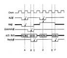
도1은 종래의 완전 병렬 방식의 버스 사이클을 도시한 도면이다. 도면의 상부에 도시된 클럭 신호는 시스템 클럭 신호로서 마이크로프로세서와 메모리 모듈간의 동기를 맞추기 위해서 공급하는 신호이다. 다음 신호인 ALE# 신호는 어드레스 래치 인에이블 신호로서 마이크로프로세서가 외부 모듈로 하여금 버스에 실린 어드레스 값을 래치하도록 명령하는 신호이다. RW# 신호는 마이크로프로세서의 입장에서 현재의 신호가 리드(Read) 인지 라이트(Write) 인가를 나타낸다. 이 신호가 0 일 때는 라이트 신호이며, 1 일 때는 리드 신호이다. DataValid# 신호는 마이크로프로세서가 버스에 의미있는 데이터를 실었음을 나타내는 신호이다. 이 신호는 0 일 때 인에이블된다. 즉, 0 일 때 마이크로프로세서 버스에 데이터가 실렸음을 나타낸다. Ready# 신호는 외부 메모리 모듈이 발생하는 신호로서 라이트 시에는 데이터를 잘 받았다는 것을 나타내고, 리드시에는 데이터를 버스에 실어 놓았다는 것을 의미한다. A/D_BUS 에는 데이터와 어드레스 신호가 실린다. 여기서 # 기호가 붙은 모든 신호는 0 일 때 인에이블임을 의미한다. 그리고 굵은 실선은 의미없는 값을 나타낸다.1 is a diagram illustrating a conventional fully parallel bus cycle. The clock signal shown in the upper part of the figure is a system clock signal which is supplied to synchronize the microprocessor and the memory module. The next signal, the ALE # signal, is an address latch enable signal that instructs the microprocessor to latch an address value loaded on the bus. The RW # signal indicates whether the current signal is Read or Write from the microprocessor's point of view. When this signal is 0, it is a write signal, and when it is 1, it is a read signal. The DataValid # signal indicates that the microprocessor has loaded meaningful data on the bus. This signal is enabled when zero. In other words, when 0, data is loaded on the microprocessor bus. The Ready # signal is generated by the external memory module, which indicates that data was well received at the time of writing, and that data was put on the bus at the time of read. A / D_BUS carries data and address signals. All signals with a # sign are enabled when they are zero. And the thick solid line represents a meaningless value.
도1은 완전 병렬 버스 방식에서 라이트 사이클과 리드 사이클에서 마이크로프로세서와 외부 메모리가 데이터를 주고 받는 과정을 도시한다. 먼저 라이트 사이클을 보면 다음과 같다. 즉, 마이크로프로세서는 라이트를 위해서 즉, 외부 메모리에 데이터를 기록해 넣기 위해서 RW# 신호를 0 로 만들게 된다. 동시에 A/D 버스에 어드레스 값을 실은 후 ALE#를 0 로 떨어뜨림으로서 외부 메모리가 버스에 실린 어드레스 값을 래치하여 데이터를 기록할 주소를 인식하게 된다. 이와같이 하여 라이트 사이클을 시작한다. 외부 메모리 모듈은 시스템 클럭 신호가 포지티브 에지일 때 ALE# 값을 샘플링하고 있다가 ALE# 가 0 이면 버스에 실린 어드레스 값을 래치한다. 그리고 WR# 신호를 참조하여 마이크로프로세서가 리드를 원하는지 라이트를 원하는지를 체크하게 된다. 이 순간이 도면에 A로 표시되어 있다.1 illustrates a process in which a microprocessor and an external memory exchange data in write cycles and read cycles in a fully parallel bus scheme. First, the light cycle is as follows. That is, the microprocessor will zero the RW # signal for writing, i.e. writing data to external memory. At the same time, by loading the address value on the A / D bus and dropping ALE # to 0, the external memory latches the address value loaded on the bus to recognize the address to which data is to be written. In this way, the light cycle starts. The external memory module samples the ALE # value when the system clock signal is on the positive edge and latches the address value on the bus when ALE # is zero. The WR # signal is then used to check whether the microprocessor wants to read or write. This moment is indicated by A in the figure.
마이크로프로세서는 한 클럭 주기동안 버스에 어드레스를 싣고 있다가 버스에 데이터를 싣고 DataValid# 신호를 0 로 만든다. 외부 모듈은 다음 클럭의 포지티브 에지에서 데이터가 Valid(유효)한지를 체크하고 데이터를 저장한 후 Ready# 신호를 0 로 만든다. 이 순간이 B 이다. 마이크로프로세서는 클럭의 네거티브 에지에서 ready# 신호를 샘플링하다가 0 가 되면 라이트 사이클을 끝낸다. 이 순간이 C 이다.The microprocessor puts an address on the bus for one clock period, then loads data on the bus and zeroes the DataValid # signal. The external module checks if the data is valid on the positive edge of the next clock, stores the data, and zeroes the Ready # signal. This moment is B. The microprocessor samples the ready # signal on the negative edge of the clock and ends the write cycle when it reaches zero. This moment is C.
리드 사이클일 때에는 마이크로프로세서가 A/D BUS에 어드레스 값을 싣고, RW#의 값을 1 로 만든 다음, ALE#을 0 로 떨어뜨려서 리드 사이클을 시작하게 된다. 외부 메모리 모듈은 클럭의 포지티브 에지에서 ALE#을 샘플링하고 있다가 0 이면, A/D BUS의 어드레스 값을 래치하고 RW# 값이 1 이므로 리드 사이클임을 확인하게 된다. 이때 외부 모듈은 데이터를 준비하게 된다. 이 순간이 D 시점이다. 메모리 모듈에서 데이터 준비가 완료되면, 이 값을 A/D BUS에 싣고 Ready# 신호를 0 으로 만든다. 이 순간이 E 이다. 마이크로프로세서는 클럭의 네거티브 에지에서 Ready#를 샘플링하고 있다가 0 이되면 A/D BUS에 실린 데이터 값을 읽어가고 리드 사이클을 마치게 된다. 이 순간이 F 이다.During the read cycle, the microprocessor loads the address on the A / D BUS, sets the value of RW # to 1, and drops the ALE # to 0 to start the read cycle. The external memory module samples ALE # on the positive edge of the clock and if it is 0, latches the address value of the A / D BUS and confirms that it is a read cycle because the RW # value is 1. At this time, the external module prepares data. This moment is the D point. When data is ready in the memory module, this value is loaded on the A / D BUS and the Ready # signal is zero. This moment is E. The microprocessor samples Ready # on the negative edge of the clock, and when it reaches zero, it reads the data value on the A / D BUS and finishes the read cycle. This moment is F.
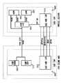
이와 같은 종래의 완전 병렬 방식의 하드웨어 구조는 개략적으로 도2와 같은 구조이다. 하드웨어 구조의 세부적인 사항은 본 발명과 관련이 없으므로 자세한 내용은 생략하고 개략적인 구성을 도시한다. 마이크로프로세서와 외부 모듈은 각각 버스 사이클을 제어하기 위하여 내부에 버스 장치(210)를 가지고 있다. 이들 버스들은 여러 가지 제어 회로와 레지스터들을 가지고 있다. 버스 장치의 세부적인 구성은 본 발명과 관계가 없으므로 간단히 모든 제어 회로들은 버스 제어 장치로 표현하였고 대표적인 레지스터들을 도면에 도시하였다. 버스 제어 장치는 버스 장치를 구성하는 모든 하드웨어에 대한 제어 신호를 생성하고 버스 사이클을 도시한 도1의 버스 사이클이 정확하게 유지되도록 관리한다. 도2는 어드레스 버스와 데이터 버스를 공유하는 경우를 도시한 것으로서 마이크로프로세서의 버스 장치에 2 x 1 MUX(250)가 필요하다. 이러한 2 x 1 MUX는 적절한 시점에 A/D BUS에 어드레스 또는 데이터를 싣기 위해서 필요한 장치이다. MAR은 메모리 어드레스 레지스터로서 데이터의 주소를 임시로 저장하는 레지스터이다. MDR은 메모리 데이터 레지스터로서 메모리 데이터를 임시로 저장하는 레지스터이다. 외부 메모리 장치에도 어드레스 래치와 데이터 래치가 있어서 메모리 어드레스와 데이터를 임시로 저장한다. 이와 같이 구성된 하드웨어 구성에서 데이터를 처리하는 과정을 보면 다음과 같다.The hardware structure of the conventional fully parallel method is a structure as schematically shown in FIG. Details of the hardware structure are not related to the present invention, so the detailed description is omitted and a schematic configuration is shown. The microprocessor and external module each have a
도3은 본 발명의 직병렬 방식의 버스 사이클을 도시한 도면이다. 도면에 도시된 신호들의 동작은 종래에서와 동일하다. 도3에서는 설명의 편의를 위해서 마이크로프로세서에서 한번에 처리할 수 있는 데이터의 크기를 16 비트라고 가정한다. 즉, 전술된 n 값을 16 이라고 가정한다. 그리고 외부 패키지로 빼내어 사용하는 핀의 수를 4라고 가정한다. 즉, m 값을 4 라고 가정한다. 또한 어드레스 버스의 비트의 크기를 4 라고 가정한다. 이처럼 16 비트의 데이터를 전송하기 위해서는 n/m 즉, 4 번으로 나누어서 4 비트씩 전송해야 한다. 이때 도3은 버스 사이클을 적절히 나타내고 있다. 모든 신호 동작은 도1과 같으며, 데이터 전송 부분이 4 사이클로 늘어났음을 볼 수 있다. 매 시스템 클럭의 한 클럭마다 데이터가 4 비트씩 전송되게 된다. 이와 같은 버스 사이클을 구현하기 위해서는 마이크로프로세서와 외부 메모리 모듈의 하드웨어 구성이 종래와는 약간 달라져야 한다.3 is a diagram illustrating a bus cycle of a serial and parallel type of the present invention. The operation of the signals shown in the figure is the same as in the prior art. In FIG. 3, for convenience of description, it is assumed that the size of data that can be processed at one time by the microprocessor is 16 bits. In other words, it is assumed that the above-described n value is 16. And suppose that the number of pins taken out of the external package and used is 4. That is, assume that m is 4. Also assume that the bit size of the address bus is four. In order to transmit 16 bits of data like this, n / m, that is, divided into 4 times and transmitted by 4 bits. 3 shows the bus cycle as appropriate. All signal operations are the same as in FIG. 1, and it can be seen that the data transmission portion is increased by four cycles. Data is transmitted four bits per clock of each system clock. To implement such a bus cycle, the hardware configuration of the microprocessor and the external memory module must be slightly different from the conventional one.
도4는 본 발명의 직병렬 버스 구조의 마이크로프로세서와 메모리 모듈의 하드웨어 구성을 도시한 개략적인 도면이다. 본 발명의 하드웨어 구성과 종래의 구성(도2)과의 차이점은, 종래의 구성에서 MDR과 DATA Latch가 단순한 레지스터인데 반해서 본 발명의 구성에서는 더 복잡한 구조의 MDR 장치(410)와 DATA Latch 장치(420)로 바뀌었다는 것이다. 물론 각각의 버스 제어 장치의 구조도 상당히 바뀌어야 하지만 본 발명의 사상이 반영되도록 버스 제어 장치를 바꾸는 방법을 일일이 열거할 수 없으므로 생략하도록 한다. 그러나 도3에 도시된 것과 같은 버스 사이클이 이루어지도록 버스 제어 장치를 바꾸어주어야 한다.4 is a schematic diagram showing a hardware configuration of a microprocessor and a memory module of the serial and parallel bus structure of the present invention. The difference between the hardware configuration of the present invention and the conventional configuration (FIG. 2) is that MDR and DATA Latch are simple registers in the conventional configuration, whereas in the configuration of the present invention, the
본 발명의 핵심인 MDR 장치와 데이터 래치 장치에 대해서 상세히 설명한다. 도5는 본 발명의 직병렬 버스 구조의 하드웨어 중 MDR 장치를 도시한 도면이다. 역시 설명을 간단히 하기 위해서 본 실시예도 도3의 경우와 마찬가지로 한번에 전송되는 데이터의 크기는 16 비트로 하고, 4비트씩 4번에 걸쳐서 전송하는 경우를 예시한다. 먼저 본 고안의 MDR은 완전 병렬 방식의 MDR과 같은 역할을 한다. 다만 본 고안의 직병렬 방식에서는 MDR의 데이터를 한번에 버스에 실어올 수 없으므로 m 개의 쉬프트 레지스터가 필요하다. 각 쉬프트 레지스터의 비트 수는 n/m 으로 결정된다.The MDR device and the data latch device, which are the core of the present invention, will be described in detail. FIG. 5 is a diagram illustrating an MDR device among hardware of a serial / parallel bus structure according to the present invention. For simplicity, the present embodiment also exemplifies a case in which the size of data to be transmitted at once is 16 bits and four times of 4 bits are transmitted. First, the MDR of the present invention acts like an MDR in a completely parallel manner. However, in the serial / parallel method of the present invention, since MDR data cannot be loaded on the bus at once, m shift registers are required. The number of bits in each shift register is determined by n / m.
MDR의 데이터들은 m 으로 나누어져서 각각의 쉬프트 레지스터들로 들어간다. 도5에서 MDR의 최하위 4 비트는 4개의 MDSR(메모리 데이터 쉬프트 레지스터)의 최하위 비트 즉, 0 번째 비트로 들어간다. 그리고 다음의 4 비트는 4개의 MDSR의 1번째 비트에 들어간다. 이런 식으로 MDR의 내용물을 MDSR에 저장시킨다. 그후 MDSR의 쉬프트 기능을 이용하여 MDSR 각각의 0 번째 비트부터 순서대로 데이터를 전송하면 도3과 같이 시스템 클럭 신호의 매 클럭 주기마다 m 비트씩을 전송할 수 있다.The data of the MDR is divided by m into each shift register. In FIG. 5, the least significant 4 bits of the MDR go into the least significant bit of the four MDSRs (memory data shift registers), that is, the 0th bit. The next four bits are in the first bit of four MDSRs. In this way, the contents of the MDR are stored in the MDSR. Thereafter, when data is transmitted in order from the 0 th bit of each MDSR using the shift function of the MDSR, m bits may be transmitted in every clock period of the system clock signal as shown in FIG. 3.
데이터를 읽을 때는 데이터를 기록할 때와 반대로 메모리 모듈에서 온 데이터 신호를 A/D BUS에 실어서는 MDSR에서 순차적으로 데이터를 입력 받은 후에 다시 MSR로 로딩하게 된다. MDR과 MDSR은 하드 와이어드(hard wired)되어 있기 때문에 별도의 하드웨어를 필요로 하지 않는다.When reading data, the data signal from the memory module is loaded on the A / D BUS as opposed to writing the data, and the data is sequentially loaded in the MDSR and then loaded into the MSR. MDR and MDSR are hard wired and do not require separate hardware.
도6은 본 발명의 직병렬 버스 구조의 하드웨어 중 데이터 래치 장치를 도시한 도면이다. 이러한 데이터 래치 장치는 외부 메모리 모듈에서 필요한 장치로서 그 동작은 도5의 MDR 장치에서와 같다. 즉, 16 비트의 데이터를 4 비트씩 4번에 나누어서 전송 및 수신하기 위해서 4개의 데이터 쉬프트 레지스터(DSR0 - DSR3)를 가지고 있다. 이러한 쉬프트 레지스터들은 마이크로프로세서와 데이터를 주고 받을 때 메모리 데이터 쉬프트 레지스터(MDSR0 - MDSR3)와 직접 데이터를 주고 받게 된다.FIG. 6 is a diagram illustrating a data latch device in hardware of a serial / parallel bus structure according to the present invention. The data latch device is a device required by an external memory module, and its operation is the same as that of the MDR device of FIG. That is, it has four data shift registers DSR0-DSR3 for transmitting and receiving 16-bit data divided into four bits at four times. These shift registers exchange data directly with the memory data shift registers (MDSR0-MDSR3) when exchanging data with the microprocessor.
이와 같이 본 발명을 실시하므로 다음과 같은 효과를 얻을 수 있다. 즉, 마이크로프로세서가 고성능화 되어 감에 따라서 한번에 처리하는 데이터의 숫자가 점차 늘어가는데 반해 패키지의 핀수를 늘려가는 데는 한계가 있으므로 이를 극복하기 위해서 데이터를 종래의 완전 병렬 방식으로 전송하던 것을 직병렬 방식으로 전송하므로 제한된 패키지 핀으로도 확장된 데이터를 처리하는 것이 가능해 졌다. 또한 직렬 방식을 적용할 때 발생할 수 있는 마이크로프로세서의 성능 저하를 최소화 시킬 수 있게된다.Thus, since the present invention is implemented, the following effects can be obtained. In other words, as the number of data processed at a time increases as the microprocessor becomes higher, there is a limit in increasing the number of pins of the package. The transfer makes it possible to handle extended data even with limited package pins. In addition, the performance degradation of the microprocessor that can occur when the serial method is applied can be minimized.
Claims (6)
Translated fromKoreanPriority Applications (3)
| Application Number | Priority Date | Filing Date | Title |
|---|---|---|---|
| KR1019970077873AKR100265362B1 (en) | 1997-12-30 | 1997-12-30 | Data Transmission / Reception Method of Microprocessor Using Serial Parallel Method |
| JP10377361AJP2000057084A (en) | 1997-12-30 | 1998-12-29 | Data transmitting/receiving method for microprocessor |
| US09/223,386US6339800B1 (en) | 1997-12-30 | 1998-12-30 | Method for transmitting data between a microprocessor and an external memory module by using combined serial/parallel process |
Applications Claiming Priority (1)
| Application Number | Priority Date | Filing Date | Title |
|---|---|---|---|
| KR1019970077873AKR100265362B1 (en) | 1997-12-30 | 1997-12-30 | Data Transmission / Reception Method of Microprocessor Using Serial Parallel Method |
Publications (2)
| Publication Number | Publication Date |
|---|---|
| KR19990057794A KR19990057794A (en) | 1999-07-15 |
| KR100265362B1true KR100265362B1 (en) | 2000-09-15 |
Family
ID=19529688
Family Applications (1)
| Application Number | Title | Priority Date | Filing Date |
|---|---|---|---|
| KR1019970077873AExpired - Fee RelatedKR100265362B1 (en) | 1997-12-30 | 1997-12-30 | Data Transmission / Reception Method of Microprocessor Using Serial Parallel Method |
Country Status (3)
| Country | Link |
|---|---|
| US (1) | US6339800B1 (en) |
| JP (1) | JP2000057084A (en) |
| KR (1) | KR100265362B1 (en) |
Cited By (1)
| Publication number | Priority date | Publication date | Assignee | Title |
|---|---|---|---|---|
| KR100394065B1 (en)* | 2000-09-16 | 2003-08-09 | 주식회사 하이닉스반도체 | Circuit for selecting serial and parallel program mode of eprom equipped with microcontroller |
Families Citing this family (3)
| Publication number | Priority date | Publication date | Assignee | Title |
|---|---|---|---|---|
| KR100385231B1 (en)* | 2001-04-17 | 2003-05-27 | 삼성전자주식회사 | Bus system |
| JP4489454B2 (en)* | 2004-02-16 | 2010-06-23 | 富士通マイクロエレクトロニクス株式会社 | Semiconductor integrated circuit |
| US8700818B2 (en)* | 2006-09-29 | 2014-04-15 | Mosaid Technologies Incorporated | Packet based ID generation for serially interconnected devices |
Family Cites Families (23)
| Publication number | Priority date | Publication date | Assignee | Title |
|---|---|---|---|---|
| JPS62212739A (en) | 1986-03-13 | 1987-09-18 | Nec Corp | Large scale integrated circuit |
| JPS6362045A (en) | 1986-09-03 | 1988-03-18 | Nec Corp | Package control system |
| US4760517A (en)* | 1986-10-17 | 1988-07-26 | Integrated Device Technology, Inc. | Thirty-two bit, bit slice processor |
| US5084814A (en) | 1987-10-30 | 1992-01-28 | Motorola, Inc. | Data processor with development support features |
| US4888731A (en)* | 1988-05-11 | 1989-12-19 | Advanced Micro Devices, Inc. | Content addressable memory array system with multiplexed status and command information |
| US4901268A (en)* | 1988-08-19 | 1990-02-13 | General Electric Company | Multiple function data processor |
| US5430859A (en) | 1991-07-26 | 1995-07-04 | Sundisk Corporation | Solid state memory system including plural memory chips and a serialized bus |
| JPH0589041A (en) | 1991-09-30 | 1993-04-09 | Casio Comput Co Ltd | Data processor |
| JP3369227B2 (en)* | 1992-11-09 | 2003-01-20 | 株式会社東芝 | Processor |
| JPH06174802A (en) | 1992-12-03 | 1994-06-24 | Kawasaki Steel Corp | Cpu mounted integrated circuit and debugger |
| FR2704783B1 (en) | 1993-05-06 | 1995-07-28 | Clecim Sa | METHOD FOR METAL SPINNING AND IMPROVED SPINNING PRESS. |
| US5634069A (en) | 1994-01-28 | 1997-05-27 | Vlsi Technology, Inc. | Encoding assertion and de-assertion of interrupt requests and DMA requests in a serial bus I/O system |
| US5475854A (en) | 1994-01-28 | 1995-12-12 | Vlsi Technology, Inc. | Serial bus I/O system and method for serializing interrupt requests and DMA requests in a computer system |
| US5664213A (en) | 1994-01-28 | 1997-09-02 | Vlsi Technology, Inc. | Input/output (I/O) holdoff mechanism for use in a system where I/O device inputs are fed through a latency introducing bus |
| US5404460A (en) | 1994-01-28 | 1995-04-04 | Vlsi Technology, Inc. | Method for configuring multiple identical serial I/O devices to unique addresses through a serial bus |
| US5611055A (en) | 1994-09-27 | 1997-03-11 | Novalink Technologies | Method and apparatus for implementing a PCMCIA auxiliary port connector for selectively communicating with peripheral devices |
| JPH08153064A (en) | 1994-11-30 | 1996-06-11 | Sanyo Electric Co Ltd | Bus width extension circuit and data transfer system |
| US5606710A (en) | 1994-12-20 | 1997-02-25 | National Semiconductor Corporation | Multiple chip package processor having feed through paths on one die |
| US5655138A (en) | 1995-04-11 | 1997-08-05 | Elonex I. P. Holdings | Apparatus and method for peripheral device control with integrated data compression |
| US5561055A (en) | 1995-05-05 | 1996-10-01 | Bcm Developpement Inc. | Bacterial mass production of taxanes with Erwinia |
| US5809233A (en)* | 1995-12-05 | 1998-09-15 | Lucent Technologies Inc. | Method of mapping from ATMARP to NHRP |
| JPH09305535A (en) | 1996-05-15 | 1997-11-28 | Nec Corp | Asynchronous multiplexing system for control system serial bus |
| US5898898A (en)* | 1996-05-31 | 1999-04-27 | Kleck; James | Collating bits from a byte source |
- 1997
- 1997-12-30KRKR1019970077873Apatent/KR100265362B1/ennot_activeExpired - Fee Related
- 1998
- 1998-12-29JPJP10377361Apatent/JP2000057084A/enactivePending
- 1998-12-30USUS09/223,386patent/US6339800B1/ennot_activeExpired - Lifetime
Cited By (1)
| Publication number | Priority date | Publication date | Assignee | Title |
|---|---|---|---|---|
| KR100394065B1 (en)* | 2000-09-16 | 2003-08-09 | 주식회사 하이닉스반도체 | Circuit for selecting serial and parallel program mode of eprom equipped with microcontroller |
Also Published As
| Publication number | Publication date |
|---|---|
| US6339800B1 (en) | 2002-01-15 |
| KR19990057794A (en) | 1999-07-15 |
| JP2000057084A (en) | 2000-02-25 |
Similar Documents
| Publication | Publication Date | Title |
|---|---|---|
| US4181934A (en) | Microprocessor architecture with integrated interrupts and cycle steals prioritized channel | |
| US6275902B1 (en) | Data processor with variable types of cache memories and a controller for selecting a cache memory to be access | |
| KR950008226B1 (en) | Bus master with burst transfer mode | |
| US5131083A (en) | Method of transferring burst data in a microprocessor | |
| US5146582A (en) | Data processing system with means to convert burst operations into memory pipelined operations | |
| KR100341948B1 (en) | Data processor with controlled burst memory access function and its method | |
| US4378589A (en) | Undirectional looped bus microcomputer architecture | |
| US8046568B2 (en) | Microprocessor with integrated high speed memory | |
| US6014721A (en) | Method and system for transferring data between buses having differing ordering policies | |
| US4339793A (en) | Function integrated, shared ALU processor apparatus and method | |
| US8732377B2 (en) | Interconnection apparatus and controlling method therefor | |
| WO2005071556A1 (en) | A two channel bus structure to support address information, data, and transfer qualifiers | |
| US6898659B2 (en) | Interface device having variable data transfer mode and operation method thereof | |
| KR100265362B1 (en) | Data Transmission / Reception Method of Microprocessor Using Serial Parallel Method | |
| JPH04362759A (en) | Central processing unit | |
| JPS63116236A (en) | information processing equipment | |
| KR19990023208A (en) | Dual Processor Mode Memory Controller | |
| US6877046B2 (en) | Method and apparatus for memory with embedded processor | |
| WO1996038773A2 (en) | Integrated primary bus and secondary bus controller with reduced pin count | |
| US20050027906A1 (en) | System and method for adaptive buffer allocation in a memory device interface | |
| US20020188771A1 (en) | Direct memory access controller for carrying out data transfer by determining whether or not burst access can be utilized in an external bus and access control method thereof | |
| US5951668A (en) | Method and system for transferring data between buses having differing ordering policies | |
| US5793991A (en) | Method of equalizing loads on a computer bus | |
| US5901299A (en) | Method and apparatus for transferring data between buses having differing ordering policies | |
| CA1103370A (en) | Microprocessor architecture with integrated interrupts and cycle steals prioritized channel |
Legal Events
| Date | Code | Title | Description |
|---|---|---|---|
| A201 | Request for examination | ||
| PA0109 | Patent application | St.27 status event code:A-0-1-A10-A12-nap-PA0109 | |
| PA0201 | Request for examination | St.27 status event code:A-1-2-D10-D11-exm-PA0201 | |
| R17-X000 | Change to representative recorded | St.27 status event code:A-3-3-R10-R17-oth-X000 | |
| PG1501 | Laying open of application | St.27 status event code:A-1-1-Q10-Q12-nap-PG1501 | |
| E701 | Decision to grant or registration of patent right | ||
| PE0701 | Decision of registration | St.27 status event code:A-1-2-D10-D22-exm-PE0701 | |
| GRNT | Written decision to grant | ||
| PR0701 | Registration of establishment | St.27 status event code:A-2-4-F10-F11-exm-PR0701 | |
| PR1002 | Payment of registration fee | St.27 status event code:A-2-2-U10-U11-oth-PR1002 Fee payment year number:1 | |
| PG1601 | Publication of registration | St.27 status event code:A-4-4-Q10-Q13-nap-PG1601 | |
| PN2301 | Change of applicant | St.27 status event code:A-5-5-R10-R13-asn-PN2301 St.27 status event code:A-5-5-R10-R11-asn-PN2301 | |
| PN2301 | Change of applicant | St.27 status event code:A-5-5-R10-R13-asn-PN2301 St.27 status event code:A-5-5-R10-R11-asn-PN2301 | |
| R17-X000 | Change to representative recorded | St.27 status event code:A-5-5-R10-R17-oth-X000 | |
| PR1001 | Payment of annual fee | St.27 status event code:A-4-4-U10-U11-oth-PR1001 Fee payment year number:4 | |
| PR1001 | Payment of annual fee | St.27 status event code:A-4-4-U10-U11-oth-PR1001 Fee payment year number:5 | |
| PN2301 | Change of applicant | St.27 status event code:A-5-5-R10-R11-asn-PN2301 | |
| PN2301 | Change of applicant | St.27 status event code:A-5-5-R10-R14-asn-PN2301 | |
| S20-X000 | Security interest recorded | St.27 status event code:A-4-4-S10-S20-lic-X000 | |
| PR1001 | Payment of annual fee | St.27 status event code:A-4-4-U10-U11-oth-PR1001 Fee payment year number:6 | |
| PR1001 | Payment of annual fee | St.27 status event code:A-4-4-U10-U11-oth-PR1001 Fee payment year number:7 | |
| PR1001 | Payment of annual fee | St.27 status event code:A-4-4-U10-U11-oth-PR1001 Fee payment year number:8 | |
| PR1001 | Payment of annual fee | St.27 status event code:A-4-4-U10-U11-oth-PR1001 Fee payment year number:9 | |
| PR1001 | Payment of annual fee | St.27 status event code:A-4-4-U10-U11-oth-PR1001 Fee payment year number:10 | |
| PR1001 | Payment of annual fee | St.27 status event code:A-4-4-U10-U11-oth-PR1001 Fee payment year number:11 | |
| S22-X000 | Recordation of security interest cancelled | St.27 status event code:A-4-4-S10-S22-lic-X000 | |
| PR1001 | Payment of annual fee | St.27 status event code:A-4-4-U10-U11-oth-PR1001 Fee payment year number:12 | |
| PN2301 | Change of applicant | St.27 status event code:A-5-5-R10-R13-asn-PN2301 St.27 status event code:A-5-5-R10-R11-asn-PN2301 | |
| PR1001 | Payment of annual fee | St.27 status event code:A-4-4-U10-U11-oth-PR1001 Fee payment year number:13 | |
| PN2301 | Change of applicant | St.27 status event code:A-5-5-R10-R13-asn-PN2301 St.27 status event code:A-5-5-R10-R11-asn-PN2301 | |
| FPAY | Annual fee payment | Payment date:20130524 Year of fee payment:14 | |
| PR1001 | Payment of annual fee | St.27 status event code:A-4-4-U10-U11-oth-PR1001 Fee payment year number:14 | |
| FPAY | Annual fee payment | Payment date:20140519 Year of fee payment:15 | |
| PR1001 | Payment of annual fee | St.27 status event code:A-4-4-U10-U11-oth-PR1001 Fee payment year number:15 | |
| PN2301 | Change of applicant | St.27 status event code:A-5-5-R10-R13-asn-PN2301 St.27 status event code:A-5-5-R10-R11-asn-PN2301 | |
| FPAY | Annual fee payment | ||
| PR1001 | Payment of annual fee | St.27 status event code:A-4-4-U10-U11-oth-PR1001 Fee payment year number:16 | |
| FPAY | Annual fee payment | Payment date:20160518 Year of fee payment:17 | |
| PR1001 | Payment of annual fee | St.27 status event code:A-4-4-U10-U11-oth-PR1001 Fee payment year number:17 | |
| LAPS | Lapse due to unpaid annual fee | ||
| PC1903 | Unpaid annual fee | St.27 status event code:A-4-4-U10-U13-oth-PC1903 Not in force date:20170614 Payment event data comment text:Termination Category : DEFAULT_OF_REGISTRATION_FEE | |
| PC1903 | Unpaid annual fee | St.27 status event code:N-4-6-H10-H13-oth-PC1903 Ip right cessation event data comment text:Termination Category : DEFAULT_OF_REGISTRATION_FEE Not in force date:20170614 |