KR100263891B1 - Movable mirror - Google Patents
Movable mirrorDownload PDFInfo
- Publication number
- KR100263891B1 KR100263891B1KR1019970082105AKR19970082105AKR100263891B1KR 100263891 B1KR100263891 B1KR 100263891B1KR 1019970082105 AKR1019970082105 AKR 1019970082105AKR 19970082105 AKR19970082105 AKR 19970082105AKR 100263891 B1KR100263891 B1KR 100263891B1
- Authority
- KR
- South Korea
- Prior art keywords
- electrode
- mirror
- reflective mirror
- support
- support piece
- Prior art date
- Legal status (The legal status is an assumption and is not a legal conclusion. Google has not performed a legal analysis and makes no representation as to the accuracy of the status listed.)
- Expired - Fee Related
Links
Images


Classifications
- G—PHYSICS
- G02—OPTICS
- G02B—OPTICAL ELEMENTS, SYSTEMS OR APPARATUS
- G02B26/00—Optical devices or arrangements for the control of light using movable or deformable optical elements
- G02B26/08—Optical devices or arrangements for the control of light using movable or deformable optical elements for controlling the direction of light
- G02B26/0816—Optical devices or arrangements for the control of light using movable or deformable optical elements for controlling the direction of light by means of one or more reflecting elements
- G02B26/0833—Optical devices or arrangements for the control of light using movable or deformable optical elements for controlling the direction of light by means of one or more reflecting elements the reflecting element being a micromechanical device, e.g. a MEMS mirror, DMD
- G02B26/0841—Optical devices or arrangements for the control of light using movable or deformable optical elements for controlling the direction of light by means of one or more reflecting elements the reflecting element being a micromechanical device, e.g. a MEMS mirror, DMD the reflecting element being moved or deformed by electrostatic means
- H—ELECTRICITY
- H04—ELECTRIC COMMUNICATION TECHNIQUE
- H04N—PICTORIAL COMMUNICATION, e.g. TELEVISION
- H04N5/00—Details of television systems
- H04N5/74—Projection arrangements for image reproduction, e.g. using eidophor
Landscapes
- Physics & Mathematics (AREA)
- General Physics & Mathematics (AREA)
- Optics & Photonics (AREA)
- Engineering & Computer Science (AREA)
- Multimedia (AREA)
- Signal Processing (AREA)
- Mechanical Light Control Or Optical Switches (AREA)
- Mounting And Adjusting Of Optical Elements (AREA)
Abstract
Translated fromKoreanDescription
Translated fromKorean본 발명은 입사광의 진행경로를 변환시킬 수 있도록 된 가동미러장치에 관한 것으로서, 상세하게는 낮은 구동전압으로 광 경로 변환 각도의 조절이 용이하도록 그 구조가 개선된 가동미러장치에 관한 것이다.The present invention relates to a movable mirror device capable of converting a traveling path of incident light, and more particularly, to a movable mirror device having an improved structure to facilitate adjustment of an optical path conversion angle at a low driving voltage.
일반적으로 가동미러장치(DMD; Deformable Mirror Device)는 정전기력에 의해 회동 가능하도록 설치된 복수의 반사거울을 포함하여 입사되는 광을 소정 각도로 반사시킨다. 이 가동미러장치는 프로젝션 텔레비젼의 화상표시장치 및, 스캐너, 복사기, 팩시밀리 등의 광주사장치에 적용된다. 특히, 화상표시장치로 채용시 반사거울은 화소 수 만큼 이차원적으로 배열되며, 각각의 반사거울을 각 화소에 대한 영상신호에 따라 회동시킴으로써 광을 반사시켜 색깔과 밝기를 조절한다.In general, a deformable mirror device (DMD) includes a plurality of reflection mirrors installed to be rotatable by an electrostatic force to reflect incident light at a predetermined angle. This movable mirror apparatus is applied to an image display apparatus of a projection television and an optical scanning apparatus such as a scanner, a copier, a facsimile and the like. In particular, when employed as an image display device, the reflection mirrors are arranged two-dimensionally by the number of pixels, and the respective reflection mirrors are rotated according to the image signal for each pixel to reflect light to adjust color and brightness.
도 1은 종래의 가동미러장치를 보인 사시도이다. 도시된 바와 같이, 종래의 가동미러장치는 기판(1)과, 상기 기판(1)의 상면에 소정 간격 이격된 채로 돌출 형성된 한쌍의 포스트(3)와, 상기 기판(1) 상에 형성된 전극(5)과, 상기 포스트(3)에 의해 지지되며 상기 전극(5)과 마주하도록 배치된 반사거울(7)과, 상기 반사거울(7)의 양측 각각과 상기 포스트(3) 사이에 연결되어 상기 반사거울(7)을 지지하는 한쌍의 지지편(9)을 포함하여 구성된다.1 is a perspective view showing a conventional movable mirror device. As shown in the drawing, a conventional movable mirror device includes a
상기 지지편(9)은 도시된 바와 같이 비대칭(L1 ≠ L2) 구조로 어느한 지지편(9a)이 다른 한 지지편(9b)에 비하여 짧게 형성되며, 상기 반사거울(7)을 탄성적으로 지지할 수 있도록 강성을 가진다. 여기서, 상기 지지편(9)은 대칭 구조를 가질 수도 있다.As shown, the support piece 9 has an asymmetric (L1? L2) structure in which one
상기 전극(5)은 상기 반사거울(7)의 크기에 대응되는 크기를 가지며 상기 반사거울(7)과 마주하도록 상기 기판(1) 상에 설치된다. 따라서, 상기 전극(5)에 전위를 인가하면 상기 전극(5)과 반사거울(7) 사이의 전위차에 의해 정전인력이 작용하며, 상기 반사거울(7)이 상기 지지편(9)의 강성을 이기고 전극(5)쪽으로 내려가면서 그 기울기가 바뀌게 된다. 한편, 전극(5)과 반사거울(7) 사이에 전위차가 없어지면, 상기 지지편(9)의 강성에 의해 상기 반사거울(7)은 원래 상태로 복귀하여 수평상태를 유지한다.The
도 2는 비대칭 지지판 구조를 갖는 가동미러장치의 개략적인 정면도이다.2 is a schematic front view of a movable mirror having an asymmetric support plate structure.
도시된 바와 같이, 전극(5)과 반사거울(7) 사이에 전위차를 가하면, 지지편(9a)(9b)과 반사거울(7)의 연결된 부분 각각이 전극(5)쪽으로 힘
상기 힘
도면에서
한편, 도 3에 도시된 바와 같이, 두 지지편(9)이 대칭적으로 배치
따라서, 본 발명은 상기한 바와 같은 점을 감안하여 안출된 것으로서, 반사거울에 대한 전극의 위치를 조절하여 상대적으로 낮은 정전압 하에서 광경로 변환각을 크게할 수 있도록 된 가동미러장치를 제공하는데 그 목적이 있다.Accordingly, an object of the present invention is to provide a movable mirror device which is made in view of the above-described point, and is capable of increasing the optical path conversion angle under a relatively low constant voltage by adjusting the position of the electrode with respect to the reflective mirror. There is this.
도 1은 종래의 가동미러장치를 보인 개략적인 사시도.1 is a schematic perspective view showing a conventional movable mirror device.
도 2는 종래의 비대칭 지지판 구조를 갖는 가동미러장치의 개략적인 정면도.Figure 2 is a schematic front view of a movable mirror apparatus having a conventional asymmetric support plate structure.
도 3은 종래의 대칭 지지판 구조를 갖는 가동미러장치의 개략적인 정면도.3 is a schematic front view of a movable mirror apparatus having a conventional symmetrical support plate structure.
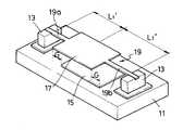
도 4는 본 발명의 실시예에 따른 가동미러장치를 보인 개략적인 사시도.Figure 4 is a schematic perspective view showing a movable mirror device according to an embodiment of the present invention.
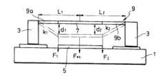
도 5는 본 발명의 실시예에 따른 비대칭 지지판 구조를 갖는 가동미러장치의 개략적인 정면도.5 is a schematic front view of a movable mirror apparatus having an asymmetric support plate structure according to an embodiment of the present invention.
도 6은 본 발명의 실시예에 따른 대칭 지지판 구조를 갖는 가동미러장치의 개략적인 정면도.Figure 6 is a schematic front view of a movable mirror having a symmetrical support plate structure according to an embodiment of the present invention.
* 도면의 주요 부분에 대한 부호의 설명 *Explanation of symbols on the main parts of the drawings
11...기판 13...포스트11
15...전극 17...반사거울15
19...지지편 19a...제1지지편19 ... Support 19a ... First Support
19b...제2지지편19b ... Secondary Support
상기한 목적을 달성하기 위하여, 본 발명은 기판과; 상기 기판의 상면에 소정 간격 이격된 채로 돌출 형성된 한쌍의 포스트와; 상기 기판 상에 형성된 전극과; 상기 포스트에 의해 지지되며 상기 전극에 대향하도록 배치된 반사거울과; 상기 반사거울의 양측 각각과 상기 포스트 사이에 연결되어 상기 반사거울을 지지하며 소정 강성을 갖는 한쌍의 제1 및 제2지지편;을 포함하여 상기 전극과 반사거울 사이의 정전인력에 의해 상기 반사거울의 기울기를 가변시킬 수 있도록 된 가동미러장치에 있어서, 상기 반사거울에 대해 상기 전극이 어느 한쪽으로 치우치게 배치되어, 상기 제1 및 제2 지지편 각각과 상기 반사거울 사이의 위치에서 상기 전극쪽으로 작용하는 힘의 세기가 서로 다르도록 된 것을 특징으로 한다.In order to achieve the above object, the present invention is a substrate; A pair of posts protruding from the upper surface of the substrate at predetermined intervals; An electrode formed on the substrate; A reflection mirror supported by the post and disposed to face the electrode; A pair of first and second support pieces connected between each of both sides of the reflective mirror and the post to support the reflective mirror and having a predetermined rigidity, the reflective mirror including an electrostatic force between the electrode and the reflective mirror. A movable mirror device adapted to vary the inclination of the mirror, wherein the electrode is disposed to be biased with respect to the reflective mirror, and acts toward the electrode at a position between each of the first and second support pieces and the reflective mirror. It is characterized in that the strength of the power is different from each other.
이하, 첨부된 도면을 참조하여 본 발명의 바람직한 실시예들을 상세히 설명한다.Hereinafter, exemplary embodiments of the present invention will be described in detail with reference to the accompanying drawings.
도 4는 본 발명의 실시예에 따른 가동미러장치를 보인 개략적인 사시도이다. 도시된 바와 같이, 가동미러장치는 기판(11)과, 이 기판(11)의 상면에 소정 간격 이격된 채로 돌출 형성된 한쌍의 포스트(13)와, 상기 기판(11) 상에 형성된 전극(15)과, 상기 포스트(13)에 의해 지지되며 상기 전극(15)에 대향하도록 배치된 반사거울(17)과, 상기 반사거울(17)을 지지하며 소정 강성을 갖는 지지편(9)을 포함하여 구성된다.Figure 4 is a schematic perspective view showing a movable mirror device according to an embodiment of the present invention. As shown in the drawing, the movable mirror device includes a
상기 지지편(9)은 상기 반사거울(17)의 양측에 각각과 상기 반사거울(17)의 양측 각각과 상기 포스트(13) 사이에 연결되어 상기 반사거울(17)을 지지할 수 있도록 제1지지편(19a)과 제2지지편(19b)으로 구성된다. 여기서, 상기 제1 및 제2지지편(19a)(19b)은 비대칭(
상기 전극(15)은 상기 반사거울(17)의 크기에 대응되는 크기를 가지며 상기 반사거울(17)에 대해 어느 한쪽으로 소정 간격(G) 만큼 치우치게 배치된다. 따라서, 상기 제1 및 제2지지편(19a)(19b) 각각과 상기 반사거울(17) 사이의 위치에서 상기 전극(15)쪽으로 작용하는 힘의 세기가 서로 다르도록 된 것에 특징이 있다. 여기서, 상기 전극(15)에 전위를 인가하면 상기 전극(15)과 반사거울(17) 사이의 전위차에 의해 정전인력이 작용하며, 상기 반사거울(17)이 상기 지지편(9)의 강성을 이기고 전극(15)쪽으로 내려가면서 그 기울기가 바뀌게 된다. 한편, 전극(15)과 반사거울(17) 사이에 전위차가 없어지면, 상기 지지편(9)의 강성에 의해 상기 반사거울(17)은 원래 상태로 복귀하여 수평상태를 유지한다.The
이하, 도 5 및 도 6을 참조하여 본 발명의 실시예에 따른 동작을 설명한다.Hereinafter, an operation according to an embodiment of the present invention will be described with reference to FIGS. 5 and 6.
도 5는 비대칭 지지판 구조를 갖는 가동미러장치의 개략적인 정면도이다. 도시된 바와 같이, 제1지지편(19a)에 걸리는 강성
전극(15)과 반사거울(17) 사이에 전위차를 가하면, 제1 및 제2지지편(19a)(19b)과 반사거울(17)의 연결된 부분 각각이 전극(15)쪽으로 힘
또한, 종래의 구성과는 달리 강성이 큰쪽
도 6은 대칭 지지판 구조를 갖는 가동미러장치의 개략적인 정면도이다. 도시된 바와 같이, 전극(15)이 도면의 우측 즉, 제2지지편(19b) 쪽으로 치우쳐 배치되어, 정전인력의 합력
도 4 내지 도 6에는 전극(15)이 반사거울(17)과 동일 크기를 가지고, 어느 한 쪽으로 소정 폭(G)만큼 이동 배치된 예를 들어 설명하였으나, 이는 예시적인 것에 불과하고, 상기한 정전인력의 합력
상기한 바와 같이, 구성된 본 발명에 따른 가동미러장치는 반사거울(17)에 대하여 전극(15)를 어느 한쪽으로 치우쳐 배치시킴에 의하여 반사거울(17)의 가동에 필요한 정전압을 낮출 수 있어서, 신뢰성 및 효율을 향상시킬 수 있다.As described above, the movable mirror apparatus according to the present invention can reduce the constant voltage required for the operation of the
또한, 반사거울(17)을 지지하는 제1 및 제2지지편(19a)(19b)을 대칭 구조로 한 경우에도 반사거울(17)의 기울어짐을 조절할 수 있는 이점이 있다.In addition, even when the first and
Claims (3)
Translated fromKoreanPriority Applications (6)
| Application Number | Priority Date | Filing Date | Title |
|---|---|---|---|
| KR1019970082105AKR100263891B1 (en) | 1997-12-31 | 1997-12-31 | Movable mirror |
| JP10180716AJP2941788B2 (en) | 1997-12-31 | 1998-06-26 | Movable mirror device |
| DE69808723TDE69808723T2 (en) | 1997-12-31 | 1998-07-03 | Arrangement with a deformable mirror |
| EP98305313AEP0927903B1 (en) | 1997-12-31 | 1998-07-03 | Deformable mirror device |
| CN98116719ACN1105933C (en) | 1997-12-31 | 1998-07-29 | Deformable mirror device |
| US09/128,441US5978128A (en) | 1997-12-31 | 1998-08-04 | Deformable mirror device |
Applications Claiming Priority (1)
| Application Number | Priority Date | Filing Date | Title |
|---|---|---|---|
| KR1019970082105AKR100263891B1 (en) | 1997-12-31 | 1997-12-31 | Movable mirror |
Publications (2)
| Publication Number | Publication Date |
|---|---|
| KR19990061815A KR19990061815A (en) | 1999-07-26 |
| KR100263891B1true KR100263891B1 (en) | 2000-08-16 |
Family
ID=19530751
Family Applications (1)
| Application Number | Title | Priority Date | Filing Date |
|---|---|---|---|
| KR1019970082105AExpired - Fee RelatedKR100263891B1 (en) | 1997-12-31 | 1997-12-31 | Movable mirror |
Country Status (6)
| Country | Link |
|---|---|
| US (1) | US5978128A (en) |
| EP (1) | EP0927903B1 (en) |
| JP (1) | JP2941788B2 (en) |
| KR (1) | KR100263891B1 (en) |
| CN (1) | CN1105933C (en) |
| DE (1) | DE69808723T2 (en) |
Families Citing this family (19)
| Publication number | Priority date | Publication date | Assignee | Title |
|---|---|---|---|---|
| US6178033B1 (en)* | 1999-03-28 | 2001-01-23 | Lucent Technologies | Micromechanical membrane tilt-mirror switch |
| KR100349941B1 (en)* | 2000-09-29 | 2002-08-24 | 삼성전자 주식회사 | Micro Actuator for optical switching and its manufacturing method |
| US6343178B1 (en) | 2000-11-07 | 2002-01-29 | Integrated Micromachines, Inc. | Micromachined voltage controlled optical attenuator |
| KR100464320B1 (en)* | 2002-11-19 | 2004-12-31 | 삼성전자주식회사 | Micromirror actuator and method for manufacturing the same |
| US6876484B2 (en)* | 2003-03-24 | 2005-04-05 | Lucent Technologies Inc. | Deformable segmented MEMS mirror |
| CN100368862C (en)* | 2004-01-16 | 2008-02-13 | 侯继东 | Adjustable reflection type device |
| CN100434962C (en)* | 2004-03-24 | 2008-11-19 | 德克萨斯仪器股份有限公司 | A torsional hinged mirror assembly with central spines and perimeter ridges to reduce flexing |
| FR2876460B1 (en)* | 2004-10-12 | 2007-05-18 | Centre Nat Rech Scient Cnrse | DEFORMABLE MIRROR |
| DE112005003758B4 (en)* | 2005-11-25 | 2011-12-08 | Fraunhofer-Gesellschaft zur Förderung der angewandten Forschung e.V. | Deflectible micromechanical element |
| JP5084841B2 (en)* | 2006-12-12 | 2012-11-28 | エヌエックスピー ビー ヴィ | MEMS device with controlled electrode off-state position |
| US8491121B2 (en)* | 2007-10-09 | 2013-07-23 | Elbit Systems Of America, Llc | Pupil scan apparatus |
| CN101515065B (en)* | 2009-02-26 | 2011-05-04 | 中国科学院光电技术研究所 | Electrostatic driving MEMS deformable mirror based on lever amplification principle |
| US8982480B2 (en) | 2009-12-29 | 2015-03-17 | Elbit Systems Of America, Llc | System and method for adjusting a projected image |
| US8905547B2 (en) | 2010-01-04 | 2014-12-09 | Elbit Systems Of America, Llc | System and method for efficiently delivering rays from a light source to create an image |
| CN103257448B (en)* | 2012-12-28 | 2016-06-08 | 清华大学 | Distorting lens |
| JP6507500B2 (en)* | 2014-07-01 | 2019-05-08 | セイコーエプソン株式会社 | Optical device and image display device |
| US11408788B2 (en)* | 2020-03-31 | 2022-08-09 | Toyota Research Institute, Inc. | Variable geometry and stiffness control for fluid filled sensor |
| CN114690400B (en)* | 2020-12-29 | 2023-05-02 | 极米科技股份有限公司 | Vibrating mirror driven by electrostatic force |
| CN115236850B (en)* | 2021-04-23 | 2024-03-15 | 成都极米科技股份有限公司 | Method for controlling vibrating mirror to achieve 2-time and 4-time pixel lifting and projector |
Family Cites Families (8)
| Publication number | Priority date | Publication date | Assignee | Title |
|---|---|---|---|---|
| US4317611A (en)* | 1980-05-19 | 1982-03-02 | International Business Machines Corporation | Optical ray deflection apparatus |
| US5526172A (en)* | 1993-07-27 | 1996-06-11 | Texas Instruments Incorporated | Microminiature, monolithic, variable electrical signal processor and apparatus including same |
| US5629790A (en)* | 1993-10-18 | 1997-05-13 | Neukermans; Armand P. | Micromachined torsional scanner |
| US5696619A (en)* | 1995-02-27 | 1997-12-09 | Texas Instruments Incorporated | Micromechanical device having an improved beam |
| US5629794A (en)* | 1995-05-31 | 1997-05-13 | Texas Instruments Incorporated | Spatial light modulator having an analog beam for steering light |
| US5739941A (en)* | 1995-07-20 | 1998-04-14 | Texas Instruments Incorporated | Non-linear hinge for micro-mechanical device |
| US5774604A (en)* | 1996-10-23 | 1998-06-30 | Texas Instruments Incorporated | Using an asymmetric element to create a 1XN optical switch |
| KR100259151B1 (en)* | 1997-08-26 | 2000-06-15 | 윤종용 | Optical path change actuator with asymmetric stiffness structure and driving method thereof |
- 1997
- 1997-12-31KRKR1019970082105Apatent/KR100263891B1/ennot_activeExpired - Fee Related
- 1998
- 1998-06-26JPJP10180716Apatent/JP2941788B2/ennot_activeExpired - Fee Related
- 1998-07-03EPEP98305313Apatent/EP0927903B1/ennot_activeExpired - Lifetime
- 1998-07-03DEDE69808723Tpatent/DE69808723T2/ennot_activeExpired - Fee Related
- 1998-07-29CNCN98116719Apatent/CN1105933C/ennot_activeExpired - Fee Related
- 1998-08-04USUS09/128,441patent/US5978128A/ennot_activeExpired - Fee Related
Also Published As
| Publication number | Publication date |
|---|---|
| DE69808723D1 (en) | 2002-11-21 |
| EP0927903A2 (en) | 1999-07-07 |
| EP0927903B1 (en) | 2002-10-16 |
| EP0927903A3 (en) | 2000-08-23 |
| CN1105933C (en) | 2003-04-16 |
| DE69808723T2 (en) | 2003-02-27 |
| JP2941788B2 (en) | 1999-08-30 |
| JPH11202224A (en) | 1999-07-30 |
| CN1221889A (en) | 1999-07-07 |
| KR19990061815A (en) | 1999-07-26 |
| US5978128A (en) | 1999-11-02 |
Similar Documents
| Publication | Publication Date | Title |
|---|---|---|
| KR100263891B1 (en) | Movable mirror | |
| KR100313851B1 (en) | Micromirror device for image display apparatus | |
| US6724509B2 (en) | Optical scanner, laser image projector adopting the optical scanner, and method of driving the laser image projector | |
| US6781731B2 (en) | Micromirror device and projector employing the same | |
| US7391551B2 (en) | Method for driving light deflector, light deflector, light deflection array, image forming device, and image projection display apparatus | |
| KR100413799B1 (en) | Micro-mirror device and a projector employing it | |
| EP1096289B1 (en) | Micro-mirror device | |
| KR100708077B1 (en) | Micromirror Devices for Image Display Devices | |
| JP2004286970A (en) | Optical deflection device, optical deflection array and image projection display device | |
| JP3448137B2 (en) | Image forming device | |
| JP3804821B2 (en) | Light modulation device and projection system | |
| US8432597B2 (en) | Micro-mirror hinge | |
| KR100708086B1 (en) | Micromirror devices | |
| KR970003451B1 (en) | Optical path regulation for projector | |
| KR970008384B1 (en) | Light modulating means of projection type image display device |
Legal Events
| Date | Code | Title | Description |
|---|---|---|---|
| A201 | Request for examination | ||
| PA0109 | Patent application | St.27 status event code:A-0-1-A10-A12-nap-PA0109 | |
| PA0201 | Request for examination | St.27 status event code:A-1-2-D10-D11-exm-PA0201 | |
| R17-X000 | Change to representative recorded | St.27 status event code:A-3-3-R10-R17-oth-X000 | |
| R18-X000 | Changes to party contact information recorded | St.27 status event code:A-3-3-R10-R18-oth-X000 | |
| PN2301 | Change of applicant | St.27 status event code:A-3-3-R10-R13-asn-PN2301 St.27 status event code:A-3-3-R10-R11-asn-PN2301 | |
| PG1501 | Laying open of application | St.27 status event code:A-1-1-Q10-Q12-nap-PG1501 | |
| PN2301 | Change of applicant | St.27 status event code:A-3-3-R10-R13-asn-PN2301 St.27 status event code:A-3-3-R10-R11-asn-PN2301 | |
| E701 | Decision to grant or registration of patent right | ||
| PE0701 | Decision of registration | St.27 status event code:A-1-2-D10-D22-exm-PE0701 | |
| GRNT | Written decision to grant | ||
| PR0701 | Registration of establishment | St.27 status event code:A-2-4-F10-F11-exm-PR0701 | |
| PR1002 | Payment of registration fee | St.27 status event code:A-2-2-U10-U11-oth-PR1002 Fee payment year number:1 | |
| R18-X000 | Changes to party contact information recorded | St.27 status event code:A-5-5-R10-R18-oth-X000 | |
| PG1601 | Publication of registration | St.27 status event code:A-4-4-Q10-Q13-nap-PG1601 | |
| PN2301 | Change of applicant | St.27 status event code:A-5-5-R10-R13-asn-PN2301 St.27 status event code:A-5-5-R10-R11-asn-PN2301 | |
| R18-X000 | Changes to party contact information recorded | St.27 status event code:A-5-5-R10-R18-oth-X000 | |
| R18-X000 | Changes to party contact information recorded | St.27 status event code:A-5-5-R10-R18-oth-X000 | |
| PR1001 | Payment of annual fee | St.27 status event code:A-4-4-U10-U11-oth-PR1001 Fee payment year number:4 | |
| R18-X000 | Changes to party contact information recorded | St.27 status event code:A-5-5-R10-R18-oth-X000 | |
| PR1001 | Payment of annual fee | St.27 status event code:A-4-4-U10-U11-oth-PR1001 Fee payment year number:5 | |
| PR1001 | Payment of annual fee | St.27 status event code:A-4-4-U10-U11-oth-PR1001 Fee payment year number:6 | |
| PN2301 | Change of applicant | St.27 status event code:A-5-5-R10-R13-asn-PN2301 St.27 status event code:A-5-5-R10-R11-asn-PN2301 | |
| PN2301 | Change of applicant | St.27 status event code:A-5-5-R10-R13-asn-PN2301 St.27 status event code:A-5-5-R10-R11-asn-PN2301 | |
| PR1001 | Payment of annual fee | St.27 status event code:A-4-4-U10-U11-oth-PR1001 Fee payment year number:7 | |
| PR1001 | Payment of annual fee | St.27 status event code:A-4-4-U10-U11-oth-PR1001 Fee payment year number:8 | |
| PR1001 | Payment of annual fee | St.27 status event code:A-4-4-U10-U11-oth-PR1001 Fee payment year number:9 | |
| PR1001 | Payment of annual fee | St.27 status event code:A-4-4-U10-U11-oth-PR1001 Fee payment year number:10 | |
| PR1001 | Payment of annual fee | St.27 status event code:A-4-4-U10-U11-oth-PR1001 Fee payment year number:11 | |
| PR1001 | Payment of annual fee | St.27 status event code:A-4-4-U10-U11-oth-PR1001 Fee payment year number:12 | |
| FPAY | Annual fee payment | Payment date:20120427 Year of fee payment:13 | |
| PR1001 | Payment of annual fee | St.27 status event code:A-4-4-U10-U11-oth-PR1001 Fee payment year number:13 | |
| R18-X000 | Changes to party contact information recorded | St.27 status event code:A-5-5-R10-R18-oth-X000 | |
| FPAY | Annual fee payment | Payment date:20130429 Year of fee payment:14 | |
| PR1001 | Payment of annual fee | St.27 status event code:A-4-4-U10-U11-oth-PR1001 Fee payment year number:14 | |
| LAPS | Lapse due to unpaid annual fee | ||
| PC1903 | Unpaid annual fee | St.27 status event code:A-4-4-U10-U13-oth-PC1903 Not in force date:20140524 Payment event data comment text:Termination Category : DEFAULT_OF_REGISTRATION_FEE | |
| PC1903 | Unpaid annual fee | St.27 status event code:N-4-6-H10-H13-oth-PC1903 Ip right cessation event data comment text:Termination Category : DEFAULT_OF_REGISTRATION_FEE Not in force date:20140524 |