KR100262844B1 - Device and method for mounting conductive bowl - Google Patents
Device and method for mounting conductive bowlDownload PDFInfo
- Publication number
- KR100262844B1 KR100262844B1KR1019970010904AKR19970010904AKR100262844B1KR 100262844 B1KR100262844 B1KR 100262844B1KR 1019970010904 AKR1019970010904 AKR 1019970010904AKR 19970010904 AKR19970010904 AKR 19970010904AKR 100262844 B1KR100262844 B1KR 100262844B1
- Authority
- KR
- South Korea
- Prior art keywords
- bowl
- flux
- conductive
- adsorption
- adhesive
- Prior art date
- Legal status (The legal status is an assumption and is not a legal conclusion. Google has not performed a legal analysis and makes no representation as to the accuracy of the status listed.)
- Expired - Fee Related
Links
Images


Classifications
- H—ELECTRICITY
- H01—ELECTRIC ELEMENTS
- H01L—SEMICONDUCTOR DEVICES NOT COVERED BY CLASS H10
- H01L21/00—Processes or apparatus adapted for the manufacture or treatment of semiconductor or solid state devices or of parts thereof
- H01L21/67—Apparatus specially adapted for handling semiconductor or electric solid state devices during manufacture or treatment thereof; Apparatus specially adapted for handling wafers during manufacture or treatment of semiconductor or electric solid state devices or components ; Apparatus not specifically provided for elsewhere
- H01L21/67005—Apparatus not specifically provided for elsewhere
- H01L21/67011—Apparatus for manufacture or treatment
- H01L21/67144—Apparatus for mounting on conductive members, e.g. leadframes or conductors on insulating substrates
- H—ELECTRICITY
- H01—ELECTRIC ELEMENTS
- H01L—SEMICONDUCTOR DEVICES NOT COVERED BY CLASS H10
- H01L21/00—Processes or apparatus adapted for the manufacture or treatment of semiconductor or solid state devices or of parts thereof
- H01L21/02—Manufacture or treatment of semiconductor devices or of parts thereof
- H01L21/04—Manufacture or treatment of semiconductor devices or of parts thereof the devices having potential barriers, e.g. a PN junction, depletion layer or carrier concentration layer
- H01L21/50—Assembly of semiconductor devices using processes or apparatus not provided for in a single one of the groups H01L21/18 - H01L21/326 or H10D48/04 - H10D48/07 e.g. sealing of a cap to a base of a container
- H01L21/60—Attaching or detaching leads or other conductive members, to be used for carrying current to or from the device in operation
- H—ELECTRICITY
- H05—ELECTRIC TECHNIQUES NOT OTHERWISE PROVIDED FOR
- H05K—PRINTED CIRCUITS; CASINGS OR CONSTRUCTIONAL DETAILS OF ELECTRIC APPARATUS; MANUFACTURE OF ASSEMBLAGES OF ELECTRICAL COMPONENTS
- H05K3/00—Apparatus or processes for manufacturing printed circuits
- H05K3/30—Assembling printed circuits with electric components, e.g. with resistor
- H05K3/32—Assembling printed circuits with electric components, e.g. with resistor electrically connecting electric components or wires to printed circuits
- H05K3/34—Assembling printed circuits with electric components, e.g. with resistor electrically connecting electric components or wires to printed circuits by soldering
- H05K3/3457—Solder materials or compositions; Methods of application thereof
- H05K3/3478—Applying solder preforms; Transferring prefabricated solder patterns
- H—ELECTRICITY
- H01—ELECTRIC ELEMENTS
- H01L—SEMICONDUCTOR DEVICES NOT COVERED BY CLASS H10
- H01L2224/00—Indexing scheme for arrangements for connecting or disconnecting semiconductor or solid-state bodies and methods related thereto as covered by H01L24/00
- H01L2224/01—Means for bonding being attached to, or being formed on, the surface to be connected, e.g. chip-to-package, die-attach, "first-level" interconnects; Manufacturing methods related thereto
- H01L2224/10—Bump connectors; Manufacturing methods related thereto
- H01L2224/11—Manufacturing methods
- H01L2224/113—Manufacturing methods by local deposition of the material of the bump connector
- H01L2224/1133—Manufacturing methods by local deposition of the material of the bump connector in solid form
- H01L2224/11334—Manufacturing methods by local deposition of the material of the bump connector in solid form using preformed bumps
- H—ELECTRICITY
- H05—ELECTRIC TECHNIQUES NOT OTHERWISE PROVIDED FOR
- H05K—PRINTED CIRCUITS; CASINGS OR CONSTRUCTIONAL DETAILS OF ELECTRIC APPARATUS; MANUFACTURE OF ASSEMBLAGES OF ELECTRICAL COMPONENTS
- H05K2203/00—Indexing scheme relating to apparatus or processes for manufacturing printed circuits covered by H05K3/00
- H05K2203/04—Soldering or other types of metallurgic bonding
- H05K2203/041—Solder preforms in the shape of solder balls
- H—ELECTRICITY
- H05—ELECTRIC TECHNIQUES NOT OTHERWISE PROVIDED FOR
- H05K—PRINTED CIRCUITS; CASINGS OR CONSTRUCTIONAL DETAILS OF ELECTRIC APPARATUS; MANUFACTURE OF ASSEMBLAGES OF ELECTRICAL COMPONENTS
- H05K2203/00—Indexing scheme relating to apparatus or processes for manufacturing printed circuits covered by H05K3/00
- H05K2203/08—Treatments involving gases
- H05K2203/082—Suction, e.g. for holding solder balls or components
- H—ELECTRICITY
- H05—ELECTRIC TECHNIQUES NOT OTHERWISE PROVIDED FOR
- H05K—PRINTED CIRCUITS; CASINGS OR CONSTRUCTIONAL DETAILS OF ELECTRIC APPARATUS; MANUFACTURE OF ASSEMBLAGES OF ELECTRICAL COMPONENTS
- H05K3/00—Apparatus or processes for manufacturing printed circuits
- H05K3/30—Assembling printed circuits with electric components, e.g. with resistor
- H05K3/32—Assembling printed circuits with electric components, e.g. with resistor electrically connecting electric components or wires to printed circuits
- H05K3/34—Assembling printed circuits with electric components, e.g. with resistor electrically connecting electric components or wires to printed circuits by soldering
- H05K3/3489—Composition of fluxes; Methods of application thereof; Other methods of activating the contact surfaces
- Y—GENERAL TAGGING OF NEW TECHNOLOGICAL DEVELOPMENTS; GENERAL TAGGING OF CROSS-SECTIONAL TECHNOLOGIES SPANNING OVER SEVERAL SECTIONS OF THE IPC; TECHNICAL SUBJECTS COVERED BY FORMER USPC CROSS-REFERENCE ART COLLECTIONS [XRACs] AND DIGESTS
- Y10—TECHNICAL SUBJECTS COVERED BY FORMER USPC
- Y10T—TECHNICAL SUBJECTS COVERED BY FORMER US CLASSIFICATION
- Y10T29/00—Metal working
- Y10T29/49—Method of mechanical manufacture
- Y10T29/49002—Electrical device making
- Y10T29/49117—Conductor or circuit manufacturing
- Y10T29/49124—On flat or curved insulated base, e.g., printed circuit, etc.
- Y10T29/4913—Assembling to base an electrical component, e.g., capacitor, etc.
- Y10T29/49144—Assembling to base an electrical component, e.g., capacitor, etc. by metal fusion
- Y—GENERAL TAGGING OF NEW TECHNOLOGICAL DEVELOPMENTS; GENERAL TAGGING OF CROSS-SECTIONAL TECHNOLOGIES SPANNING OVER SEVERAL SECTIONS OF THE IPC; TECHNICAL SUBJECTS COVERED BY FORMER USPC CROSS-REFERENCE ART COLLECTIONS [XRACs] AND DIGESTS
- Y10—TECHNICAL SUBJECTS COVERED BY FORMER USPC
- Y10T—TECHNICAL SUBJECTS COVERED BY FORMER US CLASSIFICATION
- Y10T29/00—Metal working
- Y10T29/53—Means to assemble or disassemble
- Y10T29/5313—Means to assemble electrical device
- Y10T29/53174—Means to fasten electrical component to wiring board, base, or substrate
- Y10T29/53178—Chip component
Landscapes
- Engineering & Computer Science (AREA)
- Manufacturing & Machinery (AREA)
- Microelectronics & Electronic Packaging (AREA)
- Physics & Mathematics (AREA)
- Condensed Matter Physics & Semiconductors (AREA)
- General Physics & Mathematics (AREA)
- Computer Hardware Design (AREA)
- Power Engineering (AREA)
- Electric Connection Of Electric Components To Printed Circuits (AREA)
Abstract
Translated fromKoreanDescription
Translated fromKorean본 발명은, 범프(bump) 부착부품이 제조공정에 사용되는 도전성 보올의 탑재장치 및 탑재방법에 관한 것이다.BACKGROUND OF THE
플립칩 등의 범프 부착부품의 제조공정에 있어서, 부품의 저극에 범프 즉 돌출전극을 형성하는 방법으로서, 납땜 보올 등의 도전성 보올을 사용하는 방법이 공지되어 왔다. 이 방법은 부품의 전극상에 납땜 보올을 놓고, 이어서 납땜 보올을 가열, 용융, 고화시켜서 범프를 형성하는 것이다.In the manufacturing process of bump attachment parts, such as a flip chip, as a method of forming a bump, ie, a protruding electrode, in the low electrode of a part, the method of using conductive bowls, such as a soldering bowl, has been known. This method places a solder bowl on the electrode of the part and then heats, melts and solidifies the solder bowl to form a bump.
한편, 부품의 전극상에 범프를 형성하는 경우, 납땜 보올을 습윤성 좋게 부품의 전 극상에 부착하기 위하여, 플럭스를 사용한다. 종래, 플럭스는, 디스펜서 또는 전사핀 등의 도포수단에 의하여 부품의 전극상에 도포 되고 있다.On the other hand, when bumps are formed on the electrode of the component, flux is used to adhere the soldering bowl onto the electrode of the component with good wettability. Conventionally, flux is apply | coated on the electrode of a component by application | coating means, such as a dispenser or a transfer pin.
그러나, 디스펜서 또는 전사핀 등을 사용하는 종래 방법에 있어서는, 부품의 다수의 전극상에 스폿트 형상으로 플럭스를 도포해 가지 않으면 안된다. 이 때문에, 모든 전극에 플럭스를 도포하기에는 많은 택트타임(tact-time : 부품 1개의 생산시간치)을 용하여 생산성이 오르지 않을 뿐만 아니라 플럭스의 도포량이 불균일화되기 쉬웠다. 더욱이, 디스펜서의 관리 또는 매일의 전사핀 세정 등 유지관리에 많은 노동력을 요하는 문제가 있었다.However, in the conventional method using a dispenser, a transfer pin, or the like, flux must be applied in a spot shape on a plurality of electrodes of the part. For this reason, productivity was not increased by using a lot of tact-time (production time value of one component) to apply flux to all electrodes, and the amount of flux application | coating was easy to be uneven. Moreover, there has been a problem that requires a lot of labor for maintenance such as the dispenser management or daily transfer pin cleaning.
본 발명은 많은 도전성 보올에 적정량의 플럭스를 작업성 좋게 부착시켜서, 범프 부착 부품의 생산성을 현저히 향상시킬 수 있는, 도전성 보올의 탑재장치 및 방법의 제공을 목적으로 한다.SUMMARY OF THE INVENTION An object of the present invention is to provide a conductive bowl mounting apparatus and method capable of significantly improving the productivity of a bumped part by attaching an appropriate amount of flux to a large number of conductive bowls.
본 발명의 하나의 국면에 있어서, 도전성 보올의 탑재장치는, 부품의 위치 결정부와, 도전성 보올 공급부와, 플럭스 또는 접착제의 저류부와, 탑재헤드와, 이 탑재헤드를 상하 운동하게 하는 상하동기구와, 이 탑재헤드를 부품의 위치 결정부와 도전성 보올 공급부 사이에서 이동시키는 이동기구를 포함한다. 탑재헤드는 하면에 도전성 보올 급착공이 형성된 흡착틀을 갖추고, 플럭스 또는 접착제 저류부는, 플럭스 또는 접착제를 저장하는 용기와, 이 플럭스 또는 접착제의 깊이를 흡착공에 진공 흡착된 도전성 보올의 돌출길이보다 얕게 조정하는 조정장치를 갖추고 있으며, 흡착공에 진공 흡착된 도전성 보올을 용기의 저면에 닿게 함으로써, 도전성 보올의 하면에 플럭스 또는 접착제를 부차시킨다.In one aspect of the present invention, a mounting apparatus for a conductive bowl includes a positioning portion of a component, a conductive bowl supply portion, a storage portion of a flux or adhesive, a mounting head, and a vertical movement mechanism for vertically moving the mounting head. And a moving mechanism for moving the mounting head between the component positioning portion and the conductive bowl supply portion. The mounting head has an adsorption frame in which a conductive bowl squeeze hole is formed on the lower surface thereof, and the flux or adhesive storage portion has a container for storing the flux or adhesive, and the depth of the flux or adhesive than the protrusion length of the conductive bowl vacuum-adsorbed into the suction hole. The adjustment device which adjusts shallowly is provided, and a flux or an adhesive is added to the lower surface of a conductive bowl by making the conductive ball vacuum-adsorbed by the adsorption hole contact the bottom face of a container.
본 발명의 다른 국면에 의한 탑재장치에 있어서는, 탑재헤드가, 상하동기구에 의하여 승강하는 승강부재와, 이 승강부재에 설치되며, 그 하면에 도전성 보올 흡착공이 형성된 흡착틀과, 이 흡착틀을 하방으로 압압하는 압압기구 수단을 구비한다. 더욱이, 압압력 변경장치가 설치되어, 압압기구의 압압력 크기를 흡착틀에 흡착된 도전성 보올을 저류부의 저면에 접촉시켜 플럭스 또는 접착제를 부착시키는 경우와, 위치 결정부에 위치 결정된 부품에 도전성 보올을 탑재하는 경우로하여 서로 달리 한다.In the mounting apparatus according to another aspect of the present invention, the mounting head is provided with an elevating member that elevates by an up-and-down mechanism, an adsorption frame provided on the elevating member, and a conductive bowl adsorption hole is formed on the lower surface thereof, and the adsorption frame is downward. It is provided with a pressing mechanism means for pressing. Furthermore, a pressure change device is provided so that the size of the pressure of the pressure mechanism is caused to contact the bottom of the reservoir with the conductive ball adsorbed on the adsorption frame to attach the flux or adhesive, and to the component positioned on the positioning part. It is different from each other by mounting the case.
본 발명의 또 다른 국면에 의하면, 도전성 보올의 탑재방법은, 하면에 흡착공을 형성시켜 이 흡착공에 도전성 보올을 진공 흡착한 흡착틀을 플럭스 또는 접착제가 저장된 용기의 상방으로 이동시키는 공정과, 플럭스 또는 접착제의 깊이를 흡착공에 흡착된 도전성 보올의 돌출길이 보다 얇게 조정하는 공정과, 흡착틀을 상하동 기구의 구동에 의하여 하강시켜, 이 흡착틀의 도전성 보올을 용기의 저면에 접착시키고, 다음에 상하동기구를 역방향으로 구동함으로써 흡착틀을 상승시켜 도전성 보올의 하면에 플럭스 또는 접착제를 부착시키는 공정과, 흡착틀을 상승시켜 도전성 보올의 하면에 플럭스 또는 접착제를 부착시키는 공정과, 흡착틀을 부품 상방으로 이동시키는 공정과, 흡착틀을 상하동기구의 구동에 의하여 하강시키고, 도전성 보올을 부품의 전극에 접촉시키며, 이어서 흡착틀을 상승시킴으로써 도전성 보올을 부품의 전극상에 탑재하는 공정을 포함한다.According to still another aspect of the present invention, there is provided a method of mounting a conductive bowl, comprising: forming an adsorption hole in a lower surface thereof and moving the adsorption frame in which the conductive ball is vacuum-adsorbed to the adsorption hole above the vessel in which the flux or the adhesive is stored; Adjusting the depth of the flux or adhesive thinner than the protruding length of the conductive ball adsorbed in the adsorption hole, and lowering the adsorption frame by driving the up / down mechanism, adhering the conductive bowl of the adsorption frame to the bottom of the container, and then Driving the up-and-down mechanism in the reverse direction to raise the adsorption frame to attach flux or adhesive to the lower surface of the conductive bowl, and to raise the adsorption frame to attach the flux or adhesive to the lower surface of the conductive bowl; The process of moving upwards, and the adsorption frame is lowered by the drive of the vertical movement mechanism, the conductive bowl is Contacting the electrode and then raising the adsorption frame to mount the conductive bowl on the electrode of the part.
본 발명의 또 다른 국면에 의한 도전성 보올의 탑재방법은, 용기의 저면상에 플럭스 또는 접착제를 소정의 두께로 공급하는 공정과, 흡착틀의 하면에 형성된 흡착공에 도전성 보올을 흡착하는 공정과, 흡착틀을 제1의 압압력으로 하방을 밀어내리는 상태에서, 이 흡착틀에 흡착된 도전성 보올을 저면으로 밀어붙여서 플럭스 또는 접착제를 부착시키는 공정과, 흡착틀을 제1의 압압력보다 큰 제2의 압압력으로 하방으로 밀어내린 상태에서, 플럭스 또는 접착제가 부착된 도전성 보올을 부품에 밀어붙여 도전성 보올을 부품에 탑재하는 공정을 포함한다.According to still another aspect of the present invention, there is provided a method of mounting a conductive bowl, the step of supplying a flux or an adhesive to a predetermined thickness on a bottom surface of a container, a step of adsorbing a conductive bowl to an adsorption hole formed in a lower surface of an adsorption frame, A step of adhering the flux or adhesive to the bottom by pushing the conductive bowl adsorbed to the adsorption frame to the bottom in a state in which the adsorption frame is pushed downward by the first pressing force; And a step of mounting the conductive bowl on the component by pushing the conductive bowl with flux or adhesive onto the component while being pushed downward by a pressing force of.
본 발명에 의하면, 용기에 저류된 플럭스 또는 접착제의 표면레벨 즉 깊이를 적정히 관리함으로써, 흡착틀의 하면에 진공흡착된 다수의 도전성 보올 모두에 1회의 흡착틀 상하작동에 의하여 적정량의 플럭스 또는 접착제를 일괄 부착시키는 것이 가능하다. 그 때문에, 부품의 전극상에 품질 좋은 범프가 부착된 부품을 작업성 좋게 제조할 수 있다.According to the present invention, by appropriately managing the surface level, or depth, of the flux or adhesive stored in the container, an appropriate amount of flux or adhesive is applied to all of the plurality of conductive bowls vacuum-absorbed on the lower surface of the adsorption frame by one time of the adsorption frame up and down operation. It is possible to attach a batch. Therefore, a part with good bumps on the electrode of the part can be manufactured with good workability.
또, 저류부에 있어서, 플럭스를 도전성 보올에 부착시킬 경우의 압압력을, 위치 결정부에 위치 결정된 부품에 도전성 보올을 탑재할 경우의 압압력보다 작도록 설정되어 있다. 그 때문에, 플럭스가 흡착틀에 부착된다든지, 탑재후의 도전성 보올이 어긋나는 등의 문제를 억제할 수 있으며, 확실히 도전성 보올의 탑재작동을 행할수 있다.Moreover, in the storage part, the pressing pressure at the time of attaching the flux to the conductive bowl is set to be smaller than the pressing pressure at the time of mounting the conductive bowl on the component positioned at the positioning unit. As a result, problems such as flux adhering to the adsorption frame and the shift of the conductive bowl after mounting can be suppressed, and the mounting operation of the conductive bowl can be surely performed.
제1도는 본 발명의 제1실시예에 의한 도전성 보올 탑재장치의 사시도.1 is a perspective view of a conductive bowl mounting apparatus according to a first embodiment of the present invention.
제2도는 제1도의 장치에 있어서 탑재헤드의 단면도.2 is a cross-sectional view of the mounting head in the apparatus of FIG.
제3도는 제1도의 장치에 있어서, 플럭스 부착작동의 설명도.3 is an explanatory diagram of a flux attaching operation in the apparatus of FIG.
제4도는 제1도의 장치에 있어서 흡착 틀의 부분확대 단면도.4 is a partially enlarged cross-sectional view of the adsorption frame in the apparatus of FIG.
제5(a)도 내지 제5(d)도는 각각 제1도의 장치에 의한 납땜 보올 탑재작동의 설명도.5 (a) to 5 (d) are explanatory views of soldering bowl mounting operation by the apparatus of FIG. 1, respectively.
제6도는 본 발명의 제2실시예에 의한 도전성 보올 탑재장치에 있어서 플럭스의 저류부의 단면도.6 is a cross-sectional view of the storage portion of the flux in the conductive bowl mounting apparatus according to the second embodiment of the present invention.
제7도는 본 발명의 제3실시예에 의한 도전성 보올 탑재장치에 있어서 플럭스의 저류부의 단면도.7 is a cross-sectional view of the storage portion of the flux in the conductive bowl mounting apparatus according to the third embodiment of the present invention.
제8(a)도 내지 제8(c)도는 각각 본 발명의 제4실시예에 의한 탑재장치에 있어서 도전성 보올 탑재작동의 설명도.8 (a) to 8 (c) are explanatory views of the conductive bowl mounting operation in the mounting apparatus according to the fourth embodiment of the present invention, respectively.
* 도면의 주요부분에 대한 부호의 설명* Explanation of symbols for main parts of the drawings
11 : 기판 12 : 전극11
13 : 가이드레일 14 : 공급부13: guide rail 14: supply
15 : 픽업미스 검출광원 16 : 용기15: pickup miss detection light source 16: container
17 : 스퀴이지 20 : 탑재헤드17: squeegee 20: mounting head
21, 23 : 가이드샤프트 22 : 슬라이드21, 23: guide shaft 22: slide
30 : 박스 31 : 케이스30: box 31: case
32 : 흡착틀 33 : 튜브32: adsorption frame 33: tube
35 : 흡착공 38 : 실린더35 adsorption hole 38 cylinder
39,53 : 로드 40 : 스프링39,53: Rod 40: Spring
41,42,54 : 슬라이드 43 : 터치센서41, 42, 54: Slide 43: Touch sensor
51 : 보올 나사 52 : 너트51: bowl screw 52: nut
56 : 모우터 61 : 모우터 구동회로56: motor 61: motor driving circuit
62 : 압압력 제어부 63 : 흡착미스 검출회로62: pressure-pressure control unit 63: adsorption miss detection circuit
64 : 흡입유닛 65 : 진동기 구동회로64: suction unit 65: vibrator drive circuit
66 : 터치검출회로 67 : 압력원66: touch detection circuit 67: pressure source
다음에, 본 발명의 실시예를 도면을 참조하여 설명한다.Next, an embodiment of the present invention will be described with reference to the drawings.
제1도는 본 발명의 실시예에 의한 도전성 보올의 탑재장치를 나타내며, 제2도는 동 장치의 탑재헤드의 단면도. 제3도는 동 장치에 의한 플럭스 부착작동의 설명도. 제4도는 동 장치의 흡착틀의 부분확대 단면도. 제5도는 동 장치에 의한 납땜 보올 탑재작동의 설명도이다.1 shows a mounting apparatus for a conductive bowl according to an embodiment of the present invention, and FIG. 2 is a cross-sectional view of the mounting head of the apparatus. 3 is an explanatory diagram of a flux attaching operation by the apparatus. 4 is a partially enlarged cross-sectional view of the adsorption frame of the apparatus. 5 is an explanatory diagram of the solder bowl mounting operation by the apparatus.
본문에서는, 설명의 일관성을 확보하기 위하여, 도전성 보올로하여 납땜 보올을, 부품으로하여 기판을 예로 설명한다. 그러나, 본 발명은 이들에만 한정되는 것은 아니다. 예컨대, 도전성 보올은, 납땜 보올 외에 금, 동, 혹은 수지 보올의 표면에 도전체를 코트한 것도 좋다. 또 부품으로서는 반도체장치나 패키지화된 전자부품 등도 포함한다.In this text, in order to ensure the consistency of description, a soldering bowl is used as a conductive ball and a board | substrate is used as an example and it demonstrates. However, the present invention is not limited to these. For example, the conductive bowl may be coated with a conductor on the surface of gold, copper, or a resin bowl in addition to the soldered bowl. The components also include semiconductor devices, packaged electronic components, and the like.
제1도에 있어서, 숫자(11)는 기판을 나타내며, 가이드레일(13)에 탑재되어 있다. 가이드레일(13)은 부품을 클램프하여 위치 결정하는 위치 결정부로 되어 있다. 부품의 상면에는 다수의 전극(12)이 형성되고 이 전극상에 도전성 보올로서의 납땜 보올(1)이 탑재된다. 가이드레일(13)의 측방에는 납땜 보올(1)의 공급부(14)와, 흡착미스 검출용의 광원(15)과, 플러스 저장부로서의 용기(16)가 설치되어 있다. 숫자(17)는 플럭스의 표면을 평활하게 하는 스퀴이지를 나타내고 있다. 이 스퀴이지(17)가 용기(16)상을 그 상면을 따라, 이동함으로써, 저면(16a)상에 소정의 두께, 바람직하기는 납땜 보올(1)의 지름의 1/2 이하로, 플럭스(2)를 공급한다(제3도 참조). 공급부(14)는 박스로 되며, 그 내부에 납땜 보올(1)이 저장되어 있다.In FIG. 1,
가이드레일(13)의 상방에는 탑재헤드(20)가 설치되어 있다. 탑재헤드(20)는 가이드 샤프트(21)를 따라서 X방향으로 이동한다. 또, 가이드 샤프트(21)의 양단부는 슬라이더(22)를 통하여 가이드 샤프트(23)에 결합되어 있으며, 가이드 샤프트(21)는 가이드 샤프트(23)를 따라서 Y방향으로 이동한다. 즉, 가이드 샤프트(21)는 탑재헤드(20)를 X방향이나 Y방향으로 이동시키는 이동수단으로 되어 있다. 또, 탑재헤드(20)를 가이드 샤프트(21,23)를 따라서 이동시키기 위한 동력계의 설명은 생략하고 있다.The mounting
다음에, 제2도를 참조하여 탑재헤드(20)의 구조를 설명하다. 숫자(30)는 승강부재로서의 박스를 나타내고 있다. 박스(30)는 저부가 열려 있으며 내부에는 케이스(31)가 수납되어 있다. 케이스(31)의 하부에는 박스형의 흡착틀(32)이 결합되어 있다. 흡착틀(32)은 그 하면에 다수의 흡착공(35)을 형성하며 튜브(33)를 통하여 흡입유닛(64)에 접속되어 있다. 이 흡착틀은 흡입유닛(64)이 작동함으로써 흡착공(35)에 납땜 보올(1)을 진공 흡착한다. 또, 흡입유닛(64)을 역으로 동작시킴으로써 흡착공(35)으로 공기를 내보내 진공 해제시킨다.Next, the structure of the mounting
케이스(31)의 내부에는 집광소자(36)와 광검출센서(37)가 설치되어 있다.Inside the case 31, a light collecting element 36 and a light detection sensor 37 are provided.
박스(30)의 상면에는 공기의 압력에 의하여 작동하는 실린더(38)가 설치되어 있으며, 그 로드(39)의 하단부에 케이스(31)가 결합되어 있다. 숫자(40)는 스프링을 나타내며, 박스(30)의 천정면과 케이스(31)의 상면을 결합시키고 있다. 스프링재(40)는 그 스프링힘으로 케이스(31)를 상방으로 끌어올려 흡착틀(32)쪽 자중을 상쇄시키고 있다. 본 실시예에는 스프링재(40)의 스프링힘을 케이스(31) 및 흡착틀(32)의 자중과 동일하게 하고 있다. 케이스(31)의 양쪽면에 설치된 슬라이더(41)는 박스(30) 내면에 설치된 수직한 레일(42)에 슬라이드 자유로운 상태로 결합되어 있다. 따라서, 흡착틀(32)은 케이스(31)를 통하여 박스(30)에 대해 승강 자유로운 상태로 부착되어 있다. 흡착틀(32)을, 직접 박스(30)에 대하여 승강 자유롭게 부착시켜도 좋다. 박스(30)의 저부에는 터치센서(43)가 설치되어 있다.The upper surface of the
다음, 박스(30)의 상하동 수단에 관하여 설명한다. 숫자(50)는 박스(30)의 측부에 설치된 세로길이가 긴 구동케이스를 나타내며, 그 내부에는 수직한 보올 나사(51)가 수납되어 있다. 보올 나사(51)에는 너트(52)가 나사 연결되어 있으며, 너트(52)는 로드(53)를 통하여 박스(30)에 결합되어 있다. 구동케이스(50)의 측면에는 수직한 레일(54)이 설치되어 있으며, 박스(30)의 측면에 설치된 슬라이더(55)는 이 레일(54)에 슬라이드 자유로운 상태로 결합되어 있다. 모우터(56)가 구동하여 보올 나사(51)가 회전하면, 너트(52)는 보올 나사(51)를 따라 상하동한다. 이로써, 박스(30)와 흡착틀(32)은 상하작동을 행한다.Next, the vertical movement means of the
숫자(60)는 제어부를 나타내며, 모우터 구동회로(61), 압압력 제어부(62), 흡착미스 검출회로(63), 흡입유닛(64), 진동기 구동회로(65) 등을 제어하고, 또 터치센서(43)에 접속된 터치검출회로(66)로부터 신호가 입력된다. 모우터 구동회로(61)는 모우터(56)를 제어한다. 압압력 제어부(62)는 실린더(38)를 제어한다. 흡착미스 검출회로(63)는 광검출센서(37)에서의 신호에 의하여 흡착미스의 유무를 검출한다. 제2도에 나타낸 바와 같이, 흡착틀(32)의 측면에는 진동기(34)가 장착되어 있으며, 이 진동기는 진동기 구동회로(65)의 제어를 받아 흡착틀(32)을 초음파 진동시킨다.Numeral 60 denotes a control unit, which controls the
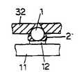
제3도에 있어서, 용기(16)는 얇은 박스형으로서, 플럭스(2)가 얕게 저장되어 있다. 이 플럭스의 깊이(d)는 납땜 보올(1)의 지름(D)의 거의 1/2정도이다. 제4도에서 나타낸 바와 같이, 흡착공(35)의 하부는 테이퍼면(35a)으로 되어 있다. 납땜 보올(1)은 이 테이퍼면(35a)에 진공 흡착되는데, 흡착틀(32)의 하면으로부터의 납땜 보올(1)의 돌출길이(a)는 상기 깊이(d) 보다도 다소 크다.In FIG. 3, the
제3도는 흡착틀(32)을 상하동시키며, 납땜 보올(1)의 하면에 플럭스(2)를 부착시키는 작동을 나타내고 있다. 흡착틀(32)을 하강시킴으로써, 납땜 보올(1)을 용기(16)의 하면에 붙친다. 이 경우, 흡착틀(32)의 자중을 스프링재(40)로서 상쇄시키고, 또한 실린더(38)에 의한 흡착틀(32)의 압압력을 작게 설정하고 있으므로, 납땜 보올(1)은 용기(16)의 저면에 탄성적으로 부드럽게 접촉한다. 더욱이, 흡착공(35)의 하면은 테이퍼면(35a)으로 되어 있기 때문에, 납땜 보올(1)은 접촉의 충격에 의해서도 흡착공(35)에 끼워지지 않는다. 이 때문에, 후에 납땜 보올(1)을 부품(11)의 전극(12)상에 탑재할 때, 납땜 보올(1)이 흡착공(35)으로부터 탈락하지 않아 탑재미스를 일으키는 일은 없다. 또, 납땜 보올(1)은 부드러운 납합금으로서 만들어져 있으나, 용기와의 접촉이 부드럽게 행해지므로, 접촉시의 충격에 의하여 납땜 보올(1)이 변형되는 일도 없다.3 shows the operation of attaching the
또, 제4도를 참조하여 설명한 바와 같이, 납땜 보올(1)의 돌출길이(a)는 플럭스(2)의 깊이(d)보다 길게 하고 있다. 이 때문에, 제3도에 있어서, 쇄선으로 나타낸 바와 같이, 납땜 보올(1)을 용기(16)의 저면에 붙친 상태에서, 흡착틀(32)의 하면이 플럭스(2)에 침적함으로써, 그 하면에 플럭스(2)가 부착하는 일은 없다. 또, 흡착틀(32)을 상승시키면, 제4도에 나타낸 바와 같이, 플럭스(2)의 깊이(d)분만큼, 납땜 보올(1)의 하면에 적량의 플럭스(2)를 부착시킬 수 있다. 이 경우, 흡착틀(32)의 하면에는 다수의 납땜 보올(1)이 진공 흡착되어 있으나, 모든 납땜 보올(1)의 소정깊이(d)만을 플럭스(2)에 침적시킴으로써, 모든 납땜 보올(1)에 균일하게 적정량의 플럭스(2)를 일괄 부착시킬 수 있다.As described with reference to FIG. 4, the protruding length a of the
이상과 같이 납땜 보올(1)에 플럭스(2)를 부착시킨 다음 탑재헤드(20)는 부품(11) 상방으로 이동한다. 그리하여, 탑재헤드가 하강, 상승작동을 행함으로써, 납땜 보올(1)을 부품(11)의 전극(12)상에 탑재한다.After attaching the
제5(a)도 내지 제5(d)도는 납땜 보올(1)의 탑재작동을 상세히 나타내고 있다. 우선, 제5(a)도에 나타낸 바와 같이, 흡착틀(32)은 부품(11)을 향하여 하강한다. 이 하강작동은 모우터(56)가 정회전함으로써 행해진다.5 (a) to 5 (d) show the mounting operation of the
다음, 제5(b)도에 나타낸 바와 같이, 납땜 보올(1)이 전극에 붙으면, 그 반력에 의하여 흡착틀(32)은 제2도에 있어, 실린더(38)의 로드(39)를 상방으로 밀어 올리면서 박스(30)에 대하여 근소하게 부상한다. 케이스(31)의 저부는 터치센서(4)로부터 떨어지고, 납땜 보올(1)이 전극(12)에 접촉한 것이 검지된다. 이 검지에 의하여 모우터(56)는 바로 구동을 정지하고, 흡착틀(32) 하강은 정지한다.Next, as shown in FIG. 5 (b), when the
제5(b)도에 나타낸 바와 같이, 납땜 보올(1)이 전극(12)에 접촉한 상태에서는 모우터(56)의 정회전에 의한 하강력은 납땜 보올(1)을 전극(12)에 밀어 붙치는 힘으로는 작용하지 않는다. 왜냐하면, 납땜 보올(1)이 전극(12)상에 착지하면 케이스(31)나 흡착틀(32)은 박스(30)의 저부로부터 부상하여, 모우터(56)의 정회전에 의한 하강력이 흡착틀(32)에 전달되지 않기 때문이다. 또, 케이스(31)나 흡착틀(32)의 자중도 밀어붙이는 힘으로 작용하지 않는다. 왜냐하면, 케이스(31)와 흡착틀(32)의 자중은 스프링재(40)의 상향 스프링력에 의하여 상쇄되어 있기 때문이다.As shown in FIG. 5 (b), in the state where the
실린더(38)가 작동하여 그 로드(39)가 하방으로 돌출함으로 인해, 가해지는 압압력만이 납땜 보올(1)을 전극(12)에 밀어붙이는 힘으로 작용한다. 즉, 실린더(38)는 납땜 보올(1)을 적당한 힘으로 전극(12)에 밀어붙이기 위한 흡착틀(32)의 압압수단으로 되어 있으며, 그 압압력에 의하여, 납땜 보올(1)을 부품(11)의 전극(12)에 밀어붙이는 힘의 크기를 설정한다. 따라서, 실린더(38)의 로드의 돌출력을 관리함으로써, 납땜 보올(1)을 적당한 힘, 즉 납땜 보올(1)이 흡착공(35)에 끼어든다든지 찌그러지지 않을 정도의 적당한 세기의 힘으로 전극(12)을 밀어붙일 수가 있다.Since the cylinder 38 is actuated and the rod 39 protrudes downward, only the pressing force applied acts as a force for pushing the
다음, 모우터(56)를 근소하게 역회전시켜서, 흡착틀(32)을 근소한 높이(H), 예컨대 0.1∼0.15mm 정도로 상승시킨다. 덧붙여서, 본 실시예에 있어서 납땜 보올(1)의 직경은 1mm 정도이다. 이로 인하여, 납땜 보올(1)의 하면은 전극(12)에서 0.1∼0.15mm 정도의 근소한 높이(H)로 부상하고, 납땜 보올(1)과 전극(12)의 사이에는 점착력이 있는 플럭스(2)가 개재하게 된다(제5(c)도). 거기서 납땜 보올(1)의 진공흡착상태를 해제하고, 모우터(56)를 역회전시켜 흡착틀(32)을 상승시키면, 납땜 보올(1)은 흡착공(35)으로부터 떨어져 전극(12)상에 높이게 된다(제5(d)도). 이 경우, 납땜 보올(1)은, 플럭스(2)의 점착력에 의하여 전극(12)에 흡착되기 때문에, 흡착틀(32)을 상승시키면, 확실히 흡착공(35)으로부터 떨어져 전극(12)상에 탑재된다. 또, 납땜 보올(1)이 흡착공(35)에서 떨어질 때는, 진동기(34)를 구동하여 흡착틀(32)을 초음파 진동시키면, 납땜 보올(1)은 보다 확실히 흡착공(35)으로부터 떨어진다.Next, the
이상과 같이, 부품(11)에 납땜 보올(1)이 탑재되었으며, 부품(11)은 가이드레일(13)을 따라서 다음의 공정으로 송출된다. 다음, 새로운 부품(11)이 가이드레일(13)로 보내어져 상기 작동이 반복된다.As mentioned above, the
제6도는 본 발명의 제2실시예에 의한 도전성 보올의 탑재장치에 있어서 플럭스의 저류부를 나타내고 있다. 용기(16A)는 제1실시예의 용기(16)보다 깊으며, 플럭스(2)도 얼마쯤 깊게 저장되어 있다. 이 실시예는, 스퀴이지(17A)의 하면의 높이를 조정함으로써, 제1실시예와 동일한 깊이(d)로서 플럭스(2)의 표면을 평활하게 하도록 했으며, 이로 인하여 제1실시예와 같은 효과를 얻을 수 있다.6 shows the storage portion of the flux in the mounting apparatus of the conductive bowl according to the second embodiment of the present invention. The
제7도는 본 발명의 제3실시예에 의한 도전성 보올의 탑재장치에 있어서 플럭스의 저류부를 나타내고 있다. 용기(16B) 내의 양측부에는 홈부(162)가 형성되어 있으며, 스퀴이지(17B)중앙의 돌부(161)상을 접동한다. 스퀴이지(17B)의 하면에는 깊이(d)의 오목부(171)가 형성되어 있다. 따라서, 스퀴이지(17B)를 돌부(161)를 따라서 접동시키면 깊이(d)인 플럭스(2)의 막이 생긴다. 이 실시예도 제1실시예와 같은 효과를 얻는다. 그리고, 제2 및 제3실시예에 있어서, 스퀴이지(17A, 17B)가 접동한 직후, 흡착틀(32)이 하강하여 납땜 보올(1)에 플럭스(2)를 부착시키지만, 스퀴이지(17A, 17B)를 접동시킨 후에도 플럭스(2)는 점성을 가지고 있으므로, 당분간은 소정의 깊이(d)를 유지할 수 있다.7 shows the storage portion of the flux in the mounting apparatus of the conductive bowl according to the third embodiment of the present invention.
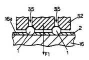
제8(a)도 내지 제8(c)도는 본 발명의 제4실시예에 의한 탑재장치의 도전성 보올 탑재작동의 설명도이다. 압압력 제어부(62)는, 제어부(60)에서의 지령에 의하여 압력원(67)의 압력을 조절하여 실린더(38)를 제어하고, 흡착틀(32)을 하방으로 밀어붙이는 압압력을 조절한다. 그리고, 이 압압력으로서, 납땜 보올(1)에 플럭스를 부착시킬 때의 제1압압력(F1)이 납땜 보올(1) 각각에 대하여 0.5∼20gf 정도로. 또 납땜 보올(1)을 기판(11)의 전극(12)에 탑재할 때의 제2압압력(F2)이 동일하게 25∼100gf 정도로 설정되어 있다. 압압력 제어부(62)는 설정된 압압력(F1, F2)에 맞추어서 그 크기를 적절히 절환하는 것이다.8 (a) to 8 (c) are explanatory views of the conductive bowl mounting operation of the mounting apparatus according to the fourth embodiment of the present invention. The pressurization control part 62 controls the cylinder 38 by adjusting the pressure of the pressure source 67 by the instruction | command from the control part 60, and adjusts the press force which pushes the
본 실시예에서는, 제어부(60)와 압압력 제어부(62)가 흡착틀(32)의 압압력을 변경하는 압압력 변경수단으로 되어 있다.In the present embodiment, the control unit 60 and the pressure control unit 62 serve as pressure pressure changing means for changing the pressure pressure of the
이 도전성 보올의 탑재장치는 상기와 같이 구성되어 있으며, 이어서 그 작동을 설명한다. 제1도에 있어서, 탑재헤드(20)는 공급부(14)의 상방으로 이동한다. 다음, 제2도의 모우터(56)가 구동함으로써 탑재헤드(20)는 하강, 상승하고, 흡착틀(32) 하면의 흡착공(35)에 납땜 보올(1)을 진공흡착에 의하여 픽업한다.The mounting apparatus of this conductive bowl is comprised as mentioned above, and the operation | movement is demonstrated next. In FIG. 1, the mounting
다음, 탑재헤드(20)는 용기(16)의 상방을 향하여 이동한다. 그 도중 탑재헤드(20)는 광원(15)의 상방을 통과하며, 광원(15)은 흡착틀(32)의 하면을 향하여 빛을 조사한다. 제2도에 있어서, 어느 하나의 흡착공(35)에 납땜 보올(1)이 진공 흡착되어 있지 않으면, 즉, 납땜 보올(1)의 흡착미스가 있을 경우 빛은 흡착공(35)을 통하여 광검출센서(37)로 입사한다. 이 때문에, 흡착미스 발생이 판명된다. 픽업미스가 있었을 경우에는 탑재헤드(20)를 공급부(14)의 상방으로 되돌려서 픽업작동을 다시한다.Next, the mounting
한편, 탑재헤드(20)가 납땜 보올(1)의 픽업을 행하는 사이에, 용기(16)상을 스퀴이지(17)가 이동하여 저면(16a)상에 소정의 두께로 플럭스(2)를 공급한다.On the other hand, while the mounting
또한, 흡착미스가 없었을 경우, 탑재헤드(20)는 용기(16)의 상방으로 이동한다. 그리하여 모우터(56)의 구동에 의하여 흡착틀(32)이 상하작동 함으로써, 용기(16)에 저장된 플럭스(2)를 납땜 보올(1) 하면에 부착시킨다(스텝 1). 다음, 탑재헤드(20)는 부품의 상방으로 이동하고, 그곳에서 하강, 상승작동을 행함으로써 납땜 보올(1)을 부품의 전극(12)상에 탑재한다(스텝 2).In addition, when there is no suction miss, the mounting
다음, 제8(a)도 내지 제8(c)도를 참조하여, 납땜 보올(1)에 작용하는 압압력을 설명한다. 우선, 제8(a)도에 나타낸 바와 같이, 상기한 스텝 1에서는 용기(16)의 저면(16a)으로 납땜 볼(1)을 밀어붙일 때, 납땜 보올(1)이나 흡착틀(32)의 하면에 과대한 힘이 작용하지 않도록, 작은 압압력(F1)을 납땜 보올(1)에 가한다. 압압력 제어부(62)는 실린더(38)를 제어하여, 흡착틀(32)을 약한 압압력(F1)으로 하방으로 밀어 내린다. 따라서, 납땜 보올(1)은 약한 힘으로 용기(16)의 저면(16a)에 접촉하며, 플럭스(2)가 흡착틀(32)에 부착하는 일은 없다. 이 때문에, 다음 차례 납땜 보올(1)의 공급 시, 플럭스(2)에 의한 흡착틀(32)의 오염에 기인하여 흡착공(35) 이외 여분의 납땜 보올을 부착하는 일은 없다.Next, with reference to FIGS. 8 (a) to 8 (c), the pressing force acting on the
다음, 제8(b)도에 나타낸 바와 같이, 흡착틀(32)에 의하여, 플럭스(2)가 부착된 납땜 보올(1)을 기판(11)쪽으로 이송한다.Next, as shown in FIG. 8 (b), the
그리고, 제8(c)도에 나타낸 바와 같이, 상술한 스텝 2에서는, 큰 압압력(F2)이 흡착틀(32)에 작용하도록 압압력 제어부(62)는 실린더(38)를 제어한다. 이 때문에, 납땜 보올(1)은 전극(12)으로 확실히 밀어 붙쳐지고, 플럭스(2)가 전극(12)상에 넓게 퍼져 충분한 점착력을 발생한다. 따라서, 진공 해제 시에도 흡착틀(32)의 떠오름은 발생하지 않으며 납땜 보올(1)은 전극(12)상에 탑재된 그대로의 상태이다.And as shown in FIG. 8 (c), in the above-mentioned
이상, 본 발명을 제1부터 제4실시예에 근거하여 설명했으나, 본 발명은, 납땜 보올을 사용하여 범프를 형성할 경우에만 한하지 않으며, 예컨대 금동의 전기저항이 작은 재료로 되어 있는 도전성 보올을 사용할 경우에도 적용할 수 있다. 이 경우, 용기에는 플럭스 아닌 접착제를 저장시켜 놓고, 도전성 보올에 접착제를 도포하고 나서 부품의 전극에 탑재한다. 이 때의 작동은 제1로부터 제4실시예와 동일하다.As mentioned above, although this invention was demonstrated based on 1st-4th Example, this invention is not limited only when bumps are formed using a soldering bowl, For example, the conductive bowl which consists of a material with small electrical resistance of a brass brass This can also be applied when using. In this case, an adhesive rather than a flux is stored in the container, and the adhesive is applied to the conductive bowl and then mounted on the electrode of the part. The operation at this time is the same as in the first to fourth embodiments.
Claims (4)
Translated fromKoreanApplications Claiming Priority (4)
| Application Number | Priority Date | Filing Date | Title |
|---|---|---|---|
| JP07854496AJP3261970B2 (en) | 1996-04-01 | 1996-04-01 | Apparatus and method for mounting conductive ball |
| JP96-78544 | 1996-04-01 | ||
| JP22092896AJP3303684B2 (en) | 1996-08-22 | 1996-08-22 | Conductive ball mounting device and conductive ball mounting method |
| JP96-220928 | 1996-08-22 |
Publications (2)
| Publication Number | Publication Date |
|---|---|
| KR970072227A KR970072227A (en) | 1997-11-07 |
| KR100262844B1true KR100262844B1 (en) | 2000-09-01 |
Family
ID=26419604
Family Applications (1)
| Application Number | Title | Priority Date | Filing Date |
|---|---|---|---|
| KR1019970010904AExpired - Fee RelatedKR100262844B1 (en) | 1996-04-01 | 1997-03-27 | Device and method for mounting conductive bowl |
Country Status (3)
| Country | Link |
|---|---|
| US (1) | US5890283A (en) |
| KR (1) | KR100262844B1 (en) |
| TW (1) | TW370480B (en) |
Cited By (1)
| Publication number | Priority date | Publication date | Assignee | Title |
|---|---|---|---|---|
| KR20180119269A (en)* | 2017-04-25 | 2018-11-02 | (주) 에스에스피 | Semiconductor packaging flux tool |
Families Citing this family (19)
| Publication number | Priority date | Publication date | Assignee | Title |
|---|---|---|---|---|
| KR100268632B1 (en)* | 1996-03-08 | 2000-10-16 | 야마구치 다케시 | Method and apparatus for forming bump |
| US6105245A (en)* | 1997-02-17 | 2000-08-22 | Nippon Steel Semiconductor Corporation | Method of manufacturing a resin-encapsulated semiconductor package |
| JP2850901B2 (en) | 1997-06-02 | 1999-01-27 | 日本電気株式会社 | Ball arrangement jig and manufacturing method thereof |
| US6107181A (en)* | 1997-09-08 | 2000-08-22 | Fujitsu Limited | Method of forming bumps and template used for forming bumps |
| US5985694A (en)* | 1997-09-29 | 1999-11-16 | Motorola, Inc. | Semiconductor die bumping method utilizing vacuum stencil |
| KR100453689B1 (en)* | 1997-12-30 | 2005-02-23 | 앰코 테크놀로지 코리아 주식회사 | Automatic ball size filtering device and method for ball bumping system for semiconductor package manufacturing |
| JPH11340695A (en)* | 1998-05-25 | 1999-12-10 | Sony Corp | Assembling apparatus |
| US6325272B1 (en)* | 1998-10-09 | 2001-12-04 | Robotic Vision Systems, Inc. | Apparatus and method for filling a ball grid array |
| JP3932501B2 (en)* | 1998-12-01 | 2007-06-20 | 澁谷工業株式会社 | Ball mounting device |
| JP3024113B1 (en)* | 1999-01-27 | 2000-03-21 | 株式会社日鉄マイクロメタル | Metal ball arrangement method and arrangement device |
| TW451359B (en)* | 1999-03-16 | 2001-08-21 | Matsushita Electric Industrial Co Ltd | Mounting equipment and mounting method of conductive balls |
| JP3283026B2 (en)* | 1999-04-30 | 2002-05-20 | 新光電気工業株式会社 | Ball-shaped terminal suction device and ball-shaped terminal mounting method |
| JP4598240B2 (en)* | 1999-06-24 | 2010-12-15 | アスリートFa株式会社 | Ball mounting apparatus and ball mounting method |
| US6484927B1 (en)* | 1999-11-05 | 2002-11-26 | Delaware Capital Formation Corporation | Method and apparatus for balling and assembling ball grid array and chip scale array packages |
| AT410499B (en)* | 2000-10-31 | 2003-05-26 | Datacon Semiconductor Equip | DEVICE FOR GUIDING A LINEAR MOVABLE TOOL |
| US6769596B1 (en)* | 2002-11-15 | 2004-08-03 | Qlogic Corporation | Method and system for reworking ball grid arrays |
| WO2004107432A1 (en)* | 2003-05-29 | 2004-12-09 | Fujitsu Limited | Packaging method of electronic component, removing method and devices therefor |
| US8671561B2 (en)* | 2007-05-24 | 2014-03-18 | Shinko Electric Industries Co., Ltd. | Substrate manufacturing method |
| CN109623080A (en)* | 2019-01-24 | 2019-04-16 | 合肥巨动力系统有限公司 | A kind of high efficiency flat wire electric motor winding end welder and welding procedure |
Citations (1)
| Publication number | Priority date | Publication date | Assignee | Title |
|---|---|---|---|---|
| US5284287A (en)* | 1992-08-31 | 1994-02-08 | Motorola, Inc. | Method for attaching conductive balls to a substrate |
Family Cites Families (6)
| Publication number | Priority date | Publication date | Assignee | Title |
|---|---|---|---|---|
| US4292116A (en)* | 1978-04-18 | 1981-09-29 | Tokyo Denki Kagaku Kogyo Kabushiki Kaisha | Apparatus for mounting chip type circuit elements on a printed circuit board |
| US5729894A (en)* | 1992-07-21 | 1998-03-24 | Lsi Logic Corporation | Method of assembling ball bump grid array semiconductor packages |
| US5467913A (en)* | 1993-05-31 | 1995-11-21 | Citizen Watch Co., Ltd. | Solder ball supply device |
| JP2916086B2 (en)* | 1994-10-28 | 1999-07-05 | 株式会社日立製作所 | Electronic component mounting method |
| JP3079921B2 (en)* | 1994-11-28 | 2000-08-21 | 松下電器産業株式会社 | Solder ball mounting device and mounting method |
| US5547740A (en)* | 1995-03-23 | 1996-08-20 | Delco Electronics Corporation | Solderable contacts for flip chip integrated circuit devices |
- 1997
- 1997-03-27KRKR1019970010904Apatent/KR100262844B1/ennot_activeExpired - Fee Related
- 1997-03-28USUS08/825,380patent/US5890283A/ennot_activeExpired - Lifetime
- 1997-03-31TWTW086104100Apatent/TW370480B/ennot_activeIP Right Cessation
Patent Citations (1)
| Publication number | Priority date | Publication date | Assignee | Title |
|---|---|---|---|---|
| US5284287A (en)* | 1992-08-31 | 1994-02-08 | Motorola, Inc. | Method for attaching conductive balls to a substrate |
Cited By (2)
| Publication number | Priority date | Publication date | Assignee | Title |
|---|---|---|---|---|
| KR20180119269A (en)* | 2017-04-25 | 2018-11-02 | (주) 에스에스피 | Semiconductor packaging flux tool |
| KR101944396B1 (en)* | 2017-04-25 | 2019-02-01 | (주)에스에스피 | Semiconductor packaging flux tool |
Also Published As
| Publication number | Publication date |
|---|---|
| KR970072227A (en) | 1997-11-07 |
| TW370480B (en) | 1999-09-21 |
| US5890283A (en) | 1999-04-06 |
Similar Documents
| Publication | Publication Date | Title |
|---|---|---|
| KR100262844B1 (en) | Device and method for mounting conductive bowl | |
| KR100773170B1 (en) | Method and apparatus for the mounting of semiconductor chips | |
| US6193143B1 (en) | Solder bump forming method and mounting apparatus and mounting method of solder ball | |
| KR100722058B1 (en) | Apparatus for the mount of small balls | |
| KR100214098B1 (en) | Mounting device and mounting method of conductive ball | |
| JPH08340001A (en) | Solder bump forming method and apparatus | |
| JP3261970B2 (en) | Apparatus and method for mounting conductive ball | |
| JP3714097B2 (en) | Mounting method of electronic components with bumps | |
| JP3303684B2 (en) | Conductive ball mounting device and conductive ball mounting method | |
| JPH07307344A (en) | Solder ball bonding equipment | |
| JPH1187419A (en) | Apparatus and method for transferring conductive balls | |
| JP4042491B2 (en) | Screen printing apparatus and screen printing method | |
| JP2973889B2 (en) | Apparatus and method for mounting conductive ball | |
| JP2510688B2 (en) | Excess solder removal equipment | |
| JP2002198382A (en) | Bonding paste transfer device, transfer pin, and bonding paste transfer method | |
| JPH11251729A (en) | Transfer device and transfer method for adhesive material | |
| JP2002118125A (en) | Method and device for mounting semiconductor chip | |
| JP3478133B2 (en) | Transfer device for conductive balls | |
| KR100384845B1 (en) | A method for repair of surface mount technology type package and dipping apparatus for applying the same | |
| JP2000288725A (en) | Apparatus for forming plate-like bump material | |
| JPH09326552A (en) | Method and apparatus for applying solder | |
| JP3255029B2 (en) | Apparatus and method for mounting conductive ball | |
| JP2001291951A (en) | Apparatus and method for transferring conductive balls | |
| JPH1117324A (en) | Mounting device for conductive balls | |
| CN120614767A (en) | An automated packaging equipment for patch production |
Legal Events
| Date | Code | Title | Description |
|---|---|---|---|
| A201 | Request for examination | ||
| PA0109 | Patent application | St.27 status event code:A-0-1-A10-A12-nap-PA0109 | |
| PA0201 | Request for examination | St.27 status event code:A-1-2-D10-D11-exm-PA0201 | |
| R17-X000 | Change to representative recorded | St.27 status event code:A-3-3-R10-R17-oth-X000 | |
| PG1501 | Laying open of application | St.27 status event code:A-1-1-Q10-Q12-nap-PG1501 | |
| PN2301 | Change of applicant | St.27 status event code:A-3-3-R10-R13-asn-PN2301 St.27 status event code:A-3-3-R10-R11-asn-PN2301 | |
| R18-X000 | Changes to party contact information recorded | St.27 status event code:A-3-3-R10-R18-oth-X000 | |
| E902 | Notification of reason for refusal | ||
| PE0902 | Notice of grounds for rejection | St.27 status event code:A-1-2-D10-D21-exm-PE0902 | |
| T11-X000 | Administrative time limit extension requested | St.27 status event code:U-3-3-T10-T11-oth-X000 | |
| P11-X000 | Amendment of application requested | St.27 status event code:A-2-2-P10-P11-nap-X000 | |
| P13-X000 | Application amended | St.27 status event code:A-2-2-P10-P13-nap-X000 | |
| E701 | Decision to grant or registration of patent right | ||
| PE0701 | Decision of registration | St.27 status event code:A-1-2-D10-D22-exm-PE0701 | |
| GRNT | Written decision to grant | ||
| PR0701 | Registration of establishment | St.27 status event code:A-2-4-F10-F11-exm-PR0701 | |
| PR1002 | Payment of registration fee | St.27 status event code:A-2-2-U10-U11-oth-PR1002 Fee payment year number:1 | |
| PG1601 | Publication of registration | St.27 status event code:A-4-4-Q10-Q13-nap-PG1601 | |
| PR1001 | Payment of annual fee | St.27 status event code:A-4-4-U10-U11-oth-PR1001 Fee payment year number:4 | |
| PR1001 | Payment of annual fee | St.27 status event code:A-4-4-U10-U11-oth-PR1001 Fee payment year number:5 | |
| PR1001 | Payment of annual fee | St.27 status event code:A-4-4-U10-U11-oth-PR1001 Fee payment year number:6 | |
| PR1001 | Payment of annual fee | St.27 status event code:A-4-4-U10-U11-oth-PR1001 Fee payment year number:7 | |
| PR1001 | Payment of annual fee | St.27 status event code:A-4-4-U10-U11-oth-PR1001 Fee payment year number:8 | |
| PR1001 | Payment of annual fee | St.27 status event code:A-4-4-U10-U11-oth-PR1001 Fee payment year number:9 | |
| R17-X000 | Change to representative recorded | St.27 status event code:A-5-5-R10-R17-oth-X000 | |
| R18-X000 | Changes to party contact information recorded | St.27 status event code:A-5-5-R10-R18-oth-X000 | |
| FPAY | Annual fee payment | Payment date:20090424 Year of fee payment:10 | |
| PR1001 | Payment of annual fee | St.27 status event code:A-4-4-U10-U11-oth-PR1001 Fee payment year number:10 | |
| LAPS | Lapse due to unpaid annual fee | ||
| PC1903 | Unpaid annual fee | St.27 status event code:A-4-4-U10-U13-oth-PC1903 Not in force date:20100509 Payment event data comment text:Termination Category : DEFAULT_OF_REGISTRATION_FEE | |
| PC1903 | Unpaid annual fee | St.27 status event code:N-4-6-H10-H13-oth-PC1903 Ip right cessation event data comment text:Termination Category : DEFAULT_OF_REGISTRATION_FEE Not in force date:20100509 | |
| PN2301 | Change of applicant | St.27 status event code:A-5-5-R10-R13-asn-PN2301 St.27 status event code:A-5-5-R10-R11-asn-PN2301 |