KR100260676B1 - Cooling system using boiling and condensation refrigerant - Google Patents
Cooling system using boiling and condensation refrigerantDownload PDFInfo
- Publication number
- KR100260676B1 KR100260676B1KR1019970008173AKR19970008173AKR100260676B1KR 100260676 B1KR100260676 B1KR 100260676B1KR 1019970008173 AKR1019970008173 AKR 1019970008173AKR 19970008173 AKR19970008173 AKR 19970008173AKR 100260676 B1KR100260676 B1KR 100260676B1
- Authority
- KR
- South Korea
- Prior art keywords
- refrigerant
- passage
- tank
- liquid
- heat dissipation
- Prior art date
- Legal status (The legal status is an assumption and is not a legal conclusion. Google has not performed a legal analysis and makes no representation as to the accuracy of the status listed.)
- Expired - Fee Related
Links
Images


Classifications
- F—MECHANICAL ENGINEERING; LIGHTING; HEATING; WEAPONS; BLASTING
- F28—HEAT EXCHANGE IN GENERAL
- F28D—HEAT-EXCHANGE APPARATUS, NOT PROVIDED FOR IN ANOTHER SUBCLASS, IN WHICH THE HEAT-EXCHANGE MEDIA DO NOT COME INTO DIRECT CONTACT
- F28D1/00—Heat-exchange apparatus having stationary conduit assemblies for one heat-exchange medium only, the media being in contact with different sides of the conduit wall, in which the other heat-exchange medium is a large body of fluid, e.g. domestic or motor car radiators
- F28D1/02—Heat-exchange apparatus having stationary conduit assemblies for one heat-exchange medium only, the media being in contact with different sides of the conduit wall, in which the other heat-exchange medium is a large body of fluid, e.g. domestic or motor car radiators with heat-exchange conduits immersed in the body of fluid
- F28D1/03—Heat-exchange apparatus having stationary conduit assemblies for one heat-exchange medium only, the media being in contact with different sides of the conduit wall, in which the other heat-exchange medium is a large body of fluid, e.g. domestic or motor car radiators with heat-exchange conduits immersed in the body of fluid with plate-like or laminated conduits
- F28D1/0308—Heat-exchange apparatus having stationary conduit assemblies for one heat-exchange medium only, the media being in contact with different sides of the conduit wall, in which the other heat-exchange medium is a large body of fluid, e.g. domestic or motor car radiators with heat-exchange conduits immersed in the body of fluid with plate-like or laminated conduits the conduits being formed by paired plates touching each other
- F28D1/0325—Heat-exchange apparatus having stationary conduit assemblies for one heat-exchange medium only, the media being in contact with different sides of the conduit wall, in which the other heat-exchange medium is a large body of fluid, e.g. domestic or motor car radiators with heat-exchange conduits immersed in the body of fluid with plate-like or laminated conduits the conduits being formed by paired plates touching each other the plates having lateral openings therein for circulation of the heat-exchange medium from one conduit to another
- F28D1/0333—Heat-exchange apparatus having stationary conduit assemblies for one heat-exchange medium only, the media being in contact with different sides of the conduit wall, in which the other heat-exchange medium is a large body of fluid, e.g. domestic or motor car radiators with heat-exchange conduits immersed in the body of fluid with plate-like or laminated conduits the conduits being formed by paired plates touching each other the plates having lateral openings therein for circulation of the heat-exchange medium from one conduit to another the plates having integrated connecting members
- F—MECHANICAL ENGINEERING; LIGHTING; HEATING; WEAPONS; BLASTING
- F25—REFRIGERATION OR COOLING; COMBINED HEATING AND REFRIGERATION SYSTEMS; HEAT PUMP SYSTEMS; MANUFACTURE OR STORAGE OF ICE; LIQUEFACTION SOLIDIFICATION OF GASES
- F25B—REFRIGERATION MACHINES, PLANTS OR SYSTEMS; COMBINED HEATING AND REFRIGERATION SYSTEMS; HEAT PUMP SYSTEMS
- F25B23/00—Machines, plants or systems, with a single mode of operation not covered by groups F25B1/00 - F25B21/00, e.g. using selective radiation effect
- F—MECHANICAL ENGINEERING; LIGHTING; HEATING; WEAPONS; BLASTING
- F28—HEAT EXCHANGE IN GENERAL
- F28D—HEAT-EXCHANGE APPARATUS, NOT PROVIDED FOR IN ANOTHER SUBCLASS, IN WHICH THE HEAT-EXCHANGE MEDIA DO NOT COME INTO DIRECT CONTACT
- F28D15/00—Heat-exchange apparatus with the intermediate heat-transfer medium in closed tubes passing into or through the conduit walls ; Heat-exchange apparatus employing intermediate heat-transfer medium or bodies
- F28D15/02—Heat-exchange apparatus with the intermediate heat-transfer medium in closed tubes passing into or through the conduit walls ; Heat-exchange apparatus employing intermediate heat-transfer medium or bodies in which the medium condenses and evaporates, e.g. heat pipes
- F28D15/0266—Heat-exchange apparatus with the intermediate heat-transfer medium in closed tubes passing into or through the conduit walls ; Heat-exchange apparatus employing intermediate heat-transfer medium or bodies in which the medium condenses and evaporates, e.g. heat pipes with separate evaporating and condensing chambers connected by at least one conduit; Loop-type heat pipes; with multiple or common evaporating or condensing chambers
- H—ELECTRICITY
- H01—ELECTRIC ELEMENTS
- H01L—SEMICONDUCTOR DEVICES NOT COVERED BY CLASS H10
- H01L23/00—Details of semiconductor or other solid state devices
- H01L23/34—Arrangements for cooling, heating, ventilating or temperature compensation ; Temperature sensing arrangements
- H01L23/42—Fillings or auxiliary members in containers or encapsulations selected or arranged to facilitate heating or cooling
- H01L23/427—Cooling by change of state, e.g. use of heat pipes
- H—ELECTRICITY
- H05—ELECTRIC TECHNIQUES NOT OTHERWISE PROVIDED FOR
- H05K—PRINTED CIRCUITS; CASINGS OR CONSTRUCTIONAL DETAILS OF ELECTRIC APPARATUS; MANUFACTURE OF ASSEMBLAGES OF ELECTRICAL COMPONENTS
- H05K7/00—Constructional details common to different types of electric apparatus
- H05K7/20—Modifications to facilitate cooling, ventilating, or heating
- H05K7/2089—Modifications to facilitate cooling, ventilating, or heating for power electronics, e.g. for inverters for controlling motor
- H05K7/20936—Liquid coolant with phase change
- F—MECHANICAL ENGINEERING; LIGHTING; HEATING; WEAPONS; BLASTING
- F28—HEAT EXCHANGE IN GENERAL
- F28D—HEAT-EXCHANGE APPARATUS, NOT PROVIDED FOR IN ANOTHER SUBCLASS, IN WHICH THE HEAT-EXCHANGE MEDIA DO NOT COME INTO DIRECT CONTACT
- F28D15/00—Heat-exchange apparatus with the intermediate heat-transfer medium in closed tubes passing into or through the conduit walls ; Heat-exchange apparatus employing intermediate heat-transfer medium or bodies
- F28D15/02—Heat-exchange apparatus with the intermediate heat-transfer medium in closed tubes passing into or through the conduit walls ; Heat-exchange apparatus employing intermediate heat-transfer medium or bodies in which the medium condenses and evaporates, e.g. heat pipes
- F28D2015/0216—Heat-exchange apparatus with the intermediate heat-transfer medium in closed tubes passing into or through the conduit walls ; Heat-exchange apparatus employing intermediate heat-transfer medium or bodies in which the medium condenses and evaporates, e.g. heat pipes having particular orientation, e.g. slanted, or being orientation-independent
- H—ELECTRICITY
- H01—ELECTRIC ELEMENTS
- H01L—SEMICONDUCTOR DEVICES NOT COVERED BY CLASS H10
- H01L2924/00—Indexing scheme for arrangements or methods for connecting or disconnecting semiconductor or solid-state bodies as covered by H01L24/00
- H01L2924/0001—Technical content checked by a classifier
- H01L2924/0002—Not covered by any one of groups H01L24/00, H01L24/00 and H01L2224/00
Landscapes
- Engineering & Computer Science (AREA)
- Physics & Mathematics (AREA)
- Thermal Sciences (AREA)
- Microelectronics & Electronic Packaging (AREA)
- Mechanical Engineering (AREA)
- General Engineering & Computer Science (AREA)
- Computer Hardware Design (AREA)
- Condensed Matter Physics & Semiconductors (AREA)
- General Physics & Mathematics (AREA)
- Power Engineering (AREA)
- Sustainable Development (AREA)
- Life Sciences & Earth Sciences (AREA)
- Cooling Or The Like Of Semiconductors Or Solid State Devices (AREA)
- Cooling Or The Like Of Electrical Apparatus (AREA)
- Devices That Are Associated With Refrigeration Equipment (AREA)
Abstract
Translated fromKoreanDescription
Translated fromKorean본 발명은, 반도체 소자 및 전기 장치의 발열체와 같은 고온 매체로부터 발생된 열을 흡수하여 고온 매체를 냉각하기 위하여 냉매를 비등 및 응축시키는 냉각장치에 관한 것이다.BACKGROUND OF THE
고온 매체인 발열체로부터 발생된 열을 냉각하기 위한 비등 및 응축냉매를 이용한 다수의 냉각장치들이 공지되어 있다. 이들 공지된 냉각장치 중에서, 일본국 특개소 56-147457에 개시된 바와 같이, 장치 내에서, 비등 및 증발되어 상승하는 냉매와 방열기에서 냉각되어 냉매탱크로 되돌아오는 액냉매의 플러딩(flooding), 즉, 상호간의 충돌 현상을 방지하여 열교환 작동을 효율적으로 수행할 수 있는 냉각장치가 있다.BACKGROUND OF THE INVENTION Many chillers are known using boiling and condensation refrigerants for cooling heat generated from a heating element which is a hot medium. Among these known cooling apparatuses, as disclosed in Japanese Patent Laid-Open No. 56-147457, in the apparatus, the boiling and evaporating refrigerant and the liquid refrigerant which is cooled in the radiator and returned to the refrigerant tank, namely, There is a cooling device that can efficiently perform heat exchange operations by preventing collision between each other.
일본국 특개소 56-147457에 개시된 냉각장치는 발열체로부터 발생된 열에 의해 비등 및 기화되는 냉매를 수용하는 냉매탱크; 냉매탱크와 연통하며 대체로 균일한 직경을 가지는 유입통로; 유입통로와 연통하는 복수 개의 방열통로를 갖는 방열기; 및 방열기에서 응축 및 액화된 냉매가 냉매탱크로 되돌아가는 유출통로를 포함한다.The cooling device disclosed in Japanese Patent Laid-Open No. 56-147457 includes a refrigerant tank containing a refrigerant boiled and vaporized by heat generated from a heating element; An inflow passage communicating with the refrigerant tank and having a generally uniform diameter; A radiator having a plurality of heat dissipation passages in communication with the inflow passages; And an outlet passage through which the refrigerant condensed and liquefied in the radiator returns to the refrigerant tank.
상기 냉각장치에 따르면, 정상 작동(방열량이 작은)의 경우, 냉매의 기포가 발생되고, 냉매는 기상 상태(가스 상태)로 유입통로를 통해 흘러 열을 전달한다. 즉, 기상 상태의 냉매는 방열통로을 정의하는 벽체와 직접 접촉하게 되며, 그에 의해, 열이 벽체에 직접 전달된다(응축열 전달).According to the cooling device, in the normal operation (the heat dissipation amount is small), bubbles of the refrigerant are generated, and the refrigerant flows through the inflow passage in the gaseous state (gas state) to transfer heat. That is, the refrigerant in the gaseous state is in direct contact with the wall defining the heat dissipation passage, whereby heat is transferred directly to the wall (condensation heat transfer).
그러나, 방열량이 증가함에 따라, 냉매의 기포 발생은 심해지고, 일부 냉매는 액상 상태로 유입통로를 통해 흐르며, 기상 및 액상 냉매에 의해 열이 전달된다. 액냉매는 응축에 의해 열을 전달하는 것이 아니라, 강제 대류, 즉, 방열 통로 벽체와의 액냉매의 열전달에 의해 열을 전달한다. 강제 대류에 의한 열전달 효율은 응축에 의한 열전달 효율의 1/10 내지 1/20이다.However, as the amount of heat dissipation increases, bubble generation of the refrigerant increases, some of the refrigerant flows through the inflow passage in the liquid state, and heat is transferred by the gaseous phase and the liquid phase refrigerant. The liquid refrigerant transfers heat by forced convection, that is, by heat transfer of the liquid refrigerant to the heat dissipation passage wall, rather than transfer heat by condensation. The heat transfer efficiency by forced convection is 1/10 to 1/20 of the heat transfer efficiency by condensation.
일본국 특개소 56-147457에 개시된 냉각장치의 냉매탱크와 연통하는 유입통로는 대체로 균일한 직경을 가지므로, 비교적 많은 양의 액냉매가 방열통로 속을 흐르게 되며, 이점은 전체의 냉각장치의 방열 특성이 현저하게 저하되는 문제점을 야기시킨다.Since the inflow passage communicating with the refrigerant tank of the cooling apparatus disclosed in Japanese Patent Laid-Open No. 56-147457 has a generally uniform diameter, a relatively large amount of liquid refrigerant flows into the heat dissipation passage, and the advantage is that heat dissipation of the entire cooling apparatus is achieved. It causes a problem that the property is significantly degraded.
또한, 일본국 특개소 56-147457에 개시된 냉각장치의 냉매탱크와 연통하는 유입통로는 대체로 균일한 직경을 가지므로, 유입통로 내에서의 유동저항이 비교적 작다. 따라서, 상승하여 유입통로에 도달한 기상 냉매는 유입통로의 입구에서 떨어진 유입통로의 단부에 정체되며, 유입통로의 단부가 고온으로 가열될 수 있다. 냉각장치에 복수 개의 방열통로가 제공되더라도, 단부에서 떨어진 방열통로의 부분 온도가 상대적으로 낮게 되어, 열이 효율적으로 방열될 수가 없게 된다. 결과적으로, 냉각장치의 방열 성능은 방열기 크기와 비교해서 낮아지게 된다.Further, since the inflow passage communicating with the refrigerant tank of the cooling apparatus disclosed in Japanese Patent Laid-Open No. 56-147457 has a generally uniform diameter, the flow resistance in the inflow passage is relatively small. Therefore, the gaseous refrigerant that rises and reaches the inflow passage is stagnated at the end of the inflow passage away from the inlet of the inflow passage, and the end of the inflow passage can be heated to a high temperature. Even if a plurality of heat dissipation passages are provided in the cooling device, the partial temperature of the heat dissipation passage away from the end becomes relatively low, and heat cannot be efficiently dissipated. As a result, the heat dissipation performance of the chiller is lowered compared to the radiator size.
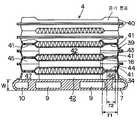
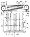
도1은 본 발명의 제1실시예에 따른 냉각장치의 측면도이며;1 is a side view of a cooling apparatus according to a first embodiment of the present invention;
도2는 도1의 Ⅱ-Ⅱ 선을 따라 보여진 단면도이며;FIG. 2 is a cross sectional view taken along line II-II of FIG. 1;
도3은 도1의 Ⅲ-Ⅲ 선을 따라 보여진 단면도이며;3 is a cross-sectional view taken along line III-III of FIG. 1;
도4A 및 도4B는 방열관을 형성하기 위한 성형 판재의 측면도 및 평면도이며;4A and 4B are a side view and a plan view of a molded sheet material for forming a heat dissipation tube;
도5는 도1의 Ⅴ-Ⅴ 선을 따라 보여진 단면도이며;FIG. 5 is a cross sectional view taken along the line VV of FIG. 1; FIG.
도6은 본 발명의 제2실시예에 따른 냉각장치의 부분 측단면도이며;6 is a partial side cross-sectional view of a cooling apparatus according to a second embodiment of the present invention;
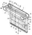
도7은 도6의 냉각장치의 사시도이며;7 is a perspective view of the cooling device of FIG. 6;
도8은 도7의에서의 Ⅷ-Ⅷ 선을 따라 보여진 단면도이며;FIG. 8 is a cross sectional view taken along the line VII-VII in FIG. 7; FIG.
도9는 도7의 Ⅸ-Ⅸ 선을 따라 보여진 단면도이며;FIG. 9 is a sectional view taken along the line VII-VII of FIG. 7; FIG.
도10은 도7의 Ⅹ-Ⅹ 선을 따라 보여진 단면도이며;FIG. 10 is a sectional view taken along the line VII-VII of FIG. 7; FIG.
도11은 도7에 도시된 냉각장치에서 복귀통로 및 방열통로의 내부 구조의 설명도이며;11 is an explanatory view of the internal structure of the return passage and the heat dissipation passage in the cooling apparatus shown in FIG. 7;
도12A는 내부핀의 정면도이며;12A is a front view of an inner pin;
도12B는 도12A의 ⅩⅡВ-ⅩⅡВ선을 따라 보여진 단면도이며;FIG. 12B is a cross sectional view along line XXXII-XIIV of FIG. 12A; FIG.
도13은 냉각장치의 변형예의 측면도이며;13 is a side view of a modification of the cooling device;
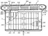
도14는 본 발명의 제3실시예에 따른 냉각장치의 정면도이며;14 is a front view of a cooling apparatus according to a third embodiment of the present invention;
도15는 도14의 냉각장치의 측면도이며;15 is a side view of the cooling device of FIG. 14;
도16A 및 도16B는 연결관을 구성하는 프레스 가공 판재의 측면도 및 평면도이며;16A and 16B are side and top views of a press-formed sheet material constituting the connecting pipe;
도17A 및 도17B는 방열관을 구성하는 프레스 가공 판재의 측면도 및 평면도이며;17A and 17B are a side view and a plan view of a press-formed sheet material constituting the heat dissipation tube;
도18A 및 도18B는 도17A 및 도17B의 프레스 가공 판재의 부분 확대도이며;18A and 18B are partially enlarged views of the press-formed sheet material of FIGS. 17A and 17B;
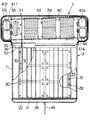
도19는 본 발명의 제4실시예에 따른 냉각장치의 정면도이며;19 is a front view of a cooling apparatus according to a fourth embodiment of the present invention;
도20은 제5실시예에 따른 냉각장치의 정면도이며;20 is a front view of a cooling apparatus according to the fifth embodiment;
도21은 제5실시예에 따른 냉각장치의 측면도이며;21 is a side view of a cooling apparatus according to the fifth embodiment;
도22는 도20의 Ⅹ?-Ⅹ? 선을 따라 보여진 단면도이며;FIG. 22 shows the pattern of FIG. 20; A cross-sectional view along the line;
도23은 본 발명의 제6실시예에 따른 냉각장치의 정면도이며;23 is a front view of a cooling apparatus according to the sixth embodiment of the present invention;
도24는 본 발명의 제6실시예에 따른 냉각장치의 측면도이며;24 is a side view of a cooling apparatus according to a sixth embodiment of the present invention;
도25는 도23의 ⅩⅩⅤ-ⅩⅩⅤ 선을 따라 보여진 단면도이며;FIG. 25 is a cross-sectional view taken along line VV-VV of FIG. 23;
도26은 종래 냉각장치에서의 냉매 유동상태를 나타낸 개략도이며;26 is a schematic diagram showing a refrigerant flow state in the conventional cooling apparatus;
도27은 종래의 냉각장치에서 방열기의 외부핀의 온도분포를 나타낸 도면이며;27 is a view showing the temperature distribution of the outer fins of the radiator in the conventional cooling apparatus;
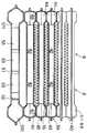
도28은 본 발명의 제7실시예에 따른 냉각장치의 사시도이며;28 is a perspective view of a cooling apparatus according to a seventh embodiment of the present invention;
도29는 도28의 ⅩⅩⅠⅩ-ⅩⅩⅠⅩ 선을 따라 보여진 단면도이며;FIG. 29 is a cross sectional view taken along line XXXI-XXXI in FIG. 28;
도30은 도28의 ⅩⅩⅩ-ⅩⅩⅩ 선을 따라 보여진 단면도이며;30 is a sectional view taken along the line VII-VII of FIG. 28;
도31은 도28의 ⅩⅩⅩⅠ-ⅩⅩⅩⅠ 선을 따라 보여진 단면도이며;FIG. 31 is a cross-sectional view taken along the line XI-XI of FIG. 28;
도32A 및 도32B는 프레스 가공 판재의 측면도 및 평면도이며;32A and 32B are side and top views of a press-formed sheet material;
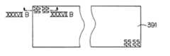
도33은 도28의 ⅩⅩⅩⅠⅠⅤ-ⅩⅩⅩⅠⅠⅤ 선을 따라 보여진 단면도이며;FIG. 33 is a cross sectional view along line XXXV-XIV of FIG. 28; FIG.
도34A 및 도34B는 도33에 도시된 내부핀의 부분 확대 측면도 및 단면도이며;34A and 34B are partially enlarged side and sectional views of the inner pin shown in FIG. 33;
도35는 도34에 도시된 내부핀의 부분적 사시도이며;35 is a partial perspective view of the inner pin shown in FIG. 34;
도36은 다른 내부핀의 부분 사시도이며;36 is a partial perspective view of another inner pin;
도37A는 제3내부핀의 평면도이며;37A is a top view of a third inner pin;
도37B는 도37A의 ⅩⅩⅩⅤⅠⅠВ-ⅩⅩⅩⅤⅠⅠВ 선을 따라 보여진 부분 단면도이며;FIG. 37B is a partial cross sectional view taken along VIIV-IVVIВ line of FIG. 37A; FIG.
도37C는 도37B의 내부핀의 부분 사시도이다.FIG. 37C is a partial perspective view of the inner pin of FIG. 37B. FIG.
따라서, 본 발명의 첫째 목적은 방열 성능의 저하를 방지할 수 있는 냉각장치를 제공하는 것이다.Therefore, the first object of the present invention is to provide a cooling device that can prevent the deterioration of the heat radiation performance.
본 발명의 두 번째 목적은 액상 냉매(액냉매)가 방열통로로 유입되는 것을 억제할 수 있는 냉각장치를 제공하는 것이다.A second object of the present invention is to provide a cooling apparatus that can suppress the introduction of a liquid refrigerant (liquid refrigerant) into the heat dissipation passage.
본 발명의 세 번째 목적은 각각 대체로 동일한 방열율로 열을 방열할 수 있는 복수 개의 방열통로가 제공된 방열기를 갖는 냉각장치를 제공하는 것이다.A third object of the present invention is to provide a cooling device having a radiator provided with a plurality of heat dissipation passages, each of which is capable of dissipating heat at substantially the same heat dissipation rate.
본 발명의 네 번째 목적은 복수 개의 방열통로가 제공되며, 대체로 동일한 유량으로 냉매를 방열통로로 분배할 수 있는 냉각장치를 제공하는 것이다.A fourth object of the present invention is to provide a plurality of heat dissipation passages, and to provide a cooling apparatus capable of distributing refrigerant into the heat dissipation passages at substantially the same flow rate.
본 발명의 일측면에 따르면, 방열통로에서의 응축에 의한 열전달 면적이 증가될 수 있도록, 냉매탱크로부터 흐르면서 방열통로의 내면에 점착하는 액냉매의 양을 감소시키기 위한 점착량 감소수단이 방열기에 제공된다.According to an aspect of the present invention, the heat dissipation means is provided with a pressure-sensitive adhesive reducing means for reducing the amount of liquid refrigerant flowing from the refrigerant tank to the inner surface of the heat dissipation passage so that the heat transfer area due to condensation in the heat dissipation passage can be increased do.
본 발명의 다른 측면에 따르면, 냉각장치는 냉매탱크로부터 기-액상 혼합(the gas-liquid mixed) 냉매가 흐르는 유입통로, 냉매를 냉매탱크로 내보내기 위한 유출통로, 및 유입통로를 유출통로와 연통시키는 방열통로가 제공된 방열기를 가지며, 상기 유입통로는 기-액상 혼합냉매가 유동하는 방향으로 교대로 형성된 소정 직경을 갖는 대구경부 및 상기 대구경부의 직경보다 작은 직경을 갖는 소구경부를 갖는다.According to another aspect of the present invention, the cooling device has an inflow passage through which the gas-liquid mixed refrigerant flows from the refrigerant tank, an outlet passage for exporting the refrigerant to the refrigerant tank, and an inflow passage communicating with the outlet passage. It has a heat radiator provided with a heat dissipation passage, the inflow passage has a large diameter portion having a predetermined diameter alternately formed in the direction in which the gas-liquid mixed refrigerant flows and a small diameter portion having a diameter smaller than the diameter of the large diameter portion.
방열량이 많을 경우, 냉매는 냉매탱크 내에서 기포를 발생시키며, 기상 및 액상의 냉매가 유입통로 속으로 흐른다. 유입통로에서 냉매 유동 방향으로 형성된 소구경부는 인접한 방열통로로 흐르는 액냉매를 억제한다. 소구경부에 의해 진행이 막혀진(진행이 방해된) 액냉매는 냉매탱크로 되돌려 진다. 방열통로 속으로 흐르는 액냉매량은 소구경부에 의해 감소되므로, 응축에 의한 열전달 면적이 증가 될 수 있다.When the amount of heat radiation is large, the refrigerant generates bubbles in the refrigerant tank, and the gaseous and liquid refrigerants flow into the inflow passage. The small diameter portion formed in the refrigerant flow direction in the inflow passage suppresses the liquid refrigerant flowing to the adjacent heat dissipation passage. The liquid refrigerant whose progress is blocked by the small diameter part is returned to the refrigerant tank. Since the amount of liquid refrigerant flowing into the heat dissipation path is reduced by the small diameter part, the heat transfer area due to condensation may be increased.
냉매탱크에는 고온 매체로부터 전달된 열에 의해 증발된 가스질 냉매 및 액냉매가 상승하는 증기 통로, 및 방열기에서 냉각되어 응축된 액냉매가 하강하는 응축액 통로가 내부에 제공된다. 그러므로, 비등 냉매와 응축냉매가 서로 충돌하는 플러딩이 방지될 수 있다.The refrigerant tank is provided with a vapor passage in which the gaseous refrigerant evaporated by heat transferred from the hot medium and the liquid refrigerant rise, and a condensate passage in which the liquid refrigerant cooled and condensed in the radiator descends. Therefore, flooding in which the boiling refrigerant and the condensation refrigerant collide with each other can be prevented.
본 발명의 다른 측면에 따르면, 냉각장치는 액냉매복귀부가 제공된 방열기를 갖는다. 상기 액냉매복귀부는 냉매탱크출구와 일체로 형성되고 방열기의 내부 직경보다 작은 직경을 가지며 액냉매의 흐름을 막기 위한 소구경 개구부를 갖는 유입복귀실 및 유출복귀실과 연통되어 흐름이 막힌 액냉매를 냉매탱크로 되돌리는 복귀통로가 구비된다.According to another aspect of the invention, the cooling device has a radiator provided with liquid refrigerant return. The liquid refrigerant return unit is formed integrally with the refrigerant tank outlet and has a diameter smaller than the inner diameter of the radiator and communicates with the inflow return chamber and the outlet return chamber having a small diameter opening for preventing the flow of the liquid refrigerant, and the liquid refrigerant blocked the flow. A return passage back to the tank is provided.
소구경 개구부의 최하부는 액냉매복귀부의 유입복귀실의 바닥면보다 소정의 높이만큼 높게 위치될 수 있다. 따라서, 냉매탱크로부터 비등하여 냉매탱크출구를 통해 흐른 기-액상 혼합냉매의 액냉매는 효율적으로 진행이 막아질 수 있다.The lowermost portion of the small diameter opening may be positioned higher by a predetermined height than the bottom surface of the inflow return chamber of the liquid refrigerant returning portion. Therefore, the liquid refrigerant of the gas-liquid mixed refrigerant flowing through the refrigerant tank outlet by boiling from the refrigerant tank can be efficiently prevented from proceeding.
소구경 개구부는 펀칭 가공에 의해 대체로 타원형 또는 사각 형상으로 형성될 수 있다. 따라서, 냉매탱크출구를 통과한 기-액상 혼합냉매의 액냉매가 효율적으로 진행이 막아지므로, 방열기의 유효방열면적은 증가되고 방열 성능이 향상될 수 있다.The small diameter openings may be formed in a generally oval or square shape by punching. Therefore, since the liquid refrigerant of the gas-liquid mixed refrigerant passing through the refrigerant tank outlet is effectively prevented, the effective heat dissipation area of the radiator can be increased and the heat dissipation performance can be improved.
방열통로의 각 바닥면은, 응축된 액냉매를 방열통로에서 냉매탱크로 원활하게 되돌리기 위하여, 냉매탱크출구에서 냉매탱크입구를 향해 하방으로 경사진다. 따라서, 방열통로의 바닥면에 정체하는 응축액냉매의 양은 감소되며, 응축에 위한 열전달 면적이 증가될 수 있으며, 가스질 냉매는 효율적으로 응축될 수 있다.Each bottom surface of the heat dissipation passage is inclined downward from the coolant tank outlet toward the coolant tank inlet in order to smoothly return the condensed liquid refrigerant from the heat dissipation passage to the coolant tank. Therefore, the amount of condensate refrigerant stagnating on the bottom surface of the heat dissipation passage is reduced, the heat transfer area for condensation can be increased, and the gaseous refrigerant can be condensed efficiently.
본 발명의 또 다른 목적 및 장점은 첨부된 도면을 참조한 다음의 바람직한 실시예의 상세한 설명으로부터 보다 명백해 질 것이다.Further objects and advantages of the present invention will become more apparent from the following detailed description of preferred embodiments with reference to the attached drawings.
이하, 첨부된 도면을 참조하여 본 발명의 제1실시예를 설명한다.Hereinafter, a first embodiment of the present invention will be described with reference to the accompanying drawings.
도1은 본 발명에 따른 제1실시예에서의 냉각장치의 측면도이다. 도2는 도1의 Ⅱ-Ⅱ 선을 따라 보여진 단면도이다. 도3은 도1의 Ⅲ-Ⅲ 선을 따라 보여진 단면도이다. 도4A 및 도4B는 방열관을 형성하기 위한 프레스 가공 판재의 측면도 및 평면도이다. 도5는 도1의 Ⅴ-Ⅴ 선을 따라 보여진 단면도이다.1 is a side view of a cooling apparatus in a first embodiment according to the present invention. FIG. 2 is a cross-sectional view taken along line II-II of FIG. 1. 3 is a cross-sectional view taken along line III-III of FIG. 4A and 4B are side and plan views of a press-formed sheet material for forming a heat dissipation tube. FIG. 5 is a cross-sectional view taken along the line VV of FIG. 1.
제1실시예에 따른 냉각장치(1)는, 일반적 전기 조정기, 전기 자동차 등에 포함된 인버터 회로를 구성하는 고온 매체인 IGBT 모듈(2)을 냉각한다. 냉각장치(1)는 냉매탱크(3), 방열기(4) 및 냉각팬(5)을 포함한다.The
도1에 도시된 바와 같이, IGBT 모듈(2)은 냉매탱크(3)의 벽체 외면에 볼트(6)로 고정된다. 될 수 있으면, 열전도 그리스(grease)가 IGBT 모듈의 방열판과 냉매탱크(3)의 외벽 사이에 제공된다.As shown in FIG. 1, the
냉매탱크(3)는 알루미늄 블록재를 압출 가공하므로써 형성된 중공의 압출부재(7) 및 상기 압출부재(7)의 상하 개방단에 각각 부착된 앤드 캡(22a, 22b)을 포함한다. 냉매의 유입 및 유출구로서의 압출부재(7)의 다른 개방단은 방열기(4)와 연통한다.The
도2 및 도3에 도시된 바와 같이, 압출부재(7)는, IGBT 모듈(2)이 부착되는 그 벽체의 너비 및 길이보다 작은 두께W의 평판 형상을 가진다. 압출부재(7)의 내부는, 수직으로 연장된 격벽(30, 31, 32)에 의해, 길이방향으로 압출부재(7)를 통과하는 증기 통로(9), 응축액 통로(10), 및 비작동 통로(33)로 구획된다. 증기 통로(9)의 냉매탱크출구(35) 및 응축액 통로(10)의 냉매탱크입구(36)는, 방열기(4)(방열관(39))가 연결 판재(34)에 의해 연결되는 압출부재(7)의 벽체 일부분에 형성된다(도1참조).As shown in Figs. 2 and 3, the
격벽(30, 31, 32)의 각 상단부를 잘라내므로써, 복수 개의 증기 통로(9), 응축액 통로(10) 및 비작동통로(33)는 압출부재(7)의 상단 조금 아래 부분에서 개방된다. 각 증기 통로(9)의 개방단 및 응축액 통로(10)의 개방단은 증발 냉매용 냉매탱크출구(35) 및 응축액냉매용 냉매탱크입구(36)로서 각각 작용한다. 볼트(6)가 조여지는 내부 나사 구멍이 통로(10, 11)가 형성되지 않은 압출부재(7)의 두꺼운 벽 부분(7a)에 형성된다.By cutting off each upper end of the
냉매탱크출구(35)는 비작동 통로(33)의 상부에 형성된다. 도3에서 파선으로 지시된 두개의 증기통로(9) 사이의 격벽(31) 및 증기통로(9)와 비작동 통로(33) 사이의 격벽(32)의 상부는 밀링 가공과 같은 부가적인 기계 가공에 의해 제거되어, 냉매탱크출구(35)가 증기통로(9)와 연통된다. IGBT 모듈(2)을 냉매탱크(3)에 장착하기 위한 볼트(6)가 조여지는 내부 나사 구멍(37)이 격벽(30, 31, 32)에 형성된다. 비작동 통로(33)는, 압출부재(7)가 압출 가공될 때, 응축액 통로(10)와 균형을 이루도록 형성되며, 상기 비작동 통로는 응축액 통로로서는 사용되지 않는다. 그러므로, 비작동 통로(33)의 형성은 반드시 필요한 것이 아니다.The
앤드 캡(22)은 압출부재(7)의 상하 단부에 납땜된다. 상부 앤드 캡(22a)은 압출부재(7)의 상부 개방단을 폐쇄하도록 압출부재(7)의 상단에 접합된다. 하부 앤드 캡(22b)은, 증기통로(9), 응축액 통로(10) 및 비작동 통로(33)를 서로 연통시키는 하부 연통로(38)가 압출부재(7)의 하단과 하부 앤드 캡(22b) 사이에 형성되도록, 압출부재(7)의 하단에 접합된다.The
방열기(4)는 소위 드로운 컵 타입(drown cup type) 열교환기이다, 도4A에 도시된 바와 같이, 방열기(4)는 복수 개의 방열관(39)을 평행하게 교대로 적층하므로써 형성되며, 상기 각각의 방열관(39)은 두개의 대칭형의 얇은 프레스 가공 판재(40)를 접합하므로써 형성된다. 방열기(4)는 연결판재(34)에 의해 냉매탱크(3)에 접합된다(도5 참조).The
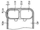
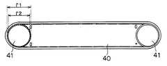
도5에 도시된 바와 같이, 연결판재(34)는, 압출부재(7)의 냉매탱크출구(35) 및 냉매탱크입구(36)를 덮도록 압출부재(7)의 외부면에 밀봉하여 부착된다. 압출부재(7)의 외벽면에 의해 둘러싸인 공간을 가지므로, 연결판재(34)는, 소정의 직경 r1을 가지며 냉매탱크(3)의 탱크출구(35)와 연통하는 유입복귀챔버(461)(큰 개구부, 확장부분, 제1확장부), 소정의 직경 r1을 가지며 탱크입구(36)와 연통하는 유출복귀챔버(471), 및 유입복귀챔버(461)와 유출복귀챔버(471) 사이를 상호 연결하는 복귀통로(421)를 갖는 액냉매복귀유닛(341)(점착량 감소수단)을 구성한다.As shown in FIG. 5, the connecting
유입복귀챔버(461)의 내경보다 작은 소구경 r2를 갖는 소구경 개구부(411)(소구경부, 제한 개구부)가, 탱크출구(35)의 반대측, 유입복귀챔버(461)의 벽체 부분에 형성된다. 액냉매복귀유닛(341)은 소구경 개구부(411)를 통하여 방열관(39)과 연통한다.A small diameter opening portion 411 (small diameter portion, limited opening portion) having a small diameter r2 smaller than the inner diameter of the
방열관(39)은 두개의 대체로 사각형인 프레스 가공 판재(40)의 외주 단부를 접합하여 형성된 중공 구조이다(도4A 참조). 두개의 프레스 가공 판재(40)는 알루미늄과 같은 고열전도성을 갖는 금속 판재를 프레스 가공하여 동일한 형상으로 형성되며, 각각의 프레스 가공 판재(40)의 마주보는 각각의 단부에는 작은 직경을 갖는 소구경 개구부(41)(소구경부, 제한 개구부)이 제공된다. 도4B에 도시된 바와 같이, 소구경 개구부(41)는 대체로 타원 또는 사각형으로 펀칭 가공된 구멍이다. 본 실시예에서, 소구경 개구부(41)는 직경 r2를 가지며, 직경 r2보다 큰 직경 r1을 갖는 대구경 개구부(대구경부)가 각각의 작은 개구부(41)의 주위에 형성된다.The
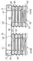
각각의 방열관(39)은 그 내부의 정중심부에 평편한 방열통로(42)를 형성하며, 양단부는 각각 큰 직경을 갖는 유입연통챔버(44)(냉매탱크출구(35)에 연결된 공간) 및 유출연통챔버(45)(냉매탱크입구(36)에 연결된 공간)를 형성한다. 복수 개의 방열관(39)을 적층하여 형성된 방열기(4)는 복수의 방열통로(42), 각 방열통로(42)의 일단에 연결된 유입통로, 및 각 방열통로(42)의 다른 단에 연결된 유출통로를 포함한다. 유입통로는 복수 개의 유입연통챔버(44)를 적층하므로써 형성된다. 유출통로는 복수 개의 유출연통챔버(45)를 적층하므로써 형성된다. 상기 유입통로 및 유출통로에는, 인접한 유입연통챔버(44) 사이 및 인접한 유출연통챔버(45) 사이에 소구경 개구부(41)가 각각 제공된다. 따라서, 각각의 유입통로 및 유출통로는 그 내부에서 교대로 배치된 복수 개의 대구경부(r1) 및 소구경부(r2)를 갖도록 형성된다. 펀칭 가공에 의해 형성된 소구경 개구부(41)는 하나의 인접한 유입연통챔버(44)로부터 다른 유입연통챔버로 흐르는 액냉매의 유통량을 억제하는 제한 개구부로서 작용한다.Each of the
본 실시예의 경우, 방열관(39)은 냉매탱크(3) 측면에 대체로 수직이며, 냉매탱크(3)에 수용된 액냉매의 유면에 대해 대체로 수평이 되도록 적층된다. 그러나, 방열관(39)에 고인 액냉매를 냉매탱크(3)로 효율적으로 되돌리기 위하여, 방열관(39)은 냉매탱크(3)의 측면에서 소정 간격을 두고 상방으로 위치되도록 경사지면서 적층될 수도 있다.In the case of this embodiment, the
방열핀(16)은, 도5에 도시된 바와 같이, 인접한 방열관(39) 사이에 개입된다. 최외측 방열관(39)의 외측의 프레스 가공 판재(40)에는 소구경 개구부(41)가 없이 제공된다. 소구경 개구부(41)가 제공된 프레스 가공 판재(40)가 채용될 경우, 소구경 개구부(41)는 앤드 플레이트(도시되지 않음) 등에 의해 프레스 가공 판재(40)의 외측에서 폐쇄될 수도 있다.The
또한, 액냉매복귀유닛(341)의 소구경 개구부(411)는 방열관(39)의 소구경 개구부(41)와 연통하며, 그에 의해, 복수 개의 유입연통챔버(44)로 구성된 유입통로가 유입복귀챔버(461)와 연통하게 된다. 또한, 복수 개의 유출연통챔버(45)로 구성된 유출통로는, 마찬가지로, 유출복귀챔버(471)와 연통하게 된다. 방열기(4)는 이상 설명한 바와 같이 구성된다.Further, the small
도1에 도시된 바와 같이, 축류팬과 같은 냉각팬(5)이 방열기(4)의 상면에 배치되어 방열기(4)를 향해 수직으로 공기를 송풍한다. 냉각팬(5)은 방열기(4)의 하류측에 배치된 흡입팬 또는 방열기(4)의 상류측에 배치된 강제 통풍팬일 수 있다. 또한, 냉각팬(5)은 횡류팬일 수 있으며, 방열기(4)의 정면 및 배면에 배치될 수 있다.As shown in Fig. 1, a cooling
이하, 제1실시예의 작동을 설명한다.The operation of the first embodiment will be described below.
도6을 참조하면, 냉매는 IGBT 모듈(2)로부터 발생되고 전달된 열에 의해 비등하게 된다. 냉매는 기포가 되어 증기통로(9)를 통해 상승하며, 냉매탱크출구(35)를 통해 유출연통챔버(461) 속으로 흘러간다. 그 후, 냉매는 유출연통챔버(461)로부터 유입연통챔버(44)로 흘러가서 방열관(39)의 방열통로(42)로 분배된다(도5 참조). 방열통로(42)를 통해 흐르는 증발 냉매는 냉각팬(5)으로부터 송풍된 공기에 의해 저온으로 냉각된 방열통로(42)의 내면 및 내부핀(43)의 표면에서 응축되며, 응출열을 방열한다. 냉매는 작은 물방울 형태로 맺히며, 방열통로(42)의 바닥면을 흐르면서 방열기(4)의 유출측 연통챔버(45) 속을 흘러간다. 응축액냉매는 냉매탱크입구(36)에서 응축액 통로(10)로 흐르며, 응축액 통로(10)를 통해 흘러 내려가고 앤드 캡(22b)에 형성된 통로 바닥면을 통해 증기통로(9)로 되돌아간다. 증발 냉매에 의해 방열된 응축열은 프레스 가공 판재(40)를 통해 방열핀(16)으로 전달되며, 방열핀(16)으로부터 각각 짝을 이룬 인접한 방열관(39) 사이에서 유동하는 공기로 방열된다.Referring to Figure 6, the refrigerant is boiled by the heat generated and transferred from the IGBT module (2). The refrigerant is bubbled and rises through the
도6을 참조하면, 방열량이 많은 경우, 냉매는 냉매탱크(3)에서 기포를 발생시키고 기상 냉매 및 액상 냉매 모두는 유입복귀챔버(461)로 흘러간다. 도6에서, 빈 원(blank circle)은 기상 냉매를 나타내며, 채워진 원(solid circle)은 액상 냉매를 나타낸다. 유입복귀챔버(461)는 소구경 개구부(411)에 의해 혼합냉매의 액냉매가 방열통로로 흐르는 것을 억제한다. 즉, 소구경 개구부(411)는 액냉매의 진행을 방해한다. 진행이 막힌 액냉매는 복귀통로(421)를 통해 냉매탱크(3)로 복귀한다. 그러므로, 소구경 개구부(411)를 통해 방열통로(42)로 흐르는 기-액상 혼합냉매의 액냉매량은 감소된다. 따라서, 방열통로(42)에서 열전달을 위한 유효 면적을 증가시키는 것이 가능하게 된다.Referring to Fig. 6, when the amount of heat radiation is large, the refrigerant generates bubbles in the
다시 말하면, 방열기(4)의 유입연통챔버(461)는 교대로 형성된 대구경부(r1) 및 소구경부(r2)를 포함하며, 소구경부(r2)는 기-액상 혼합냉매의 액냉매가 인접한 방열통로(42)로 유동하는 것을 억제한다. 그러므로, 소구경부(r2)를 통해 방열통로(42)로 흘러가는 기-액상 혼합냉매의 액냉매의 양이 감소되며, 그에 의해, 방열통로(42)에서의 응축 열전달을 위한 유효면적의 증가가 가능하게 된다.In other words, the
방열량이 커질 경우, 냉매는 냉매탱크(3)에서 기포를 발생하며, 많은 기포량을 포함하는 기-액상 혼합냉매(즉, 기상 및 액상 냉매의 혼합체)는 탱크출구(35)를 향해 흐른다(도3 참조). 이때, 유입통로가 일직선이면, 즉, 유입통로가 균일한 직경을 가지면, 액상 냉매의 많은 량이 기상 냉매와 함께 방열통로(42)로 흐르며, 방열통로(42)의 입구 부분이 액냉매로 채워진다. 상기 상태에서, 열은 응축에 의해서 뿐만이 아니라 강제 대류에 의해서 전달된다. 강제 대류의 열전달 효율은 응축에 의한 열전달 효율보다 훨씬 낮으므로, 방열기(4)의 방열 성능은 저하된다. 본 실시예에서는 유입통로에 소구경 개구부(411)가 제공되므로, 방열통로(42)로의 액냉매의 유동이 억제될 수 있다. 결과적으로, 열은 방열통로(42)에서 주로 응축에 의해 냉매로부터 방열기(4)로 전달되며, 방열기(4)의 방열 성능의 저하가 방지될 수 있다. 소구경 개구부(41)는 방열통로(42)로의 불균일한 냉매 분배를 방지하며, 그에 의해, 냉매는 방열통로(42)로 균일하게 분배되고 방열기(4)의 방열 성능의 저하가 방지될 수 있다.When the heat dissipation amount increases, the refrigerant generates bubbles in the
또한, 방열량이 크게 될 경우, 냉매탱크에서 냉매 내부에 포함된 기포는 증가하게 되며, 액냉매의 수위가 상승하게 된다. 액냉매의 수위가 상승될 때, 탱크는 봉쇄 수단(blockage)으로서 작용한다. 그러므로, 액냉매가 방열통로(42)로 흐르는 것이 방지된다.In addition, when the heat radiation amount is large, bubbles contained in the refrigerant in the refrigerant tank is increased, the level of the liquid refrigerant is increased. When the level of the liquid refrigerant rises, the tank acts as a blockage. Therefore, the liquid refrigerant is prevented from flowing into the
소구경 개구부(411)의 최하부는 유입복귀챔버(461)의 바닥면보다 (r1-r2)/2의 소정 높이만큼 높게 위치된다. 소정 높이를 갖는 부분은 냉매탱크출구(35)를 통과한 냉매가 자중에 의해 떨어지는 것을 막는다. 따라서, 방열통로(42)로의 액냉매 흐름은 억제될 수 있다. 냉매탱크출구(35)는 대체로 타원 또는 사각형이므로, 자중에 의해 흐르는 액냉매의 흐름을 효율적으로 막을 수 있게 된다.The lowermost part of the small-
드로운 컵 타입 방열기(4)를 채용하므로써, 냉매탱크(3)에 부착된 IGBT 모듈(2)의 수가 증가하고 IGBT 모듈에 의해 발생된 총열량이 증가하는 경우라도, 방열기(4)의 용량은 용이하게 변경될 수 있다. 즉, 하나씩 차례로 동일 형상의 방열관(39)을 적층하므로써, 방열기(4)의 용량이 용이하게 변경될 수 있다. 그러므로, 방열되는 총열량에 대응하는 용량을 갖는 방열기(4)가 저렴한 비용으로 제공될 수 있다. 증기통로(9)는, 압출부재(7)의 격벽(31, 32)의 상부를 절단하므로써, 간단히 탱크출구(35)와 연통될 수 있으므로, 냉매의 순환은 부가적인 별도의 부품을 사용하지 않고서도 저렴한 비용으로 조절될 수 있다.By employing the draw
방열기(4)는, 응축액냉매를 방열기(4)에서 냉매탱크(3)(응축액 통로(10))으로 되돌리기 위하여, 냉매탱크(3)를 향해 경사지도록 배치될 수도 있다.The
도3에 도시된 바와 같이, 냉매탱크(3)의 하부 앤드 캡(22b) 대신에, 격벽(30. 31, 32)의 하단부는 밀링 가공과 같은 추가적인 기계 가공에 의해 제거될 수도 있으며, 평편한 플레이트(48)(앤드 캡(22))이 압출부재(7)의 하단에 납땜되기도 한다. 이 경우, 하부 앤드 캡(22)(평편한 플레이트(48))의 제작이 용이하게 된다.As shown in FIG. 3, instead of the
본 실시예의 냉매탱크출구(35) 및 냉매탱크입구(36)는 각각 다른 높이로 형성되더라도, 본 실시예에서, 냉매탱크출구(35) 및 냉매탱크입구(36)는 동일한 높이로 형성될 수도 있다. 또한, 냉매탱크출구(35) 및 냉매탱크입구(36)는 동일한 형상으로 형성될 수도 있다.Although the
제1실시예에 따른 냉각장치(1)의 냉매탱크(3)는 압출 가공으로 형성된 압출부재(7)에 의해 구성된다. 따라서, 압출부재(7)를 압출 가공하기 위한 압출 다이의 제작비용은 부분품(parts)을 프레스 가공하기 위한 프레스 다이의 비용보다 저렴하게 된다. IGBT 모듈(2)의 수가 증가될 경우, IGBT 모듈(2)이 복수층(길이방향)으로 배치되면, 압출부재(7)는 적당한 길이로 절단되므로써 이용될 수 있다. 따라서, 프레스 가공 제품이 채용될 때, 사용되는 프레스 다이를 새로 제공할 필요가 없게 되며, 다이 제작비용이 크게 감소하게 된다.The
냉매탱크(3)가 압출부재(7)를 채용하여 구성되므로, IGBT 모둘(2)이 부착되는 압출부재(7)의 충분한 표면 강도가 확보될 수 있다. 그러므로, 압출부재(7)의 지지벽의 장착면(외부면)과 IGBT 모듈(2) 사이의 접촉열저항이, 냉매탱크가 프레스 가공된 얇은 부재와 IGBT 모듈을 조립하므로써 구성되는 경우에 비하여, 감소될 수 있게 된다. 따라서, 냉각장치(1)의 방열 성능은 향상될 수 있다. 또한, 압출부재(7)를 채용하므로써, 내부 나사가 형성된 구멍을 형성하기 위한 충분한 두께를 갖는 두꺼운 벽체부(7a)의 확보가 가능하게 되며, 증기통로(9) 및 응축액 통로(10)의 형상을 자유롭게 설정하는 것이 가능하게 되며, 이것은 냉매탱크(3)가 평편한 형상으로 형성될 때, 압력밀봉성(pressure tightness) 향상이라는 점에서 유리하다. 즉, 냉매의 양을 감소시키기 위하여 냉매탱크(3)를 평편한 형상으로 형성하는 것은 압력밀봉성 관점에서는 불리하지만, 증기통로(9) 및 응축액 통로(10)의 형상을 적당하게 설정하므로써, 충분한 밀봉성이 확보될 수 있다.Since the
또한, 두꺼운 벽체부(7a)에 내부 나사를 형성하기 위한 충분한 면적이 제공될 경우, 동일한 압축부재(7)가, 여러 나사 피치를 갖는 장착나사는 여러 형식의 IGBT 모듈용으로 채용될 수 있다. 다시 말하면, 서로 다른 나사 피치를 갖는 장착나사를 여러 형식의 IGBT 모듈이 동일한 압출부재(7)를 채용한 냉매탱크(3)에 장착될 수 있다. 따라서, 냉매탱크(3)는 소형화 가능하게 되며, 여러 나사 피치를 갖는 IGBT 모듈의 여러 형식을 위한 표준화된 냉매탱크(3)를 채용할 경우, 그 비용은 감소될 수가 있다.In addition, when a sufficient area for forming the internal screws is provided in the
냉매탱크(3)의 내부는 증기통로(9)와 응축액 통로(10)로 분할되므로, 냉매탱크(3)에서의 비등 냉매의 흐름과 응축냉매의 흐름은, 비등 냉매와 응축냉매가 충돌하는 플러딩이 방지될 수 있도록, 서로 확실하게 분리되며, 또한, 높은 방열 성능의 확보가 가능하게 된다. 증기통로(9) 및 응축액 통로(10)가 서로 분리되므로, 응축액 통로(10)를 통하여 유동하는 냉매는 IGBT 모듈(2)에 의해 발생된 열에 의해 직접 가열되지 않으며, 냉매의 온도는 증기통로(9)에서의 냉매 온도보다 낮도록 설정된다. 저온 냉매는 연통로(17)를 통하여 응축액 통로(10)로부터 증기통로(9)로 서서히 흘러 IGBT 모듈(2)을 효율적으로 냉각한다.Since the inside of the
이하, 본 발명의 제2실시예를 설명한다.Hereinafter, a second embodiment of the present invention will be described.
도7은 도6의 냉각장치의 사시도이다. 도8은 도7에서의 ⅤⅢ-ⅤⅢ 선을 따라 보여진 단면도이다. 도9는 도7에서의 Ⅸ-Ⅸ 선을 따라 보여진 단면도이다. 도10은 도7에서의 Ⅹ-Ⅹ 선을 따라 보여진 단면도이다.7 is a perspective view of the cooling apparatus of FIG. FIG. 8 is a cross-sectional view taken along the line VIII-VIII in FIG. 7. 9 is a cross-sectional view taken along the line VII-VII in FIG. FIG. 10 is a cross-sectional view taken along the line VII-VII in FIG. 7.
도7 내지 도10을 참조하면, 제2실시예의 경우, 방열관(39)은 방열기(4)에서 응축된 액냉매가 냉매탱크(3)로 원활하게 되돌아가도록 경사진다.7 to 10, in the second embodiment, the
냉매탱크(3)는, 예를 들면, 알루미늄 블록을 압출 가공하여 형성된 압축부재(7) 및 압출부재(7)의 하부 개방단에 부착된 앤드 캡(22)을 포함한다.The
압출부재(7)의 내부는 수직으로 연장된 격벽(30, 31, 32)에 의해 압출부재(7)를 길이방향으로 통과하는 증기통로(9), 응축액 통로(10), 및 비작동 통로(33)로 구획된다. 증기통로(9)의 개방단 및 응축액 통로(10)의 개방단은 냉매탱크출구(35) 및 냉매탱크입구(36)로서 각각 작용한다.The interior of the extruded
앤드 캡(22)은 압출부재(7)와 동일한 알루미늄으로 제작되며, 압출부재(7)의 증기통로(9), 응축액 통로(10) 및 비작동 통로(33)를 서로 연통시키는 하부 연통로(38)를 형성하도록, 압출부재(7)의 하단에 일체로 납땜된다.The
도7에 도시된 바와 같이, 앤드 캡(22)에는, 냉각장치(1)가 세척되며, 냉매가 공급되고, 배기가 수행되는 냉매 봉입용 튜브(49)가 부착된다. 냉각장치(1)를 배기시킬 경우, 그 내부에 냉매를 채운 후, 냉각장치(1)는 반전되며, 방열기(4)는 냉매의 포화 증기압이 대기압보다 높은 온도로 유지된 온수 탱크에 잠긴다. 따라서, 증발 냉매의 비중이 공기보다 크므로, 냉각장치(1) 내의 냉매는 증발되어 공기를 방출하게 된다. 배기 후, 냉매를 냉각장치(1) 내에 봉입하기 위하여 튜브(49)는 코킹되고 용접 등에 의해 밀봉된다.As shown in Fig. 7, the
방열기(4)는 소위 드로운 컵 타입 열교환기이다. 제1실시예에서의 방열기(4)와 마찬가지로, 방열기(4)는 두 개의 판재(50)를 접합하므로써 형성된 연결관(51)(연결부재) 및 복수 개의 동일 중공 형상의 방열관(39)을 적층하므로써 구성된다.The
연결관(51)은 냉매탱크(3)의 상단을 수직으로 덮으며, 연결관(51)의 내부는, 도10에 도시된 바와 같이, 격벽(52)에 의해 냉매탱크(3)의 냉매탱크출구(35)와 연통하는 유입챔버(511) 및 냉매탱크입구(36)와 연통하는 유출챔버(512)로 구획된다. 도8 및 도10에 도시된 바와 같이, 복수 개의 내부핀(53)이 연결관(51)의 유출챔버(512) 내에 배치되며, 판재(50)에 형성된 복수 개의 포지션닝 리브(50a)에 의해 지지된다.The
도10에 도시된 바와 같이, 두 개의 연결판재(34) 즉, 판상부재가 액냉매복귀유닛(341)을 형성하기 위하여 서로 접합된다. 액냉매복귀유닛(341)은 연결관(51)의 측벽에 밀봉되어 접합되어 냉매탱크출구(35)를 통해 비작동 통로(33) 및 증기통로(9)와 연통하는 유입복귀챔버(461), 냉매탱크입구(36)를 통해 응축액 통로(10)와 연통하는 유출복귀챔버(471), 및 유입복귀챔버(461)와 유출복귀챔버(471) 사이를 상호 연결하는 복귀통로(421)를 형성한다. 내부핀(43)은 복귀통로(421)에 배치된다(도11 참조). 프레스 가공 판재(40)와 마찬가지로, 연결판재(34)에는 소구경 개구부(411)가 제공된다. 복귀챔버(461, 471)는 소구경 개구부(411)를 통하여 방열관(39)과 연통한다.As shown in Fig. 10, two connecting
액냉매복귀유닛(341)은 소정의 내경 r1을 가지며 냉매탱크(3)의 냉매탱크출구(35)와 연통된 유입복귀챔버(461)(대구경 개구부), 탱크출구(36)에 연결된 유출복귀챔버(471)(대구경부), 및 유입복귀챔버(461)와 유출복귀챔버(471) 사이를 상호 연결하는 복귀통로(421)로 구성된다. 유입복귀챔버(461)의 직경보다 작은 직경을 갖는 소구경 개구부(411)(소구경부, 제한 개구부)가 탱크출구(35)의 반대측, 유입복귀챔버(461)의 부분에 형성된다.The liquid
도4에 도시된 바와 같이, 방열관(39)은, 예를 들면, 알루미늄으로 제작된 두 개의 프레스 가공 판재(40)의 외주연부를 접합하므로써 형성된 중공의 구조이다. 방열관(39)은, 그의 대향 단부에, 소구경 개구부(41)를 갖는 유입통로 및 유출통로를 갖는다.As shown in Fig. 4, the
각각의 방열관(39)은 그 내부 정중심부에 평편한 방열통로(42)를 형성하며, 양단부에는 각각 큰 직경을 갖는 유입연통챔버(44)(냉매탱크출구(35)에 연결된 공간) 및 유출연통챔버(45)(냉매탱크입구(36)에 연결된 공간)가 각각 형성된다. 유입통로는 복수 개의 유입연통챔버(44)를 적층하므로써 형성된다. 유출통로는 복수 개의 유출연통챔버(45)를 적층하므로써 형성된다. 유입통로 및 유출통로에는 소구경 개구부(41)가 인접한 유입연통챔버(44) 사이 및 인접한 유출연통챔버(45) 사이에 제공된다. 따라서, 각각의 유입통로 및 유출통로는 그 내부에 교대로 배치된 복수 개의 대구경부(r1) 및 소구경부(r2)를 갖도록 형성된다. 펀칭 가공에 의해 형성된 소구경 개구부(41)는 하나의 인접한 유입연통챔버(44)로부터 다른 인접한 유입연통챔버로 유동하는 액냉매량을 억제하는 제한 개구부로서 작용한다.Each of the
도11에 도시된 바와 같이, 얇은 알루미늄 판재로 제작된 파형의 내부핀(43)이 방열관(39)의 평편한 방열통로(42)에 배치된다. 도12A는 내부핀(43)의 평면도이며, 도12B는 도12A의 ?В-?В 선을 따라 보여진 단면도이다.As shown in FIG. 11, a corrugated
도10에 도시된 바와 같이, 방열관(39)은 연결관(51)의 일측에 적층되고 소구경 개구부(41)를 통해 서로 연통한다. 방열관(39)은 판재(50)의 소구경 개구부(41)(방열관(39)의 일측의) 및 방열관(39)의 소구경 개구부를 통하여 연결관(51)과 연통한다. 방열관(39)은 전체적으로 경사지면서 연결관(51)에 부착되며, 그에 의해, 도7에 도시된 바와 같이, 유입연통챔버(44)의 높이가 유출연통챔버(45)의 높이보다 높게 된다. 판재(50)에 형성된 리브(50b)는 방열관(39)에 접합된 판재(50) 부분을 보강한다.As shown in Fig. 10, the
방열관(39)의 소구경 개구부(41)는 액냉매복귀유닛(341)의 소구경 개구부(41)와 연통한다. 유입복귀챔버(461) 및 유입연통챔버(44)는 서로 연통하며, 유출복귀챔버(471) 및 유출연통챔버(45)는 서로 동시에 연통된다. 방열기(4)는 이상 설명한 것과 같이 구성된다.The small
이하, 제2실시예의 작동을 설명한다.The operation of the second embodiment will be described below.
IGBT 모듈에 의해 발생되고 전달된 열에 의해 가열된 냉매는 기포로 비등하고 증기통로(9)를 통해 상승한다. 탱크출구(35)를 통해 연결관(51)의 유입챔버(511)로 흘러간 후, 냉매는 유입챔버(511)로부터 유출통로, 즉, 유입복귀챔버(461) 및 유입연통챔버(44)로 흘러가며, 방열과(39)의 방열통로(42)로 분배된다. 방열통로(42)를 통해 흐르는 증발 냉매는 냉각팬(5)(도8 참조)에 의해 송풍된 공기에 의해 냉각된 방열통로(42)의 내부 표면 및 내부핀의 표면에서 응축하여 응축열을 방출한다. 냉매는 물방울 형태로 맺혀 떨어지고 방열통로(42)의 바닥면을 따라 유출통로, 즉, 유출연통챔버(45) 및 유출복귀챔버(471)로 흘러간다. 그 후, 응축액냉매는 연결관(51)의 유입챔버 및 냉매탱크(3)의 탱크입구(36)를 통해 유출통로로부터 응축액 통로(10)로 흐른다. 응축액 통로(10)를 통해 흘러 내려간 후, 냉매는 앤드 캡 내에 형성된 하부 연결통로(38)를 통해 증기통로(9)로 되돌아간다.Refrigerant heated by the heat generated and transferred by the IGBT module is boiled with bubbles and rises through the vapor passage (9). After flowing into the
방열량이 크게 될 때, 냉매는 냉매탱크(3)내에서 기포를 발생하고, 기상 및 액상 냉매 모두가 유입복귀챔버(461)로 흘러간다. 유입복귀챔버(461)의 소구경 개구부(411)는 혼합냉매의 액냉매가 방열통로로 흐르는 것을 억제한다. 즉, 혼합 냉매의 액냉매는 소구경 개구부(411)에 의해 진행이 막힌다. 진행이 방해된 액냉매는 복귀통로(421)를 통해 냉매탱크(3)로 되돌려진다. 그러므로, 소구경 개구부(411)를 통해 방열통로(42)로 흐르는 기-액상 혼합냉매에서의 액냉매의 양은 감소된다. 따라서, 방열통로(42)에서의 응축열 전달을 위한 유효면적의 증가가 가능하게 된다.When the heat dissipation amount becomes large, the refrigerant generates bubbles in the
다시 말하면, 방열기(4)의 유입연통챔버(461)는 교대로 형성된 대구경부(r1) 및 소구경부(r2)를 포함하며, 소구경부(r2)는 기-액상 혼합냉매의 액냉매가 인접한 방열통로(42)로 흘러 들어가는 것을 억제한다. 그러므로, 소구경부(r2)를 통해 방열통로(42)로 흐르는 기-액상 혼합냉매에서의 액냉매량이 감소되며, 그에 의해, 방열통로(42)에서의 응축열 전달을 위한 유효면적의 증대가 가능하게 된다.In other words, the
제2실시예의 경우, 제1실시예와 마찬가지로, 소구경 개구부(41)가 유입통로 내에 제공되며, 소구경 개구부(41)는 방열통로(42)로의 불균일한 냉매 분배를 방지하므로, 냉매는 방열통로(42)로 균일하게 분배되며, 방열기(4)의 방열 성능의 저하가 방지될 수 있다.In the case of the second embodiment, similarly to the first embodiment, the
방열관(39)는 경사지면서 연결관(51)에 부착되므로, 응축액냉매는 원활하게 방열통로(42)에서 냉매탱크(3)를 향해 흐를 수 있다. 결과적으로, 방열통로(42)의 바닥면에서 정체하는 응축액냉매의 양이 감소되고 증발 냉매가 효율적으로 응축될 수가 있다. 그러므로, 필요 냉매량이 감소되고 그 비용이 절감될 수 있다.Since the
증기통로(9)는 복수의 격벽(31)에 의해 분리되므로, 증기통로(9)에서의 가스질 냉매의 흐름이 원활하게 되며, 격벽(31)은, 방열성능이 향상될 수 있도록, 유효비등면적을 증가시킨다. 또한, 격벽(31)은 그 내부에서의 정 및 부압에 대한 냉매탱크(3)의 강도를 향상시키며, IGBT 모듈(2)이 부착된 벽면의 변형을 방지한다.Since the
도13에 도시된 바와 같이, 제1 및 제2 실시예의 변형예처럼, 방열기(4)는 연결판재(34)의 양측에 부착되어 방열성능을 역시 향상시킬 수도 있다.As shown in Fig. 13, as in the modification of the first and second embodiments, the
이하, 본 발명의 제3실시예를 설명한다.Hereinafter, a third embodiment of the present invention will be described.
도14는 제3실시예에 따른 냉각장치의 정면도이다. 도15는 도14의 냉각장치의 측면도이다.14 is a front view of a cooling apparatus according to the third embodiment. 15 is a side view of the cooling apparatus of FIG.
제3실시예에서, 냉각장치(1)는 도7에 도시된 냉각장치(1)의 변형예이다. 제3실시예에서의 냉각장치(1)는 도7에 도시된 냉각장치(1)와 다른 부분을 주로 참조하여 설명하며, 도7에 도시된 냉각장치와 유사하거나 동일한 작용을 하는 부분 및 구성품은 동일한 참조 번호로 지시되며, 그의 설명은 생략된다.In the third embodiment, the
도14 및 도15를 참조하면, 도7에 도시된 방열기와 마찬가지로, 방열기(4)는 동일한 중공 형상의 복수 개의 방열관(39) 및 두 개의 판재(50)의 접합으로 형성된 연결관(51)을 적층하므로써 형성된 소위 드로운 컵 타입 열교환기이다.14 and 15, like the radiator shown in FIG. 7, the
연결관(51)은 도16A에 도시된 두 개의 판재(50)를 접합하므로써 형성된다. 도16B에 도시된 바와 같이, 연결관(51)의 각각의 대향 단부에는 냉매탱크(3)에서 비등되어 증발된 냉매가 방열기(4)로 흘러가는 두개의 유출 개구부(541, 542) 및 방열기(4)에서 응축된 액냉매가 냉매탱크(3)로 복귀되는 두개의 복귀 개구부(544, 545)가 각각 제공된다. 도14에 도시된 바와 같이, 연결관(51)은 냉매탱크(3)의 상단부를 덮는다. 연결관(51)의 내부는 격벽(52)에 의해 냉매탱크(3)에 형성된 냉매탱크출구(35)에 연결된 유입챔버(511)(도시되지 않음) 및 냉매탱크(3)에 형성된 냉매탱크입구(36)에 연결된 유출챔버(512)(도시되지 않음)로 구획된다.The connecting
도16B에서, 유출개구부(542) 및 복귀개구부(544) 주위의 점선은 도16A에 도시된 개구부 주위의 돌출부를 나타낸다. 유지부(543, 546)가 개구부(541, 542) 사이 및 개구부(544, 545) 사이에 각각 형성된다. 복수 개의 핀(53)은 연결관(51)의 유입챔버에 삽입된다.In Fig. 16B, the dotted lines around the
도17A에 도시된 바와 같이, 방열관(39)은 두개의 프레스 가공 알루미늄 판재의 외주연부를 접합하므로서 형성된 중공 구조이다. 도17B에 도시된 바와 같이, 소구경 개구부(411, 412)가 방열관(39)의 일단부에 형성되며, 소구경 개구부(414, 415)는 방열관(39)의 다른 단부에 형성된다. 유지부(413, 416)는 소구경 개구부(411, 412) 사이 및 소구경 개구부(414, 415) 사이에 형성된다.As shown in Fig. 17A, the
도15에 도시된 바와 같이, 방열관(39)은 연결관(51)의 양측면에 적층되며, 핀(16)은 인접하게 적층된 방열관(39) 사이에 배치된다. 돌출부는 도17A에 도시된 바와 같은 소구경 개구부(411, 415) 주위에 형성되며, 소구경 개구부(412, 414)가, 소구경 개구부(411, 415) 주위에 각각 형성된 돌출부를 수용하기 위한 소정 너비를 갖는 구멍으로 각각 형성된다. 판재(40)를 적층할 때, 그의 소구경 개구부(412)와 다른 판재의 소구경 개구부(415)는 조립되며, 소구경 개구부(411)와 다른 판재의 소구경 개구부(414)가 각각 조립된다. 판재(40)가 조립된 후, 판재(40)는 납땜 등에 의해 함께 접합된다. 복수의 판재(40)는 각각의 소구경 개구부(411, 412, 414, 415)를 통해 서로 연통하여 방열관(39)을 구성한다.As shown in Fig. 15, the
연결관(51)은, 그의 복귀개구부(544, 545) 및 유출개구부(541, 542)를 프레스 가공 판재(40)의 소구경 개구부(411, 412, 414, 415)와 연통시키므로써, 방열관(39)과 연통한다. 방열관(39)의 최외측 프레스 가공 판재(40)는 소구경 개구부 없이 제공된다. 그러나, 최외측 프레스 가공 판재(40)에는 소구경 개구부가 제공될 수도 있으며, 소구경 개구부는 앤드 플레이트(도시되지 않음)에 의해 프레스 가공 판재(40)의 외측으로부터 폐쇄되기도 한다.The connecting
방열관(39)은 그 내부의 정중심부에 방열통로(42)를 형성하며, 복수 개의 방열통로(42)가 형성된다. 도12에 도시된 바와 같은 얇은 알루미늄 판재로 형성된 파형의 내부핀이 방열통로(42) 내에 배치된다.The
다시 말하면, 유입통로는 두개의 프레스 가공 판재(40)의 접합에 의해 각각 형성된 복수 개의 유입연통챔버(44)를 적층하므로써 형성되며, 유출통로는 두개의 프레스 가공 판재(40)의 접합에 의해 각각 형성된 복수 개의 유출연통챔버(45)를 적층함으로써 형성된다. 펀칭 가공에 의해 형성된 소구경 개구부(411, 412, 414, 415)는 하나의 인접한 유입연통챔버(44)로부터 액냉매가 다른 유입연통챔버로 흐르는 것을 억제하는 제한 개구부로서 작용한다.In other words, the inflow passage is formed by stacking a plurality of
소구경 개구부(411, 412, 414, 415)(소구경부, 제한 개구부)는 횡방향으로 직경 r2를 가지며, 직경 r2보다 큰 횡방향 직경 r1을 갖는 대구경 개구부(대구경부)가 소구경 개구부(411, 412, 414, 415) 주위에 형성된다.The small-
각각의 소구경 개구부(411, 412, 414, 415)는 수직 방향으로 직경 r4를 가지며, 직경 r4의 2배보다 큰 수직 방향 직경 r3(r3 a2 Sr4)을 갖는 대구경 개구부(대구경부)가 소구경 개구부(411, 412, 414, 415) 주위에 형성된다.Each of the small-
도7에 도시된 것과 마찬가지로, 방열관(39)은 전체적으로 경사지면서 연결관(51)에 부착되며, 그에 의해, 유입연통챔버(44)의 높이는 유출연통챔버(45)의 높이보다 높게 된다. 도18A 및 도18B에 도시된 바와 같이, 각 방열관(39)을 구성하는 프레스 가공 판재(40)에서, 소구경 개구부(411)의 최하부(411a)의 높이는 방열통로(42)를 형성하는 프레스 가공 판재(40) 부분의 최하부의 높이보다 거리 d1만큼 낮으며, 소구경 개구부(414)의 저부(414a)의 높이는 방열통로(42)를 형성하는 프레스 가공 판재(40) 부분의 최하부의 높이보다 거리 d2만큼 낮아진다. 상기 거리 d1 및 d2는 동일하거나 서로 다를 수 있다.As shown in FIG. 7, the
이하, 제3실시예의 작동을 설명한다.The operation of the third embodiment will be described below.
IGBT 모듈(2)로부터 발생되어 전달된 열에 의해 가열된 냉매는 비등하며, 기포로서 증기통로(9)를 통해 상승하며, 탱크출구(35)를 통해 연결관(51)의 유입챔버(511) 속으로 흐른다. 그 후, 냉매는 유입챔버(511)로부터 소구경 개방부(541, 542)를 통해 유입통로, 즉, 유입복귀챔버(461) 및 유입연통챔버(44)로 흘러가며, 방열관(39)의 방열통로(42)로 분배된다. 방열통로(42)를 통해 흐르는 증발 냉매는, 냉각팬(5)으로부터 송풍된 공기에 의해 저온으로 냉각된 방열통로(42)의 내부면 및 내부핀 표면에서 응축되어 응출열을 방출한다(도9 참조). 냉매는 물방울 형태로 맺혀 떨어지고 방열통로(42)의 저면(40a)을 따라 유출통로, 즉, 유출연통챔버(42) 및 유출복귀챔버(471)로 흘러간다. 그 후, 액냉매 유출통로에서 연결관(51)의 소구경 개구부(544, 545)를 통해 유출통로에서 유출챔버(512)로 흘러간다. (이 경우에, 냉매의 대부분은 하부 소구경 개구부(544)의 하부 주위에서 흐른다). 그 후, 냉매는 냉매탱크(3)의 탱크입구(36)를 통해 응축액 통로(10)로 흘러간다. 응축액 통로(10)를 통해 흘러내려 간 후, 냉매는 앤드 캡에 형성된 하부 연결통로(38)를 통해 증기통로(9)로 되돌아간다.The refrigerant heated by the heat generated and transmitted from the
방열량이 크게 될 때, 냉매는 냉매탱크(3)에서 기포를 발생하고 기상 및 액상의 냉매가 유입복귀챔버(461) 속으로 흘러간다. 유입복귀챔버(461)의 소구경 개구부(414)는 액냉매가 방열통로로 흐르는 것을 억제한다. 진행이 막힌 액냉매는 복귀통로(421)를 통해 냉매탱크(3)로 되돌려 진다. 그러므로, 소구경 개구부(414)를 통해 방열통로(42)로 흐르는 기-액상 혼합냉매에서의 액냉매량은 감소하게 된다. 따라서, 방열통로(42)에서 응축열전달을 위한 유효면적의 증가가 가능하게 된다.When the heat dissipation amount becomes large, the refrigerant generates bubbles in the
제1 및 제2 실시예와 마찬가지로, 제3실시예의 경우, 소구경 개구부(411, 412, 414, 415)가 유입통로 내에 제공되므로, 액냉매가 방열통로(42)로 흘러 들어가는 것이 억제될 수가 있다. 그러므로, 열은 방열통로(42)에서 주로 응축에 의해 냉매로부터 방열기(4)로 전달되며, 방열성능의 저하가 방지될 수 있다. 소구경 개구부는 방열통로(42)로의 냉매의 불균일한 분배를 방지하며, 냉매는 방열통로(42)로 균일하게 분배될 수 있다. 이렇게 하여, 방열성능의 저하가 역시 방지될 수 있다.As in the first and second embodiments, in the third embodiment, since the
방열관(39)이 경사지면서 연결관(51)에 부착되므로, 응축액냉매가 방열관(39)의 방열통로(42)에서 유입연통챔버(44)로부터 유출연통챔버(45)를 향해 원활하게 흐를 수 있게 된다. 결과적으로, 방열통로(42)의 바닥면에 정체하는 응축액냉매의 양이 감소되며, 증발 냉매는 효율적으로 응축될 수 있다. 따라서, 필요 냉매량이 감소될 수 있으며, 비용이 감소될 수 있다.Since the
소구경 개구부(411, 412, 414, 415)가 유출통로에 형성될 때, 방열통로(42)로부터 유출통로로 흐르는 냉매는 소구경 개방부에 의해 진행이 막혀 그 장소에서 정체될 수도 있으며, 열을 방출하기 위하여 냉각장치(1)를 통해 순환하는 냉매량이 감소될 수 있다. 그러나, 유출통로의 소구경 개구부의 최하부(411a)의 높이는 방열통로(42)의 최하부(40a)의 높이보다 낮으므로, 소구경 개구부(411, 414)의 하부에 정체하는 냉매량이 감소될 수 있다. 따라서, 필요 냉매량이 감소될 수 있으며, 비용 역시 감소될 수 있다.When the small-
접합부가 소구경 개구부(411, 412, 414, 415) 주위에 형성되며, 복수의 프레스 가공 판재(40)의 접합부가 방열기를 구성하기 위하여 접합된다. 유지부(413, 416)가 소구경 개구부(411, 412) 사이 및 소구경 개구부(414, 415) 사이에 형성되며, 프레스 가공 판재(40)를 접합시킬 때, 큰 균일 하중이 접합부에 적용될 수 있다. 따라서, 프레스 가공 판재(40)의 접합부는, 서로 납땜될 때, 기밀성이 유지되도록 서로 접합될 수 있다. 그 결과, 방열성능이 향상될 수 있다.Joining portions are formed around the small-
이하, 본 발명의 제4실시예가 설명된다.Hereinafter, a fourth embodiment of the present invention will be described.
도19는 본 발명의 제4실시예에 따른 냉각장치의 정면도이다.19 is a front view of a cooling apparatus according to a fourth embodiment of the present invention.
제4실시예에 있어서, 냉각장치(1)는 도7에 도시된 냉각장치(1)의 변형예이다. 이하, 도7에 도시된 냉각장치와 다른 본 실시예의 냉각장치의 부분을 대해 주로 설명한다. 또한, 도7에 도시된 냉각장치와 유사하거나 동일한 작용을 하는 부분 및 구성품은 동일한 참조 번호로 지시되며, 그의 설명은 생략한다.In the fourth embodiment, the
연결관(51)은 냉매탱크(3)의 상단부를 수직으로 덮는다. 연결관(51)의 내부는 격벽(50a)에 의해 냉매탱크(3)에 형성된 탱크출구(35)에 연결된 유입챔버(511) 및 냉매탱크(3)에 형성된 탱크입구(36)에 연결된 유출챔버(512)로 구획된다.The connecting
두개의 연결판재(34)는 접합되어 액냉매복귀유닛(341)을 형성한다. 액냉매복귀유닛(341)은 연결관(51)의 상부 벽에 밀봉하여 접합되어 탱크출구(35)를 통해 증기통로(9)와 연통하는 유입복귀챔버(461), 탱크입구(35)를 통해 응축액 통로(10)와 연통하는 유출복귀통로(471), 및 상기 유입복귀통로(461)와 유출복귀통로(471) 사이를 상호 연결하는 방열통로(421)를 형성한다. 프레스 가공 판재(40)와 마찬가지로, 연결판재(34)에는 소구경 개구부(411)가 제공된다. 복귀챔버(461, 471)는 소구경 개구부(411)를 통하여 방열관(39)과 연통한다.The two connecting
방열량이 크게 될 때, 냉매는 냉매탱크(3) 내에서 기포를 발생하고 기상 및 액상의 냉매가 유입복귀챔버(461)로 흘러 들어간다. 유입복귀챔버(461)의 소구경 개구부(411)는 혼합냉매의 액냉매가 방열통로로 흘러 들어가는 것을 억제한다. 즉, 혼합냉매의 액냉매는 소구경 개구부(411)에 의해 진행이 막힌다. 진행이 막힌 액냉매는 복귀통로(421)를 통해 냉매탱크(3)로 되돌려 진다. 그러므로, 소구경 개구부(411)를 통해 방열통로(42)로 흐르는 기-액상 혼합냉매에서의 액냉매량이 감소하게 된다. 따라서, 방열통로(42)에서 응축열전달을 위한 유효 면적의 증대가 가능하게 된다.When the heat dissipation amount becomes large, the refrigerant generates bubbles in the
또한, 방열량이 크게 될 때, 냉매탱크(3)의 냉매 내에서 기포는 증가하며, 냉매의 수위는 증가된다. 소구경 개구부(411)의 최단부는 유입복귀챔버(461)의 바닥면보다 소정 값(r1 - r2)만큼 좁아진다. 그러므로, 냉매는 가로막히고, 액냉매의 수위가 상승할 때, 액냉매가 방열통로로 흐르는 것이 억제될 수 있다.In addition, when the amount of heat dissipation becomes large, bubbles in the refrigerant of the
제1 및 제4 실시예에 따르면, 다음과 같은 효과를 얻을 수 있다.According to the first and fourth embodiments, the following effects can be obtained.
방열기는 동일한 중공 형상을 각각 갖는 복수 개의 방열관을 적층하고 방열관 조립체를 냉매탱크에 접합된 연결유닛에 연결하므로써 구성될 수 있으므로, 냉매탱크에 부착된 발열체의 수가 증가하고 총 발생열이 증가할 때, 방열기 용량은 동일한 중공 형상을 각각 갖는 부가적인 방열관을 방열관 조립체에 적층하므로써 용이하게 변경될 수 있게 된다. 따라서, 저렴한 비용으로, 필요 발생열에 대응하는 용량을 갖는 방열기를 제공하는 것이 가능하게 된다.The heat radiator can be constructed by stacking a plurality of heat radiating tubes each having the same hollow shape and connecting the heat radiating tube assembly to a connection unit joined to the coolant tank, so that when the number of heating elements attached to the coolant tank increases and the total generated heat increases, The heat sink capacity can be easily changed by stacking additional heat pipes each having the same hollow shape in the heat pipe assembly. Therefore, it is possible to provide a radiator having a capacity corresponding to required generated heat at low cost.
냉매탱크(3)의 내부에는 냉매탱크(3)의 하단부에서 증기 통로를 응축액 통로와 연결시키는 하부 연통로(38)가 제공되므로, 냉각된 액냉매는 응축액 통로로부터 증기통로로 계속적으로 공급된다. 플러딩(증발 냉매 및 액냉매가 이동할 때, 상호 간섭)이 방지될 수 있다.Inside the
방열관(39)이 연결관(51)을 통해 냉매탱크(3)에 연결되므로, 연결관(51)의 형상을 변화시키므로써, 방열관(39)이 설치되는 방향 및 위치가 적절하게 변경될 수 있다. 따라서, 냉각장치 설계 시의 자유도가 향상된다. 이렇게 하여, 냉각장치가 소형화 될 수 있게 된다.Since the
방열관(39)의 바닥면이 유입연통챔버(44)에서 유출연통챔버(45)를 향해 경사지므로, 응축액냉매는 방열로(42)를 통해 유입연통챔버로부터 유출연통챔버를 향해 원활하게 흐를 수 있게 된다. 결과적으로, 방열통로(42)의 바닥면에서 정체하는 응축액냉매의 양이 감소되며, 증발 냉매가 효율적으로 응축될 수 있다.Since the bottom surface of the
냉매탱크(3)는 압출부재(7)에 의해 구성되므로, 높은 생산성으로 냉매탱크(3)의 제조가 가능하게 된다.Since the
내부에 압출부재와 일체로 형성된 격벽이 제공되어 냉매챔버의 내부를 분할하므로, 증기통로(9) 및 응축액 통로(10)가 용이하게 형성될 수 있다.The partition wall formed integrally with the extrusion member is provided to divide the inside of the refrigerant chamber, so that the
복수 개의 증기통로(9)가, 압출부재의 격벽(31)의 상단부를 절삭 제거하므로써 간단하게 탱크출구(35)와 연통될 수 있으므로, 냉매의 순환이 어떤 별도의 부품 없이도 저렴하게 조정될 수가 있다.The plurality of
증기 통로 및 응축액 통로는 압출부재의 격벽 상단부를 절삭하여 압출부재의 하단부에 밀폐부재를 접합하므로써 냉매챔버의 하부에서 연통될 수 있다. 그러므로, 밀폐부재는 단순한 형상(예를 들면, 단순한 평판)일 수가 있으며, 그의 제조가 용이하게 된다.The vapor passage and the condensate passage may be communicated at the bottom of the refrigerant chamber by cutting the upper end of the partition wall of the extrusion member and joining the sealing member to the lower end of the extrusion member. Therefore, the sealing member may be of a simple shape (for example, a simple flat plate), and the manufacture thereof becomes easy.
복수 개의 발열체를 냉각하기 위한 냉각장치가 구성될 때, 각각의 발열체에 대해 복수 개의 냉매챔버가 냉매탱크 내부에 형성된다. 냉매챔버를 서로 연통시킴으로써, 냉매는 전체의 냉매탱크를 통해 균일하게 순환할 수 있으며, 불균일한 냉매의 분배로 인한 발열 성능의 저하가 방지될 수 있다.When a cooling device for cooling the plurality of heating elements is configured, a plurality of refrigerant chambers are formed inside the refrigerant tank for each of the heating elements. By communicating the refrigerant chambers with each other, the refrigerant can be circulated uniformly through the entire refrigerant tank, and the deterioration of the heat generation performance due to the distribution of the non-uniform refrigerant can be prevented.
평편한 형상으로 냉매탱크를 형성하므로써, 그 내부에 사용된 냉매량이 감소될 수 있다. 그러므로, 고가의 플루오르카본(fluorocarbon) 타입의 냉매가 사용되더라도, 비용이 최소화될 수 있다.By forming the coolant tank in a flat shape, the amount of coolant used therein can be reduced. Therefore, even if an expensive fluorocarbon type refrigerant is used, the cost can be minimized.
증기 통로 및 응축액 통로는 냉매챔버 내에 배치된 냉매흐름제어판에 의해 형성될 수도 있다. 이 경우, 플러딩을 방지하는 효과에 더하여, 냉매흐름제어판을 냉매챔버의 내부 표면에 접촉한 상태로 배치하므로써, 냉매챔버의 강성이 향상될 수 있으며, 냉매챔버의 방열 면적이 방열성능이 향상될 수 있도록 증가될 수 있다.The vapor passage and the condensate passage may be formed by a refrigerant flow control plate disposed in the refrigerant chamber. In this case, in addition to the effect of preventing flooding, by arranging the coolant flow control plate in contact with the inner surface of the coolant chamber, the rigidity of the coolant chamber can be improved, and the heat dissipation area of the coolant chamber can be improved. Can be increased.
냉매탱크뿐만 아니라, 방열기는 압출 가공에 의해 내부에 냉매탱크와 일체로 형성된 압출부재를 사용하므로써 구성될 수도 있다. 이렇게 하여, 방열기의 제작비용을 감소시키고 방열기와 냉매탱크를 조립하기 위한 작업을 생략하는 것이 가능하게 되며, 그 결과, 냉각장치의 총비용이 감소될 수 있게 된다.In addition to the refrigerant tank, the radiator may be configured by using an extrusion member formed integrally with the refrigerant tank by the extrusion process. In this way, it is possible to reduce the manufacturing cost of the radiator and to omit the work for assembling the radiator and the refrigerant tank, and as a result, the total cost of the cooling device can be reduced.
방열기(4)는 접합부를 갖는 복수 개의 판상부재로 구성되고 판상부재의 접합부를 접합하므로써 형성된다. 접합부는 판상부재를 굽힘 가공하므로써 형성되므로, 방열기의 형성이 용이하게 된다.The
이상, 본 발명이 발열체가 고온 매체로서 채용된 경우에 대해 설명되었지만, 고온의 가스 또는 고온의 액체와 같은 고온의 유체가 고온의 매체로서 채용될 수가 있다. 이 경우, 열흡수핀이 상기한 실시예에서 반도체 소자가 냉각장치에 부착되는 표면에 대응한 면에 형성될 수도 있다. 발열체는 냉각장치로부터 간격을 두고 배치되며, 고온의 유체를 발열체 주위에서 순환시켜 열흡수핀으로 고온 유체의 열을 흡수하므로써, 고온 유체는 냉각된다.As mentioned above, although this invention was demonstrated about the case where a heat generating body was employ | adopted as a high temperature medium, high temperature fluid, such as high temperature gas or high temperature liquid, can be employ | adopted as a high temperature medium. In this case, the heat absorption fins may be formed on the surface corresponding to the surface on which the semiconductor element is attached to the cooling device in the above embodiment. The heating elements are arranged at intervals from the cooling device, and the hot fluid is cooled by circulating the hot fluid around the heating element to absorb the heat of the hot fluid with the heat absorbing fins.
이하, 본 발명의 제5실시예를 설명한다.Hereinafter, a fifth embodiment of the present invention will be described.
본 발명자는 도26에 도시된 종래의 냉각장치를 검토하였으며, 상기 냉각장치의 경우, 냉매가 방열기(120) 내에서 유입구(121)에서 유출구(122)를 향해 일방향으로 흐를 때, 냉매탱크(100)의 발열체(110)의 흡수열에 의해 비등되어 증발된 증발 냉매는 응축잠열을 방출하고 액화되어 응축액이 되며, 응축액냉매는 방열기(120)에서 냉매탱크(100)로 순환한다(냉매의 흐름은 도26에서 실선의 화살로써 도시되어 있다).The present inventors have reviewed the conventional cooling apparatus shown in FIG. 26. In the case of the cooling apparatus, when the refrigerant flows in one direction from the
그러나, 상기한 냉각장치는 냉매가 방열기(120) 내에서 일방향으로 흐르도록 구성되어 있으므로, 방열기(120)의 코어가 발열체(100)에 의해 발생된 열량의 증가에 따라 크기가 대형화될 경우에, 방열기(120)의 외부핀의 온도는, 도8에 도시된 바와 같이, 코어의 입구(121)로부터 멀어질수록 낮아지게 된다. 도면에서 온도는 외부핀의 온도분포를 나타낸다. 그 결과, 핀 온도가 낮은 부분에서 대기와의 온도 차이가 크게 나타나므로, 이것은 방열에 크게 도움이 되지 못할 수 있다. 이 때문에, 코어가 대형화되는 경우에도 방열성능이 효율적으로 향상되지 않는다는 문제점이 발생하며, 즉, 코어의 크기에 대응한 방열성능이 얻어질 수가 없다.However, since the cooling device is configured such that the refrigerant flows in one direction within the
상기한 문제점을 고려하여, 제5실시예가 도20 내지 도22를 참조하여 설명된다.In view of the above problem, a fifth embodiment is described with reference to Figs.
도20은 냉각장치의 정면도이며, 도21은 냉각장치의 측면도이며, 도22는 도20의 ⅩⅩⅡ-ⅩⅩⅡ를 따라 보여진 단면도이다.FIG. 20 is a front view of the cooling device, FIG. 21 is a side view of the cooling device, and FIG. 22 is a cross sectional view taken along the line II-XII of FIG.
냉각장치(1)는 냉매의 비등 및 응축이 반복되는 열전달에 의해 발열체(2)를 냉각하기 위한 것이며, 냉매탱크(3), 연결부(4), 방열기(5)(도21 참조), 및 냉각팬(도시되지 않음)을 포함한다.The
발열체(2)는 예를 들면, 전기 자동치 및 일반 전원 제어 장치의 인버터 회로를 구성하는 IGBT 모듈이며, 발열체(2)의 방열면은 냉각탱크(3)의 외부 벽면에 밀접하게 접촉하는 상태로 볼트로 냉매탱크(3)에 체결된다.The
냉매탱크(3)는 알루미늄으로 제작된 블록재를 압출 가공하므로써 형성된 압출부재(7) 및 압출부재(7)의 하단면을 덮는 캡(8)을 포함한다.The
압출부재(7)는 두께의 폭이 가로의 너비보다 얇은 평편한 형상으로 제공되며, 압출 방향(도21에서 수직 방향)으로 연장하는 증기통로(9) 및 응축액 통로(10)를 구비한다. 증기 통로(9)는 발열체의 열을 흡수하여 비등하고 증발된 증발냉매가 상승하는 통로이며, 발열체(2)가 장착되는 부분에 대응한 영역에 두개의 증기통로(9)가 형성된다. 응축액 통로(10)는 방열기(5)에 의해 냉각되고 액화된 응축액냉매가 흐르는 통로이며, 발열체가 장착되는 부분에서 벗어난 영역(본 실시예에서는 증발 통로(9)의 좌우 외면)에 두개의 응축액 통로(10)가 형성된다. 증기 통로(9)와 응축액 통로(10) 사이 부분 및 두개의 증기 통로(9) 사이의 부분은 압출방향으로 연장하는 복수 개의 통로 벽(11, 12)에 의해 분할되며, 각각 증기 통로(9)는 압출방향으로 연장하는 복수 개의 리브(3)에 의해 작은 통로(9a)로 분할된다.The
캡(8)은 압출부재(7)와 동일한 알루미늄재로 제작되며, 압출부재(7)의 하단부의 외주연부를 밀봉하여 덮도록 연결된다. 압출부재(7)에 형성된 통로(9, 10)를 서로 연통시키기 위한 연통로(14)가 캡(8)의 내벽면 및 압출부재(7)의 하단부면 사이에 제공된다.The
연결부(4)는 냉매탱크(3)를 방열기(5)와 기밀이 유지되도록 연결하며, 예를 들면, 알루미늄으로 제작된 블록재를 압출 가공하므로써 형성된 압출부재(15), 및 압출부재(15)의 상부 개방단을 밀폐하기 위한 앤드 플레이트(16)를 포함한다. 연결부(4)는 냉매탱크(3)를 형성하기 위하여 압축부재(7)의 상부에 끼워 맞추어진다.The connecting
압출부재(15)는 압출방향(도20에서 수직 방향)으로 연장하는 두개의 격벽(17)을 가진다. 압출부재(15)의 내부는 격벽(17)에 의해 냉매탱크(3)의 증기 통로(9)와 연통하는 제1연통챔버(18) 및 냉매탱크(3)의 응축액 통로(10)와 연통하는 제2연통챔버(19)로 분할된다. 제2연통챔버(19)는 제1연통챔버(18)의 좌우 양측에 형성된다. 격벽(17)은, 압출부재(15)의 가로폭 방향(도20에서 가로방향)으로, 냉매탱크(3)의 압출부재(7)에 제공된 응축액 통로(10) 및 증기 통로(9) 사이를 분할하는 퉁로벽(11)과 대체로 동일한 위치에 제공되며, 격벽(17)의 하단면은 통로벽(11)의 상단면과 접촉한 상태가 된다. 압출부재(15)의 양측에는, 제1연통쳄버(18)로 개방된 네개의 제1연통개구부(20)(각 측면에 두개) 및 제2연통챔버(19)로 개방된 네개의 제2연통개구부(21)(각 측면에 두개)가 제공된다.The
앤드 플레이트(16)는 압출부재(15)와 동일한 알루미늄으로 제작되며, 압출부재(15)의 상부 개방단을 폐쇄하도록 밀접하게 접촉하면서 압출부제(15)의 상부 개방단과 접합된다.The
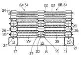
방열기(5)는 드로운 컵 타입의 열교환기이며, 연결부(4)와 평행하게 배치된 제1코어(5A) 및 제2코어(5B)를 포함한다. 제1코어(5A) 및 제2코어(5B)는 연결부(4)의 양측에 제공된다. 도22에서는, 제1코어(5A) 및 제2코어(5B)가 연결부(4)의 일측에만 도시되어 있다. 각각의 제1코어(5A) 및 제2코어(5B)는 복수 개의 평편한 방열관(22) 및 방열핀(23)을 적층하므로써 구성된다.The
방열관(22)은 두개의 프레스 가공 플레이트(24)의 외주연부를 접합하므로써 형성된 중공 구조이다. 프레스 가공 중 펀치된 연통구멍(25, 26)(도22 참조)은 길이방향 양단을 향해 개방되어 연통구멍(25, 26)을 통해 다른 적층된 방열관(22)과 연통된다. 방열관(22)은 하나의 연통구멍(25)이 개방되는 유입챔버(27), 다른 연통구멍(26)이 개방되는 유출챔버(28) 및 유입챔버(27)를 유출챔버(28)와 연통시키기 위한 냉매통로(29)를 갖는다.The
제1코어(5A) 및 제2코어(5B)는, 방열관(22)의 유입챔버(27)가 방열관(22)의 하나의 연통구멍(25) 및 연결부(4)의 제1연통개구부(20)를 통하여 연결부(4)의 제1연통챔버(18)와 연통하며, 방열관(22)의 유출챔버(28)가 방열관(22)의 다른 연통구멍(26) 및 연결부(4)의 제2연통개구부(21)를 통하여 연결부(4)의 제2연통챔버(19)와 연통되도록 구성된다.In the
방열핀(23)은 적층 방향으로 인접한 방열관(22) 사이에 형성된 공기를 송풍하기 위한 평편한 공간 내로 삽입되며, 방열관(22)의 외벽면에 접합된다.The
방열기(5)로의 송풍을 위한 냉각팬은 송풍 방향이 대채로 방열기(5)에 수직이 되도록 방열기(5)의 상부 또는 하부에 배치된다.The cooling fan for blowing to the
이하, 본 실시예에 따른 냉각장치(1)의 작동을 설명한다.Hereinafter, the operation of the
발열체(2)로부터 발생된 열에 의해 비등된 냉매는 기포로서 증기 통로(9)를 통해 상승하며, 증기 통로(9)로부터 연결부(4)의 제1연통챔버(18)를 통과하는 제1코어(5A) 및 제2코어(5B)의 방열관(22)의 유입챔버(27)로 흘러간다. 제1코어(5A) 및 제2코어(5B)에서, 방열관(22) 내로 흘러 들어온 증발냉매는, 냉매통로(29)를 통해 흐를 때, 응축잠열을 방출하여, 응축 및 액화된다. 액화되어 물방울 형태로 맺힌 냉매는 방열관(22)의 유출챔버(28) 밖으로 흘러 나가, 연결부(4)의 제2연통챔버(19) 내로 흘러 들어가고, 또한, 제2연통챔버(19)로부터 냉매탱크(3)의 응축액 통로(10)로 흘러 들어간다. 응축액 통로(10)로부터 흘러 내려온 응축액은 캡(8)에서 연통로(14)를 통과하는 증기 통로(9)로 다시 공급된다. 한편, 방열관(22)에서 증발냉매가 응축될 때 방출된 응축잠열은 방열관(22)의 벽면으로부터 방열핀(23)으로 전달되어 냉각팬에 의한 송풍 공기 속으로 방출된다.The refrigerant boiled by the heat generated from the
제5실시예에 따르면, 방열기(5)를 구성하는 제1코어(5A) 및 제2코어(5B)는 연결부(4)와 평행하게 배치된다. 그러므로, 코어(5A, 5B)를 형성하는 방열관(22)에서, 냉매통로(29)는 방열 코어의 종래의 방열관과 비하여 더 단축되게 된다. 이렇게 하여, 방열관(22)의 냉매통로(29)의 출구에서 증발냉매의 온도는 종래 방식에 비해 상승하며, 따라서 방열기(5)의 방열핀(23)의 온도는 대기와의 온도 차이가 크게 취해질 수 있도록 상승한다. 그 결과, 방열에 기여하지 않는 영역을 상당히 감소시킬 수 있으며, 그에 따라, 방열성능을 향상시킬 수 있게 된다. 다시 말하면, 방열기(5)는 종래 방식과 동일한 정도의 방열성능을 얻을 수 있으면서 소형화될 수 있다.According to the fifth embodiment, the
본 실시예에서, 유입챔버(27) 및 유출챔버(28)는 제1코어(5A) 및 제2코어(5B)의 방열관(22)의 내외측에 각각 제공된다. 그러나, 냉매탱크(3)의 증기 통로(9)의 위치 및 응축액 통로(20)의 위치는 유출챔버(28)가 방열관(22)의 내부에 제공되고 유입챔버(27)가 외부에 제공될 수 있도록 서로 변경되기도 한다.In this embodiment, the
이하, 본 발명의 제6실시예를 도23 내지 도25를 참조하여 설명한다.Hereinafter, a sixth embodiment of the present invention will be described with reference to Figs.
도23은 냉각장치의 정면도이며, 도24는 냉각장치의 측면도이며, 도25는 도23의 ⅩⅩⅤ-ⅩⅩⅤ 선을 따라 보여진 단면도이다.FIG. 23 is a front view of the cooling device, FIG. 24 is a side view of the cooling device, and FIG. 25 is a sectional view taken along the line VV-VV of FIG.
본 실시예에서, 제1코어(5A) 및 제2코어(5B)의 방열관(22)은 일체로 구성된다. 이 경우, 방열관(22)의 각 유입챔버(27)가 공통적으로 이용될 수 있으므로, 방열핀(23)이 장착되는 면적이 크게 취해질 수 있다. 그러므로, 방열성능이 더욱 향상될 수 있다.In this embodiment, the
본 실시예에서, 유입챔버(27)가 방열관(22)의 중앙부에 제공되며, 유출챔버(28)가 양측에 제공된다. 그러나, 냉매탱크(3)의 증기 통로(9)의 위치 및 응축액 통로(10)의 위치는, 유출챔버(28)가 방열관(22)의 중앙부에 제공되고 유입챔버(27)가 양측에 제공될 수 있도록 서로 변경될 수도 있다.In this embodiment, the
이하, 본 발명의 제7실시예를 설명한다.The seventh embodiment of the present invention will be described below.
본 실시예에서는, 방열기(4)를 구성하는 방열관(39)이 방열기(4)에서 액화된 응축액냉매를 냉매탱크(3)로 원활하게 되돌리도록 경사져 배치된다.In this embodiment, the
도28 도29를 참조하면, 냉매탱크(3)는, 예를 들면, 알루미늄 블록을 압출 가공하여 형성된 압출부재(7) 및 압출부재(7)의 하부 개방단을 덮는 앤드 캡(22)을 포함한다. 압출부재(7)의 내부는 수직으로 연장하는 격벽(30, 31, 32)에 의해 복수 개의 증기 통로(9), 즉, 기상 냉매통로, 응축액 통로(10), 즉 응축액 냉매통로(10), 및 비작동 통로(33)로 구획된다. 증기 통로(9)의 개방단 및 응축액 통로(10)의 개방단은 냉매탱크출구(35) 및 냉매탱크입구(36)에 각각 연결된다.Referring to FIG. 28 and FIG. 29, the
앤드 캡(22)은 압출부재(7)와 동일한 재질, 즉, 알루미늄으로 제작되며, 압출부재(7)의 비작동 통로(33), 응축액 통로(10), 및 증기 통로(9)를 서로 연통시키는 하부 연통챔버(38)를 형성하도록 압출부재(7)의 하단부에 납땜된다. 냉매를 봉입하기 위한 튜브(49)가 앤드 캡(22)에 부착되며, 상기 튜브를 통하여, 냉각장치(1)의 세정, 냉매의 공급, 및 배기 작업이 수행된다. 냉각장치(1)를 배기시킬 경우, 냉매를 그 내부에 충진시킨 후, 냉각장치를 수직으로 반전시키며, 방열기(4)를 온수 탱크(냉매의 포화 증기압이 대기압보다 높게 되는 온도로 유지된)에 잠기게 한다. 따라서, 냉매는 냉각장치(1)에서 기화되며, 공기의 비중보다 큰 비중을 갖는 냉매 증기에 의해 공기는 냉각장치(1)로부터 배출된다. 냉각장치가 배기된 후(즉, 냉각장치에서 공기가 추출된 후), 튜브(49)는 코오킹되고 용접 등에 의해 밀폐되어 냉각장치(1) 내에 냉매를 봉입하게 된다.The
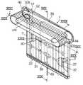
방열기(4)는 소위 드로운 컵 타입의 열교환기이다. 방열기(4)는 도30에 도시된 바와 같은 동일한 중공 형상의 복수 개의 방열관(39)을 적층하므로써 구성된다.The
방열관(39)은, 예를 들면, 도32에 도시된 알루미늄재로 된 두개의 프레스 가공 판재(40)의 주연부를 접합하므로써 형성된 중공 구조이다. 방열관(39)의 양단에는 소구경 개구부(41)가 각각 제공된 유출연통부(45) 및 유입연통부(44)가 제공된다. 방열관(39)은 그 내부 정중심부에 방열통로(42)를 형성한다. 도33에 도시된 바와 같이, 얇은 알루미늄 판재를 굽힘 가공하여 형성된 파형의 내부핀(391)(응축핀)이 냉매통로(42) 내부에 삽입된다.The
연결관(51)은 두개의 판재(50)를 접합하므로써 형성된다. 연결관(51)은 도30에 도시된 바와 같이 냉매탱크(3)의 상단부를 덮는다. 방열기(4)는 연결관(51)을 통해 냉매탱크(3)와 연통한다. 도29에 도시된 바와 같이, 연결관(51)의 내부는, 격판(52)에 의해, 냉매탱크(3)에 형성된 냉매탱크출구(35)와 연통하는 유입챔버(511) 및 냉매탱크(3)에 형성된 냉매탱크입구(36)와 연통하는 유출챔버(512)로 나누어진다. 연결관(51)용 복수 개의 내부핀(53)이 연결관(51)의 유입챔버(511)에 삽입된다.The connecting
도29, 도34, 및 도35에 도시된 바와 같이, 내부 핀(391)에는 응축액냉매를 냉매통로(42)의 하부로 떨어뜨리기 위한 복수 개의 슬릿(개구부)(392)가 제공된다. 다시 말하면, 응축액냉매가 흐르는 응축액 통로(394) 및 기상 상태의 냉매가 흐르는 복수 개의 작은 통로로 구성된 기상 냉매통로(393)가 냉매통로(42)에 형성되며, 내부핀(391)이 증발냉매를 응축하기 위하여 기상 냉매통로(393)에 제공된다. 내부핀(391)에는 응축 액화된 냉매를 응축액 통로(394) 속으로 떨어뜨리기 위한 복수 개의 슬릿이 형성된다. 각각의 작은 통로는 내부핀(391)의 바닥벽(398), 측벽(297) 및 상부벽(395), 및 프레스 가공 판재(40)의 측벽(397)에 의해 정의된다. 본 실시예에서는, 슬릿(392)은 내부핀(391)에서 냉매가 이동하는 방향에 대해 서로 다른 위치에 형성된다.29, 34, and 35, the
도31에 도시된 바와 같이, 방열관(39)은 연결관(51)의 일측에 적층되어 각각의 소구경 개구부(41)를 통해 서로 연통된다. 연결관(51) 및 방열관(39)은 연결관(51)의 판재(50)(방열관(39)의 측편에서의 판재(50))에 형성된 소구경 개구부(41) 및 인접한 방열관(39)에 형성된 소구경 개구부를 통하여 서로 연통한다. 방열관(39)은, 도29에 도시된 바와 같이, 유입연통부(44)의 높이가 유출연통부(45)보다 높게 되도록 경사지면서 연결관(51)에 부착된다. 판재(50)에는 판재(50)부분을 보강하도록 리브(50b)가 제공되어 인접한 방열관(39)에 접합된다.As shown in Fig. 31, the
이하, 제7실시예의 작동을 설명한다.The operation of the seventh embodiment will be described below.
도28에 도시된 바와 같이, IGBT 모듈로부터 발생되고 전달된 열에 의해 비등된 냉매는 기포로 증기 통로(9)를 통해 상승하며, 냉매탱크(3)의 냉매탱크출구(35)를 통하여 연결관(51)의 유입챔버로 흘러가며, 방열관(39)의 유입연통부(44)를 통하여 방열관(39)의 냉매통로(42)로 분배된다. 냉매의 흐름은 도28에서 단일선으로 단순히 지시되었다. 증발냉매가 냉매통로(42)를 통해 흐름에 따라, 증발냉매는 냉각팬(5)에 의해 송풍된 공기에 의해 낮은 온도로 냉각된 냉매통로(42)의 내부면 및 내부핀(391)의 표면에서 응축되며, 응축잠열을 방출하여 물방울 형태로 맺힌다. 응축 액화된 냉매가 각 냉매통로에서 내부핀(391)의 표면을 따라 유출연통부(45)를 향해 흐를 때, 액냉매는 유출연통부(45)로 흐르는 도중에 슬릿(392)을 통해 하부 내부핀(391)으로 떨어진다. 본 실시예에서는, 복수 개의 슬릿(392)이 형성되며, 냉매는 연속하여 물방울로 맺혀 흐르며, 각 냉매통로(42)의 바닥면에 도달하게 된다. 다시 말하면, 냉매통로(42)에서 기상 냉매통로(393)의 각기 작은 통로에서 응축 액화된 냉매는 슬릿(392)을 통해 하부 작은 통로로 흘러 응축액 통로(394)로 흘러 내려간다. 결국, 냉매는 냉매통로(42)의 바닥면을 흐르면서 각 방열관(39)의 유출연통부(45) 속으로 흐른다.As shown in FIG. 28, the refrigerant boiled by the heat generated and transferred from the IGBT module rises through the
그 후, 응축액냉매는 유출연통부(45)로부터 연결관(51)의 유출챔버로 흘러가며, 또한, 냉매탱크(3)의 냉매탱크입구(36)를 통해 응축액 통로(10)로 흘러가며, 앤드 캡(22)에 형성된 연통로(38)를 통하여 각각의 증기 통로(9)로 되돌려 진다.Thereafter, the condensate refrigerant flows from the
도34A에 도시된 바와 같이, 내부핀(391)에는 응축액냉매가 냉매통로에서 하부로 흘러 내려가는 슬릿(392)이 제공된다. 따라서, 응축 액화된 냉매가 흐르는 영역이 냉매통로(42)의 하부측에 형성되며, 냉매통로(42)의 상부측은 기상 냉매가 흐르는 영역이 될 수 있다. 그 결과, 냉매통로(42)에서 각각의 내부핀(391)에 의해 정의된 작은 통로의 바닥면이 응축액냉매로 덮여지는 것이 억제될 수 있다. 즉, 도34B에 도시된 바와 같이, 증발냉매의 열은 작은 통로의 상부벽(395) 및 측벽(396, 397)뿐만 아니라 하부벽(398)으로 효율적으로 전달될 수 있다. 그 결과, 증발냉매의 열이 전달되는 방열면적의 감소가 방지될 수 있으며, 방열성능의 저하가 방지될 수 있다.As shown in Fig. 34A, the
슬릿(392)은 냉매의 흐름방향에 대해 내부핀(392)에서 다른 위치에 형성되므로, 냉매통로(42)에서 정체하는 응축액 냉매량은 감소된다. 그 결과, 증발냉매가 효율적으로 응축될 수 있게 된다.Since the
본 발명의 제7실시예에 따르면, 다음의 효과를 얻을 수 있다.According to the seventh embodiment of the present invention, the following effects can be obtained.
소구경부의 소구경 개구부(41)가 유입연통부를 정의하는 벽에 형성되므로, 액냉매가 냉매통로(42)속으로 흐르는 것을 억제할 수가 있다. 그러므로, 응축에 의해 냉매통로(42)에서 열이 전달될 수 있으며, 방열성능의 저하가 방지될 수가 있다. 소구경 개구부를 제공하므로써, 냉매통로(42)로의 냉매의 불균일한 흐름이 방지될 수 있고, 또한 균일하게 냉매를 냉매통로(42)로 분배할 수가 있으며, 그에 의해, 방열성능의 저하가 방지될 수 있다.Since the small
방열관(39)이 연결관(51)에 대해 경사지므로, 응축액냉매는 냉매통로(42)를 통하여 유입연통부(44) 측에서 유출연통부(45)를 향해 용이하게 흐르게 된다. 그러므로, 냉매통로(42)의 바닥면에 정체하는 냉매량이 감소되며, 증발냉매가 효율적으로 응축될 수 있다. 결과적으로, 필요 냉매가 감소되며, 냉각장치의 비용이 최소화될 수 있다.Since the
압출부재(7)의 내부는 격벽(31)에 의해 복수 개의 증기 통로(9)로 분할되므로, 증기 통로(9)를 통하여 흐르는 증발냉매의 흐름은 원활하게 될 수 있다. 또한, 격벽(31)에 의해, 유효비등면적이 증가 될 수 있으며, 냉각장치의 방열성능이 향상될 수 있다. 또한, 정부압에 대한 냉매탱크(3)의 강도가 향상될 수 있으며, IGBT 모듈(2)이 부착되는 냉매탱크(3) 벽의 변형의 방지가 가능하게 된다.Since the inside of the
방열기는 각기 동일한 중공 형상을 갖는 복수 개의 방열관을 적층하고 방열관 조립체를 냉매탱크에 접합된 연결유닛에 연결하므로써 구성될 수 있으므로, 냉매탱크에 부착된 발열체의 수가 증가되어 총 발생 열량이 증가될 때, 방열기 용량은 각기 동일한 중공 형상을 갖는 추가적인 방열관을 방열관 조립체에 적층하므로써 용이하게 변경될 수가 있다. 따라서, 필요 발생 열량에 대응하는 용량을 갖는 방열기를 저렴한 비용으로 제공하는 것이 가능하게 된다.The radiator can be configured by stacking a plurality of radiator tubes each having the same hollow shape and connecting the radiator tube assembly to the connection unit joined to the refrigerant tank, so that the number of heat generating elements attached to the refrigerant tank can be increased to increase the total amount of heat generated. At this time, the heat sink capacity can be easily changed by stacking additional heat pipes each having the same hollow shape in the heat pipe assembly. Therefore, it becomes possible to provide the radiator which has the capacity | capacitance corresponding to a required heat | fever generated at low cost.
냉매탱크(3) 내부에는 냉매탱크(3)의 저단부에서 증기 통로를 응축액 통로와 연통시키는 하부 연통로(38)가 제공되므로, 냉각된 액냉매는 응축액 통로에서 증기 통로로 계속적으로 공급된다. 그러므로, 플러딩(증발냉매 및 액냉매가 유동 할 때, 상호 간섭하는 현상)이 방지될 수 있다.Since the
방열관(39)이 연결부재(51)를 통해 냉매탱크(3)에 연결되므로, 방열관(39)이 설치되는 방향 및 위치는 연결부재(51)의 형상을 변화시키므로써 적절하게 변경될 수 있다. 따라서, 냉각장치 설계 시의 자유도가 향상된다. 이렇게 하여, 냉각장치가 소형화될 수 있게 된다.Since the
방열관(39)의 바닥면은 유입연통챔버(44)에서 유출연통챔버(45)를 향해 경사지므로, 응축액냉매는 방열통로(42)를 통해 유입연통챔버에서 유출연통챔버를 향해 원활하게 흐를 수 있게 된다. 결과적으로, 방열통로(42)의 바닥면에 정체하는 응축액 냉매량은 감소되며, 증발냉매는 효율적으로 응축될 수 있다.Since the bottom surface of the
냉매탱크(3)가 압출부재(7)에 의해 구성되므로, IGBT 모듈 수의 변화에 용이하게 대응할 수가 있다. 따라서, 생산성이 향상된다.Since the
압출부재와 일체로 형성된 격벽이 제공되어 냉매챔버의 내부를 분할하므로, 증발 통로(9) 및 응축액 통로(10)가 용이하게 형성될 수 있다.Since the partition wall formed integrally with the extrusion member is provided to divide the inside of the refrigerant chamber, the
복수 개의 증기 통로(9)가 압출부재의 격벽(31)의 상단부를 절삭 제거하므로써 간단하게 탱크출구(35)와 연통될 수 있으므로, 냉매의 순환은 어떤 별도의 부품의 사용하지 않고도 저렴한 비용으로 조절될 수가 있다.Since the plurality of
증기 통로 및 응축액 통로가 압출부재의 격벽 하단부를 절삭 제거하고 압출부재의 하단부에 밀폐부재를 접합하므로써 냉매챔버의 하부에서 연통될 수 있다. 그러므로, 밀폐부재는 단순한 형상(예를 들면, 단순한 평판재)일 수 있으며, 그의 재조가 용이하게 된다.The vapor passage and the condensate passage can be communicated at the bottom of the refrigerant chamber by cutting away the bottom end of the partition wall of the extrusion member and joining the sealing member to the bottom end of the extrusion member. Therefore, the sealing member may be of a simple shape (for example, a simple plate material), and its fabrication is easy.
복수 개의 발열체를 냉각하기 위한 냉각장치가 구성될 경우, 각각의 발열체에 대해 복수 개의 냉매챔버가 냉매탱크 내에 형성될 수 있다. 냉매챔버를 서로 연통시키므로써, 냉매가 전체의 냉매탱크를 통해 균일하게 순환할 수 있으며, 냉매탱크에서 냉매의 불균일한 분배로 인한 방열성능의 저하가 방지될 수 있다.When a cooling device for cooling the plurality of heating elements is configured, a plurality of refrigerant chambers may be formed in the refrigerant tank for each of the heating elements. By communicating the refrigerant chambers with each other, the refrigerant can be circulated uniformly through the entire refrigerant tank, and the deterioration of heat dissipation performance due to uneven distribution of the refrigerant in the refrigerant tank can be prevented.
냉매탱크를 평편한 형상으로 형성하므로써, 그 내부에서 사용된 냉매량이 감소될 수 있다. 그러므로, 고가의 플루오르카본 타입 냉매가 사용될 지라도, 그 비용은 최소화될 수 있다.By forming the coolant tank in a flat shape, the amount of coolant used therein can be reduced. Therefore, even if an expensive fluorocarbon type refrigerant is used, the cost can be minimized.
증기 통로 및 응축액 통로가 냉매챔버 내에 배치된 냉매흐름제어판에 의해 형성될 수도 있다. 이 경우, 냉매흐름제어판을 냉매챔버의 내부면에 접촉한 상태로 배치하므로써, 플러딩 방지 효과에 더하여, 냉매챔버의 강성이 향상될 수 있으며, 냉매챔버의 방열면적이 방열성능이 향상될 수 있도록 증가될 수 있다.The vapor passage and the condensate passage may be formed by a refrigerant flow control plate disposed in the refrigerant chamber. In this case, by arranging the coolant flow control plate in contact with the inner surface of the coolant chamber, in addition to the effect of preventing flooding, the rigidity of the coolant chamber can be improved, and the heat dissipation area of the coolant chamber is increased to improve heat dissipation performance. Can be.
냉매탱크뿐만이 아니라 방열기가 냉매탱크와 일체로 압출 가공하므로써 형성된 압출부재를 사용하여 구성될 수도 있다. 이렇게 하여, 방열기 비용의 감소와 방열기 및 냉매탱크를 조립하기 위한 작업을 줄일 수 있으며, 냉각장치의 총비용이 감소될 수 있다.In addition to the refrigerant tank, the radiator may be configured by using an extrusion member formed by extruding integrally with the refrigerant tank. In this way, the cost of the radiator can be reduced and the work for assembling the radiator and the refrigerant tank can be reduced, and the total cost of the cooling device can be reduced.
방열기(4)는 접합부를 갖는 복수 개의 판상부재에 의해 구성되고 판상부재의 접합부를 접합하므로써 형성된다. 접합부는 판상부재를 굽힘 가공하므로서 형성되므로, 방열기의 형성이 용이하게 된다.The
슬릿(392)을 통하여, 응축액냉매가 냉매통로(42)의 하부로 떨어진다. 응축 액화된 냉매가 흐르는 영역이 냉매통로(42)의 하측에 형성되며, 냉매통로(42)의 상측은 기상 냉매가 흐르는 영역일 수 있다. 그러므로, 냉매통로(42)에서 냉매의 흐름이 방해되는 것이 방지될 수 있다. 그 결과, 기상 냉매통로(393)가 통과할 수 있는 최소 유동로 단면적의 감소를 방지하며, 또한 방열성능의 저하를 방지 할 수 있게 된다.Through the
도34에 도시된 바와 같이, 슬릿(392)은 내부핀(391)에서 서로 다른 위치에 형성된다. 그러나, 슬릿(392)은, 도36에 도시된 바와 같이, 대체로 동일한 위치에 형성될 수도 있으며, 이렇게 하여, 슬릿(392)의 형성이 용이하게 된다.As shown in Figure 34, the
또한, 도37A, 도37B, 도37C에 도시된 바와 같이, 내부핀(391)은 서로로부터 전위된(방향이 바뀐) 두개의 파형 부재에 의해 구성될 수도 있으며, 슬릿(392)이 전위된 두개의 파형 부재 사이에 형성될 수도 있다.Also, as shown in Figs. 37A, 37B, and 37C, the
본 발명이, 첨부된 도면을 참조하여, 바람직한 실시예 관련하여 충분히 설명되었을지라도, 여러 가지 변경 및 변형이 해당 분야에서 통상의 기술을 가진 자에게 명백할 것이다. 상기 변경 및 변형은 청구범위에서 한정된 본 발명의 범주에 포함되는 것으로 이해되어야 한다.Although the present invention has been described fully with reference to the accompanying drawings, various changes and modifications will be apparent to those of ordinary skill in the art. It is to be understood that such changes and modifications are intended to be included within the scope of the invention as defined in the claims.
상기와 같이 구성된 본 발명에 따르면, 냉매통로에서 응축열전달을 위한 유효방열면적이 증대하므로, 방열코어의 대형화할 필요 없이 방열성능을 향상시키는 효과가 있으며, 방열기의 제작비용의 절감과 필요 냉매량의 감소에 따른 비용절감등의 경제적 효과가 있다.According to the present invention configured as described above, since the effective heat dissipation area for condensation heat transfer in the refrigerant passage increases, there is an effect of improving the heat dissipation performance without having to increase the size of the heat dissipation core, reducing the production cost of the heat sink and the amount of refrigerant required There is an economic effect such as cost reduction.
Claims (34)
Translated fromKoreanApplications Claiming Priority (18)
| Application Number | Priority Date | Filing Date | Title |
|---|---|---|---|
| JP5736096 | 1996-03-14 | ||
| JP5735996 | 1996-03-14 | ||
| JP57,360/1996 | 1996-03-14 | ||
| JP57360/1996 | 1996-03-14 | ||
| JP57,359/1996 | 1996-03-14 | ||
| JP57359/1996 | 1996-03-14 | ||
| JP198,644/1996 | 1996-07-29 | ||
| JP19864496 | 1996-07-29 | ||
| JP198644/1996 | 1996-07-29 | ||
| JP218184/1996 | 1996-08-20 | ||
| JP218,184/1996 | 1996-08-20 | ||
| JP8218184AJPH1065077A (en) | 1996-08-20 | 1996-08-20 | Boiling cooling device |
| JP334094/1996 | 1996-12-13 | ||
| JP334,094/1996 | 1996-12-13 | ||
| JP33409496AJP3501911B2 (en) | 1996-03-14 | 1996-12-13 | Boiling cooling device |
| JP6,255/1997 | 1997-01-17 | ||
| JP6255/1997 | 1997-01-17 | ||
| JP9006255AJPH1098142A (en) | 1996-03-14 | 1997-01-17 | Boiling cooler |
Publications (2)
| Publication Number | Publication Date |
|---|---|
| KR19980069709A KR19980069709A (en) | 1998-10-26 |
| KR100260676B1true KR100260676B1 (en) | 2000-07-01 |
Family
ID=27547972
Family Applications (1)
| Application Number | Title | Priority Date | Filing Date |
|---|---|---|---|
| KR1019970008173AExpired - Fee RelatedKR100260676B1 (en) | 1996-03-14 | 1997-03-12 | Cooling system using boiling and condensation refrigerant |
Country Status (4)
| Country | Link |
|---|---|
| US (2) | US6527045B1 (en) |
| KR (1) | KR100260676B1 (en) |
| DE (1) | DE19709934B4 (en) |
| FR (1) | FR2746492B1 (en) |
Families Citing this family (37)
| Publication number | Priority date | Publication date | Assignee | Title |
|---|---|---|---|---|
| US6808015B2 (en)* | 2000-03-24 | 2004-10-26 | Denso Corporation | Boiling cooler for cooling heating element by heat transfer with boiling |
| US6856037B2 (en)* | 2001-11-26 | 2005-02-15 | Sony Corporation | Method and apparatus for converting dissipated heat to work energy |
| JP2003214750A (en)* | 2002-01-23 | 2003-07-30 | Twinbird Corp | Thermosiphon |
| TW531634B (en)* | 2002-03-08 | 2003-05-11 | Ching-Feng Wang | Counter flow type heat exchanger with integrally formed fin and tube |
| JP2005122503A (en)* | 2003-10-17 | 2005-05-12 | Hitachi Ltd | Cooling device and electronic device incorporating the same |
| JP4382445B2 (en)* | 2003-11-18 | 2009-12-16 | トヨタ自動車株式会社 | Cooling structure for electrical equipment |
| TWM267825U (en)* | 2004-11-03 | 2005-06-11 | Forward Electronics Co Ltd | Improved heat sink structure of liquid-cooling type heat sink device |
| US8683690B2 (en)* | 2006-01-19 | 2014-04-01 | Modine Manufacturing Company | Flat tube, flat tube heat exchanger, and method of manufacturing same |
| US20090019696A1 (en)* | 2006-01-19 | 2009-01-22 | Werner Zobel | Flat tube, flat tube heat exchanger, and method of manufacturing same |
| US8191258B2 (en)* | 2006-01-19 | 2012-06-05 | Modine Manufacturing Company | Flat tube, flat tube heat exchanger, and method of manufacturing same |
| US8091621B2 (en)* | 2006-01-19 | 2012-01-10 | Modine Manufacturing Company | Flat tube, flat tube heat exchanger, and method of manufacturing same |
| WO2007084996A2 (en)* | 2006-01-19 | 2007-07-26 | Modine Manufacturing Company | Flat tube, flat tube heat exchanger, and method of manufacturing same |
| US7921559B2 (en)* | 2006-01-19 | 2011-04-12 | Modine Manufacturing Company | Flat tube, flat tube heat exchanger, and method of manufacturing same |
| US8281489B2 (en)* | 2006-01-19 | 2012-10-09 | Modine Manufacturing Company | Flat tube, flat tube heat exchanger, and method of manufacturing same |
| US20090014165A1 (en)* | 2006-01-19 | 2009-01-15 | Werner Zobel | Flat tube, flat tube heat exchanger, and method of manufacturing same |
| US8438728B2 (en)* | 2006-01-19 | 2013-05-14 | Modine Manufacturing Company | Flat tube, flat tube heat exchanger, and method of manufacturing same |
| DE102006029378B4 (en)* | 2006-06-27 | 2014-02-13 | Modine Manufacturing Co. | Flat tube for heat exchangers and manufacturing process |
| US8434227B2 (en) | 2006-01-19 | 2013-05-07 | Modine Manufacturing Company | Method of forming heat exchanger tubes |
| WO2008064199A1 (en)* | 2006-11-22 | 2008-05-29 | Johnson Controls Technology Company | Multichannel evaporator with flow separating manifold |
| DE102007004993A1 (en) | 2007-02-01 | 2008-08-07 | Modine Manufacturing Co., Racine | Production process for flat tubes and roller mill |
| EP2119994A1 (en)* | 2008-05-14 | 2009-11-18 | Abb Research Ltd. | Evaporator for a cooling circuit |
| JP5210997B2 (en)* | 2009-08-28 | 2013-06-12 | 株式会社日立製作所 | COOLING SYSTEM AND ELECTRONIC DEVICE USING THE SAME |
| DE102010023384B4 (en) | 2010-06-10 | 2014-08-28 | Modine Manufacturing Co. | Manufacturing process, in particular for pipes and tear-off device |
| JP5401419B2 (en)* | 2010-08-31 | 2014-01-29 | 株式会社日立製作所 | Railway vehicle power converter |
| US9557115B2 (en)* | 2010-10-28 | 2017-01-31 | General Electric Technology Gmbh | Orifice plate for controlling solids flow, methods of use thereof and articles comprising the same |
| US9617087B2 (en) | 2010-10-28 | 2017-04-11 | General Electric Technology Gmbh | Control valve and control valve system for controlling solids flow, methods of manufacture thereof and articles comprising the same |
| CN105992487A (en)* | 2015-01-28 | 2016-10-05 | 讯凯国际股份有限公司 | Radiator module and siphon type radiator thereof |
| US10201119B2 (en)* | 2015-06-02 | 2019-02-05 | Hamilton Sundstrand Corporation | System and method of alternate cooling of a liquid cooled motor controller |
| CN108029221B (en)* | 2015-09-14 | 2019-11-29 | 三菱电机株式会社 | Coolers, power conversion devices and cooling systems |
| US10483727B2 (en) | 2017-09-01 | 2019-11-19 | Eaton Intelligent Power Limited | Cooling system for tanks |
| JP2019170075A (en)* | 2018-03-23 | 2019-10-03 | 日本電産トーソク株式会社 | Inverter device |
| JP2019170064A (en)* | 2018-03-23 | 2019-10-03 | 日本電産トーソク株式会社 | Inverter device |
| KR102575151B1 (en)* | 2018-07-17 | 2023-09-06 | 현대자동차주식회사 | Cooling module for parallel type power module of inverter |
| WO2022184244A1 (en)* | 2021-03-03 | 2022-09-09 | Huawei Technologies Co., Ltd. | Heat sink comprising container for accommodating cooling fluid |
| CN114302608B (en) | 2021-03-31 | 2024-01-30 | 华为数字能源技术有限公司 | Heat exchanger, cabinet and communication base station |
| CN116951899A (en)* | 2023-08-03 | 2023-10-27 | 淮北金科合成材料有限公司 | Chemical raw material cooling device |
| CN119803133B (en)* | 2025-03-13 | 2025-05-30 | 中国计量大学 | Modular integrated multi-layer independent parallel driven capillary wick microchannel heat exchanger |
Family Cites Families (44)
| Publication number | Priority date | Publication date | Assignee | Title |
|---|---|---|---|---|
| JPS51145044A (en) | 1975-06-09 | 1976-12-13 | Mitsubishi Electric Corp | Boiling type refrigeration system |
| JPS53109249A (en) | 1977-03-04 | 1978-09-22 | Hitachi Ltd | Thermosyphon tube assembly |
| JPS5414169A (en) | 1977-07-04 | 1979-02-02 | Mitsubishi Electric Corp | Boiling and cooling unit |
| JPS54128286A (en)* | 1978-03-29 | 1979-10-04 | Hitachi Ltd | Boiling cooler |
| JPS54147552A (en)* | 1978-05-10 | 1979-11-17 | Toshiba Corp | Oil-filled electric apparatus |
| JPS54158871A (en) | 1978-06-06 | 1979-12-15 | Mitsubishi Electric Corp | Boiling-cooling unit |
| JPS5614757A (en) | 1979-07-17 | 1981-02-13 | Fujitsu Ltd | Frequency modulation system |
| JPS5651848A (en)* | 1979-10-05 | 1981-05-09 | Hitachi Ltd | Condenser for boiling type cooling device |
| JPS56147457A (en)* | 1980-04-16 | 1981-11-16 | Mitsubishi Electric Corp | Vapor cooling type semiconductor device |
| JPS56149588A (en) | 1980-04-18 | 1981-11-19 | Mitsubishi Electric Corp | Condenser for boiling type cooler |
| JPH062830B2 (en) | 1983-04-13 | 1994-01-12 | 東洋紡績株式会社 | Highly adhesive composite polyester molding |
| JPS60194289A (en) | 1984-03-13 | 1985-10-02 | Ishikawajima Harima Heavy Ind Co Ltd | Assembling technique for heat pipe type heat exchanger |
| JPS61141442A (en) | 1984-12-14 | 1986-06-28 | Fuji Photo Film Co Ltd | Photosoluble composition |
| JPS61234059A (en) | 1985-04-10 | 1986-10-18 | Hitachi Ltd | Vapor cooling device for semiconductor element |
| JPS62162847A (en) | 1986-01-10 | 1987-07-18 | Toto Ltd | Gas instantaneous type hot water supplier |
| DE3544185A1 (en)* | 1985-12-13 | 1987-06-19 | Fuji Electric Co Ltd | Cooling system with a boiling coolant |
| JP2646580B2 (en) | 1986-12-11 | 1997-08-27 | 株式会社デンソー | Refrigerant evaporator |
| GB8704411D0 (en) | 1987-02-25 | 1987-04-01 | Gen Electric Co Plc | Cabinet |
| JPH01263491A (en) | 1988-04-14 | 1989-10-19 | Asahi Glass Co Ltd | Heat exchanger using heat pipe |
| JP2636337B2 (en) | 1988-06-02 | 1997-07-30 | 株式会社デンソー | Refrigerant evaporator |
| JPH023320A (en) | 1988-06-17 | 1990-01-08 | Canon Inc | inkjet recording device |
| JPH0293270A (en) | 1988-09-29 | 1990-04-04 | Nec Corp | Cooling mechanism by using heat pipe |
| US4944344A (en)* | 1988-10-31 | 1990-07-31 | Sundstrand Corporation | Hermetically sealed modular electronic cold plate utilizing reflux cooling |
| JPH02233993A (en) | 1989-03-07 | 1990-09-17 | Furukawa Electric Co Ltd:The | Airtight enclosure cooler |
| JPH02251187A (en) | 1989-03-24 | 1990-10-08 | Okuma Mach Works Ltd | Co2 gas laser oscillator |
| US5076351A (en)* | 1989-07-19 | 1991-12-31 | Showa Aluminum Corporation | Heat pipe |
| JP2859927B2 (en)* | 1990-05-16 | 1999-02-24 | 株式会社東芝 | Cooling device and temperature control device |
| JP2909602B2 (en) | 1990-09-14 | 1999-06-23 | 昭和アルミニウム株式会社 | heat pipe |
| JP3042541B2 (en) | 1990-11-05 | 2000-05-15 | 古河電気工業株式会社 | Heat pipe type cooler |
| JPH0492166U (en)* | 1990-12-04 | 1992-08-11 | ||
| JPH04267593A (en) | 1991-02-22 | 1992-09-24 | Furukawa Electric Co Ltd:The | Heat pipe type cooling structure for casing |
| JP2585479B2 (en) | 1991-04-23 | 1997-02-26 | 株式会社日立製作所 | Boiling cooling device |
| JPH0560476A (en) | 1991-09-04 | 1993-03-09 | Furukawa Electric Co Ltd:The | Heat pipe mounting structure |
| JP2695076B2 (en) | 1991-09-26 | 1997-12-24 | 日本碍子株式会社 | Method for manufacturing beryllium window for X-ray source |
| JPH05102687A (en) | 1991-10-04 | 1993-04-23 | Furukawa Electric Co Ltd:The | Cooler for housing |
| JPH05141811A (en) | 1991-11-22 | 1993-06-08 | Nippondenso Co Ltd | Heat exchanger |
| JPH0612554A (en) | 1992-06-26 | 1994-01-21 | Furukawa Electric Co Ltd:The | Cigarette vending machine |
| JP3456713B2 (en) | 1992-07-30 | 2003-10-14 | 株式会社東芝 | Semiconductor element cooling unit |
| JPH0730023A (en) | 1993-07-13 | 1995-01-31 | Toshiba Corp | Semiconductor element cooling device |
| JP3351034B2 (en) | 1993-07-27 | 2002-11-25 | 栗田工業株式会社 | Method and apparatus for treating wastewater containing organic solids |
| JP3337789B2 (en) | 1993-10-15 | 2002-10-21 | 古河電気工業株式会社 | Heat pipe type cooler |
| JP3525498B2 (en)* | 1994-07-13 | 2004-05-10 | 株式会社デンソー | Boiling cooling device |
| JPH08321570A (en)* | 1995-03-17 | 1996-12-03 | Nippondenso Co Ltd | Boiling cooler |
| FR2746177B1 (en)* | 1996-03-14 | 2000-04-07 | COOLING DEVICE USING A BOILING REFRIGERANT AND CONDENSING |
- 1997
- 1997-03-11DEDE19709934Apatent/DE19709934B4/ennot_activeExpired - Lifetime
- 1997-03-12KRKR1019970008173Apatent/KR100260676B1/ennot_activeExpired - Fee Related
- 1997-03-14USUS08/818,731patent/US6527045B1/ennot_activeExpired - Lifetime
- 1997-03-14FRFR9703071Apatent/FR2746492B1/ennot_activeExpired - Fee Related
- 2002
- 2002-09-09USUS10/237,753patent/US7004239B2/ennot_activeExpired - Fee Related
Also Published As
| Publication number | Publication date |
|---|---|
| KR19980069709A (en) | 1998-10-26 |
| US20030019612A1 (en) | 2003-01-30 |
| US6527045B1 (en) | 2003-03-04 |
| DE19709934B4 (en) | 2008-04-17 |
| FR2746492B1 (en) | 2000-05-12 |
| DE19709934A1 (en) | 1997-10-30 |
| US7004239B2 (en) | 2006-02-28 |
| FR2746492A1 (en) | 1997-09-26 |
Similar Documents
| Publication | Publication Date | Title |
|---|---|---|
| KR100260676B1 (en) | Cooling system using boiling and condensation refrigerant | |
| US6357517B1 (en) | Cooling apparatus boiling and condensing refrigerant | |
| US6073683A (en) | Cooling apparatus using boiling and condensing refrigerant and method for manufacturing the same | |
| US4941530A (en) | Enhanced air fin cooling arrangement for a hermetically sealed modular electronic cold plate utilizing reflux cooling | |
| US6005772A (en) | Cooling apparatus for high-temperature medium by boiling and condensing refrigerant | |
| US6076596A (en) | Cooling apparatus for high-temperature medium by boiling and condensing refrigerant | |
| US6749013B2 (en) | Heat sink | |
| JPH08236669A (en) | Boiling cooler | |
| JP3608272B2 (en) | Boiling cooling device and manufacturing method thereof | |
| US6279649B1 (en) | Cooling apparatus using boiling and condensing refrigerant | |
| JP3924674B2 (en) | Boiling cooler for heating element | |
| JPH1098142A (en) | Boiling cooler | |
| JP7299441B1 (en) | boiling cooler | |
| KR20180109668A (en) | heat exchanger for cooling electric element | |
| JPH0923081A (en) | Boiling cooling equipment | |
| US6102109A (en) | Cooling device boiling and condensing refrigerant | |
| JP3511777B2 (en) | Boiling cooling device | |
| JP3501911B2 (en) | Boiling cooling device | |
| JP3810119B2 (en) | Boiling cooler | |
| TWI897224B (en) | Immersion cooling device | |
| JP3608286B2 (en) | Boiling cooler | |
| US11659687B2 (en) | Stack-type vertical heat dissipation device | |
| JP3494196B2 (en) | Boiling cooling device | |
| JPH1050909A (en) | Boiling cooler | |
| JP2000111225A (en) | Boiling cooling system |
Legal Events
| Date | Code | Title | Description |
|---|---|---|---|
| PA0109 | Patent application | St.27 status event code:A-0-1-A10-A12-nap-PA0109 | |
| R17-X000 | Change to representative recorded | St.27 status event code:A-3-3-R10-R17-oth-X000 | |
| A201 | Request for examination | ||
| PA0201 | Request for examination | St.27 status event code:A-1-2-D10-D11-exm-PA0201 | |
| PG1501 | Laying open of application | St.27 status event code:A-1-1-Q10-Q12-nap-PG1501 | |
| R18-X000 | Changes to party contact information recorded | St.27 status event code:A-3-3-R10-R18-oth-X000 | |
| R18-X000 | Changes to party contact information recorded | St.27 status event code:A-3-3-R10-R18-oth-X000 | |
| E701 | Decision to grant or registration of patent right | ||
| PE0701 | Decision of registration | St.27 status event code:A-1-2-D10-D22-exm-PE0701 | |
| GRNT | Written decision to grant | ||
| PR0701 | Registration of establishment | St.27 status event code:A-2-4-F10-F11-exm-PR0701 | |
| PR1002 | Payment of registration fee | St.27 status event code:A-2-2-U10-U11-oth-PR1002 Fee payment year number:1 | |
| PG1601 | Publication of registration | St.27 status event code:A-4-4-Q10-Q13-nap-PG1601 | |
| PR1001 | Payment of annual fee | St.27 status event code:A-4-4-U10-U11-oth-PR1001 Fee payment year number:4 | |
| PR1001 | Payment of annual fee | St.27 status event code:A-4-4-U10-U11-oth-PR1001 Fee payment year number:5 | |
| PR1001 | Payment of annual fee | St.27 status event code:A-4-4-U10-U11-oth-PR1001 Fee payment year number:6 | |
| PR1001 | Payment of annual fee | St.27 status event code:A-4-4-U10-U11-oth-PR1001 Fee payment year number:7 | |
| PR1001 | Payment of annual fee | St.27 status event code:A-4-4-U10-U11-oth-PR1001 Fee payment year number:8 | |
| PR1001 | Payment of annual fee | St.27 status event code:A-4-4-U10-U11-oth-PR1001 Fee payment year number:9 | |
| PR1001 | Payment of annual fee | St.27 status event code:A-4-4-U10-U11-oth-PR1001 Fee payment year number:10 | |
| PR1001 | Payment of annual fee | St.27 status event code:A-4-4-U10-U11-oth-PR1001 Fee payment year number:11 | |
| PR1001 | Payment of annual fee | St.27 status event code:A-4-4-U10-U11-oth-PR1001 Fee payment year number:12 | |
| FPAY | Annual fee payment | Payment date:20120322 Year of fee payment:13 | |
| PR1001 | Payment of annual fee | St.27 status event code:A-4-4-U10-U11-oth-PR1001 Fee payment year number:13 | |
| LAPS | Lapse due to unpaid annual fee | ||
| PC1903 | Unpaid annual fee | St.27 status event code:A-4-4-U10-U13-oth-PC1903 Not in force date:20130412 Payment event data comment text:Termination Category : DEFAULT_OF_REGISTRATION_FEE | |
| PC1903 | Unpaid annual fee | St.27 status event code:N-4-6-H10-H13-oth-PC1903 Ip right cessation event data comment text:Termination Category : DEFAULT_OF_REGISTRATION_FEE Not in force date:20130412 |