KR100257903B1 - Plasma etching apparatus capable of in-situ monitoring, its in-situ monitoring method and in-situ cleaning method for removing residues in plasma etching chamber - Google Patents
Plasma etching apparatus capable of in-situ monitoring, its in-situ monitoring method and in-situ cleaning method for removing residues in plasma etching chamberDownload PDFInfo
- Publication number
- KR100257903B1 KR100257903B1KR1019970079194AKR19970079194AKR100257903B1KR 100257903 B1KR100257903 B1KR 100257903B1KR 1019970079194 AKR1019970079194 AKR 1019970079194AKR 19970079194 AKR19970079194 AKR 19970079194AKR 100257903 B1KR100257903 B1KR 100257903B1
- Authority
- KR
- South Korea
- Prior art keywords
- gas
- etching
- chamber
- situ
- etching chamber
- Prior art date
- Legal status (The legal status is an assumption and is not a legal conclusion. Google has not performed a legal analysis and makes no representation as to the accuracy of the status listed.)
- Expired - Fee Related
Links
Images


Classifications
- H—ELECTRICITY
- H01—ELECTRIC ELEMENTS
- H01L—SEMICONDUCTOR DEVICES NOT COVERED BY CLASS H10
- H01L21/00—Processes or apparatus adapted for the manufacture or treatment of semiconductor or solid state devices or of parts thereof
- H01L21/02—Manufacture or treatment of semiconductor devices or of parts thereof
- H01L21/04—Manufacture or treatment of semiconductor devices or of parts thereof the devices having potential barriers, e.g. a PN junction, depletion layer or carrier concentration layer
- H01L21/18—Manufacture or treatment of semiconductor devices or of parts thereof the devices having potential barriers, e.g. a PN junction, depletion layer or carrier concentration layer the devices having semiconductor bodies comprising elements of Group IV of the Periodic Table or AIIIBV compounds with or without impurities, e.g. doping materials
- H01L21/30—Treatment of semiconductor bodies using processes or apparatus not provided for in groups H01L21/20 - H01L21/26
- H01L21/302—Treatment of semiconductor bodies using processes or apparatus not provided for in groups H01L21/20 - H01L21/26 to change their surface-physical characteristics or shape, e.g. etching, polishing, cutting
- H01L21/306—Chemical or electrical treatment, e.g. electrolytic etching
- H01L21/3065—Plasma etching; Reactive-ion etching
- H—ELECTRICITY
- H01—ELECTRIC ELEMENTS
- H01J—ELECTRIC DISCHARGE TUBES OR DISCHARGE LAMPS
- H01J37/00—Discharge tubes with provision for introducing objects or material to be exposed to the discharge, e.g. for the purpose of examination or processing thereof
- H01J37/32—Gas-filled discharge tubes
- H01J37/32917—Plasma diagnostics
- H01J37/32935—Monitoring and controlling tubes by information coming from the object and/or discharge
- H01J37/32963—End-point detection
- Y—GENERAL TAGGING OF NEW TECHNOLOGICAL DEVELOPMENTS; GENERAL TAGGING OF CROSS-SECTIONAL TECHNOLOGIES SPANNING OVER SEVERAL SECTIONS OF THE IPC; TECHNICAL SUBJECTS COVERED BY FORMER USPC CROSS-REFERENCE ART COLLECTIONS [XRACs] AND DIGESTS
- Y10—TECHNICAL SUBJECTS COVERED BY FORMER USPC
- Y10S—TECHNICAL SUBJECTS COVERED BY FORMER USPC CROSS-REFERENCE ART COLLECTIONS [XRACs] AND DIGESTS
- Y10S438/00—Semiconductor device manufacturing: process
- Y10S438/905—Cleaning of reaction chamber
Landscapes
- Engineering & Computer Science (AREA)
- Physics & Mathematics (AREA)
- Plasma & Fusion (AREA)
- Chemical & Material Sciences (AREA)
- Analytical Chemistry (AREA)
- General Physics & Mathematics (AREA)
- Condensed Matter Physics & Semiconductors (AREA)
- Manufacturing & Machinery (AREA)
- Computer Hardware Design (AREA)
- Microelectronics & Electronic Packaging (AREA)
- Power Engineering (AREA)
- Drying Of Semiconductors (AREA)
- Plasma Technology (AREA)
- ing And Chemical Polishing (AREA)
Abstract
Description
Translated fromKorean본 발명은 질량분석기를 내장한 RGA-QMS(Residual Gas Analyzer - Quadrupole Mass Spectrometer)을 사용하여 인시튜 모니터링가능한 플라즈마 식각장치에 관한 것이다. 또한 질량분석기를 내장한 RGA-QMS를 사용하여 플라즈마 식각챔버에서 수행되는 폴리실리콘 식각공정과 식각챔버 내의 세정공정을 인시튜(In-situ)로 모니터링하는 방법에 관한 것이다. 또한 상기 RGA-QMS를 사용하여 식각챔버 내의 가스 반응메카니즘을 모니터링하여 세정공정을 최적화시킨 플라즈마 식각챔버내의 잔류물 제거를 위한 인시튜 세정방법에 관한 것이다.The present invention relates to an in-situ monitorable plasma etching apparatus using a RGA-QMS (Residual Gas Analyzer-Quadrupole Mass Spectrometer) with a mass spectrometer. In addition, the present invention relates to a method of monitoring in-situ a polysilicon etching process performed in a plasma etching chamber and a cleaning process in the etching chamber using a RGA-QMS having a mass spectrometer. The present invention also relates to an in-situ cleaning method for removing residue in the plasma etching chamber by optimizing the cleaning process by monitoring the gas reaction mechanism in the etching chamber using the RGA-QMS.
반도체소자 제조공정은 일반적으로 특정의 조건이 형성된 공정챔버 내에서 수행되며, 특히 플라즈마 식각, 플라즈마 CVD(PECVD) 공정에서는 많은 반응부산물이 생성되며, 이들은 사용되는 가스나 포토레지스트 등과 반응하여 고분자물질(Polymer)를 생성하게 된다. 플라즈마 공정에서 발생된 이러한 반응부산물들은 웨이퍼 표면이나 공정챔버의 내벽에도 부착되기 때문에 공정 파라미터의 변동 및 파티클 발생을 초래하게 된다. 이들은 반도체 제조공정 수행중 웨이퍼의 디펙트요인이 되어 수율저하를 초래한다.The semiconductor device manufacturing process is generally performed in a process chamber in which specific conditions are formed. In particular, in plasma etching and plasma CVD (PECVD) processes, many reaction by-products are generated, and these react with a gas or photoresist used to react with a polymer material ( Polymer). These reaction by-products generated in the plasma process also adhere to the wafer surface or the inner wall of the process chamber, resulting in variation of process parameters and particle generation. These are defects of the wafer during the semiconductor manufacturing process, resulting in yield reduction.
이러한 디펙트요인의 감소를 위해 일정시간 동안 공정챔버의 반복된 피엠(Preventive Maintenance;PM)을 수행하게 되나 설비의 운휴시간은 반도체장치의 생산성을 저하시키는 요인으로 작용한다.In order to reduce the defect factor, repeated maintenance (PM) of the process chamber is performed for a predetermined time, but the downtime of the equipment acts as a factor that lowers the productivity of the semiconductor device.
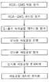
종래의 일반적인 공정챔버의 피엠과정을 도1에 도시하였다. 상기 피엠과정을 살펴보면, 먼저 반도체 웨이퍼에 대한 특정의 공정을 수행한 후 시스템의 전력을 오프하여 시스템 가동중지를 하고 시스템을 냉각시킨다. 공정챔버가 충분히 냉각되면 공정챔버 내의 부품들을 차례로 헤체 제거하며, 이어서 제거된 각 부품들을 습식식각하여 플라즈마에 의한 반응부산물들을 세정시킨다. 상기 습식식각은 공정챔버내의 폴리실리콘막이나 실리콘나이트라이드막을 제거하기 위하여 통상 불화수소(HF) 계통의 화학약품을 사용한다. 이어서 제거된 부품들을 공정챔버 내에 조립한 후, 진공펌프를 가동하여 공정챔버가 소정의 압력이 유지되도록 펌핑을 수행하며, 테스트할 웨이퍼를 공정챔버 내로 로딩한 후 소정의 에이징(aging)을 수행한 후 파티클 측정을 하는 등의 공정챔버 내에서 실제 공정을 수행할 수 있는 조건이 구비될 수 있는 지 여부를 판단하는 공정 보증(Process Recertification)을 실시한다.1 shows a conventional PM process of a general process chamber. Referring to the PM process, first, after performing a specific process for the semiconductor wafer, the system is turned off to shut down the system and cool the system. When the process chamber is sufficiently cooled, the components in the process chamber are successively removed, followed by wet etching of the removed components to clean the reaction byproducts by plasma. The wet etching typically uses a hydrogen fluoride (HF) -based chemical to remove the polysilicon film or silicon nitride film in the process chamber. Subsequently, the removed parts are assembled into the process chamber, and the vacuum chamber is operated to pump the process chamber to maintain a predetermined pressure. The wafer to be tested is loaded into the process chamber and then subjected to a predetermined aging process. Process Recertification is performed to determine whether conditions for performing the actual process can be provided in the process chamber such as measuring particles afterwards.
그러나 이와 같은 피엠방법은 그 비용 및 노동력의 소모가 클 뿐만아니라 소요시간도 24시간 이상이 걸리는 등의 문제점이 있다. 이러한 문제점을 극복하기 위하여 상기 습식식각을 수행하는 대신에 NF3,CF4가스를 이용한 플라즈마식각을 하거나, 열적 스트레스에 의해 챔버내에 형성된 막을 제거하는 열적쇼크기술(Thermal Shock Technology)을 사용하기도 하였으며, ClF3, BrF5가스를 사용하여 건식식각을 수행하기도 하였다.However, such a method of PM has a problem such that the cost and labor consumption are not only large but the time required also takes 24 hours or more. In order to overcome this problem, instead of performing the wet etching, plasma etching using NF3 and CF4 gas or thermal shock technology for removing the film formed in the chamber by thermal stress was used. Dry etching was also performed using ClF3 and BrF5 gases.
그러나 이러한 기술들을 사용하더라도 여전히 튜브들을 제거 및 조립하여야하기 때문에 그 처리비용 및 노동력의 소모가 클 뿐만아니라 소요시간도 상당히 걸리는 등의 문제점이 있다.However, even if these techniques are used, the tubes still need to be removed and assembled, which causes problems such as high processing cost and labor cost, and a considerable time.
또한 일부 건식 식각가스를 사용하여 인시튜로 공정챔버 내를 세정하는 방법이 제기되기도 하였지만 세정시 공정챔버 내의 가스의 정확한 반응메카니즘을 알 수가 없어서 세정의 효과를 정확히 파악할 수 없다는 문제점이 있었다.In addition, a method of cleaning the inside of the process chamber by using some dry etching gas has been proposed, but there was a problem in that the exact reaction mechanism of the gas in the process chamber was not known and the effect of cleaning could not be accurately understood.
본 발명의 목적은, 상기 종래기술들의 문제점을 해결하기 위한 것으로서, 세정가스 공급수단, 샘플링 매니폴드 및 가스분석기를 구비하여 인시튜로 플라즈마 식각챔버 내를 정확하게 세정할 수 있도록 한 인시튜 모니터링가능한 플라즈마 식각장치를 제공하는 데 있다.SUMMARY OF THE INVENTION An object of the present invention is to solve the problems of the related arts, and includes an in-situ monitorable plasma that includes a cleaning gas supply means, a sampling manifold, and a gas analyzer to accurately clean the plasma etching chamber in-situ. To provide an etching device.
본 발명의 다른 목적은, 상기 본 발명의 플라즈마 식각장치에서 반도체 웨이퍼에 대한 폴리실리콘 스토리지전극 형성을 위한 식각공정과 식각공정 수행 후 식각챔버를 인시튜로 세정하는 세정공정을 인시튜로 모니터링하는 방법을 제공하는 데 있다.Another object of the present invention, in the plasma etching apparatus of the present invention, an etching process for forming a polysilicon storage electrode for a semiconductor wafer and a cleaning process for cleaning the etching chamber in situ after performing the etching process in-situ monitoring method in situ To provide.
본 발명의 또다른 목적은, RGA-QMS를 이용하여 플라즈마 식각챔버에 잔류하는 잔류물을 제거하는 최적화된 인시튜 세정방법을 제공하는 데 있다.It is still another object of the present invention to provide an optimized in-situ cleaning method for removing residues remaining in a plasma etching chamber using RGA-QMS.
도1은 종래의 플라즈마 식각챔버내의 잔류물(residue) 제거를 위한 세정공정의 과정을 개략적으로 나타내는 도면이다.1 is a view schematically showing a process of a cleaning process for removing residues in a conventional plasma etching chamber.
도2는 본 발명의 일 실시예에 따른 인시튜 모니터링가능한 플라즈마 식각장치의 주변구성을 개략적으로 나타낸 도면이다.2 is a view schematically illustrating a peripheral configuration of an in-situ monitorable plasma etching apparatus according to an exemplary embodiment of the present invention.
도3은 도2의 인시튜 모니터링장치 부분을 구체적으로 도시한 도면이다.3 is a view illustrating in detail the in-situ monitoring device of FIG.
도4는 도2의 플라즈마 식각장치에서의 식각공정 평가 및 세정공정의 과정을 개략적으로 나타내는 도면이다.4 is a view schematically illustrating a process of an etching process evaluation and a cleaning process in the plasma etching apparatus of FIG. 2.
도5는 본 발명의 식각레시피1에 따른 스토리지 폴리 식각공정에 대한 주요 가스의 트렌드를 RGA-QMS로 분석한 결과를 나타낸다.Figure 5 shows the results of analyzing the trend of the main gas for the storage poly etching process according to the etching recipe 1 of the present invention by RGA-QMS.
도6은 도5의 주식각단계의 특정 스캔에서의 스펙트럼을 나타낸다.FIG. 6 shows the spectrum in a particular scan of each stock step of FIG.
도7은 본 발명의 식각레시피1에 따른 스토리지 폴리 식각공정에 대한 식각과정을 OES로 분석한 결과를 나타낸다.FIG. 7 shows the results of analyzing the etching process of the storage poly etching process according to the etching recipe 1 of the present invention by OES.
도8은 본 발명의 식각레시피2에 따른 스토리지 폴리 식각공정에 대한 주요 가스의 트렌드를 RGA-QMS로 분석한 결과를 나타낸다.Figure 8 shows the results of the analysis of the main gas trend for the storage poly etching process according to the
도9은 도8의 주식각단계의 특정 스캔에서의 스펙트럼을 나타낸다.FIG. 9 shows the spectrum in a particular scan of each stock step of FIG.
도10은 본 발명의 식각레시피2에 따른 스토리지 폴리 식각공정에 대한 식각과정을 OES로 분석한 결과를 나타낸다.FIG. 10 shows the result of analyzing the etching process of the storage poly etching process according to the
도11은 본 발명의 일 실시예에 따른 식각챔버 인시튜 세정시 주요가스의 트렌드를 RGA-QMS로 분석한 결과를 나타낸다.FIG. 11 shows the result of analyzing the trend of the main gas in the etching chamber in-situ cleaning by RGA-QMS according to an embodiment of the present invention.
도12는 도11에 비하여 주식각시간을 연장한 식각챔버 인시튜 세정시 주요가스의 트렌드를 RGA-QMS로 분석한 결과를 나타낸다.FIG. 12 shows the result of analyzing the trend of the main gas by the RGA-QMS during the cleaning of the etching chamber in situ, which extended the stock angular time, as compared with FIG.
도13은 본 발명의 일 실시예에 따른 최적화된 식각챔버 인시튜 세정시FIG. 13 shows an optimized etching chamber in situ cleaning according to an embodiment of the present invention. FIG.
주요가스의 트렌드를 RGA-QMS로 분석한 결과를 나타낸다.The trend of major gas is analyzed by RGA-QMS.
※도면의 주요부분에 대한 부호의 설명※ Explanation of symbols for main parts of drawing
10 ; 식각챔버 12 ; 얼라인부10;
14 ; 로드락챔버 16 ; 카세트출입부14;
20 ; 식각가스공급원 22 ; 가스공급부20;
24 ; 운반가스공급원 30 ; 배기용진공펌프24;
40 ; 스크러버 58 ; 분기부40; Scrubber 58; Branch
50 ; 샘플링 매니폴드 52 ; 연결부50;
54 ; 샘플링관 56 ; 샘플링포트54;
60, 62, 64, 66 ; 에어밸브 68,70,72 ; 아이솔레이션밸브60, 62, 64, 66;
74 ; 게이트밸브 76 ; CM 게이지74;
78 ; 압력조절용 배기관 80 ; 가스분석기78; Pressure
82 ; 이온게이지 84 ; 질량분석기82;
86 ; 터보펌프 88 ; 베이킹용 펌프86; Turbopump 88; Baking Pump
90 ; 샘플링용 펌프90; Sampling Pump
상기 목적을 달성하기 위한 본 발명에 따른 인시튜 모니터링가능한 플라즈마 식각장치는, 플라즈마를 이용한 식각공정이 수행되는 식각챔버; 상기 식각챔버에 공정가스를 공급하기 위한 공정가스 공급수단; 상기 식각챔버로부터 공정수행 후의 폐가스를 펌핑수단에 의해 제거하는 폐가스 배기수단;상기 식각챔버에 연결되어 식각챔버내의 가스를 차압을 이용하여 샘플링하는 샘플링 매니폴드; 및 상기 샘플링 매니폴드로부터의 샘플링가스를 분석하는 가스분석기를 구비하여 이루어진다.In-situ monitorable plasma etching apparatus according to the present invention for achieving the above object, the etching chamber is performed an etching process using a plasma; Process gas supply means for supplying a process gas to the etching chamber; Waste gas exhausting means for removing waste gas after the process from the etching chamber by a pumping means; a sampling manifold connected to the etching chamber to sample gas in the etching chamber using a differential pressure; And a gas analyzer for analyzing the sampling gas from the sampling manifold.
상기 식각챔버는 플라즈마를 이용하여 반도체 커패시터의 스토리지 폴리실리콘 전극 형성을 위한 식각공정이 이루어지는 식각챔버이며, 상기 공정가스 공급수단에 의해 SF6및 Cl2가스를 포함하는 공정가스가 공급되며, 이외에도 첨가가스나 운반가스(carrier gas)가 공급될 수 있다.The etching chamber is an etching chamber in which an etching process for forming a storage polysilicon electrode of a semiconductor capacitor is formed by using a plasma, and a process gas including SF6 and Cl2 gas is supplied by the process gas supply means, and is added. Gas or carrier gas may be supplied.
운반가스, 예를 들어 질소가스가 상기 식각챔버 및 상기 샘플링 매니폴드에 더 공급될 수 있으며, 상기 식각챔버 내에는 특정가스의 파장변화를 모니터링할 수 있는 OES(Optical Emission Spectroscope)가 더 설치될 수 있으며, 또한 상기 식각챔버는 식각대상물을 고진공하에서 대기시켜 놓는 로드락챔버와 결합되어 있으며, 상기 식각챔버와 로드락챔버에는 압력변화의 추이를 모니터링할 수 있는 오실로스코프(Osilloscope)가 각기 더 설치될 수 있다.Carrier gas, for example nitrogen gas, may be further supplied to the etching chamber and the sampling manifold, and an optical emission spectroscope (OES) may be further installed in the etching chamber to monitor the wavelength change of a specific gas. In addition, the etching chamber is combined with a load lock chamber that holds the object to be etched under high vacuum, and the etching chamber and the load lock chamber may each be further equipped with an oscilloscope for monitoring the trend of pressure change. have.
상기 샘플링 매니폴드에는 상기 식각챔버내의 압력과 동일하게 유지될 수 있도록 임계 오리피스가 설치되어 있어 차압을 이용하여 샘플링이 가능하도록 하며, 보다 구체적으로는 상기 샘플링 매니폴드는 상기 식각챔버와의 연결부로부터 순차적으로 제 1 에어밸브, 제 2 에어밸브, 제 1 아이솔레이션밸브, 제 2 아이솔레이션밸브, 제 3 아이솔레이션밸브 및 게이트밸브가 설치되어 있다. 상기 샘플링 매니폴드에는 퍼지용으로 운반가스가 공급되며, 상기 운반가스 공급라인은 운반가스공급원으로부터 상기 제 1 및 제 2 에어밸브에 각기 연결되며 중간에 각기 제 3 및 제 4 에어밸브를 구비하여 가스분석기의 신뢰도를 높일 수 있다.The sampling manifold is provided with a critical orifice so as to be maintained at the same pressure in the etching chamber, so that sampling can be performed using a differential pressure. More specifically, the sampling manifold is sequentially formed from a connection with the etching chamber. The first air valve, the second air valve, the first isolation valve, the second isolation valve, the third isolation valve and the gate valve are provided. A carrier gas is supplied to the sampling manifold for purging, and the carrier gas supply line is connected to the first and second air valves from a carrier gas supply source, respectively, and has a third and fourth air valve in the middle. Increase the reliability of your analyzer.
상기 샘플링 매니폴드의 제 1 아이솔레이션밸브와 제 2 아이솔레이션밸브 사이에는 CM(Capacitance Manometer)게이지 및 상기 식각챔버와 샘플링 매니폴드 사이의 압력을 조절할 수 있도록 펌프를 구비하는 압력조절용 배기라인을 더 설치할 수 있으며, 상기 폐가스 배기수단의 펌핑수단을 경유한 폐가스를 세정하기 위한 스크러버가 더 설치되어 대기오염을 방지할 수 있다.Between the first isolation valve and the second isolation valve of the sampling manifold, a CM (Capacitance Manometer) gauge and a pressure regulating exhaust line having a pump to adjust the pressure between the etching chamber and the sampling manifold may be further installed. In addition, a scrubber for cleaning the waste gas via the pumping means of the waste gas exhaust means may be further installed to prevent air pollution.
상기 가스분석기는 질량분석기, 터보펌프 및 베이킹용 펌프를 내장한 RGA-QMS(Residual Gas Analyzer - Quadrupole Mass Spectrometer)를 사용한다.The gas analyzer uses a RGA-QMS (Residual Gas Analyzer-Quadrupole Mass Spectrometer) incorporating a mass spectrometer, a turbopump and a baking pump.
본 발명의 상기 다른 목적을 달성하기 위한 플라즈마 식각장치의 인시튜 모니터링방법은, 플라즈마를 이용한 식각챔버, 상기 식각챔버에 공정가스를 공급하기 위한 공정가스 공급수단, 상기 식각챔버로부터 공정수행 후의 폐가스를 펌핑수단에 의해 제거하는 폐가스 배기수단, 상기 식각챔버에 연결되어 식각챔버내의 가스를 차압을 이용하여 샘플링하는 샘플링 매니폴드 및 상기 샘플링 매니폴드로부터의 샘플링가스를 분석하는 가스분석기를 구비하여 이루어진 플라즈마 식각장치의 인시튜 모니터링방법에 있어서, 상기 샘플링 매니폴드로부터 상기 식각챔버내의 가스를 샘플링을 시작하는 단계;상기 가스분석기의 최초 바탕값을 일정 수준이하로 낮추기 위하여 상기 가스를 베이킹하면서 아웃개싱(outgassing)하는 단계; 상기 식각챔버내에 수용된 반도체 웨이퍼에 대하여 폴리실리콘 스토리지 전극 형성을 위한 식각공정을 수행하면서 공정가스의 반응메카니즘을 모니터링하는 단계; 상기 식각공정이 완료된 후 상기 웨이퍼를 언로딩한 후 상기 식각챔버내의 폐가스를 배기하는 단계; 및 상기 식각챔버에 세정가스를 인시튜로 공급하면서 식각챔버 내의 세정가스의 반응메카니즘을 모니터링하는 단계를 구비하여 이루어진다.In-situ monitoring method of the plasma etching apparatus for achieving the another object of the present invention, the etching chamber using the plasma, the process gas supply means for supplying the process gas to the etching chamber, the waste gas after the process performed from the etching chamber A plasma etching comprising waste gas exhaust means removed by a pumping means, a sampling manifold connected to the etch chamber to sample the gas in the etch chamber using a differential pressure, and a gas analyzer analyzing the sampling gas from the sampling manifold. A method of in situ monitoring of a device, comprising: starting sampling of gas in the etch chamber from the sampling manifold; baking out the gas to lower the initial background value of the gas analyzer below a certain level; Outgassing; Monitoring a reaction mechanism of the process gas while performing an etching process for forming a polysilicon storage electrode on the semiconductor wafer contained in the etching chamber; Exhausting the waste gas in the etching chamber after the wafer is unloaded after the etching process is completed; And monitoring a reaction mechanism of the cleaning gas in the etching chamber while supplying the cleaning gas to the etching chamber in situ.
상기 폴리실리콘 식각공정의 식각가스는 Cl2가스를 사용할 수 있으며, 상기 식각챔버 내에는 OES(Optical Emission Spectroscope)를 더 설치하여 상기 식각공정시 SiClx가스의 파장변화를 더 모니터링할 수 있다.As the etching gas of the polysilicon etching process, Cl2 gas may be used, and an optical emission spectroscope (OES) may be further installed in the etching chamber to further monitor the wavelength change of the SiClx gas during the etching process.
상기 폴리실리콘 식각공정의 식각가스는 SF6+ Cl2가스를 사용할 수 있으며, 상기 식각챔버 내에는 OES를 더 설치하여 상기 식각공정시 SiFx가스의 파장변화를 더 모니터링할 수도 있다. 또한 상기 세정가스는 Cl2+ SF6가스를 사용하며, 상기 식각챔버 내에는 OES를 더 설치하여 상기 세정공정시 SiFx가스의 파장변화를 더 모니터링할 수도 있다.As the etching gas of the polysilicon etching process, SF6 + Cl2 gas may be used, and an OES may be further installed in the etching chamber to further monitor the wavelength change of SiFx gas during the etching process. In addition, the cleaning gas uses a Cl2 + SF6 gas, and may further monitor the wavelength change of the SiFx gas during the cleaning process by installing an OES in the etching chamber.
상기 식각챔버는 식각대상물을 고진공하에서 대기시켜 놓는 로드락챔버와 결합되어 있으며, 상기 식각챔버와 로드락챔버에는 압력변화의 추이를 모니터링할 수 있는 오실로스코프(Osilloscope)가 각기 설치되어 있으며, 상기 식각공정이 수행된 웨이퍼의 언로딩공정을 상기 식각챔버와 로드락챔버의 압력변화를 모니터링하면서 수행할 수 있으며, 상기 샘플링 매니폴드에 의하여 샘플링 동작을 하지 않을 때에는 상기 샘플링 매니폴드와 가스분석기를 퍼지가스를 이용하여 계속적으로 퍼지하여 분석의 신뢰도를 높일 수 있다.The etching chamber is combined with a load lock chamber which holds an etching object under high vacuum, and the etching chamber and the load lock chamber are provided with oscilloscopes for monitoring a change in pressure change, respectively. The unloading process of the wafer may be performed while monitoring the pressure change of the etching chamber and the load lock chamber. When the sampling manifold is not performed by the sampling manifold, the sampling manifold and the gas analyzer may purge gas. It can be continuously purged to increase the reliability of the analysis.
또한 상기 샘플링 매니폴드에 의하여 새로운 샘플링 동작을 수행하기 전에는 항상 상기 가스분석기 내의 가스를 베이킹하면서 아웃개싱(Outgassing)하여 바탕값을 일정 수준이하로 낮추어 주는 것이 분석의 신뢰도 향상면에서 또한 바람직하다.In addition, before performing a new sampling operation by the sampling manifold, it is also preferable to reduce the background value to a predetermined level by outgassing while baking the gas in the gas analyzer, to improve the reliability of the analysis.
한편, 본 발명의 상기 또다른 목적을 달성하기 위한 플라즈마 식각챔버의 잔류물제거를 위한 인시튜 세정방법은, 플라즈마를 이용한 반도체 커패시터의 폴리실리콘 스토리지 전극 형성을 위한 식각공정이 수행된 플라즈마 식각챔버의 잔류물제거를 위한 인시튜 세정방법에 있어서, 상기 식각공정이 수행된 반도체 웨이퍼를 식각챔버로부터 언로딩하는 단계; 상기 식각챔버 내로 SF6+ Cl2가스를 공급하여 식각챔버내의 식각 잔류물을 세정하는 단계; 및 상기 식각챔버 내의 세정된 잔류물을 펌핑하여 제거하는 단계를 구비하여 이루어진다.On the other hand, the in-situ cleaning method for removing the residue of the plasma etching chamber to achieve the another object of the present invention, the plasma etching chamber of the etching process for forming a polysilicon storage electrode of the semiconductor capacitor using plasma An in-situ cleaning method for removing residues, the method comprising: unloading a semiconductor wafer on which an etching process is performed from an etching chamber; Supplying SF6 + Cl2 gas into the etching chamber to clean the etching residue in the etching chamber; And pumping out the cleaned residue in the etch chamber.
상기 웨이퍼를 언로딩한 후 식각챔버 내의 폐가스를 배기하는 단계를 더 구비할 수 있으며, 상기 식각챔버에는 식각챔버 내의 가스를 차압을 이용하여 샘플링할 수 있는 샘플링 매니폴드가 설치되며, 상기 샘플링 매니폴드로부터 샘플링된 가스를 분석하는 RGA-QMS가 설치되어 상기 식각잔류물 세정공정시 가스의 반응메카니즘을 모니터링할 수 있도록 하는 것이 바람직하다.The method may further include a step of exhausting the waste gas in the etching chamber after unloading the wafer, wherein the sampling manifold is installed in the etching chamber to sample the gas in the etching chamber using a differential pressure. RGA-QMS for analyzing the gas sampled from is preferably installed to be able to monitor the reaction mechanism of the gas during the etching residue cleaning process.
또한, 상기 RGA-QMS의 모니터링 결과를 분석하여 상기 세정공정의 식각 종말점을 결정할 수 있으며, 상기 식각챔버 내의 압력 및 온도조건을 변경하면서 상기 RGA-QMS의 모니터링 결과를 분석하여 상기 세정공정의 식각 종말점을 최적화하는 것이 바람직하다.In addition, the etching end point of the cleaning process may be determined by analyzing the monitoring result of the RGA-QMS, and the etching end point of the cleaning process may be analyzed by analyzing the monitoring result of the RGA-QMS while changing the pressure and temperature conditions in the etching chamber. It is desirable to optimize.
상기 식각챔버 내의 잔류물 제거를 위한 세정단계와 펌핑단계 사이에 에이징(aging) 단계를 더 수행할 수 있으며, 상기 에이징단계에서는 식각챔버 내에 상기 SF6가스의 공급을 중단하고 Cl2가스를 공급하면서 수행하며, 식각챔버 내에 N2가스를 더 공급하면서 수행할 수도 있다.An aging step may be further performed between the cleaning step and the pumping step for removing residues in the etch chamber. In the aging step, the SF6 gas is stopped and the Cl2 gas is supplied to the etch chamber. It may be performed while further supplying N2 gas into the etching chamber.
본 발명에 의하면 상기 샘플링 매니폴드 및 가스분석기에 의하여 반도체 커패시터의 폴리실리콘 스토리지전극 형성을 위한 플라즈마 식각공정이 수행될 동안 뿐만 아니라 인시튜로 식각챔버 내의 세정공정을 실시할 때에도 그 가스의 반응메카니즘을 정확히 모니터링할 수 있으며, 따라서 그 세정공정의 레시피도 최적화하여 공정의 단순화 및 생산성을 향상시킬 수 있다.According to the present invention, the reaction mechanism of the gas is applied not only during the plasma etching process for forming the polysilicon storage electrode of the semiconductor capacitor by the sampling manifold and the gas analyzer but also during the cleaning process in the etching chamber in situ. Accurate monitoring can be achieved, thus optimizing the recipe of the cleaning process to simplify the process and improve productivity.
이하, 본 발명의 구체적인 실시예를 첨부한 도면을 참조하여 상세히 설명한다.Hereinafter, exemplary embodiments of the present invention will be described in detail with reference to the accompanying drawings.
도2는 본 발명의 일 실시예에 따른 인시튜 모니터링가능한 플라즈마 식각장치의 주변구성을 개략적으로 나타낸 도면이며, 도3은 도2의 인시튜 모니터링장치 부분을 구체적으로 도시한 도면이다.FIG. 2 is a view schematically illustrating a peripheral configuration of an in-situ monitorable plasma etching apparatus according to an embodiment of the present invention, and FIG. 3 is a view illustrating a part of the in-situ monitoring apparatus of FIG. 2 in detail.
상기 식각장치는 플라즈마 건식식각장치로서, 중앙에 이송로봇(도시안됨)이 위치하는 로드락챔버(14)를 중심으로 웨이퍼를 수용한 카세트를 로드락챔버(14)로 출입시킬 수 있는 카세트출입부(16), 웨이퍼의 플랫존을 얼라인시키는 얼라인부(12) 및 식각공정이 수행되는 식각챔버(10)가 방사상으로 배치되어 있다.The etching apparatus is a plasma dry etching apparatus, and a cassette entry and exit portion which allows a cassette containing a wafer to enter and exit the
상기 식각챔버(10)는 플라즈마를 이용한 식각공정이 수행될 수 있다. 상기 식각챔버(10)에는 식각가스가 식각가스공급원(20)으로부터 가스공급부(22)를 거쳐 식각챔버(10)로 공급되며, 운반가스로서 예를들어 질소가스가 운반가스공급원(24)으로부터 역시 가스공급부(22)를 거쳐 식각가스와 함께 식각챔버(10) 내로 공급된다. 한편, 식각공정수행 후의 폐가스는 배기용진공펌프(30)에 의하여 배기관을 통하여 스크러버(40)를 거쳐 세정된 후 배기되어진다.The
한편, 식각챔버(10) 내에서 발생되는 가스의 변화 메카니즘을 측정하기 위하여 상기 식각챔버(10)로부터 가스를 샘플링할 수 있는 샘플링 매니폴드(50)가 설치되며, 상기 샘플링 매니폴드(50)를 거친 샘플링가스는 가스분석기(80)를 통하여 인라인으로 모니터링될 수 있으며, 지속적인 샘플링과 가스분석을 위해 상기 가스분석기(80)의 후단에는 샘플링용 진공펌프(100)이 설치되어 있으며, 상기 스크러버(40)에서 세정된 후 배기되어진다.On the other hand, in order to measure the change mechanism of the gas generated in the
한편, 상기 식각챔버(10)에는 OES(Optical Emission Spectroscopy)가 더 설치될 수 있다. OES는 플라즈마 건식식각공정이나 CVD공정 등에서 사용 가스나 웨이퍼와의 반응생성물이 방사하는 빛의 특정 파장의 인텐시티(Intensity) 변화를 측정할 수 있는 장치로서, 빛의 색깔과 파장이 가스의 종류와 식각되는 막질에 따라 다르므로 빛의 파장의 인텐시티를 측정하여 파장이 급격하게 변하는 시점의 그래프를 통하여 식각하고져 하는 막질과 그 하부막질의 경계점에서 식각의 종료점을 포착하여 식각시간을 결정하게 된다.Meanwhile, an optical emission spectroscopy (OES) may be further installed in the
한편, 식각챔버(10) 내로 웨이퍼의 로딩/언로딩시 식각챔버(10)와 로드락챔버(14) 사이의 압력차에 의하여 식각챔버(10) 내의 파티클 등이 로드락챔버(14)로 역류되어 다른 근접하는 식각챔버 등을 오염시킬 우려가 있기 때문에 상기 로드락챔버(14)와 식각챔버(10)에는 각기 압력센서를 설치하여 오실로스코프를 이들 압력센서 단자에 연결하여 각 단계의 압력변화를 평가할 수도 있다.Meanwhile, when the wafer is loaded / unloaded into the
상기 가스의 샘플링 및 분석라인을 도3을 참조하여 구체적으로 살펴보면, 식각챔버(10)의 외측벽에 샘플링포트(56)를 설치하며, 상기 샘플링포트(56)에는 유연성있는 연결부(52)를 개재하여 샘플링 매니폴드(50)를 연결한다. 상기 샘플링 매니폴드(50)의 샘플링관(54)는 스테인레스 재질로 되어 있으며 직경이 3/8 인치의 관을 사용하며, 일렉트로폴리싱(electropolishing)처리가 된 것을 사용한다. 상기 샘플링관(54)을 따라 순차적으로 제 1 에어밸브(62), 제 2 에어밸브(66), 제 1 아이솔레이션밸브(68), 제 2 아이솔레이션밸브(70), 제 3 아이솔레이션밸브(72) 및 게이트밸브(74)가 형성되어 있다. 상기 제 1 및 제 2 아이솔레이션밸브(68)(70)에는 각기 100마이크론의 오리피스가 형성되며, 제 3 아이솔레이션밸브(72)에는 250 마이크론의 오리피스가 형성되어 있다.Looking at the gas sampling and analysis line in detail with reference to Figure 3, the
한편, 상기 샘플링 매니폴드(50)에는 샘플링을 하지 않는 동안에도 항상적으로 퍼지가스를 공급할 수 있도록 도2에서 보여지듯이 운반가스공급원(24)으로부터 질소가스가 분기부(58)를 경유하여 하나는 상기 제 1 에어밸브(62)에 연결되고, 다른 하나는 제 2 에어밸브(66)에 연결되어 있다. 또한 상기 제 1 아이솔레이션밸브(68)와 제 2 아이솔레이션밸브(70) 사이에는 CM 게이지(76)가 설치되며, 이 사이에서 샘플링관(54)은 분기되어 가스분석기(80)에 내장된 샘플링용 펌프(90)를 경유하여 스크러버(40)에 연결된다.Meanwhile, as shown in FIG. 2, nitrogen gas flows from the carrier
한편, 상기 게이트밸브(74)가 형성된 샘플링관(54)의 후단에는 가스분석기(80)가 연결된다. 상기 가스분석기는 상용화된 RGA-QMS(Residual Gas Analyzer - Quadrupole Mass Spectrometer)를 사용하였으며, 이는 질량분석기(84)를 포함하며, 터보펌프(86)와 베이킹용 펌프(88) 및 샘플링용 펌프(90)를 통과하여 상기 스크러버(40)에 배관연결된다. 상기 질량분석기(84)에는 이온게이지(82)가 설치되어 있다.Meanwhile, the
한편, 상기 가스분석기(80)로 사용된 RGA-QMS는 상용화 된 것으로서, 식각챔버(10) 내에 사용중이거나 잔류중인 가스를 샘플링하여 70 eV의 전위차로 가속된 전자와 충돌시켜 이온화시킨 후 사중극자 질량분석기(Quadrupole Mass Spectrometer)를 이용하여 직류와 교류를 일정하게 유지하며 전압의 크기에 따라 특정의 질량대 전하비(m/z)를 갖는 이온만을 통과하게 하여 질량 스펙트럼을 얻게 된다. 이때 분열에 의해 얻어지는 이온들의 조성으로 가스상의 메카니즘을 확인할 수 있게 된다. 본 발명에 사용된 RGA-QMS는 이동가능한 시스템으로 구성되며, 스퍼터링공정에서 일반적으로 사용되는 오아이에스(Open Ion Source ; OIS)와 달리 이온소오스가 차등 진공하에 있는 시아이에스(Closed Ion Source ; CIS)로 되어 벌크 가스 뿐만아니라 공정가스의 분석이 가능하다.Meanwhile, the RGA-QMS used as the
한편, 상기 샘플링 매니폴드(50) 내에는 임계 오리피스(100/250 마이크론)를 사용하여 식각챔버내의 압력이하로 샘플링압력을 일정하게 조절하였다.Meanwhile, in the
도4는 도2의 식각장치 내에서의 식각공정 및 인시튜 세정공정의 진행상태를 개략적으로 나타내는 도면이며, 먼저 RGA-QMS 적용평가를 수행한다. 즉 상기 샘플링 매니폴드(50)에 가스분석기(80)을 연결하고 제 1 에어밸브(62)와 제 3 에어밸브(60)를 클로즈시키고 제 2 에어밸브(66)와 제 4 에어밸브(64)를 오픈시켜 RGA-QMS(80)로 N2가스를 상시 퍼지시킨다. 이어서 상기 제 4 에어밸브(64)를 클로즈시키고 제 1 에어밸브(62)를 오픈시켜 상기 공정챔버(10)내의 가스를 샘플링을 시작한다. 이때 CM 게이지(76)에 나타난 압력을 기준으로 하여 필요시 샘플링용펌프(90)를 가동하여 식각챔버(10)와 샘플링관(54) 내의 압력을 조절한다.FIG. 4 is a view schematically illustrating the progress of the etching process and the in-situ cleaning process in the etching apparatus of FIG. 2. First, RGA-QMS application evaluation is performed. That is, the
이어서, RGA-QMS 베이킹 평가를 수행한다. 즉, RGA-QMS의 챔버(도시안됨) 내에 사중극자 질량분석기를 설치한 후 바탕값(background)을 낮추기 위하여 베이킹(baking)을 실시한다. RGA-QMS는 분석기기 자체의 오염에 민감한 설비이기 때문에 모든 평가시마다 그 백그라운드 스펙트럼을 평가하여 수분, 산소 성분의 오염 수준을 평가하여 그 수준이 다소 높을 때에는 RGA-QMS 챔버 자체는 250℃ 수준으로 베이킹하고, 샘플링 매니폴드는 150 ℃ 수준으로 베이킹을 실시하여 오염을 최소화하고 오염수준을 관리한다. 즉, 베이킹을 실시하여 각 분자성 불순물(H2O, H2, O2, Ar, CO2등)에 대한 인텐시티로서 부분압의 크기(Amplitude, PPM)를 모니터링하고, 베이킹을 통하여 불순물의 아웃개싱(outgasing)을 가속화시켜 RGA-QMS의 최초 바탕값을 수준을 평가한다.Subsequently, RGA-QMS baking evaluation is performed. That is, a quadrupole mass spectrometer is installed in a chamber of RGA-QMS (not shown), and then baking is performed to lower the background value. Since RGA-QMS is sensitive to contamination of the analyzer itself, the background spectrum is evaluated at every evaluation, and the contamination level of moisture and oxygen components is evaluated. If the level is rather high, the RGA-QMS chamber itself is baked at 250 ° C. The sampling manifold is baked at 150 ° C. to minimize contamination and control contamination levels. That is, baking is performed to monitor the magnitude of the partial pressure (Amplitude, PPM) as an intensity for each molecular impurity (H2 O, H2 , O2 , Ar, CO2, etc.), and outgassing the impurities through baking. Accelerate outgasing to assess the initial background of the RGA-QMS.
이어서, 반도체 웨이퍼에 대한 특정 공정을 진행시키고 계속적으로 샘플링하여 공정진행 사항을 평가한다. 즉, 예를 들어 DRAM 공정의 스토리지-폴리전극 형성을 위한 식각공정의 중요 단계인 주식각(main etch)과 과식각(over etch)등에서 식각가스의 반응메카니즘을 인라인으로 모니터링하여 평가한다.Subsequently, the specific process for the semiconductor wafer is carried out and continuously sampled to evaluate the process progress. That is, for example, the reaction mechanism of the etching gas is monitored and evaluated in-line at the main etch and over etch, which are important steps of the etching process for forming the storage-polyelectrode of the DRAM process.
이어서, S-폴리 식각공정이 완료된 웨이퍼를 식각챔버로부터 언로딩한 후 세정가스를 식각챔버내로 공급하면서 인시튜로 식각챔버내를 세정한다. 세정공정이 진행되는 동안에도 RGA-QMS로 식각가스를 계속 샘플링하여 세정공정시 가스의 반응메카니즘을 항시 모니터링하여 평가하며, 세정공정 전후의 가스분석이나 파티클 등 불순물의 평가를 통하여 인시튜 세정공정의 효과를 파악하며, 최종적으로 세정공정의 시간, 압력, 온도 등의 레시피를 최적화한다.Subsequently, after the S-poly etching process is completed, the wafer is unloaded from the etching chamber, and the inside of the etching chamber is cleaned in situ while supplying the cleaning gas into the etching chamber. During the cleaning process, the etching gas is continuously sampled by RGA-QMS to monitor and evaluate the reaction mechanism of the gas at all times during the cleaning process.In addition, the in-situ cleaning process can be evaluated through gas analysis before and after the cleaning process and evaluation of impurities such as particles. Identify the effects and finally optimize the recipe for cleaning time, pressure and temperature.
본 발명에서 샘플링 매니폴드의 250 마이크론 임계 오리피스를 사용하여 비교적 낮은 압력(0 내지 50 mtorr)인 식각공정을 평가할 수 있었으며, 상기 RGA-QMS은 1 내지 200 amu 범위의 스펙트럼을 6.7초 내에 스캔(scan)하였다. 매 분석마다 샘플링 전후 RGA-QMS 및 샘플링 튜브의 바탕값 스펙트럼을 확인하여 분석결과의 신뢰성을 확보하였다.In the present invention, the 250 micron critical orifice of the sampling manifold can be used to evaluate the etching process at a relatively low pressure (0 to 50 mtorr), and the RGA-QMS scans the spectrum in the range of 1 to 200 amu in 6.7 seconds. ) For each analysis, the background spectrum of RGA-QMS and sampling tube was checked before and after sampling to ensure the reliability of the analysis results.
본 발명의 실시예에서 스토리지 폴리실리콘 식각공정은 두 가지 식각레시피 하에서 수행하였다.In an embodiment of the present invention, the storage polysilicon etching process was performed under two etching recipes.
먼저, 식각레시피1은 스트리지 폴리실리콘 식각가스로서 Cl2가스를 사용한 경우로서, 도5는 식각레시피1에 따른 스토리지 폴리실리콘 식각공정에 대한 주요 가스의 인텐시티(amplitude, ppm) 트렌드를 RGA-QMS로 분석한 결과를 나타내며, 도6은 도5의 주식각단계의 233 스캔에서의 스펙트럼을 나타내며, 도7은 식각레시피1에 따른 스토리지 폴리실리콘 식각공정에 대한 식각과정을 OES로 분석한 결과를 나타낸다.First, the etching recipe 1 uses Cl2 gas as the strip polysilicon etching gas, and FIG. 5 illustrates the trend of intensities (ppm) of major gases for the storage polysilicon etching process according to the etching recipe 1 in RGA-QMS. FIG. 6 shows the spectrum of 233 scans of the stock etch step of FIG. 5, and FIG. 7 shows the result of OES analysis of the etching process for the storage polysilicon etching process according to the etching recipe 1. .
도5 및 도6으로부터 에천트인 Cl2에 의해 폴리실리콘이 SiClx(SiCl+, SiCl3+)가스의 형태로 식각됨을 알 수 있으며, RGA-QMS상의 SiCl3+의 거동은 도7의 405 nm의 EPD(End Point Detection) 스펙트럼의 결과와 잘 일치함을 알 수 있다.It can be seen from FIG. 5 and FIG. 6 that polysilicon is etched in the form of SiClx (SiCl+ , SiCl3+ ) gas by Cl2 as an etchant, and the behavior of SiCl3+ on RGA-QMS is 405 nm in FIG. 7. It can be seen that it is in good agreement with the results of the EPD (End Point Detection) spectrum.
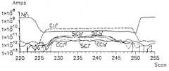
다음으로, 식각레시피2는 스트리지 폴리실리콘 식각가스로서 SF6+ Cl2가스를 사용한 경우로서, 도8은 식각레시피2에 따른 스토리지 폴리실리콘 식각공정에 대한 주요 가스의 인텐시티(amplitude, ppm) 트렌드를 RGA-QMS로 분석한 결과를 나타내며, 도9는 도8의 주식각단계의 172 스캔에서의 스펙트럼을 나타내며, 도10은 식각레시피2에 따른 스토리지 폴리실리콘 식각공정에 대한 식각과정을 OES로 분석한 결과를 나타낸다.Next, the
상기 식각레시피2에서는 폴리실리콘을 SF6+ Cl2가스를 이용하여 주식각한 후 Cl2가스를 이용하여 과식각한다. SF6자체는 불활성가스이나 RF장에서는 리액티브 플루오라이드 이온을 형성하여 Cl2가스와 함께 폴리실리콘 식각에 사용될 수 있다.In the
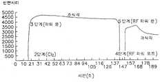
도5 및 도6의 분석결과로부터 SF6와 Cl2가스가 에천트로 작용하여 생성되는 주요 생성물은 SiFx(SiF+, SiF2+, SiF3+)가스이며, SiClxFy(SiCl+, SiClF2+, SiCl2F2+, SiCl2F+, SiClF3+)가스의 형태로도 식각됨을 알 수 있으며, RGA-QMS상의 가스의 거동은 도10의 EPD(End Point Detection) 스펙트럼의 결과와 잘 일치함을 알 수 있다. 도10에서 RF 파워온되는 3단계 이후 주식각이 이루어지며, RF 파워오프되는 4단계를 거쳐 안정화된 후 RF 파워온되는 5단계 후 과식각공정이 수행되는 것을 알 수 있다.From the analysis results of FIGS. 5 and 6, the main products generated by the action of SF6 and Cl2 as an etchant are SiFx (SiF+ , SiF2+ , SiF3+ ) gas, and SiClx Fy (SiCl+ , SiClF2+ , SiCl2 F2+ , SiCl2 F+ , SiClF3+ ) can be etched in the form of gas, the behavior of the gas on the RGA-QMS results of the EPD (End Point Detection) spectrum of FIG. It can be seen that it agrees well with. In FIG. 10, the stock angle is formed after three steps of RF power-on, and after the five steps of RF power-on, after the stabilization is performed through four steps of RF power-off, the over-etching process is performed.
본 발명의 실시예에서 식각챔버를 인시튜로 세정하는 공정은 3 단계로 이루어진다. 즉, 에천트로서 SF6+ Cl2가스를 사용하는 식각단계, Cl2가스를 사용하는 에이징(aging)단계 및 폐가스에 대한 펌핑단계로 이루어진다.In an embodiment of the present invention, the process of cleaning the etching chamber in situ comprises three steps. That is, an etching step using SF6 + Cl2 gas as an etchant, an aging step using Cl2 gas, and a pumping step for waste gas.
도11은 본 발명의 일 실시예에 따른 식각챔버 인시튜 세정시 식각시간을 60초로 하여 주요가스의 트렌드를 RGA-QMS로 분석한 결과를 나타내며, F 원자가 리액티브 에천트로 작용하여 식각챔버 내의 폴리머를 SiFX의 형태로 식각함을 알 수 있다. 그 밖에 SOF+, SO2+, 등의 부산물도 검출됨을 알 수 있다.11 shows the results of analyzing the trend of the main gas by RGA-QMS with an etching time of 60 seconds during the etching chamber in-situ cleaning according to an embodiment of the present invention, the F atoms act as a reactive etchant for the polymer in the etching chamber It can be seen that the etching in the form of SiFX. In addition, it can be seen that by-products such as SOF+ , SO2+ , and the like are also detected.
도11로부터 식각(세정)의 주 생성물인 SiF3+는 식각 시작 직후 급격히 증가하였다가 서서히 감소하고 식각이 끝나자 사라져 엔드 포인트를 정확하게 확인할 수 없었다. 도12는 도11에 비하여 식각시간을 120초로 연장한 식각챔버 인시튜 세정시 주요가스의 트렌드를 RGA-QMS로 분석한 결과를 나타낸다. 도12로부터 약 74초에서 식각이 완료됨을 알 수 있다.FIG main product, SiF3+ of the etched (cleaned) from 11 could gradually decrease was rapidly increased immediately after the etching starts and check At the end of the etching away the exact endpoint. FIG. 12 shows the result of analyzing the trend of the main gas by RGA-QMS during the cleaning of the etching chamber in-situ with the etching time extended to 120 seconds compared to FIG. It can be seen from FIG. 12 that the etching is completed in about 74 seconds.
도13은 상기 식각시간을 변경평가하여 최적화된 식각챔버 인시튜 세정시FIG. 13 shows an optimized etching chamber in-situ cleaning by changing and evaluating the etching time. FIG.
주요가스의 트렌드를 RGA-QMS로 분석한 결과를 나타낸다. 즉, SF6+ Cl2가스를 이용하여 식각하는 식각단계는 시간 100초, 압력 15 mt 및 RF파워 400W 하에서 수행하며, 에이징단계는 시간 30초, 압력 20 mt, RF 파워 400W 하에서 Cl2가스하에서 수행하며, 질소가스를 일부 공급해준다. RF 파워를 오프시킨 후 펌핑단계를 300초간 수행하였다.The trend of major gas is analyzed by RGA-QMS. In other words, the etching step using SF6 + Cl2 gas is performed under
상기 본 발명의 인시튜 세정공정의 효과를 파악하기 위하여 파티클분석과 에이징시 실리콘 옥사이드 웨이퍼 표면의 파티클을 서프스캔(SUFSCAN)으로 분석한 바에 의하면, 인시튜 세정공정 후에도 파티클수가 줄어드는 것을 알 수 있었다.In order to understand the effect of the in-situ cleaning process of the present invention, the particle number on the surface of the silicon oxide wafer was analyzed by SUFSCAN during particle analysis and aging.
한편, 세정공정의 전후에서 식각챔버내의 Fe, Cr, Ni, Zn, Ti, S, Cl, F, NH4등의 금속성/이온성 불순물을 TXRF (Total X-ray Reflection Fluorescence) /HPIC(High Performance Ion Chromatography)로 측정하여 세정공정의 효과를 판단할 수도 있다.Meanwhile, before and after the cleaning process, metallic / ionic impurities such as Fe, Cr, Ni, Zn, Ti, S, Cl, F, and NH4 in the etching chamber may be removed by TXRF (Total X-ray Reflection Fluorescence) / HPIC (High Performance). Ion Chromatography may be used to determine the effectiveness of the cleaning process.
따라서, 본 발명에 의하면 RGA-QMS를 이용하여 식각챔버를 인시튜 모니터링함으로써 식각공정과 세정공정 중의 실제 가스상의 반응메카니즘을 평가할 수 있었으며, 이를 토대로 폴리실리콘 식각시 리액티브 에천트, 반응생성물을 확인 규명하여 반응메카니즘과 엔드포인트를 정확하게 확인할 수 있었으며, 세정공정시 식각시간을 최적화하여 불필요한 세정시간을 감소시켰으며, 파티클 발생을 억제하였으며, 설비의 가동율도 향상시키는 효과가 있다.Therefore, according to the present invention, the in-situ monitoring of the etching chamber using RGA-QMS was able to evaluate the reaction mechanism of the actual gas phase during the etching process and the cleaning process. Based on this, the reactive etchant and the reaction product were identified during polysilicon etching. By identifying the reaction mechanism and the endpoint, it was possible to identify the reaction mechanism and the endpoint accurately. By optimizing the etching time during the cleaning process, unnecessary washing time was reduced, particle generation was suppressed, and the operation rate of the equipment was also improved.
이상에서 본 발명은 기재된 구체예에 대해서만 상세히 설명되었지만 본 발명의 기술사상 범위 내에서 다양한 변형 및 수정이 가능함은 당업자에게 있어서 명백한 것이며, 이러한 변형 및 수정이 첨부된 특허청구범위에 속함은 당연한 것이다.Although the present invention has been described in detail only with respect to the described embodiments, it will be apparent to those skilled in the art that various modifications and variations are possible within the technical scope of the present invention, and such modifications and modifications are within the scope of the appended claims.
Claims (32)
Translated fromKoreanPriority Applications (8)
| Application Number | Priority Date | Filing Date | Title |
|---|---|---|---|
| KR1019970079194AKR100257903B1 (en) | 1997-12-30 | 1997-12-30 | Plasma etching apparatus capable of in-situ monitoring, its in-situ monitoring method and in-situ cleaning method for removing residues in plasma etching chamber |
| TW087114950ATW473771B (en) | 1997-12-30 | 1998-09-08 | In-situ monitoring plasma etching apparatus, its in-situ monitoring method, and in-situ cleaning method for removing residues in a plasma etching chamber |
| JP25484198AJP3636422B2 (en) | 1997-12-30 | 1998-09-09 | Plasma etching apparatus, in-situ monitoring method and in-situ cleaning method |
| CNB981200508ACN1227389C (en) | 1997-12-30 | 1998-09-28 | On-site monitoring plasma etching device and method |
| GB9821040AGB2332881B (en) | 1997-12-30 | 1998-09-28 | Plasma process apparatus having in situ monitoring and a monitoring method for use in such apparatus |
| DE19844882ADE19844882B4 (en) | 1997-12-30 | 1998-09-30 | Apparatus for plasma processing with in-situ monitoring and in situ monitoring method for such a device |
| US09/172,140US6146492A (en) | 1997-12-30 | 1998-10-14 | Plasma process apparatus with in situ monitoring, monitoring method, and in situ residue cleaning method |
| US09/633,893US6499492B1 (en) | 1997-12-30 | 2000-08-07 | Plasma process apparatus with in situ monitoring, monitoring method, and in situ residue cleaning |
Applications Claiming Priority (1)
| Application Number | Priority Date | Filing Date | Title |
|---|---|---|---|
| KR1019970079194AKR100257903B1 (en) | 1997-12-30 | 1997-12-30 | Plasma etching apparatus capable of in-situ monitoring, its in-situ monitoring method and in-situ cleaning method for removing residues in plasma etching chamber |
Publications (2)
| Publication Number | Publication Date |
|---|---|
| KR19990058999A KR19990058999A (en) | 1999-07-26 |
| KR100257903B1true KR100257903B1 (en) | 2000-08-01 |
Family
ID=19530073
Family Applications (1)
| Application Number | Title | Priority Date | Filing Date |
|---|---|---|---|
| KR1019970079194AExpired - Fee RelatedKR100257903B1 (en) | 1997-12-30 | 1997-12-30 | Plasma etching apparatus capable of in-situ monitoring, its in-situ monitoring method and in-situ cleaning method for removing residues in plasma etching chamber |
Country Status (7)
| Country | Link |
|---|---|
| US (2) | US6146492A (en) |
| JP (1) | JP3636422B2 (en) |
| KR (1) | KR100257903B1 (en) |
| CN (1) | CN1227389C (en) |
| DE (1) | DE19844882B4 (en) |
| GB (1) | GB2332881B (en) |
| TW (1) | TW473771B (en) |
Cited By (5)
| Publication number | Priority date | Publication date | Assignee | Title |
|---|---|---|---|---|
| KR100478034B1 (en)* | 2000-11-06 | 2005-03-21 | 알프스 덴키 가부시키가이샤 | Performance evaluating method for plasma processing apparatus |
| US7446367B2 (en) | 2005-05-30 | 2008-11-04 | Samsung Electronics Co., Ltd. | Reliable gap-filling process and apparatus for performing the process in the manufacturing of semiconductor devices |
| KR101046918B1 (en)* | 2003-06-18 | 2011-07-07 | 어플라이드 머티어리얼스, 인코포레이티드 | Method and system for monitoring the etching process |
| KR102140711B1 (en) | 2019-10-17 | 2020-08-03 | 주식회사 프라임솔루션 | A hi-vacuum plasma residual gas analizer and method for analysing residua gas of the same |
| WO2022047299A1 (en)* | 2020-08-31 | 2022-03-03 | Applied Materials, Inc. | Method and hardware for post maintenance vacuum recovery system |
Families Citing this family (40)
| Publication number | Priority date | Publication date | Assignee | Title |
|---|---|---|---|---|
| JP2644912B2 (en)* | 1990-08-29 | 1997-08-25 | 株式会社日立製作所 | Vacuum processing apparatus and operating method thereof |
| US6468814B1 (en)* | 1998-07-24 | 2002-10-22 | Leybold Inficon, Inc. | Detection of nontransient processing anomalies in vacuum manufacturing process |
| IES20010113A2 (en)* | 2000-02-11 | 2001-09-19 | Anthony Herbert | An atmospheric pressure plasma system |
| US6887337B2 (en) | 2000-09-19 | 2005-05-03 | Xactix, Inc. | Apparatus for etching semiconductor samples and a source for providing a gas by sublimation thereto |
| US6627463B1 (en)* | 2000-10-19 | 2003-09-30 | Applied Materials, Inc. | Situ measurement of film nitridation using optical emission spectroscopy |
| US6964187B2 (en)* | 2001-03-20 | 2005-11-15 | Mykrolis Corporation | Vacuum sensor |
| JP4627916B2 (en)* | 2001-03-29 | 2011-02-09 | キヤノンアネルバ株式会社 | Ionizer |
| US6776851B1 (en)* | 2001-07-11 | 2004-08-17 | Lam Research Corporation | In-situ cleaning of a polymer coated plasma processing chamber |
| US20030027428A1 (en)* | 2001-07-18 | 2003-02-06 | Applied Materials, Inc. | Bypass set up for integration of remote optical endpoint for CVD chamber |
| US7227624B2 (en)* | 2001-07-24 | 2007-06-05 | Tokyo Electron Limited | Method and apparatus for monitoring the condition of plasma equipment |
| JP3660896B2 (en)* | 2001-07-26 | 2005-06-15 | 株式会社日立製作所 | Maintenance method of plasma processing apparatus |
| JP2003086574A (en)* | 2001-09-07 | 2003-03-20 | Mitsubishi Electric Corp | Gas analysis method for semiconductor processing apparatus and apparatus therefor |
| GB0206158D0 (en)* | 2002-03-15 | 2002-04-24 | Intellemetrics Ltd | Use of light emitting chemical reactions for control of semiconductor production processes |
| US7153362B2 (en)* | 2002-04-30 | 2006-12-26 | Samsung Electronics Co., Ltd. | System and method for real time deposition process control based on resulting product detection |
| US20030221708A1 (en)* | 2002-06-04 | 2003-12-04 | Chun-Hao Ly | Method of cleaning a semiconductor process chamber |
| US6919279B1 (en) | 2002-10-08 | 2005-07-19 | Novellus Systems, Inc. | Endpoint detection for high density plasma (HDP) processes |
| US7010374B2 (en)* | 2003-03-04 | 2006-03-07 | Hitachi High-Technologies Corporation | Method for controlling semiconductor processing apparatus |
| CN1295757C (en)* | 2003-03-04 | 2007-01-17 | 株式会社日立高新技术 | Control method of semiconductor processing device |
| US20040237888A1 (en)* | 2003-05-30 | 2004-12-02 | General Electric Company | Optical monitoring system for plasma enhanced chemical vapor deposition |
| US20050220984A1 (en)* | 2004-04-02 | 2005-10-06 | Applied Materials Inc., A Delaware Corporation | Method and system for control of processing conditions in plasma processing systems |
| US20060075968A1 (en)* | 2004-10-12 | 2006-04-13 | Applied Materials, Inc. | Leak detector and process gas monitor |
| DE102004061269A1 (en)* | 2004-12-10 | 2006-06-14 | Siemens Ag | Method for cleaning a workpiece with halogen ions |
| JP4343875B2 (en)* | 2005-06-08 | 2009-10-14 | Tdk株式会社 | Etching amount measuring apparatus, etching apparatus and etching amount measuring method |
| CN100423186C (en)* | 2005-10-31 | 2008-10-01 | 中芯国际集成电路制造(上海)有限公司 | Method and device for vacuum system to prevent wafer particle defects |
| US20090014644A1 (en)* | 2007-07-13 | 2009-01-15 | Inficon, Inc. | In-situ ion source cleaning for partial pressure analyzers used in process monitoring |
| US8158017B2 (en)* | 2008-05-12 | 2012-04-17 | Lam Research Corporation | Detection of arcing events in wafer plasma processing through monitoring of trace gas concentrations |
| US8003959B2 (en)* | 2009-06-26 | 2011-08-23 | Varian Semiconductor Equipment Associates, Inc. | Ion source cleaning end point detection |
| US8580585B2 (en)* | 2009-12-18 | 2013-11-12 | Micrel, Inc. | Method and system for controlled isotropic etching on a plurality of etch systems |
| DE102011014866A1 (en)* | 2011-03-24 | 2012-09-27 | Carl Zeiss Jena Gmbh | Arrangement for monitoring and controlling of plasma etching process of workpiece, has image processing and simulation device that controls operation of ion beam source based on the measurement data of locator and detector array |
| CN102820197B (en)* | 2012-08-31 | 2016-03-09 | 中微半导体设备(上海)有限公司 | A kind of plasma handling system |
| CN104157568B (en)* | 2013-05-14 | 2017-02-22 | 北大方正集团有限公司 | Method and device for removing silicon slag |
| CN105161395A (en)* | 2015-08-11 | 2015-12-16 | 上海华力微电子有限公司 | Plasma etching apparatus and plasma etching method |
| US10871477B2 (en)* | 2015-08-20 | 2020-12-22 | The United States Of America, As Represented By The Secretary Of The Navy | Contaminant cleaning systems and related methods using one or more reactive substances, reaction byproduct measurements, and differential pressure or vacuum transfer of the reactive substances and reaction byproducts |
| JP6767257B2 (en)* | 2016-12-22 | 2020-10-14 | 東京エレクトロン株式会社 | Substrate processing equipment and substrate processing method |
| CN111197157A (en)* | 2018-11-16 | 2020-05-26 | 长鑫存储技术有限公司 | Semiconductor manufacturing device with real-time monitoring function of process chamber |
| CN110220842B (en)* | 2019-05-13 | 2021-07-27 | 江苏天楹环保能源成套设备有限公司 | Electrode ablation detection tool and detection method thereof |
| US20230045932A1 (en)* | 2020-01-17 | 2023-02-16 | ATIK Co., Ltd. | System for stabilizing flow of gas introduced into sensor |
| CN112067565B (en)* | 2020-09-22 | 2023-01-17 | 江苏师范大学 | A metal corrosion state evaluation test device and method based on wavelength change |
| US11635338B2 (en)* | 2020-10-23 | 2023-04-25 | Applied Materials, Inc. | Rapid chamber vacuum leak check hardware and maintenance routine |
| KR20230105522A (en) | 2022-01-04 | 2023-07-11 | 에이피시스템 주식회사 | Apparatus for processing substrate and method for cleaning the same |
Family Cites Families (26)
| Publication number | Priority date | Publication date | Assignee | Title |
|---|---|---|---|---|
| US4214946A (en)* | 1979-02-21 | 1980-07-29 | International Business Machines Corporation | Selective reactive ion etching of polysilicon against SiO2 utilizing SF6 -Cl2 -inert gas etchant |
| JPS62151562A (en)* | 1985-12-26 | 1987-07-06 | Mitsubishi Electric Corp | Thin film forming equipment |
| JPS62210483A (en)* | 1986-03-12 | 1987-09-16 | Ricoh Co Ltd | Multicolor developing device for copying device |
| US4786352A (en)* | 1986-09-12 | 1988-11-22 | Benzing Technologies, Inc. | Apparatus for in-situ chamber cleaning |
| JPH03261062A (en)* | 1990-03-09 | 1991-11-20 | Hitachi Ltd | Plasma trace element mass spectrometer |
| JP2753103B2 (en)* | 1990-03-23 | 1998-05-18 | 松下電子工業株式会社 | Plasma etching method for aluminum alloy film |
| US5290383A (en)* | 1991-03-24 | 1994-03-01 | Tokyo Electron Limited | Plasma-process system with improved end-point detecting scheme |
| JPH04313223A (en)* | 1991-04-04 | 1992-11-05 | Mitsubishi Electric Corp | Manufacturing method of semiconductor device |
| JPH0521394A (en)* | 1991-07-16 | 1993-01-29 | Nec Corp | Plasma processor |
| JPH05234959A (en)* | 1991-08-16 | 1993-09-10 | Hitachi Ltd | Dry etching method and dry etching apparatus |
| JPH0775230B2 (en)* | 1991-09-24 | 1995-08-09 | 株式会社小電力高速通信研究所 | Plasma etching end point monitoring method |
| JPH05152254A (en)* | 1991-11-29 | 1993-06-18 | Nec Corp | Dryetching system |
| JPH05291188A (en)* | 1992-04-08 | 1993-11-05 | Hitachi Ltd | Parameter monitoring system for plasma processing equipment |
| US5421957A (en)* | 1993-07-30 | 1995-06-06 | Applied Materials, Inc. | Low temperature etching in cold-wall CVD systems |
| JPH07106305A (en)* | 1993-10-06 | 1995-04-21 | Hitachi Ltd | Atomic layer etching equipment |
| US5427621A (en)* | 1993-10-29 | 1995-06-27 | Applied Materials, Inc. | Method for removing particulate contaminants by magnetic field spiking |
| JPH0837175A (en)* | 1994-07-21 | 1996-02-06 | Kokusai Electric Co Ltd | Pollution measurement method |
| US5504328A (en)* | 1994-12-09 | 1996-04-02 | Sematech, Inc. | Endpoint detection utilizing ultraviolet mass spectrometry |
| JP3386287B2 (en)* | 1995-05-08 | 2003-03-17 | 堀池 靖浩 | Plasma etching equipment |
| JPH09129709A (en)* | 1995-10-27 | 1997-05-16 | Nec Corp | Processing apparatus |
| US5652170A (en)* | 1996-01-22 | 1997-07-29 | Micron Technology, Inc. | Method for etching sloped contact openings in polysilicon |
| US5900105A (en)* | 1996-07-09 | 1999-05-04 | Gamma Precision Technology, Inc. | Wafer transfer system and method of using the same |
| US5928426A (en)* | 1996-08-08 | 1999-07-27 | Novellus Systems, Inc. | Method and apparatus for treating exhaust gases from CVD, PECVD or plasma etch reactors |
| US6095158A (en)* | 1997-02-06 | 2000-08-01 | Lam Research Corporation | Anhydrous HF in-situ cleaning process of semiconductor processing chambers |
| US5966586A (en)* | 1997-09-26 | 1999-10-12 | Lam Research Corporation | Endpoint detection methods in plasma etch processes and apparatus therefor |
| US6136211A (en)* | 1997-11-12 | 2000-10-24 | Applied Materials, Inc. | Self-cleaning etch process |
- 1997
- 1997-12-30KRKR1019970079194Apatent/KR100257903B1/ennot_activeExpired - Fee Related
- 1998
- 1998-09-08TWTW087114950Apatent/TW473771B/ennot_activeIP Right Cessation
- 1998-09-09JPJP25484198Apatent/JP3636422B2/ennot_activeExpired - Fee Related
- 1998-09-28CNCNB981200508Apatent/CN1227389C/ennot_activeExpired - Lifetime
- 1998-09-28GBGB9821040Apatent/GB2332881B/ennot_activeExpired - Fee Related
- 1998-09-30DEDE19844882Apatent/DE19844882B4/ennot_activeExpired - Fee Related
- 1998-10-14USUS09/172,140patent/US6146492A/ennot_activeExpired - Lifetime
- 2000
- 2000-08-07USUS09/633,893patent/US6499492B1/ennot_activeExpired - Fee Related
Cited By (7)
| Publication number | Priority date | Publication date | Assignee | Title |
|---|---|---|---|---|
| KR100478034B1 (en)* | 2000-11-06 | 2005-03-21 | 알프스 덴키 가부시키가이샤 | Performance evaluating method for plasma processing apparatus |
| US8257546B2 (en) | 2003-04-11 | 2012-09-04 | Applied Materials, Inc. | Method and system for monitoring an etch process |
| KR101046918B1 (en)* | 2003-06-18 | 2011-07-07 | 어플라이드 머티어리얼스, 인코포레이티드 | Method and system for monitoring the etching process |
| US7446367B2 (en) | 2005-05-30 | 2008-11-04 | Samsung Electronics Co., Ltd. | Reliable gap-filling process and apparatus for performing the process in the manufacturing of semiconductor devices |
| US7964473B2 (en) | 2005-05-30 | 2011-06-21 | Samsung Electronics Co., Ltd. | Method of filling an opening in the manufacturing of a semiconductor device |
| KR102140711B1 (en) | 2019-10-17 | 2020-08-03 | 주식회사 프라임솔루션 | A hi-vacuum plasma residual gas analizer and method for analysing residua gas of the same |
| WO2022047299A1 (en)* | 2020-08-31 | 2022-03-03 | Applied Materials, Inc. | Method and hardware for post maintenance vacuum recovery system |
Also Published As
| Publication number | Publication date |
|---|---|
| GB2332881A (en) | 1999-07-07 |
| US6146492A (en) | 2000-11-14 |
| CN1221807A (en) | 1999-07-07 |
| CN1227389C (en) | 2005-11-16 |
| TW473771B (en) | 2002-01-21 |
| US6499492B1 (en) | 2002-12-31 |
| DE19844882B4 (en) | 2007-02-01 |
| GB2332881B (en) | 2002-04-10 |
| KR19990058999A (en) | 1999-07-26 |
| DE19844882A1 (en) | 1999-07-08 |
| JP3636422B2 (en) | 2005-04-06 |
| JPH11204509A (en) | 1999-07-30 |
| GB9821040D0 (en) | 1998-11-18 |
Similar Documents
| Publication | Publication Date | Title |
|---|---|---|
| KR100257903B1 (en) | Plasma etching apparatus capable of in-situ monitoring, its in-situ monitoring method and in-situ cleaning method for removing residues in plasma etching chamber | |
| KR100253089B1 (en) | Chemical vapor deposition apparatus | |
| US7028696B2 (en) | Plasma cleaning of deposition chamber residues using duo-step wafer-less auto clean method | |
| US7959970B2 (en) | System and method of removing chamber residues from a plasma processing system in a dry cleaning process | |
| US8257503B2 (en) | Method and apparatus for detecting plasma unconfinement | |
| US20130193108A1 (en) | Methods of end point detection for substrate fabrication processes | |
| US20040263827A1 (en) | Novel methodology for in-situ and real-time chamber condition monitoring and process recovery during plasma processing | |
| KR100557673B1 (en) | How to Season Plasma Equipment | |
| JP7646289B2 (en) | In-situ, real-time plasma chamber condition monitoring | |
| US6335284B1 (en) | Metallization process for manufacturing semiconductor devices | |
| WO2002000962A1 (en) | System and method for in-situ cleaning of process monitor of semi-conductor wafer fabricator | |
| JPH0896988A (en) | Plasma monitoring device and plasma monitoring method | |
| JP2001257197A (en) | Semiconductor device manufacturing method and manufacturing apparatus | |
| JP2005019763A (en) | Dry etching device | |
| Hussla et al. | 5HE, UK | |
| KR20070047415A (en) | End point detection method of substrate processing process and apparatus for performing the same |
Legal Events
| Date | Code | Title | Description |
|---|---|---|---|
| A201 | Request for examination | ||
| PA0109 | Patent application | St.27 status event code:A-0-1-A10-A12-nap-PA0109 | |
| PA0201 | Request for examination | St.27 status event code:A-1-2-D10-D11-exm-PA0201 | |
| R17-X000 | Change to representative recorded | St.27 status event code:A-3-3-R10-R17-oth-X000 | |
| R18-X000 | Changes to party contact information recorded | St.27 status event code:A-3-3-R10-R18-oth-X000 | |
| PN2301 | Change of applicant | St.27 status event code:A-3-3-R10-R13-asn-PN2301 St.27 status event code:A-3-3-R10-R11-asn-PN2301 | |
| PG1501 | Laying open of application | St.27 status event code:A-1-1-Q10-Q12-nap-PG1501 | |
| PN2301 | Change of applicant | St.27 status event code:A-3-3-R10-R13-asn-PN2301 St.27 status event code:A-3-3-R10-R11-asn-PN2301 | |
| E701 | Decision to grant or registration of patent right | ||
| PE0701 | Decision of registration | St.27 status event code:A-1-2-D10-D22-exm-PE0701 | |
| GRNT | Written decision to grant | ||
| PR0701 | Registration of establishment | St.27 status event code:A-2-4-F10-F11-exm-PR0701 | |
| PR1002 | Payment of registration fee | St.27 status event code:A-2-2-U10-U11-oth-PR1002 Fee payment year number:1 | |
| PG1601 | Publication of registration | St.27 status event code:A-4-4-Q10-Q13-nap-PG1601 | |
| R18-X000 | Changes to party contact information recorded | St.27 status event code:A-5-5-R10-R18-oth-X000 | |
| PN2301 | Change of applicant | St.27 status event code:A-5-5-R10-R13-asn-PN2301 St.27 status event code:A-5-5-R10-R11-asn-PN2301 | |
| R18-X000 | Changes to party contact information recorded | St.27 status event code:A-5-5-R10-R18-oth-X000 | |
| R18-X000 | Changes to party contact information recorded | St.27 status event code:A-5-5-R10-R18-oth-X000 | |
| PR1001 | Payment of annual fee | St.27 status event code:A-4-4-U10-U11-oth-PR1001 Fee payment year number:4 | |
| R18-X000 | Changes to party contact information recorded | St.27 status event code:A-5-5-R10-R18-oth-X000 | |
| PR1001 | Payment of annual fee | St.27 status event code:A-4-4-U10-U11-oth-PR1001 Fee payment year number:5 | |
| PR1001 | Payment of annual fee | St.27 status event code:A-4-4-U10-U11-oth-PR1001 Fee payment year number:6 | |
| PN2301 | Change of applicant | St.27 status event code:A-5-5-R10-R13-asn-PN2301 St.27 status event code:A-5-5-R10-R11-asn-PN2301 | |
| PN2301 | Change of applicant | St.27 status event code:A-5-5-R10-R13-asn-PN2301 St.27 status event code:A-5-5-R10-R11-asn-PN2301 | |
| PR1001 | Payment of annual fee | St.27 status event code:A-4-4-U10-U11-oth-PR1001 Fee payment year number:7 | |
| PR1001 | Payment of annual fee | St.27 status event code:A-4-4-U10-U11-oth-PR1001 Fee payment year number:8 | |
| FPAY | Annual fee payment | Payment date:20080303 Year of fee payment:9 | |
| PR1001 | Payment of annual fee | St.27 status event code:A-4-4-U10-U11-oth-PR1001 Fee payment year number:9 | |
| LAPS | Lapse due to unpaid annual fee | ||
| PC1903 | Unpaid annual fee | St.27 status event code:A-4-4-U10-U13-oth-PC1903 Not in force date:20090307 Payment event data comment text:Termination Category : DEFAULT_OF_REGISTRATION_FEE | |
| PC1903 | Unpaid annual fee | St.27 status event code:N-4-6-H10-H13-oth-PC1903 Ip right cessation event data comment text:Termination Category : DEFAULT_OF_REGISTRATION_FEE Not in force date:20090307 | |
| R18-X000 | Changes to party contact information recorded | St.27 status event code:A-5-5-R10-R18-oth-X000 |