KR100256927B1 - Shield connection system of high speed cable - Google Patents
Shield connection system of high speed cableDownload PDFInfo
- Publication number
- KR100256927B1 KR100256927B1KR1019970006843AKR19970006843AKR100256927B1KR 100256927 B1KR100256927 B1KR 100256927B1KR 1019970006843 AKR1019970006843 AKR 1019970006843AKR 19970006843 AKR19970006843 AKR 19970006843AKR 100256927 B1KR100256927 B1KR 100256927B1
- Authority
- KR
- South Korea
- Prior art keywords
- additional
- pair
- metal shield
- ground plate
- sleeve
- Prior art date
- Legal status (The legal status is an assumption and is not a legal conclusion. Google has not performed a legal analysis and makes no representation as to the accuracy of the status listed.)
- Expired - Fee Related
Links
Images


Classifications
- H—ELECTRICITY
- H01—ELECTRIC ELEMENTS
- H01R—ELECTRICALLY-CONDUCTIVE CONNECTIONS; STRUCTURAL ASSOCIATIONS OF A PLURALITY OF MUTUALLY-INSULATED ELECTRICAL CONNECTING ELEMENTS; COUPLING DEVICES; CURRENT COLLECTORS
- H01R13/00—Details of coupling devices of the kinds covered by groups H01R12/70 or H01R24/00 - H01R33/00
- H01R13/648—Protective earth or shield arrangements on coupling devices, e.g. anti-static shielding
- H01R13/658—High frequency shielding arrangements, e.g. against EMI [Electro-Magnetic Interference] or EMP [Electro-Magnetic Pulse]
- H01R13/6591—Specific features or arrangements of connection of shield to conductive members
- H01R13/65912—Specific features or arrangements of connection of shield to conductive members for shielded multiconductor cable
- H01R13/65918—Specific features or arrangements of connection of shield to conductive members for shielded multiconductor cable wherein each conductor is individually surrounded by shield
- H—ELECTRICITY
- H01—ELECTRIC ELEMENTS
- H01R—ELECTRICALLY-CONDUCTIVE CONNECTIONS; STRUCTURAL ASSOCIATIONS OF A PLURALITY OF MUTUALLY-INSULATED ELECTRICAL CONNECTING ELEMENTS; COUPLING DEVICES; CURRENT COLLECTORS
- H01R13/00—Details of coupling devices of the kinds covered by groups H01R12/70 or H01R24/00 - H01R33/00
- H01R13/648—Protective earth or shield arrangements on coupling devices, e.g. anti-static shielding
- H—ELECTRICITY
- H01—ELECTRIC ELEMENTS
- H01R—ELECTRICALLY-CONDUCTIVE CONNECTIONS; STRUCTURAL ASSOCIATIONS OF A PLURALITY OF MUTUALLY-INSULATED ELECTRICAL CONNECTING ELEMENTS; COUPLING DEVICES; CURRENT COLLECTORS
- H01R9/00—Structural associations of a plurality of mutually-insulated electrical connecting elements, e.g. terminal strips or terminal blocks; Terminals or binding posts mounted upon a base or in a case; Bases therefor
- H01R9/03—Connectors arranged to contact a plurality of the conductors of a multiconductor cable, e.g. tapping connections
- H01R9/05—Connectors arranged to contact a plurality of the conductors of a multiconductor cable, e.g. tapping connections for coaxial cables
- H01R9/0512—Connections to an additional grounding conductor
- H—ELECTRICITY
- H01—ELECTRIC ELEMENTS
- H01R—ELECTRICALLY-CONDUCTIVE CONNECTIONS; STRUCTURAL ASSOCIATIONS OF A PLURALITY OF MUTUALLY-INSULATED ELECTRICAL CONNECTING ELEMENTS; COUPLING DEVICES; CURRENT COLLECTORS
- H01R9/00—Structural associations of a plurality of mutually-insulated electrical connecting elements, e.g. terminal strips or terminal blocks; Terminals or binding posts mounted upon a base or in a case; Bases therefor
- H01R9/03—Connectors arranged to contact a plurality of the conductors of a multiconductor cable, e.g. tapping connections
- H01R9/05—Connectors arranged to contact a plurality of the conductors of a multiconductor cable, e.g. tapping connections for coaxial cables
- H01R9/0518—Connection to outer conductor by crimping or by crimping ferrule
Landscapes
- Details Of Connecting Devices For Male And Female Coupling (AREA)
- Cable Accessories (AREA)
- Shielding Devices Or Components To Electric Or Magnetic Fields (AREA)
- Manufacturing Of Electrical Connectors (AREA)
- Connections Effected By Soldering, Adhesion, Or Permanent Deformation (AREA)
- Coupling Device And Connection With Printed Circuit (AREA)
- Insulated Conductors (AREA)
Abstract
Translated fromKoreanDescription
Translated fromKorean본 발명은 전기 커넥터 분야에 관한 것으로, 특히 케이블의 금속 브레이드 (braid)와 같은 고속 케이블의 금속성 차폐부를 접속하는 시스템에 관한 것이다.TECHNICAL FIELD The present invention relates to the field of electrical connectors, and more particularly to a system for connecting metallic shields of high speed cables, such as metal braids of cables.
통상의 고속 케이블은 튜브형 내부 유전체로 둘러싸인 중심 도체 또는 코어를 포함한다. 차폐부는 케이블을 차폐 및/또는 접지하기 위하여 내부 유전체 외부에 배치되어 있다. 대개, 차폐부는 튜브형 금속 브레이드로 되어 있다. 그러나, 하나 이상의 종방향 도전성 와이어도 사용되며, 이는 대개 "드레인 와이어(drain wire)"라고 불려진다. 절연 재킷은 차폐부의 외부에서 복합 케이블을 둘러싼다.Typical high speed cables include a central conductor or core surrounded by a tubular inner dielectric. The shield is disposed outside the internal dielectric to shield and / or ground the cable. Usually the shield is of a tubular metal braid. However, one or more longitudinal conductive wires are also used, which are usually referred to as "drain wires". An insulating jacket surrounds the composite cable on the outside of the shield.
고속 케이블을 접속하는 데에는 여러 형태의 커넥터가 사용된다. 대개, 이들 커넥터는 케이블의 중심 도체 또는 코어에 접속되는 접점들을 갖는다. 또한, 커넥터는 통상적으로는 접지 목적으로 고속 케이블의 금속 차폐부를 접속하기 위해 한가지 형태 또는 다른 형태의 접속 부재도 갖는다. 이러한 커넥터에서의 대표적인 시스템은 금속 차폐부를 납땜에 의해 저속 부재에 접속한다. 또 다른 시스템으로는 동일 목적을 위하여 접속 부재의 적어도 일부를 금속 브레이드에 견고하게 크림핑하는 크림핑 공정을 사용하는 것도 있다.Several types of connectors are used to connect high speed cables. Usually, these connectors have contacts that connect to the core conductor or core of the cable. Also, connectors typically have one or another type of connection member for connecting the metal shield of a high speed cable for grounding purposes. A representative system in such a connector connects the metal shield to the low speed member by soldering. Another system is to use a crimping process for firmly crimping at least part of the connection member onto the metal braid for the same purpose.
컴퓨터 및 전기 통신 산업 등의 여러 산업 분야에서 전자장치 및 이와 관련한 전기 커넥터를 소형화하려는 노력이 끊임없이 계속되면서 소형 고속 케이블, 특히 케이블의 금속 차폐부를 접속함에 있어 심각한 문제점을 직면하게 되었다. 예를 들어, 소형 동축 케이블의 외경은 0.2286cm (0.090inch)정도이다. 도체/코어를 둘러싸는 내부 유전체의 외경은 0.1295cm (0.051inch) 정도이며, 중심 도체/코어의 직경은 0.0304cm (0.012inch) 정도이다. 동축 케이블로서는 매우 작은 치수 파라미터를 갖는 것이 사용되었다.In many industries, such as the computer and telecommunications industries, efforts to miniaturize electronic devices and related electrical connectors continue to face serious problems in connecting small high speed cables, particularly metal shields of cables. For example, the outer diameter of a small coaxial cable is about 0.2286 cm (0.090 inch). The outer diameter of the inner dielectric surrounding the conductor / core is about 0.1295 cm (0.051 inch), and the diameter of the center conductor / core is about 0.0304 cm (0.012 inch). As the coaxial cable, one having a very small dimensional parameter was used.
이러한 매우 작은 동축 케이블을 접속하는 데 따른 문제점으로는 케이블의 금속 차폐부를 접속할 때 나타난다. 예를 들어, 납땜 방법을 사용하는 경우에 금속 차폐부에 근접한 부분에 (납땜에 필요한) 열을 직접 인가하면 아래쪽에 있는 내부 유전체에 열 손상을 일으킬 수 있으며, 내부 유전체를 실질적으로 붕괴시키거나 약화시키게 된다. 종래의 크림프형 접속부를 사용하면, 크림핑력이 케이블의 중심 도체/코어를 둘러싸는 내부 유전체를 파손시키거나 변형시키게 된다.A problem with connecting such very small coaxial cables is when connecting the metal shield of the cable. For example, in the case of using the soldering method, direct application of heat (needed for soldering) directly to the metal shield can cause thermal damage to the underlying internal dielectric, which can substantially collapse or weaken the internal dielectric. Let's go. Using conventional crimped connections, the crimping force breaks or deforms the internal dielectric surrounding the center conductor / core of the cable.
상기 문제점들은 고속 케이블의 금속 차폐부가 원통형 접속 부재에 접속되지 않고 평평한 접속 부재 또는 접점에 접속되는 경우에 더 복잡해진다. 예를 들어, 동축 케이블의 튜브형 금속 차폐부 또는 브레이드를 인쇄회로기판 상의 평평한 접지회로 패드에 접속하는 방법이 공지되어 있다. 이러한 접속은 동축 케이블의 튜브형 금속 브레이드를 꼬인 스트랜드 또는 "피그테일"로 간단하게 모아서 회로기판 상의 평평한 접지 패드에 납땜함으로써 얻어진다.The above problems are further complicated when the metal shield of the high speed cable is connected to a flat connection member or a contact rather than to a cylindrical connection member. For example, a method of connecting a tubular metal shield or braid of a coaxial cable to a flat ground circuit pad on a printed circuit board is known. This connection is obtained by simply gathering a coaxial cable's tubular metal braid into twisted strands or "pigtails" and soldering them to a flat ground pad on a circuit board.
동축 케이블의 금속 차폐부 또는 브레이드를 평탄한 접지 부재에 접속하는 또 다른 예가 본 발명의 양수인에게 양도된 1994년 4월 19일자 미국 특허 제5,304,069호에 개시되어 있다. 이 특허에서, 다수의 동축 케이블의 금속 브레이드는 고속 신호 전송 단자 모듈의 접지판에 접속된다. 동축 케이블의 도체/코어들은 모듈의 신호 단자들에 접속된다.Another example of connecting a metal shield or braid of a coaxial cable to a flat ground member is disclosed in US Pat. No. 5,304,069, issued April 19, 1994, to the assignee of the present invention. In this patent, the metal braid of a plurality of coaxial cables is connected to the ground plate of the high speed signal transmission terminal module. The conductors / cores of the coaxial cable are connected to the signal terminals of the module.
고속 케이블의 튜브형 금속 차폐부 또는 브레이드를 인쇄회로기판 등의 평평한 접지 접속 패드, 상기 미국 특허에 개시된 평면 접지판 또는 임의의 평평하거나 비튜브형인 접속 부재에 접속하는 데에는 본 발명에서처럼 여러 형상 요소들을 고려해야 한다. 고속 케이블의 중심 도체/코어가 튜브형 금속 차폐부 또는 브레이드로 완전히 둘러싸여 있는 "제어식 환경(controlled environment)"으로부터 브레이드가 비튜브형 접속 부재에의 접속을 위해 도체/코어로부터 멀리 분산되게 되는 "비제어식 환경(uncontrolled environment)"으로 진행하는 위치에는 전이 구역이 생긴다. 이 전이 구역은 가능한 한 작은 영역 및 가능한 한 짧은 길이(즉, 케이블의 종방향 길이)로 유지되는 것이 바람직하다. 금속 차폐부 또는 브레이드는 케이블의 중심 도체/코어에 대하여 약 180°이격된 영역(또는 적어도 두개의 지점)에 걸쳐 접속되는 것이 바람직하다. 또한, 평평한 접속 부재는 금속 차폐부 또는 브레이드가 케이블의 도체/코어를 둘러싸는 튜브형 형상으로부터 분리되는 지점에 중첩되거나 적어도 그 지점까지 연장되는 것이 바람직하다. 또한, 임의의 주어진 고속 케이블의 금속 차폐부 또는 브레이드는 케이블의 중심 도체/코어와 동일한 측면에서 평평한 접속 부재에 접속되는 것이 바람직하다.The connection of a tubular metal shield or braid of a high-speed cable to a flat ground connection pad, such as a printed circuit board, a flat ground plate disclosed in the above U.S. patent, or any flat or non-tubular connection member, takes into account various shape elements as in the present invention. do. "Uncontrolled environment" where the braid is distributed away from the conductor / core for connection to a non-tubular connection member from a "controlled environment" in which the center conductor / core of the high-speed cable is completely surrounded by a tubular metal shield or braid (uncontrolled environment) where there is a transition zone. This transition zone is preferably kept as small as possible and as short as possible (ie the longitudinal length of the cable). The metal shield or braid is preferably connected over an area (or at least two points) spaced about 180 ° to the center conductor / core of the cable. In addition, the flat connection member preferably overlaps or extends to at least the point where the metal shield or braid separates from the tubular shape surrounding the conductor / core of the cable. In addition, the metal shield or braid of any given high speed cable is preferably connected to a flat connection member on the same side as the center conductor / core of the cable.
본 발명은 상기에 언급한 문제점을 해결하고 고속 케이블의 금속 차폐부를 접속판 등의 접속 부재에 접속하기 위한 개선된 시스템에서 가능한 한 많은 설계 파라미터를 만족시키려는 것이다.The present invention seeks to solve the above mentioned problems and satisfy as many design parameters as possible in an improved system for connecting the metal shield of a high speed cable to a connecting member such as a connecting plate.
따라서, 본 발명의 목적은 고속 케이블의 금속 차폐부를 접속하는 새롭고 개선된 방법 및 케이블의 차폐부용 단자를 제공하는 것이다.It is therefore an object of the present invention to provide a new and improved method for connecting metal shields of high speed cables and terminals for shields of cables.
본 발명의 예시적인 실시예에서, 한 쌍의 고속 케이블의 차폐부를 접속시키기 위한 시스템이 개시되어 있다. 각 케이블은 외부 재킷과 금속 차폐부의 일부를 노출시키도록 외부 재킷의 일부가 제거된 내부 금속 차폐부와, 금속 차폐부와 중심도체 사이의 내부 유전체를 갖는다. 강성 슬리브는 각 케이블의 금속 차폐부와 유전체 사이에 위치된다. 길고 일반적으로 평평한 접지판은 접지판의 한 단부 근처에서 접지판의 대향 엣지들로부터 내향 돌출되어 한 쌍의 케이블의 금속 차폐부의 노출된 부분에 크림핑되는 한 쌍의 크림프 아암을 갖는다. 각 크림프 아암은 크림프 아암과 강성 슬리브 사이의 차폐부를 클램핑한다. 크림프 아암은 아암들 사이의 접지판 상에 한 쌍의 케이블을 위치시킨다.In an exemplary embodiment of the invention, a system for connecting a shield of a pair of high speed cables is disclosed. Each cable has an inner metal shield with a portion of the outer jacket removed to expose the outer jacket and a portion of the metal shield, and an inner dielectric between the metal shield and the center conductor. A rigid sleeve is located between the metal shield of each cable and the dielectric. A long, generally flat ground plate has a pair of crimp arms that project inwardly from opposite edges of the ground plate near one end of the ground plate and crimp the exposed portions of the metal shield of the pair of cables. Each crimp arm clamps a shield between the crimp arm and the rigid sleeve. The crimp arm places a pair of cables on the ground plane between the arms.
본 명세서에서 개시된 바와 같이, 한 쌍의 크림프 아암이 접지판의 각 대향면 상에 접지판의 대향 엣지들로부터 돌출된다. 한 쌍의 크림프 아암은 접지판의 종방향으로 이격되어 있다. 접지판은 금속 시트 재질로부터 스탬핑 성형되어 제조되어 강성 슬리브는 금속 재질로 제조된다.As disclosed herein, a pair of crimp arms protrude from opposing edges of the ground plane on each opposing face of the ground plane. The pair of crimp arms are spaced in the longitudinal direction of the ground plane. The ground plate is manufactured by stamping molding from the metal sheet material so that the rigid sleeve is made of metal material.
본 발명의 다른 실시예에서, 강성 슬리브는 웨브에 의해 연결된 한 쌍의 슬리브부를 갖는 일체형 이중 슬리브 부재 부분을 포함한다. 슬리브부는 양 케이블의 금속 차폐부와 내부 유전체 사이에 위치된다. 상호 결합 지지 수단(complementary interengaging holding means)이 접지판 상에 일체형 이중 슬리브 부재(unitary dual sleeve member)를 지지하기 위해 일체형 이중 슬리브 부재와 접지판 사이에 제공된다. 본 명세서에서 개시된 바와 같이, 지지 수단은 이중 슬리브 부재의 웨브와 결합 가능한 접지판 상의 일체형 스프링 클립을 포함한다. 양호하게는, 일체형 이중 슬리브 부재의 한 쌍의 슬리브부 및 웨브는 크림프 아암 및 접지판과 동일한 형상 및 프로파일을 가져 이중 슬리브 부재는 크림프 아암 사이의 구역에 위치(nest)될 수 있다.In another embodiment of the present invention, the rigid sleeve includes an integral double sleeve member portion having a pair of sleeve portions connected by a web. The sleeve portion is located between the metal shield of both cables and the internal dielectric. Complementary interengaging holding means are provided between the unitary dual sleeve member and the ground plate to support the unitary dual sleeve member on the ground plate. As disclosed herein, the support means comprise an integral spring clip on a ground plate that is engageable with the web of the double sleeve member. Preferably, the pair of sleeve portions and the web of the unitary dual sleeve member have the same shape and profile as the crimp arm and the ground plate so that the dual sleeve member can be nested in the region between the crimp arms.
본 발명의 다른 목적, 특징, 및 장점에 대해서는 첨부도면을 참조한 이후의 상세한 설명으로부터 명확하게 이해할 수 있다.Other objects, features, and advantages of the present invention can be clearly understood from the following detailed description with reference to the accompanying drawings.
제1도는 본 발명을 적용할 수 있는 형태의 전기 커넥터의 사시도.1 is a perspective view of an electrical connector of the type to which the present invention can be applied.
제2도는 제1도의 선2-2를 따라 취한 단편 수직 단면도.2 is a fragmentary vertical cross sectional view taken along line 2-2 of FIG.
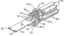
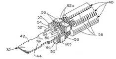
제3도는 본 발명을 사용하기 위해 제공된 동축 케이블 중 하나를 강성 슬리브 중 하나와 함께 도시한 사시도.3 is a perspective view of one of the coaxial cables provided for use with the present invention, with one of the rigid sleeves.
제4도는 케이블의 금속 차폐부와 유전체 사이에 강성 슬리브가 삽입된 제3도의 동축 케이블을 도시한 사시도.4 is a perspective view of the coaxial cable of FIG. 3 with a rigid sleeve inserted between the metal shield of the cable and the dielectric.
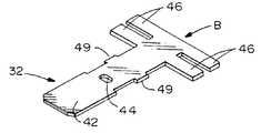
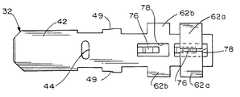
제5도는 접속 부재 또는 접지판이 형성되게 되는 스탬핑된 금속 블랭크의 사시도.5 is a perspective view of a stamped metal blank on which a connecting member or ground plate is to be formed.
제6도는 크림프 아암이 예비 또는 개방 위치로 성형된 접지판 및 강성 슬리브들이 삽입되어 있는 다수의 동축 케이블을 함께 도시한 사시도.FIG. 6 is a perspective view of a number of coaxial cables with a ground plate and rigid sleeves inserted with crimp arms molded into a preliminary or open position. FIG.
제7도는 제6도와 유사하나, 접지판의 크림프 아암들에 대하여 적절하게 위치한 동축 케이블을 도시한 사시도.7 is a perspective view similar to FIG. 6 but showing a coaxial cable properly positioned relative to the crimp arms of the ground plane.
제8도는 제7도와 유사하나 크림프 아암들이 크림핑되어 케이블의 금속 차폐부에 결합된 것을 도시한 사시도.FIG. 8 is similar to FIG. 7 but shows a crimp arms that are crimped and joined to the metal shield of the cable.
제9도는 제2도에 도시된 단자 모듈에 조립된 제8도의 부조립체의 사시도.9 is a perspective view of the subassembly of FIG. 8 assembled to the terminal module shown in FIG.
제10도는 본 발명의 다른 실시예의 일체형 이중 슬리브 부재의 사시도.10 is a perspective view of an integrated double sleeve member of another embodiment of the present invention.
제11도는 제10도의 일체형 이중 슬리브 부재와 함께 사용되는 접지판의 측면도.FIG. 11 is a side view of a ground plate for use with the unitary dual sleeve member of FIG. 10. FIG.
제12도는 제11도의 접지판의 평면도.12 is a plan view of the ground plate of FIG.
제13도는 네 개의 동축 케이블의 유전체에 주위에 설치된 제2도의 한 쌍의 일체형 이중 슬리브 부재의 단부도.13 is an end view of the pair of unitary dual sleeve members of FIG. 2 installed around the dielectric of the four coaxial cables.
제14도는 제13도와 유사하나, 이중 슬리브 부재 주위로 위치된 동축 케이블의 금속 브레이드를 도시하는 도면.FIG. 14 is a view similar to FIG. 13 but showing a metal braid of coaxial cable positioned around the double sleeve member.
제15도는 제14도와 유사하나, 접지판의 크림프 아암 내에 삽입된 이중 슬리브 부재 및 동축 케이블을 도시하는 도면.FIG. 15 is a view similar to FIG. 14 but showing a double sleeve member and a coaxial cable inserted in the crimp arm of the ground plate.
제16도는 제15도와 유사하나, 크림프 아암이 성형되어 금속 차폐부와 크림핑 결합된 것을 도시하는 도면.FIG. 16 is similar to FIG. 15, but shows that the crimp arm is molded and crimped with the metal shield.
* 도면의 주요부분에 대한 부호의 설명* Explanation of symbols for main parts of the drawings
10 : 전기 커넥터 12 : 유전체 하우징10
14 : 데이타 전송 단자 16 : 도전성 차폐부14 data transfer terminal 16 conductive shield
30a, 30b : 단자 블록 32 : 접지판 (접속 부재 또는 단자)30a, 30b: Terminal block 32: Ground plate (connection member or terminal)
34 : 포스트 38 : 신호 단자34: post 38: signal terminal
40 : 동축 케이블 42 : 블레이드부 (접지부)40: coaxial cable 42: blade portion (grounding portion)
50 : 슬리브 52 : 중심 도체50: sleeve 52: center conductor
54 : 내부 유전체 56 : 금속 차폐부54: internal dielectric 56: metal shield
58 : 절연 재킷 62a, 62b : 크림프 아암58:
본 발명의 새로운 특징은 청구범위에 기재되어 있다. 본 발명과 그 목적 및 장점에 대해서는 유사한 부분에는 유사한 부호를 병기한 첨부도면을 참조한 이후의 상세한 설명으로부터 명확하게 이해할 수 있다.New features of the invention are described in the claims. The present invention and its objects and advantages can be clearly understood from the following detailed description with reference to the accompanying drawings in which like parts bear like reference numerals.
도면중 제1도 및 제2도에서, 본 발명은 저속 데이터 전송 라인의 도체 및 고속 또는 고주파 전송 라인의 도체의 양자를 접속하기 위한 하이브리드 전기 커넥터인 차폐된 전기 커넥터(10)로 실시되어 있다. 특히, 전기 커넥터(10)는 다수의 데이타 전송 단자 (14, 제1도)를 장착하고 있는 유전체 하우징(12, 제2도)을 포함한다. 도전성 차폐부 (16)는 유전체 하우징(12)을 전체적으로 둘러싸고, 데이타 전송 단자(14)의 정합 단들 주위에서 전방으로 돌출하는 시라우드부(18)를 갖는다. 1994년 10월 25일자 미국 특허 제5,358,428호에 도시된 것과 실질적으로 일치하는 2편 후방쉘(도시 생략)은 하우징(12) 및 차폐부(16) 후방으로 돌출한다. 오버몰드된 부트(20)는 데이타 전송 라인 및 고속 또는 고주파 전송 라인의 양자를 포함하는 복합 전기 케이블(24)에 결합된 일체형 케이블 변형 완화부(22)를 포함한다. 한 쌍의 나사(26, thumb screw)는 오버몰딩된 부트를 통해서 돌출하고, 상호 결합 커넥터, 패널 또는 다른 구조물에 커넥터를 고정하기 위하여 외부에 나사형성된 전방 말단부(26a)를 포함한다.1 and 2 in the drawings, the invention is implemented with a shielded
제2도에 도시된 것처럼, 고속 신호 전송 단자 모듈(30)은 유전체 하우징(12)의 통로(31) 안에 그 후방으로부터 삽입된다. 이 단자 모듈은 사이에 접지판(32)을 클램핑하고 있는 한 쌍의 단자 블록(30a, 30b)을 포함한다. 각 단자 블록은 포스트(34) 및 리세스를 포함한다. 각 단자 블록으로부터의 포스트는 각 단자 블록으로부터 접지판의 구멍 또는 슬롯(44, 제5도)을 통해서 다른 단자 블록의 리세스로 연장되어 단자 블록 (30a, 30b)을 접지판(32)에 고정시켜 부조립체를 형성한다. 부조립체가 제2도에 도시된 것처럼 하우징(12)의 통로(31) 안에 일단 삽입되면 단자 블록들이 사이에 접지판을 클램핑한다. 단자 모듈은 각 단자 블록 상에 있는 램프식 래치(36, ramped latch)들에 의해 유전체 하우징 내에 유지된다.As shown in FIG. 2, the high speed signal
각 단자 블록(30a, 30b)은 적어도 하나의 고속 신호 단자(38) 주위에 오버몰딩된다. 한 쌍의 단자(38)의 접점단들은 접지판(32)의 전방단과 함께 차폐부(16)의 주변 시라우드부(18) 내에서 제1도의 커넥터의 전방으로 돌출하는 것으로 도시되어 있다. 단자(38, 제9도)의 후방단(38a)들은 제2도에 도시된 다수의 동축 케이블(40)의 중심 도체/코어(52)에 접속된다. 본 발명은 나중에 설명하는 것처럼 특히 동축 케이블의 금속 차폐부(56)를 접지판(32)에 접속하는 방법에 관한 것이다.Each
특히, 제5도는 도전성 금속 시트 재료로부터 스탬핑된 블랭크(B)를 도시하며, 이로부터 접지판(32)이 형성된다. 블랭크(B)는 대체로 T형이며, 접지판(32)용 블레이드부를 형성하게 되는 레그 또는 스템 부분(42)을 포함한다. 블레이드부는 단자 블록 (30a, 30b)의 포스트(34, 제2도)들이 연장되게 되는 구멍(44)을 포함한다. 한 쌍의 날개부 또는 아암(46)은 각 대향 엣지에 있는 레그(42)의 일단에서 외향 돌출한다. 이들 날개부는 나중에 설명하는 것처럼 접지판의 크림프 아암을 형성하게 된다. 최종적으로, 가시 또는 치(49)가 블레이드부(42)의 대향 엣지에 스탬핑되어 하우징 내에 단자 블록(30a, 30b) 및 접지판의 부조립체를 지지하는 것을 용이하게 한다.In particular, FIG. 5 shows a blank B stamped from a conductive metal sheet material, from which a
제3도 및 제4도는 본 발명의 단자 시스템과 함께 사용하도록 제공된 동축 케이블(40) 및 강성 원통형 슬리브(50)를 도시한다. 이 때, 각 동축 케이블(40)은 각 케이블이 튜브형 내부 유전체(54)에 의해 둘러싸인 중심 도체 또는 코어(52)를 포함하는 종래의 구조이다. 튜브형 금속 브레이드(56) 형태의 금속 차폐부는 내부 유전체(54)를 둘러싼다. 플라스틱 등의 절연 재킷(58)이 금속 브레이드(56)를 둘러싸서 전체 복합 동축 케이블(40)을 형성한다.3 and 4 show
본 발명에 따르면, 제4도에서 도시된 바와 같이 전단부가 내부 유전체(54)의 전방과 대체로 같은 높이가 되는 위치에 강성 슬리브가 도달할 때까지 강성 슬리브(50)는 동축 케이블(40)의 유전체(54)와 금속 차폐부(56) 사이의 위치로 화살표 "A" 방향 (제3도)으로 삽입 가능하다. 중심 도체/코어(52)는 접속을 위해 슬리브 및 내부 유전체의 종방향 외향으로 돌출된다. 슬리브는 강성 금속 재질로 제조될 수도 있다. 즉, 강성 슬리브는 후술되는 외부 크림핑 또는 클램핑력으로부터 유전체(54)를 보호한다.According to the invention, the
제6도는 날개부(46, 제5도)가 한 쌍의 상부 크림프 아암(62a) 및 한 쌍의 하부 크림프 아암(62b)을 형성하도록 내향으로 굽혀진 제5도의 스탬핑된 블랭크(B)를 도시한다. 즉, 접지판(32)에는 한 쌍의 동축 케이블에 클램핑을 위해 판의 대향 엣지에서 한 쌍의 대향된 크림프 아암이 제공되어, 판의 각 대향 측면에 한 쌍의 대향 크림프 아암들을 제공한다. 한 쌍(62a)은 블레이드부(42)의 가장 후방 말단부에 위치되며, 다른 한 쌍(62b)은 제1쌍의 종방향 전방으로 약간 이격되어 위치된다. 이러한 구조에서, 접지판은 커넥터의 사양에 따라 하나에서부터 네 개까지의 동축 케이블로부터 접속된다. 컴퓨터 장치에서, 세 개의 케이블이 모니터용으로 적색, 녹색, 및 청색 기호(signal)를 갖도록 사용될 수도 있다. 네번째 케이블은 픽셀 클록 타이밍 신호(pixel clock timing signal)를 수반하는 평면 스크린 모니터용으로 사용될 수도 있다. 제6도은 예시를 위해 제3도에서 도시된 바와 같이 각각 준비되고 제4도에서 도시된 바와 같이 강성 슬리브 (50)가 각 케이블의 내부 유전체와 금속 차폐부 사이에 삽입된 세 개의 동축 케이블 (40)을 도시한다.FIG. 6 shows the stamped blank B of FIG. 5 bent inwardly such that the
제7도는 금속 차폐부(56) 및 아래의 강성 슬리브(50)가 크림프 아암(62a, 62b)과 일치 또는 정렬된 위치로 이동된 동축 케이블(40)을 도시한다. 크림프 아암은 접지판(32)의 블레이드부(42)에 대해 동축 케이블을 적절히 위치시키는 기능을 한다. 크림프 아암은 제7도의 임시(preliminary or preformed) 위치에 도시되어 있다.FIG. 7 shows
단자 모듈을 처리하는 다음 단계는 크림프 아암(62a, 62b)을 크림핑 또는 성형하여 제8도에서 도시된 바와 같이 강성 슬리브(50) 외부의 노출된 금속 차폐부(56)에 대해 동축 케이블을 클램핑 결합하는 단계이다. 크림프 아암은 강성 슬리브(50)가 금속 차폐부를 받치면서 차폐부와 아암 사이가 양호하게 전기 접속될 정도의 충분한 힘으로 금속 차폐부(56)에 클램핑된다. 즉, 슬리브는 클램핑력에 대한 앤빌로서 기능한다. 강성 슬리브는 내부 유전체(54)가 크림프 아암(62a, 62b)에 의해 파손되거나 또는 손상되는 것을 방지한다.The next step of processing the terminal module is to crimp or mold the
일반 제8도의 부조립체가 제조되면, 이러한 부조립체는 블록(30a, 30b) 및 고속 신호 전송 단자(38)를 접속하도록 조립되어 제9도에서 도시되고 제2도에 대해 설명된 바와 같이 단자 모듈(30)을 형성한다. 동축 케이블의 중심 도체/코어(52)는 단자 (38)의 내단부(38a)에 납땜에 의해 제2도에서 도시되고 상술된 바와 같이 사이에 접지판(32)의 블레이드부(42)를 클램핑하는 단자 블록(30a, 30b)과 연결된다. 그 후, 단자 모듈은 제2도에서 도시된 바와 같이 유전체 하우징(12)내에 장착된다.Once the subassembly of FIG. 8 is manufactured, this subassembly is assembled to connect the
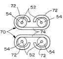
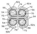
제10도 내지 제16도는 접지판(32)의 각 측면 상의 한 쌍의 강성 슬리브가 제10도의 일체형 이중 슬리브 부재(70, unitary dual-sleeve member)에 의해 대체된 본 발명의 다른 실시예를 도시한다. 각 일체형 이중 슬리브 부재는 웨브(74)에 의해 연결된 한 쌍의 원통형 슬리브부(72)를 포함한다.10-16 show another embodiment of the invention in which a pair of rigid sleeves on each side of the
제11도 및 제12도는 접지판의 블레이드부(42)의 각 개부(78)로부터 스탬핑 성형된 한 쌍의 스프링 클립(76)이 추가된다는 점만이 다른 상술된 접지판(32)을 도시한다. 제5도 내지 제9도의 접지판(32)에 대해 상술된 유사한 부품을 표시하기 위해 유사한 도면 부호가 제11도 및 제12도에 적용되었다. 스프링 클립은 이중 슬리브 부재(70)의 슬리브부(72) 사이의 웨브(74)를 결합하여 접지판의 블레이드부(70)의 표면에 부재를 지지하는 데 효과적이다. 즉, 결합면(76a, 제11도에서 가장 잘 도시됨)은 각 웨브(74)의 두께 보다 작은 양으로 블레이드부(42)의 각 인접 면으로부터 이격되어, 접지판의 블레이드부에 대해 웨브를, 따라서, 이중 슬리브 부재를 탄성 클램핑한다.11 and 12 show the
제13도는 슬리브부(72)가 네 개의 동축 케이블의 내부 유전체(54)에 대해 위치된 두 개의 일체형 이중 슬리브 부재(70)를 도시한다.FIG. 13 shows two unitary
제14도는 제13도와 유사하나, 두 개의 동축 케이블의 금속 차폐부(56)가 각 일체형 이중 슬리브 부재(70)의 슬리브부(72)에 대해 위치된 것을 도시한다. 금속 브레이드는 도면 부호 80에서 종방향으로 분할(slit)되어 슬리브부(72)가 차폐부 내부에 위치되면서 이중 슬리브 부재의 웨브(74)가 금속 브레이드 내로 활주될 수 있다.FIG. 14 is similar to FIG. 13 but shows that the
제15도는 미리 성형된 크림프 아암(62a, 62b) 내에 위치된 네 개의 동축 케이블 및 두 개의 일체형 이중 슬리브 부재(70)를 도시한다. 부조립체의 이러한 상태는 일반적으로 이중 슬리브 부재(70)가 스프링 클립(76)에 의해 위치에 지지된다는 점을 제외하고는 제7도에 대한 제1실시예의 상기 설명과 대응된다.15 shows four coaxial cables and two integral
최종적으로, 제16도은 각 이중 슬리브 부재(70)의 두 개의 슬리브부(72)가 금속 차폐부 뒤의 앤빌로서 작용하여 각 동축 케이블의 내부 유전체(54)를 보호하는, 네 개의 동축 케이블의 금속 차폐부(56)에 있는 크림프 아암(62a, 62b)을 도시한다. 본 발명의 제2실시예의 설명은 제8도에 대한 제1실시예의 상술된 설명에 일반적으로 대응한다.Finally, FIG. 16 shows the four coaxial cable metals in which two
본 발명의 개념이 접지판(42) 형태로 접속 부재(32)에 동축 케이블의 금속 차폐부를 접속시키는 것으로 본 명세서에서 도시되고 설명되었다. 그러나, 본 발명의 개념은 전기 단자 자체와 같은 다른 종류의 접속 부재에 금속 차폐부(56)를 접속시키기 위해서도 동일하게 적용될 수 있다.The concept of the present invention is shown and described herein as connecting the metal shield of the coaxial cable to the connecting
본 발명은 그 기술 사상 및 중심 특징 내에서 다른 특정 형태로도 실시할 수 있다. 따라서, 상기에 설명한 실시예들은 도시를 위한 것이지 제한적인 것이 아니며, 본 발명은 상기 설명 내용에 제한되지 않는다.The present invention can be embodied in other specific forms within the spirit and central features thereof. Accordingly, the embodiments described above are for illustration and not limitation, and the present invention is not limited to the above description.
Claims (33)
Translated fromKoreanApplications Claiming Priority (3)
| Application Number | Priority Date | Filing Date | Title |
|---|---|---|---|
| US08/609,301US5716236A (en) | 1996-03-01 | 1996-03-01 | System for terminating the shield of a high speed cable |
| US08/609,301 | 1996-03-01 | ||
| US8/609,301 | 1996-03-01 |
Publications (2)
| Publication Number | Publication Date |
|---|---|
| KR970068037A KR970068037A (en) | 1997-10-13 |
| KR100256927B1true KR100256927B1 (en) | 2000-05-15 |
Family
ID=24440203
Family Applications (1)
| Application Number | Title | Priority Date | Filing Date |
|---|---|---|---|
| KR1019970006843AExpired - Fee RelatedKR100256927B1 (en) | 1996-03-01 | 1997-02-28 | Shield connection system of high speed cable |
Country Status (8)
| Country | Link |
|---|---|
| US (1) | US5716236A (en) |
| EP (1) | EP0793297A3 (en) |
| JP (1) | JP3015938B2 (en) |
| KR (1) | KR100256927B1 (en) |
| CN (1) | CN1096130C (en) |
| IN (1) | IN191881B (en) |
| MY (1) | MY116858A (en) |
| TW (1) | TW326582B (en) |
Families Citing this family (36)
| Publication number | Priority date | Publication date | Assignee | Title |
|---|---|---|---|---|
| GB9712458D0 (en)* | 1997-06-17 | 1997-08-20 | Smiths Industries Plc | Electrical connection |
| US6287145B1 (en)* | 1998-11-06 | 2001-09-11 | Engineered Transitions Company, Inc. | Internal shield splice |
| US6454605B1 (en)* | 1999-07-16 | 2002-09-24 | Molex Incorporated | Impedance-tuned termination assembly and connectors incorporating same |
| US6280209B1 (en) | 1999-07-16 | 2001-08-28 | Molex Incorporated | Connector with improved performance characteristics |
| ATE278257T1 (en) | 1999-07-16 | 2004-10-15 | Molex Inc | IMPEDANCE MATCHED CONNECTOR |
| TW421314U (en)* | 1999-08-24 | 2001-02-01 | Hon Hai Prec Ind Co Ltd | Cable connector having a grounding device |
| TW539307U (en)* | 1999-08-24 | 2003-06-21 | Hon Hai Prec Ind Co Ltd | Plug connector |
| US6200163B1 (en) | 1999-08-30 | 2001-03-13 | Molex Incorporated | Electrical connector including means for terminating the shield of a high speed cable |
| US6186828B1 (en) | 1999-08-30 | 2001-02-13 | Molex Incorporated | Electrical connector including coaxial cable management system |
| JP3656187B2 (en)* | 2000-04-17 | 2005-06-08 | 日本航空電子工業株式会社 | Connector for shielded cable |
| USD453739S1 (en) | 2000-06-08 | 2002-02-19 | Ching-Yu Lin | Terminal for plug |
| JP3564555B2 (en)* | 2001-03-05 | 2004-09-15 | 日本航空電子工業株式会社 | High-speed differential signal transmission connector |
| DE10121762C1 (en) | 2001-05-04 | 2003-02-20 | Siemens Ag | Connector for connecting coaxial conductors |
| US7039417B2 (en) | 2003-09-25 | 2006-05-02 | Lenovo Pte Ltd | Apparatus, system, and method for mitigating access point data rate degradation |
| US6953351B2 (en) | 2002-06-21 | 2005-10-11 | Molex Incorporated | High-density, impedance-tuned connector having modular construction |
| US6863549B2 (en) | 2002-09-25 | 2005-03-08 | Molex Incorporated | Impedance-tuned terminal contact arrangement and connectors incorporating same |
| US6867362B2 (en)* | 2003-03-07 | 2005-03-15 | Hewlett-Packard Development Company, L.P. | Cable extension for reducing EMI emissions |
| US7771208B2 (en)* | 2004-12-16 | 2010-08-10 | International Business Machines Corporation | Metalized elastomeric electrical contacts |
| US20060137890A1 (en)* | 2004-12-28 | 2006-06-29 | International Business Machines Corporation | Apparatus and methods for unshielded twisted wire pair radiated emission suppression |
| JP4421505B2 (en)* | 2005-03-30 | 2010-02-24 | 本多通信工業株式会社 | Plug for connector with lock screw |
| US7228625B1 (en) | 2006-07-12 | 2007-06-12 | Yazaki North America, Inc. | Method for attaching an electrical cable to a connector shield |
| JP4720718B2 (en)* | 2006-10-31 | 2011-07-13 | 住友電装株式会社 | Shield connector |
| TWI446630B (en) | 2007-08-23 | 2014-07-21 | Molex Inc | Board mounted electrical connector |
| US7736185B2 (en)* | 2008-05-29 | 2010-06-15 | The Boeing Company | Connector shield termination in limited clearance installations |
| US7717733B1 (en)* | 2008-12-10 | 2010-05-18 | Hon Hai Precision Ind. Co., Ltd. | Cable assembly having enhanced interconnection device thereof |
| USD634273S1 (en) | 2010-08-30 | 2011-03-15 | Mattel, Inc. | Electrical terminal |
| JP5711571B2 (en)* | 2011-03-02 | 2015-05-07 | 矢崎総業株式会社 | Coaxial cable terminal processing structure and terminal processing method |
| CN103650256B (en) | 2011-07-07 | 2017-04-12 | 莫列斯公司 | Bracket for termination-multi-wire cable and cable connector |
| US9362684B2 (en)* | 2011-12-14 | 2016-06-07 | Intel Corporation | Rate scalable connector for high bandwidth consumer applications |
| DE102013110476A1 (en)* | 2013-09-23 | 2015-03-26 | Phoenix Contact Gmbh & Co. Kg | Cable lug device with current bar and connection terminal |
| JP6859198B2 (en)* | 2017-05-25 | 2021-04-14 | 日野自動車株式会社 | Heterogeneous shield connection method |
| CN109546823B (en)* | 2018-12-25 | 2024-12-24 | 嘉兴藤飞精工科技有限公司 | Automatic feeding mechanism for insulating sleeves for stator core winding machines |
| DE102019120373B4 (en)* | 2019-07-29 | 2025-09-18 | Phoenix Contact E-Mobility Gmbh | Connection arrangement and vehicle |
| JP7467127B2 (en) | 2020-01-17 | 2024-04-15 | 日本航空電子工業株式会社 | Cable assemblies and structures |
| CN116131034A (en)* | 2023-01-10 | 2023-05-16 | 立讯汽车技术(上海)有限公司 | Cable connector and manufacturing method thereof |
| JP2025000309A (en)* | 2023-06-19 | 2025-01-07 | 株式会社オートネットワーク技術研究所 | Terminal Module |
Family Cites Families (25)
| Publication number | Priority date | Publication date | Assignee | Title |
|---|---|---|---|---|
| US3383457A (en)* | 1966-04-05 | 1968-05-14 | Amp Inc | Connector means for connecting coaxial cable to a printed circuit board |
| US4451099A (en)* | 1982-05-07 | 1984-05-29 | Amp Incorporated | Electrical connector having commoning member |
| JPH031903Y2 (en)* | 1985-05-13 | 1991-01-21 | ||
| CA1279912C (en)* | 1986-10-15 | 1991-02-05 | Toshiaki Tokizane | High-frequency cable connector |
| US4767345A (en)* | 1987-03-27 | 1988-08-30 | Amp Incorporated | High-density, modular, electrical connector |
| DE3921990A1 (en)* | 1988-07-08 | 1990-01-11 | Yazaki Corp | PINCH CONNECTOR FOR LADDER AND METHOD FOR PRODUCING A PINCH CONNECTION |
| US4993968A (en)* | 1989-03-02 | 1991-02-19 | Precision Interconnect Corporation | Economical connector system for an array of conductors |
| US4921447A (en)* | 1989-05-17 | 1990-05-01 | Amp Incorporated | Terminating a shield of a malleable coaxial cable |
| JPH0734373B2 (en)* | 1989-11-15 | 1995-04-12 | ヒロセ電機株式会社 | connector |
| US4960392A (en)* | 1990-01-16 | 1990-10-02 | Dickie Robert G | Shielded connector assembly with noise suppressor |
| JPH0737261Y2 (en)* | 1990-08-30 | 1995-08-23 | ヒロセ電機株式会社 | Electrical connector |
| JPH0452368U (en)* | 1990-09-10 | 1992-05-01 | ||
| JPH0452370U (en)* | 1990-09-10 | 1992-05-01 | ||
| JPH0722054Y2 (en)* | 1990-09-11 | 1995-05-17 | ヒロセ電機株式会社 | Electrical connector |
| US5085596A (en)* | 1990-09-24 | 1992-02-04 | Molex Incorporated | Shielded electrical connector |
| US5115562A (en)* | 1990-09-24 | 1992-05-26 | Molex Incorporated | Method of making shielded electrical connector |
| NL9101695A (en)* | 1991-10-09 | 1993-05-03 | Burndy Electra Nv | CONTACT FOR A CABLE WITH ONE OR MORE INTERNAL CONDUCTORS. |
| US5180316A (en)* | 1991-03-25 | 1993-01-19 | Molex Incorporated | Shielded electrical connector |
| US5197904A (en)* | 1992-09-04 | 1993-03-30 | Michael Gold | Connector for coaxially shielded cables |
| US5222898A (en)* | 1992-10-01 | 1993-06-29 | The Whitaker Corporation | Modular cable assembly |
| US5415569A (en)* | 1992-10-19 | 1995-05-16 | Molex Incorporated | Filtered electrical connector assembly |
| US5304069A (en)* | 1993-07-22 | 1994-04-19 | Molex Incorporated | Grounding electrical connectors |
| NL9400321A (en)* | 1994-03-03 | 1995-10-02 | Framatome Connectors Belgium | Connector for a cable for high-frequency signals. |
| JPH0845575A (en)* | 1994-07-29 | 1996-02-16 | Sumitomo Wiring Syst Ltd | Terminal processing structure for shield wire and terminal processing method |
| US5509827A (en)* | 1994-11-21 | 1996-04-23 | Cray Computer Corporation | High density, high bandwidth, coaxial cable, flexible circuit and circuit board connection assembly |
- 1996
- 1996-03-01USUS08/609,301patent/US5716236A/ennot_activeExpired - Fee Related
- 1997
- 1997-02-18ININ294CA1997patent/IN191881B/enunknown
- 1997-02-21TWTW086102089Apatent/TW326582B/enactive
- 1997-02-27MYMYPI97000778Apatent/MY116858A/enunknown
- 1997-02-27EPEP97103226Apatent/EP0793297A3/ennot_activeWithdrawn
- 1997-02-28KRKR1019970006843Apatent/KR100256927B1/ennot_activeExpired - Fee Related
- 1997-02-28JPJP9062334Apatent/JP3015938B2/ennot_activeExpired - Fee Related
- 1997-02-28CNCN97110027Apatent/CN1096130C/ennot_activeExpired - Fee Related
Also Published As
| Publication number | Publication date |
|---|---|
| JP3015938B2 (en) | 2000-03-06 |
| EP0793297A3 (en) | 1998-11-25 |
| KR970068037A (en) | 1997-10-13 |
| EP0793297A2 (en) | 1997-09-03 |
| JPH09245899A (en) | 1997-09-19 |
| CN1168548A (en) | 1997-12-24 |
| TW326582B (en) | 1998-02-11 |
| CN1096130C (en) | 2002-12-11 |
| MX9701558A (en) | 1997-09-30 |
| MY116858A (en) | 2004-04-30 |
| US5716236A (en) | 1998-02-10 |
| IN191881B (en) | 2004-01-10 |
Similar Documents
| Publication | Publication Date | Title |
|---|---|---|
| KR100256927B1 (en) | Shield connection system of high speed cable | |
| KR100282630B1 (en) | Shield connection system of high speed cable | |
| KR100282631B1 (en) | System for Terminating the Shield of a High Speed Cable | |
| US5725387A (en) | System for terminating the shield of a high speed cable | |
| US5718607A (en) | System for terminating the shield of a high speed cable | |
| US5961348A (en) | System for terminating the shield of a high speed cable | |
| US5785555A (en) | System for terminating the shield of a high speed cable | |
| US20060234556A1 (en) | Connector assembly | |
| EP1436863A1 (en) | Connector with improved grounding means | |
| MXPA97001560A (en) | System to complete the protection of a cable dealta veloci | |
| KR100256928B1 (en) | System for terminating high speed cable shields | |
| US5203079A (en) | Method of terminating miniature coaxial electrical connector | |
| US20100065327A1 (en) | Cable assembly with molded grounding bar and method of making same | |
| KR100282632B1 (en) | System for terminating high speed cable shields | |
| JPH10189120A (en) | Multi-pole shielded cable plug | |
| MXPA97001563A (en) | System to complete the shield of a high speed cable | |
| MXPA97001559A (en) | System for the termination of the protection of a high speed cable | |
| MXPA97001558A (en) | System to complete the shield of a cable dealta veloci | |
| MXPA97001557A (en) | System for the termination of the protection of a high speed cable |
Legal Events
| Date | Code | Title | Description |
|---|---|---|---|
| A201 | Request for examination | ||
| PA0109 | Patent application | St.27 status event code:A-0-1-A10-A12-nap-PA0109 | |
| PA0201 | Request for examination | St.27 status event code:A-1-2-D10-D11-exm-PA0201 | |
| R17-X000 | Change to representative recorded | St.27 status event code:A-3-3-R10-R17-oth-X000 | |
| PG1501 | Laying open of application | St.27 status event code:A-1-1-Q10-Q12-nap-PG1501 | |
| E701 | Decision to grant or registration of patent right | ||
| PE0701 | Decision of registration | St.27 status event code:A-1-2-D10-D22-exm-PE0701 | |
| GRNT | Written decision to grant | ||
| PR0701 | Registration of establishment | St.27 status event code:A-2-4-F10-F11-exm-PR0701 | |
| PR1002 | Payment of registration fee | Fee payment year number:1 St.27 status event code:A-2-2-U10-U11-oth-PR1002 | |
| PG1601 | Publication of registration | St.27 status event code:A-4-4-Q10-Q13-nap-PG1601 | |
| PR1001 | Payment of annual fee | Fee payment year number:4 St.27 status event code:A-4-4-U10-U11-oth-PR1001 | |
| FPAY | Annual fee payment | Payment date:20040112 Year of fee payment:5 | |
| PR1001 | Payment of annual fee | Fee payment year number:5 St.27 status event code:A-4-4-U10-U11-oth-PR1001 | |
| LAPS | Lapse due to unpaid annual fee | ||
| PC1903 | Unpaid annual fee | Not in force date:20050226 Payment event data comment text:Termination Category : DEFAULT_OF_REGISTRATION_FEE St.27 status event code:A-4-4-U10-U13-oth-PC1903 | |
| PC1903 | Unpaid annual fee | Ip right cessation event data comment text:Termination Category : DEFAULT_OF_REGISTRATION_FEE Not in force date:20050226 St.27 status event code:N-4-6-H10-H13-oth-PC1903 | |
| PN2301 | Change of applicant | St.27 status event code:A-5-5-R10-R11-asn-PN2301 St.27 status event code:A-5-5-R10-R13-asn-PN2301 | |
| R18-X000 | Changes to party contact information recorded | St.27 status event code:A-5-5-R10-R18-oth-X000 |