KR100254856B1 - Liquid crystal display element - Google Patents
Liquid crystal display elementDownload PDFInfo
- Publication number
- KR100254856B1 KR100254856B1KR1019970022108AKR19970022108AKR100254856B1KR 100254856 B1KR100254856 B1KR 100254856B1KR 1019970022108 AKR1019970022108 AKR 1019970022108AKR 19970022108 AKR19970022108 AKR 19970022108AKR 100254856 B1KR100254856 B1KR 100254856B1
- Authority
- KR
- South Korea
- Prior art keywords
- liquid crystal
- crystal display
- molecules
- display device
- lower substrates
- Prior art date
- Legal status (The legal status is an assumption and is not a legal conclusion. Google has not performed a legal analysis and makes no representation as to the accuracy of the status listed.)
- Expired - Lifetime
Links
- 239000004973liquid crystal related substanceSubstances0.000titleclaimsabstractdescription128
- 239000000758substrateSubstances0.000claimsabstractdescription75
- 230000005684electric fieldEffects0.000claimsdescription32
- 230000010287polarizationEffects0.000claimsdescription11
- 239000002019doping agentSubstances0.000claimsdescription3
- 239000010408filmSubstances0.000description11
- 238000000034methodMethods0.000description8
- 230000009977dual effectEffects0.000description7
- 238000002834transmittanceMethods0.000description7
- 238000010586diagramMethods0.000description3
- 239000011159matrix materialSubstances0.000description3
- 230000015572biosynthetic processEffects0.000description2
- 230000000694effectsEffects0.000description2
- 230000003287optical effectEffects0.000description2
- 238000000206photolithographyMethods0.000description2
- 239000010409thin filmSubstances0.000description2
- VYZAMTAEIAYCRO-UHFFFAOYSA-NChromiumChemical compound[Cr]VYZAMTAEIAYCRO-UHFFFAOYSA-N0.000description1
- 229910052782aluminiumInorganic materials0.000description1
- XAGFODPZIPBFFR-UHFFFAOYSA-NaluminiumChemical compound[Al]XAGFODPZIPBFFR-UHFFFAOYSA-N0.000description1
- 229910052804chromiumInorganic materials0.000description1
- 239000011651chromiumSubstances0.000description1
- 239000000463materialSubstances0.000description1
- 239000007769metal materialSubstances0.000description1
- 238000004088simulationMethods0.000description1
Images


Classifications
- G—PHYSICS
- G02—OPTICS
- G02F—OPTICAL DEVICES OR ARRANGEMENTS FOR THE CONTROL OF LIGHT BY MODIFICATION OF THE OPTICAL PROPERTIES OF THE MEDIA OF THE ELEMENTS INVOLVED THEREIN; NON-LINEAR OPTICS; FREQUENCY-CHANGING OF LIGHT; OPTICAL LOGIC ELEMENTS; OPTICAL ANALOGUE/DIGITAL CONVERTERS
- G02F1/00—Devices or arrangements for the control of the intensity, colour, phase, polarisation or direction of light arriving from an independent light source, e.g. switching, gating or modulating; Non-linear optics
- G02F1/01—Devices or arrangements for the control of the intensity, colour, phase, polarisation or direction of light arriving from an independent light source, e.g. switching, gating or modulating; Non-linear optics for the control of the intensity, phase, polarisation or colour
- G02F1/13—Devices or arrangements for the control of the intensity, colour, phase, polarisation or direction of light arriving from an independent light source, e.g. switching, gating or modulating; Non-linear optics for the control of the intensity, phase, polarisation or colour based on liquid crystals, e.g. single liquid crystal display cells
- G02F1/133—Constructional arrangements; Operation of liquid crystal cells; Circuit arrangements
- G02F1/1333—Constructional arrangements; Manufacturing methods
- G02F1/1343—Electrodes
- G02F1/134309—Electrodes characterised by their geometrical arrangement
- G02F1/134363—Electrodes characterised by their geometrical arrangement for applying an electric field parallel to the substrate, i.e. in-plane switching [IPS]
- G—PHYSICS
- G02—OPTICS
- G02F—OPTICAL DEVICES OR ARRANGEMENTS FOR THE CONTROL OF LIGHT BY MODIFICATION OF THE OPTICAL PROPERTIES OF THE MEDIA OF THE ELEMENTS INVOLVED THEREIN; NON-LINEAR OPTICS; FREQUENCY-CHANGING OF LIGHT; OPTICAL LOGIC ELEMENTS; OPTICAL ANALOGUE/DIGITAL CONVERTERS
- G02F1/00—Devices or arrangements for the control of the intensity, colour, phase, polarisation or direction of light arriving from an independent light source, e.g. switching, gating or modulating; Non-linear optics
- G02F1/01—Devices or arrangements for the control of the intensity, colour, phase, polarisation or direction of light arriving from an independent light source, e.g. switching, gating or modulating; Non-linear optics for the control of the intensity, phase, polarisation or colour
- G02F1/13—Devices or arrangements for the control of the intensity, colour, phase, polarisation or direction of light arriving from an independent light source, e.g. switching, gating or modulating; Non-linear optics for the control of the intensity, phase, polarisation or colour based on liquid crystals, e.g. single liquid crystal display cells
- G02F1/133—Constructional arrangements; Operation of liquid crystal cells; Circuit arrangements
- G02F1/1333—Constructional arrangements; Manufacturing methods
- G02F1/1335—Structural association of cells with optical devices, e.g. polarisers or reflectors
- G—PHYSICS
- G02—OPTICS
- G02F—OPTICAL DEVICES OR ARRANGEMENTS FOR THE CONTROL OF LIGHT BY MODIFICATION OF THE OPTICAL PROPERTIES OF THE MEDIA OF THE ELEMENTS INVOLVED THEREIN; NON-LINEAR OPTICS; FREQUENCY-CHANGING OF LIGHT; OPTICAL LOGIC ELEMENTS; OPTICAL ANALOGUE/DIGITAL CONVERTERS
- G02F1/00—Devices or arrangements for the control of the intensity, colour, phase, polarisation or direction of light arriving from an independent light source, e.g. switching, gating or modulating; Non-linear optics
- G02F1/01—Devices or arrangements for the control of the intensity, colour, phase, polarisation or direction of light arriving from an independent light source, e.g. switching, gating or modulating; Non-linear optics for the control of the intensity, phase, polarisation or colour
- G02F1/13—Devices or arrangements for the control of the intensity, colour, phase, polarisation or direction of light arriving from an independent light source, e.g. switching, gating or modulating; Non-linear optics for the control of the intensity, phase, polarisation or colour based on liquid crystals, e.g. single liquid crystal display cells
- G02F1/133—Constructional arrangements; Operation of liquid crystal cells; Circuit arrangements
- G02F1/1333—Constructional arrangements; Manufacturing methods
- G02F1/1337—Surface-induced orientation of the liquid crystal molecules, e.g. by alignment layers
- G02F1/133742—Surface-induced orientation of the liquid crystal molecules, e.g. by alignment layers for homeotropic alignment
Landscapes
- Physics & Mathematics (AREA)
- Nonlinear Science (AREA)
- Mathematical Physics (AREA)
- Chemical & Material Sciences (AREA)
- Crystallography & Structural Chemistry (AREA)
- General Physics & Mathematics (AREA)
- Optics & Photonics (AREA)
- Geometry (AREA)
- Liquid Crystal (AREA)
Abstract
Translated fromKoreanDescription
Translated fromKorean본 발명은 액정 표시 소자에 관한 것으로, 보다 구체적으로는, 대향하는 상.하부 기판과, 이 기판들 사이에 개재되는 액정을 포함하는 액정 표시 소장에 관한 것이다.BACKGROUND OF THE
일반적으로, 액정 표시 소자는 텔레비젼, 그래픽 디스플레이등의 표시소자를 구성한다. 특히 액티브 매트릭스형의 액정 표시 소자는 고속 응답 특성을 갖으며, 높은 화소수에 적합하여 디스플레이 화면의 고화질화, 대형화, 컬러 화면화등을 실현하는데 크게 기여하고 있다.Generally, a liquid crystal display element constitutes display elements, such as a television and a graphic display. In particular, the active matrix type liquid crystal display device has high-speed response characteristics and is suitable for a high number of pixels, thereby greatly contributing to realizing high quality, large size, color screen, and the like of a display screen.
현재의 액정 표시 소자는 넓은 시야각과, 좌우 위상차 대칭 여부가 그 특성을 가늠하는데 주요한 요소가 된다. 이러한 요구를 만족시키기 위하여, 공정자는 넓은 시야각을 얻음은 물론 좌우 시야각이 대칭을 이루는 액정 표시 소자를 개발하는데 주력하고 있다.In the current liquid crystal display device, a wide viewing angle and symmetry of the left and right phase differences become a major factor in determining its characteristics. In order to satisfy such demands, the processman is focusing on developing a liquid crystal display device having a wide viewing angle as well as symmetrical left and right viewing angles.
그 중 넓은 시야각과 좌우 위상차의 대칭을 위하여, 후지쯔사에서 이중 ECB 모드(dual electrically controlled birefringence mode)가 개발되었다.Among them, Fujitsu has developed a dual electrically controlled birefringence mode for wide viewing angle and symmetry of phase difference.
이 이중 ECB 모드는 제1(a)도에 도시된 바와 같이, 대향하는 하부 및 상부 기판(1,2)과, 이 기판들(1,2) 사이에 개재되는 액정(3) 및 기판들(1,2)의 액정(3) 대향면에 액정을 일정한 방향으로 배열시키기 위한 배향막(1a, 2a) 예를들어, 액정 분자의 장축이 기판면과 수직이 되도록 배열시키는 수직 배향막이 구비된다. 또한, 액정(3)은 예를들어, 유전율 이방성이 음인 물질이 이용된다. 이때, 하부 기판(1)과 상부 기판(2)에는 액정을 구동시키기 위한 전극들이 각각 구비되어, 이후 전계 인가시 기판면에 수직인 전계가 형성되도록 한다.This dual ECB mode is characterized by opposing lower and
여기서, 배향막(1a, 2a)은 이후에 전계 인가시, 기판(1,2) 사이의 중앙 부분에 존재하는 액정이 소정의 축을 중심으로 대칭을 이룰수 있도록 러빙처리가 되어 있다. 즉, 배향막(1a, 2a)은 좌우 시야각을 개선하기 위하여 단위 화소내에 이중 도메인(D1, D2)이 형성되도록, 공지의 포토리소그라피 공정 또는 광 배향 공정 등에 의하여 러빙처리된다. 여기서, 도메인이란 액정 분자들이 동일방향으로 배열되는 그룹으로서, 이중 도메인은 하나의 단위 화소 공간에 액정 분자들이 대칭되는 두 방향으로 배열된 것을 말한다.Here, the
이러한 구성을 갖는 ECB 모드의 액정 표시 소자는 전계 인가시, 배향막의 영향으로, 액정(3)내 분자들은 기판(1,2) 표면에 수직으로 배열된다. 이에따라, 하부 기판(1)의 뒷면으로부터 입사되는 빛은 선광성을 잃어, 빛이 차단된다.In the ECB mode liquid crystal display device having such a configuration, when the electric field is applied, the molecules in the
한편, 이 액정 표시 소자에 소정 전압이 인가되면, 기판들(1,2)에 수직인 형태의 전계가 형성되고, 액정(3)내의 분자들은 제1(b)도에 도시한 바와 같이 기판측에서는 액정 분자들이 기판에 수직으로 배열되고, 중앙 부근에는 전계와 액정 분자의 장축이 직교를 이룰수 있도록 소정 각도만큼 틀어진다. 이때, 배향막(1a, 2a)에 2중 도메인이 형성되도록 서로 다른 방향으로 러빙되어 있어, 액정내 중앙에 있는 액정 분자들은 좌우 대칭을 이루면서 배열된다. 이에따라, 하부 기판(1) 뒷면으로부터 입사되는 빛은 액정을 통과하면서 위상이 변화되어, 상부 기판(2)을 통과한다. 이때, 단위 화소내의 액정 분자들은 서로 대칭적으로 배열되므로, 액정 분자의 굴절율 이방성이 보상된다. 따라서, 좌우 시야각이 개선되는 효과가 있다.On the other hand, when a predetermined voltage is applied to the liquid crystal display element, an electric field in a form perpendicular to the
본 도면에서는 편광판이 도시되지 않았지만, 기판들(1,2) 뒷면에 설치되어 있다.Although the polarizers are not shown in this drawing, the polarizers are provided on the rear surfaces of the
그러나, 상기와 같은 이중 ECB 모드는 단위 화소내에 이중 도메인이 형성되도록, 적어도 2번의 포토리소그라피 공정을 이용한 러빙 또는 광 배향 등의 공정이 진행되어야 하므로 공정이 번거로와진다. 더욱이, 2번의 러빙 공정으로 배향막 및 배향막 하부에 형성된 박막 트랜지스터(도시되지 않음)에 손상을 가할 수 있다. 과존재하는 소자를 파괴할 수 있는 문제점이 존재한다.However, in the dual ECB mode as described above, a process such as rubbing or photo alignment using at least two photolithography processes has to be performed so that the dual domain is formed in the unit pixel. Furthermore, two rubbing processes may damage the alignment film and the thin film transistor (not shown) formed under the alignment film. There is a problem that can destroy an existing device.
더욱이, 상하 기판 사이에 전계가 형성되기 이전, 액정 분자들은 수직 배항막의 영향으로 기판에 수직으로 배열되어 있으므로, 정면에서의 시야각은 우수하나, 측면에서는 액정 분자의 굴절율 이방성으로 인하여, 광 누설이 발생된다.Furthermore, before the electric field is formed between the upper and lower substrates, since the liquid crystal molecules are arranged perpendicular to the substrate under the influence of the vertical locating film, the viewing angle at the front is excellent, but light leakage occurs due to the refractive anisotropy of the liquid crystal molecules at the side. do.
따라서, 본 발명의 목적은 여러번의 러빙 공정에 의한 도메인 형성없이도, 액정 분자들을 좌우 대칭이 되도록 구동시킬 수 있는 액정 표시 소자를 제공하는 것이다.Accordingly, an object of the present invention is to provide a liquid crystal display device capable of driving liquid crystal molecules to be symmetrical without domain formation by multiple rubbing processes.
또한, 본 발명의 다른 목적은, 전계 인가전에 어느면에서나 완전한 다크를 이룰수 있는 액정 표시 소자를 제공하는 것이다.Another object of the present invention is to provide a liquid crystal display device capable of achieving a completely dark color on either side before applying an electric field.
제1(a)도 및 제1(b)도는 종래의 이중 ECB 모드의 액정 표시 소자의 단면도.1 (a) and 1 (b) are cross-sectional views of a liquid crystal display device of the conventional dual ECB mode.
제2(a)도 및 제2(b)도는 본 발명에 따른 액정 표시 소자의 단면도.2 (a) and 2 (b) are cross-sectional views of the liquid crystal display device according to the present invention.
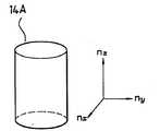
제3(a)도는 원통형의 액정 분자를 나타낸 도면.3 (a) is a diagram showing a cylindrical liquid crystal molecule.
제3(b)도는 위상 보정판을 이루는 디스크 타입의 액정 분자를 나타낸 도면.FIG. 3 (b) shows disk type liquid crystal molecules constituting a phase correction plate. FIG.
제4도는 본 발명의 액정 표시 소자를 시뮬레이션 한 결과를 나타낸 도면.4 is a diagram showing the results of a simulation of the liquid crystal display of the present invention.
* 도면의 주요부분에 대한 부호의 설명* Explanation of symbols for main parts of the drawings
10 : 하부 기판 11 : 화소 전극10
12 : 카운터 전극 13, 16 : 배향막12
14 : 액정 17A, 17B : 편광판14
18 : 위상 보정판18: phase correction plate
상기한 본 발명의 목적을 달성하기 위하여, 본 발명은, 대향하는 상.하부 기판; 상기 상.하부 기판 사이에 협지된 액정; 상기 액정내 분자들을 타원 형태로 구동시키기 위하여 하부 기판 상에 이격 배치된 화소 전극과 카운터 전극/ 상기 상.하부 기판의 액정 대향면 각각에 형성되는 배향막; 상기 상.하부 기판의 뒷면에 각각 설치되며, 빛을 일방향으로 편향시키는 상.하 편광판; 상기 상부 기판과 상부 편광판 사이에 개재되어, 액정 분자들을 등방성화하는 위상 보정판을 포함한다.In order to achieve the above object of the present invention, the present invention, the upper and lower substrates; A liquid crystal sandwiched between the upper and lower substrates; A pixel electrode and a counter electrode spaced apart from each other on the lower substrate so as to drive the molecules in the liquid crystal in an elliptic shape; an alignment layer formed on each of the liquid crystal facing surfaces of the upper and lower substrates; Upper and lower polarizers respectively installed on the rear surfaces of the upper and lower substrates and deflecting light in one direction; And a phase correction plate interposed between the upper substrate and the upper polarizer to isotropicize liquid crystal molecules.
또한, 본 발명은, 대향하는 상.하부 기판; 상기 상.하부 기판 사이에 협지된 유전율 이방성이 양인 액정; 상기 액정내의 분자들을 타원 형태로 구동시키기 위한 하부 기판 상에 이격 배치된 화소 전극과 카운터 전극; 상기 상.하부 기판의 액정 대향면 각각에 형성되는 수직 배향막; 상기 상.하부 기판의 뒷면에 각각 설치되며, 빛을 일방향으로 편향시키는 상.하 편광판; 상기 상부 기판과 상부 편광판 사이에 개재되어, 액정 분자들을 등방성화하는 위상 보정판을 포함한다.In addition, the present invention, opposing upper and lower substrates; A liquid crystal having a positive dielectric anisotropy sandwiched between the upper and lower substrates; A pixel electrode and a counter electrode spaced apart from each other on the lower substrate for driving the molecules in the liquid crystal in an elliptic shape; A vertical alignment layer formed on each of the liquid crystal facing surfaces of the upper and lower substrates; Upper and lower polarizers respectively installed on the rear surfaces of the upper and lower substrates and deflecting light in one direction; And a phase correction plate interposed between the upper substrate and the upper polarizer to isotropicize liquid crystal molecules.
본 발명에 의하여, 별도의 이중 러빙없이, 타원 형태의 전계에 의하여, 좌우 대칭이 되도록 액정 분자를 배열시킴으로서, 액정 표시 소자의 좌우 시야각 특성이 개선된다.According to the present invention, the left and right viewing angle characteristics of the liquid crystal display device are improved by arranging the liquid crystal molecules so as to be symmetrical by an elliptic electric field without separate double rubbing.
또한, 상부 기판 뒷면에 액정 분자들을 등방성화하기 위한 위상 보정판이 개재되어, 전압 인가전에 완전한 다크를 달성하게 된다. 따라서, 액정 표시 소자의 콘트라스트비가 개선되는 효과가 있다.In addition, a phase correction plate for isotropicizing liquid crystal molecules is interposed on the rear surface of the upper substrate, thereby achieving complete dark before voltage application. Therefore, there is an effect that the contrast ratio of the liquid crystal display element is improved.
[실시예]EXAMPLE
이하 첨부된 도면에 의거하여 본 발명에 바람직한 실시예를 자세히 설명하도록 한다.Hereinafter, preferred embodiments of the present invention will be described in detail with reference to the accompanying drawings.
첨부한 도면 제2(a)도 및 제2(b)도는 본 발명에 따른 액정 표시 소자를 나타낸 단면도이고, 제3(a)도는 원통형의 액정 분자를 나타낸 도면이고, 제3(b)도는 위상 보정판을 이루는 디스크 타입의 액정 분자를 나타낸 도면이며, 제4도는 본 발명의 액정 표시소자를 시뮬레이션 한 결과를 나타낸 도면이다.2 (a) and 2 (b) are cross-sectional views showing a liquid crystal display device according to the present invention. FIG. 3 (a) is a view showing cylindrical liquid crystal molecules, and FIG. 3 (b) is a phase. FIG. 4 is a view showing disk-type liquid crystal molecules constituting a correction plate, and FIG.
제2(a)도를 참조하여, 본 발명에 따른 액정 표시 소자의 구성을 설명하도록 한다.The configuration of the liquid crystal display device according to the present invention will be described with reference to FIG. 2 (a).
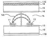
하부 및 상부 기판(10,15)이 소정 거리를 두고 대향, 배치된다. 여기서, 하부기판(10) 상부에는 기판에 수평한 전계 및 타원형의 전계를 유도하기 위하여, 액정을 구동시키는 화소 전극(11) 및 카운터 전극(12)이 이격 배치된다. 여기서, 화소 전극(11) 및 카운터 전극(12)은 불투명 금속재 예를들어, 알루미늄, 크롬 등의 물질로 형성된다. 한편, 도면에 도시되지는 않았지만, 상부 기판(15)의 대향면에는 컬러 필터와 블랙 매트릭스가 구비되어 있으며, 하부 기판(10) 상에도, 게이트 라인, 데이터 라인 및 박막 트랜지스터가 액티브 매트릭스 상태로 형성된다.The lower and
이 하부 기판(10)과 상부 기판(15) 사이에는 수개의 액정 분자를 포함하는 액정(14)이 협지된다. 본 실시예에서는 액정으로 예를들어, 유전율 이방성이 양인 액정(14)이 개재됨이 바람직하다. 여기서, 유전율 이방성이 양인 액정(14)은 이후, 전계가 형성되면, 전계 방향과 액정 분자의 장축이 평행하게 배열되는 특성을 갖는다. 또한, 상기 액정(14)에는 꼬임 특성을 갖는 카이랄 도펀트(chiral dopant)가 혼합되어질 수 있다. 이때, 전체 꼬임 주기에 대한 셀갭의 비인 디피비(d/p ratio)가 4분의 1 정도가 되도록 카이랄 도펀트가 혼합될 수 있다.The
하부 기판(10)과 상부 기판(15)의 액정(14) 대향면 각각에는 전계 인가전에, 액정(14)내 분자들을 일정 방향으로 배열시키기 위한 배향막(13,16)이 구비된다. 여기서, 배향막(13,16)은 액정 표시 소자에 전계 무인가시, 액정 분자의 장축이 기판(10,15) 표면에 대하여 수직으로 배열되도록 하는 특징을 갖는 수직 배향막이다.On the opposing surfaces of the
하부 기판(10)과 상부 기판(15)의 뒷면 각각에는 입사되는 빛을 어느 한 방향으로 편항시키기 위한 상하 편광판(17A, 17B)이 구비된다. 여기서, 상부 편광판(17A)의 편광축은 하부 편광판(17B)의 편광축과 크로스되도록 부착되고, 하부 편광판(17B)의 편광축은 화소 전극(11)과 카운터 전극(12)사이에 형성될 전기장과 45도의 각도차를 갖도록 부착됨이 바람직하다.Upper and
상기 기판(15)과 상부 편광판(17B) 사이에는 위상 보정판(18)이 개재된다. 이 위상 보정판(18)은 반경(nx, ny)에 배하여 높이(nz)가 긴 원통 형태의 액정 분자(14A)(제3(a)도 참조)들이 수직 배열시 광이 누설되는 것을 방지하기 위하여 개재되는 액정 경화 필름이다. 이 위상 보정판(18)은 원통 타입의 액정 분자(14A)들이 등방성 즉, 구형화를 유도하기 위하여 제3(b)도와 같이, 반경(nx, ny)에 비하여 높이(nz)가 짧은 디스크 타입의 액정 분자(18A)를 경화하여 형성한다.A
이러한 구성을 액정 표시 소자는, 화소 전극(11)과 카운터 전극(12)에 전압이 인가되기 이전에는 제2(a)도에 도시된 바와 같이, 액정(14)내 분자들은 상,하부 기판(10,15)의 수직 배향막들(13,16)의 영향으로 그것의 장축이 기판에 수직인 형태로 배열된다. 이에 따라, 하부 편광판(17B)을 통과한 빛은 상부 편광판(17A)을 통과하지 못하고 차단되어, 다크상태를 나타낸다. 이때, 위상 보정판(18)에 의하여 액정 분자(14A)들의 위상 즉, 굴절율 이방성이 보상되어, 전면 및 측면등 어느 면에서나 완전한 다크를 이룬다.In this configuration, before the voltage is applied to the
한편, 화소 전극(11)과 카운터 전극(12)에 소정 전압이 인가되면, 제2(b)도에 도시된 바와 같이, 화소 전극(11)과 카운터 전극(12)사이에 수평 및 타원형의 전계가 형성된다. 즉, 하부 기판(10)에 인접할수록 수평한 전계가 형성되고, 상부 기판(15)으로 향할수록 타원형의 전계가 형성된다. 이에따라, 액정 분자(14A)들은 유전율 이방성이 양이므로, 전계와 자신의 장축이 평행하게 배열된다.On the other hand, when a predetermined voltage is applied to the
여기서, 상기 화소 전극(11)과 카운터 전극(12) 사이의 중앙에 구비된 액정분자(14A)들은 전계의 영향을 덜 받게 되어, 즉, 화소 전극(11)과 카운터 전극(12) 사이의 중앙에 있는 액정 분자는 양측의 대칭적인 힘에 의하여, 초기 배열 상태를 유지한다. 이 중앙에 있는 액정 분자를 기준으로, 액정 분자(14A)는 타원 및 수평 전계에 따라 좌우 대칭적으로 배열된다. 즉, 제2(b)도에서, 중심에 수직 배열된 액정 분자의 좌측에 있는 액정 분자는 시계 방향으로 배열되고, 반면, 우측에 있는 액정 분자는 반시계 방향으로 배열된다.Here, the
따라서, 액정 분자(14A)들은 배향막에 별도의 러빙 공정을 실시하지 않고도, 액정 분자(14A)들이 좌우 대칭을 이루면서 배열되므로, 이중 도메인이 형성된다. 여기서, 화소 전극(11)과 카운터 전극(12) 사이에 형성되는 전계는 상기에서 언급한 바와 같이, 하부 편광판(17B)의 편광축과 약 45°각도차를 갖는다. 이에 따라, 하부 편광판(17B)을 통하여 직선 편광된 광은, 액정(14)을 지나면서 편광 상태가 변하여 타원 편광되고, 상부 편광판(17A)을 통과하게 되어, 화면은 화이트 상태가 된다. 이러한 액정 표시 소자는 하기의 투과율 공식에 의거하여, 최대 투과율을 얻을 수 있다.Therefore, since the
T=sin2(2χ)·sin2(π·Δnd/λ)....(식)T = sin2 (2χ) · sin2 (π · Δnd / λ) .... (expression)
T : 투과율T: transmittance
χ: 액정 분자의 광축과 편광자의 편광축이 이루는 각χ: angle formed between the optical axis of the liquid crystal molecules and the polarization axis of the polarizer
Δn : 굴절율 이방성Δn: refractive index anisotropy
d : 유효 셀갭(액정층의 두께)d: effective cell gap (thickness of the liquid crystal layer)
λ : 입사되는 광 파장λ: incident light wavelength
즉, 상기 식에서 투과율(T)은 χ가 45도 일 때, 최대 투과율을 얻을 수 있는데, 본 실시예에서는 전계 인가시, 전계의 방향(즉, 액정 분자의 광축인 장축이 배열된 방향)과 하부 편광판의 편광축이 45도를 이루므로, 최대 투과율을 얻을 수 있는 것이다.That is, in the above formula, the transmittance T can obtain the maximum transmittance when χ is 45 degrees. In this embodiment, when the electric field is applied, the direction of the electric field (that is, the direction in which the long axis, which is the optical axis of the liquid crystal molecules, is arranged) and the lower part are applied. Since the polarization axis of the polarizing plate is 45 degrees, the maximum transmittance can be obtained.
여기서, 양 기판(10,15)에 직접 접촉하는 액정 분자들은 수직 배향막(13,16)과 액정 분자 사이의 힘에 의하여 필드 형성 이전 상태를 유지한다.Here, the liquid crystal molecules in direct contact with both
이와같이, 액정 분자들이 전계를 형성하는 전계 사이에 서로 대칭되는 두방향으로 배열되어, 이중 도메인이 형성되므로, 액정 표시 소자의 좌우 시야각 특성이 개선되고, 다크시 광누설을 없앨 수 있다.As such, since the liquid crystal molecules are arranged in two directions symmetrically between electric fields forming an electric field, and dual domains are formed, left and right viewing angle characteristics of the liquid crystal display may be improved, and dark leakage may be eliminated.
제4도는 상기와 같은 구성의 액정을 시뮬레이션한 결과를 나타낸 도면으로, 액정 분자(14A)들은 타원 및 수평 전계의 형태로 구성되어, 화소 전극(11)과 카운터 전극(12)의 중앙 부분을 중심으로 액정 분자(14A)들이 좌우 대칭이 되도록 배열된다. 따라서, 좌우 시야각 특성이 개선되고, 투과도 또한 개선됨을 도면을 통하여 확인할 수 있다.4 is a diagram showing a result of simulating a liquid crystal having the above configuration, wherein the
이상에서 자세히 설명된 바와 같이, 본 발명에 의하면, 하부 기판상에 기판과 수평하고, 타원 형태의 전계를 형성하기 위하여, 화소 전극과 카운터 전극을 이격 배치하고, 하부 기판 및 상부 기판 표면에 수직 배향막을 형성한다. 이에따라, 화소 전극과 카운터 전극의 전계 인가시, 화소 전극과 카운터 전극의 중심선을 기준으로 액정 분자들이 좌우 대칭적으로 배열된다. 이와같은 액정 분자와 좌우 대칭적 배열로서, 액정 표시 소자의 좌우 시야각 특성이 크게 개선되어, 광시야각을 얻을 수 있다.As described in detail above, according to the present invention, in order to form an elliptic electric field horizontal to the substrate on the lower substrate, the pixel electrode and the counter electrode are spaced apart from each other, and the vertical alignment layer is disposed on the lower substrate and the upper substrate surface. To form. Accordingly, when the electric field is applied to the pixel electrode and the counter electrode, the liquid crystal molecules are arranged symmetrically with respect to the center line of the pixel electrode and the counter electrode. As a left-right symmetrical arrangement with such liquid crystal molecules, the left-right viewing angle characteristic of the liquid crystal display element is greatly improved, and a wide viewing angle can be obtained.
또한, 상부 기판 뒷면에 액정 분자들을 등방성화하기 위한 위상 보정판이 개재되어, 전압 인가전에 완전한 다크를 달성하게 된다. 따라서, 액정 표시 소자의 콘트라스트비가 개선되는 효과가 있다.In addition, a phase correction plate for isotropicizing liquid crystal molecules is interposed on the rear surface of the upper substrate, thereby achieving complete dark before voltage application. Therefore, there is an effect that the contrast ratio of the liquid crystal display element is improved.
기타, 본 발명은 그 요지를 일탈하지 않는 범위에서 다양하게 변경하여 실시할 수 있다.In addition, this invention can be implemented in various changes within the range which does not deviate from the summary.
Claims (7)
Translated fromKoreanPriority Applications (12)
| Application Number | Priority Date | Filing Date | Title |
|---|---|---|---|
| KR1019970022108AKR100254856B1 (en) | 1997-05-30 | 1997-05-30 | Liquid crystal display element |
| TW087103982ATW436655B (en) | 1997-05-30 | 1998-03-18 | Method of producing two domains within a liquid crystal layer, and liquid crystal display device and method of manufacturing the same |
| NL1008688ANL1008688C2 (en) | 1997-05-30 | 1998-03-24 | Method for producing two domains in a layer, and liquid crystal display device and method for manufacturing the same. |
| DE19813490ADE19813490B4 (en) | 1997-05-30 | 1998-03-26 | Method for producing two domains within a liquid crystal layer, LCD device and method for producing this device |
| JP10102065AJPH1124068A (en) | 1997-05-30 | 1998-03-30 | Method for forming dual domain inside liquid crystal layer, manufacture of liquid crystal display device using the method and liquid crystal display device |
| US09/050,292US6781657B1 (en) | 1997-05-30 | 1998-03-30 | Method of producing two domains within a liquid crystal layer and liquid crystal display device |
| CNB98107765XACN1154008C (en) | 1997-05-30 | 1998-04-29 | Method of producing two domains within liquid crystal layer, and liquid crystal display device and method of manufacturing |
| GB9809577AGB2325751B (en) | 1997-05-30 | 1998-05-05 | Method of producing two domains within a liquid crystal layer,and liquid crystal display device and method of manufacturing the same |
| FR9805804AFR2764085B1 (en) | 1997-05-30 | 1998-05-07 | PROCESS FOR PRODUCING TWO DOMAINS WITHIN A LIQUID CRYSTAL LAYER, AND LIQUID CRYSTAL DISPLAY DEVICE AND MANUFACTURING METHOD THEREOF |
| IT98UD000090AIT1299800B1 (en) | 1997-05-30 | 1998-05-29 | METHOD OF PRODUCING TWO DOMAINS INSIDE A LAYER OF LIQUID CRYSTAL, A DISPLAY DEVICE A |
| FR9811076AFR2765698B1 (en) | 1997-05-30 | 1998-09-04 | ACTIVE MATRIX TYPE LIQUID CRYSTAL DISPLAY DEVICE |
| FR9811075AFR2765697B1 (en) | 1997-05-30 | 1998-09-04 | PROCESS FOR PRODUCING TWO DOMAINS WITHIN A LIQUID CRYSTAL LAYER |
Applications Claiming Priority (1)
| Application Number | Priority Date | Filing Date | Title |
|---|---|---|---|
| KR1019970022108AKR100254856B1 (en) | 1997-05-30 | 1997-05-30 | Liquid crystal display element |
Publications (2)
| Publication Number | Publication Date |
|---|---|
| KR19980085919A KR19980085919A (en) | 1998-12-05 |
| KR100254856B1true KR100254856B1 (en) | 2000-05-01 |
Family
ID=19507980
Family Applications (1)
| Application Number | Title | Priority Date | Filing Date |
|---|---|---|---|
| KR1019970022108AExpired - LifetimeKR100254856B1 (en) | 1997-05-30 | 1997-05-30 | Liquid crystal display element |
Country Status (10)
| Country | Link |
|---|---|
| US (1) | US6781657B1 (en) |
| JP (1) | JPH1124068A (en) |
| KR (1) | KR100254856B1 (en) |
| CN (1) | CN1154008C (en) |
| DE (1) | DE19813490B4 (en) |
| FR (3) | FR2764085B1 (en) |
| GB (1) | GB2325751B (en) |
| IT (1) | IT1299800B1 (en) |
| NL (1) | NL1008688C2 (en) |
| TW (1) | TW436655B (en) |
Families Citing this family (46)
| Publication number | Priority date | Publication date | Assignee | Title |
|---|---|---|---|---|
| CN1567066B (en)* | 1997-05-30 | 2010-05-12 | 三星电子株式会社 | Liquid crystal display |
| TW434443B (en) | 1997-05-30 | 2001-05-16 | Samsung Electronics Co Ltd | Liquid crystal display |
| US6704083B1 (en) | 1997-05-30 | 2004-03-09 | Samsung Electronics, Co., Ltd. | Liquid crystal display including polarizing plate having polarizing directions neither parallel nor perpendicular to average alignment direction of molecules |
| TW509808B (en)* | 1997-06-12 | 2002-11-11 | Sharp Kk | Liquid crystal display device |
| JP2991995B2 (en) | 1997-07-14 | 1999-12-20 | 三菱電機株式会社 | Liquid crystal display |
| KR100341123B1 (en)* | 1997-12-29 | 2002-12-18 | 주식회사 현대 디스플레이 테크놀로지 | LCD having high transmittance and high aperture ratio and method for manufacturing the same |
| TW387997B (en)* | 1997-12-29 | 2000-04-21 | Hyundai Electronics Ind | Liquid crystal display and fabrication method |
| US20040109103A1 (en)* | 1998-06-30 | 2004-06-10 | Hitachi, Ltd. | Liquid crystal display device |
| US6809787B1 (en)* | 1998-12-11 | 2004-10-26 | Lg.Philips Lcd Co., Ltd. | Multi-domain liquid crystal display device |
| KR100599959B1 (en)* | 1999-12-27 | 2006-07-12 | 비오이 하이디스 테크놀로지 주식회사 | Liquid crystal display |
| KR20010064410A (en)* | 1999-12-29 | 2001-07-09 | 박종섭 | Fringe field switching mode lcd device |
| KR100599962B1 (en)* | 1999-12-29 | 2006-07-12 | 비오이 하이디스 테크놀로지 주식회사 | Fringe Field Drive LCD |
| KR20020002134A (en)* | 2000-06-29 | 2002-01-09 | 주식회사 현대 디스플레이 테크놀로지 | Fringe field switching mode lcd |
| TW594234B (en)* | 2002-12-02 | 2004-06-21 | Ind Tech Res Inst | Wide viewing angle LCD device with laterally driven electric field and its manufacturing method |
| TW200415393A (en)* | 2003-01-15 | 2004-08-16 | Toshiba Matsushita Display Tec | LCD device |
| US20040219305A1 (en)* | 2003-02-13 | 2004-11-04 | Fuji Photo Film Co., Ltd. | Retardation film and elliptically polarizing film |
| JP4087306B2 (en)* | 2003-08-28 | 2008-05-21 | シャープ株式会社 | Liquid crystal display |
| KR100577799B1 (en)* | 2004-02-16 | 2006-05-11 | 비오이 하이디스 테크놀로지 주식회사 | Arrangement of polarization axis and rubbing axis in fringe field driving mode liquid crystal display |
| KR20060086742A (en)* | 2005-01-27 | 2006-08-01 | 비오이 하이디스 테크놀로지 주식회사 | Multi Cell Gap Fringe Field Switching Mode Liquid Crystal Display |
| JP2006317656A (en)* | 2005-05-12 | 2006-11-24 | Dainippon Printing Co Ltd | Anisotropic optical element |
| KR101157290B1 (en)* | 2005-06-30 | 2012-06-15 | 엘지디스플레이 주식회사 | Liquid crystal display device capable of mode switching between a wide viewing angle and a narrow viewing angle |
| KR101197051B1 (en)* | 2005-10-05 | 2012-11-06 | 삼성디스플레이 주식회사 | Thin film transistor array panel |
| US20070195247A1 (en)* | 2006-02-23 | 2007-08-23 | James Anderson | Complementary anti-parallel substrate alignment in vertically aligned nematic liquid crystal displays |
| US20070218213A1 (en)* | 2006-03-14 | 2007-09-20 | Chih-Chien Chou | Method of manufacturing liquid crystal alignment film |
| JP4466596B2 (en)* | 2006-03-29 | 2010-05-26 | カシオ計算機株式会社 | Orientation transition method |
| US20080024704A1 (en)* | 2006-07-27 | 2008-01-31 | Chunghwa Picture Tubes, Ltd. | Liquid crystal display panel |
| KR101382481B1 (en)* | 2007-09-03 | 2014-04-09 | 삼성디스플레이 주식회사 | display device |
| US8168083B2 (en)* | 2007-09-10 | 2012-05-01 | Merck Patent Gesellschaft Mit Beschraenkter Haftung | Electro-optical light control element, electro-optical display and control medium |
| GB2455061A (en) | 2007-10-30 | 2009-06-03 | Sharp Kk | Liquid Crystal Device with three sets of electrodes for controlling tilt and azimuth angles |
| JP2009223137A (en)* | 2008-03-18 | 2009-10-01 | Seiko Epson Corp | Liquid crystal device and electronic apparatus |
| WO2009154258A1 (en) | 2008-06-18 | 2009-12-23 | シャープ株式会社 | Liquid crystal panel and liquid crystal display device |
| US8054435B2 (en)* | 2008-06-18 | 2011-11-08 | Sharp Kabushiki Kaisha | Liquid crystal panel and liquid crystal display device |
| CN102187270A (en) | 2008-10-14 | 2011-09-14 | 夏普株式会社 | Liquid crystal display device |
| BRPI1012043A2 (en) | 2009-05-27 | 2016-05-17 | Sharp Kk | liquid crystal display device |
| WO2010137363A1 (en)* | 2009-05-28 | 2010-12-02 | シャープ株式会社 | Liquid crystal display device |
| CN102282504B (en)* | 2009-05-29 | 2014-12-03 | 夏普株式会社 | Liquid crystal display device |
| JP5389923B2 (en)* | 2009-07-31 | 2014-01-15 | シャープ株式会社 | Liquid crystal panel and liquid crystal display device |
| US20120176575A1 (en) | 2009-10-30 | 2012-07-12 | Toshihiro Matsumoto | Liquid crystal display element |
| KR101198185B1 (en)* | 2010-07-27 | 2012-11-12 | 전북대학교산학협력단 | Liquid Crystal Display and method for making thereof |
| KR101368745B1 (en) | 2010-09-28 | 2014-02-28 | 디아이씨 가부시끼가이샤 | Novel liquid crystal display device and useful liquid crystal composition |
| KR101374694B1 (en) | 2010-09-28 | 2014-03-17 | 디아이씨 가부시끼가이샤 | Novel liquid crystal display device and useful liquid crystal composition |
| WO2013099717A1 (en)* | 2011-12-26 | 2013-07-04 | シャープ株式会社 | Liquid crystal display panel and liquid crystal display device |
| KR102234758B1 (en)* | 2014-07-10 | 2021-04-02 | 삼성디스플레이 주식회사 | Liquid crystal display |
| EP3507651B1 (en)* | 2016-08-30 | 2021-12-15 | BOE Technology Group Co., Ltd. | Liquid crystal display panel, liquid crystal display apparatus, and controlling method thereof |
| US10989946B2 (en)* | 2019-02-21 | 2021-04-27 | Innolux Corporation | Electronic modulating device |
| EP4307037A4 (en)* | 2021-03-12 | 2025-06-11 | Japan Display Inc. | LIQUID CRYSTAL DEVICE |
Citations (2)
| Publication number | Priority date | Publication date | Assignee | Title |
|---|---|---|---|---|
| JPH01147431A (en)* | 1987-12-02 | 1989-06-09 | Seiko Epson Corp | display device |
| KR960035089A (en)* | 1995-03-17 | 1996-10-24 | 카나이 쯔또무 | Liquid crystal display element with wide viewing angle characteristics |
Family Cites Families (18)
| Publication number | Priority date | Publication date | Assignee | Title |
|---|---|---|---|---|
| US3807831A (en)* | 1972-06-20 | 1974-04-30 | Beckman Instruments Inc | Liquid crystal display apparatus |
| GB1475378A (en)* | 1973-12-19 | 1977-06-01 | Ibm | Liquid crystal display device |
| JPS5389753A (en)* | 1977-01-18 | 1978-08-07 | Seiko Epson Corp | Liquid crystal display element |
| US4617646A (en)* | 1984-06-29 | 1986-10-14 | International Business Machines Corporation | Electric field gradient excited liquid crystal cell having bistability |
| DE3911620A1 (en)* | 1989-04-08 | 1990-10-18 | Merck Patent Gmbh | Electro=optical LCD system using ECB principle - uses conventional liquid crystal layer and non-controllable liquid crystal addition |
| DE4027981A1 (en)* | 1990-09-04 | 1992-04-30 | Merck Patent Gmbh | MATRIX liquid-crystal display |
| US5493426A (en)* | 1991-11-14 | 1996-02-20 | University Of Colorado Foundation, Inc. | Lateral electrode smectic liquid crystal devices |
| EP0588568B1 (en) | 1992-09-18 | 2002-12-18 | Hitachi, Ltd. | A liquid crystal display device |
| JPH06301036A (en)* | 1993-04-12 | 1994-10-28 | Sanyo Electric Co Ltd | Liquid crystal display device |
| US5477358A (en)* | 1993-06-21 | 1995-12-19 | Case Western Reserve University | Chiral nematic liquid crystal display with homeotropic alignment and negative dielectric anisotropy |
| JP2975844B2 (en)* | 1993-06-24 | 1999-11-10 | 三洋電機株式会社 | Liquid crystal display |
| JPH086025A (en)* | 1994-04-20 | 1996-01-12 | Sharp Corp | Liquid crystal electro-optical device, projection type display system using the same, and method of driving liquid crystal electro-optical device |
| JPH0961825A (en)* | 1995-08-28 | 1997-03-07 | Sharp Corp | Liquid crystal display |
| JPH09105941A (en)* | 1995-10-13 | 1997-04-22 | Stanley Electric Co Ltd | Liquid crystal display |
| JP3282986B2 (en)* | 1996-02-28 | 2002-05-20 | 富士通株式会社 | Liquid crystal display |
| JP3194127B2 (en) | 1996-04-16 | 2001-07-30 | 大林精工株式会社 | Liquid crystal display |
| US6642981B1 (en)* | 1996-09-30 | 2003-11-04 | Fujitsu Display Technologies Corporation | Liquid crystal display device operating in a vertically aligned mode including at least one retardation film |
| CN1567066B (en)* | 1997-05-30 | 2010-05-12 | 三星电子株式会社 | Liquid crystal display |
- 1997
- 1997-05-30KRKR1019970022108Apatent/KR100254856B1/ennot_activeExpired - Lifetime
- 1998
- 1998-03-18TWTW087103982Apatent/TW436655B/ennot_activeIP Right Cessation
- 1998-03-24NLNL1008688Apatent/NL1008688C2/ennot_activeIP Right Cessation
- 1998-03-26DEDE19813490Apatent/DE19813490B4/ennot_activeExpired - Lifetime
- 1998-03-30USUS09/050,292patent/US6781657B1/ennot_activeExpired - Lifetime
- 1998-03-30JPJP10102065Apatent/JPH1124068A/enactivePending
- 1998-04-29CNCNB98107765XApatent/CN1154008C/ennot_activeExpired - Lifetime
- 1998-05-05GBGB9809577Apatent/GB2325751B/ennot_activeExpired - Lifetime
- 1998-05-07FRFR9805804Apatent/FR2764085B1/ennot_activeExpired - Lifetime
- 1998-05-29ITIT98UD000090Apatent/IT1299800B1/enactiveIP Right Grant
- 1998-09-04FRFR9811075Apatent/FR2765697B1/ennot_activeExpired - Lifetime
- 1998-09-04FRFR9811076Apatent/FR2765698B1/ennot_activeExpired - Lifetime
Patent Citations (2)
| Publication number | Priority date | Publication date | Assignee | Title |
|---|---|---|---|---|
| JPH01147431A (en)* | 1987-12-02 | 1989-06-09 | Seiko Epson Corp | display device |
| KR960035089A (en)* | 1995-03-17 | 1996-10-24 | 카나이 쯔또무 | Liquid crystal display element with wide viewing angle characteristics |
Also Published As
| Publication number | Publication date |
|---|---|
| ITUD980090A1 (en) | 1999-11-29 |
| FR2765697B1 (en) | 2004-11-19 |
| US6781657B1 (en) | 2004-08-24 |
| DE19813490A1 (en) | 1998-12-03 |
| GB9809577D0 (en) | 1998-07-01 |
| JPH1124068A (en) | 1999-01-29 |
| CN1154008C (en) | 2004-06-16 |
| TW436655B (en) | 2001-05-28 |
| NL1008688C2 (en) | 2004-02-17 |
| GB2325751A (en) | 1998-12-02 |
| FR2765698A1 (en) | 1999-01-08 |
| IT1299800B1 (en) | 2000-04-04 |
| KR19980085919A (en) | 1998-12-05 |
| FR2764085B1 (en) | 2004-12-17 |
| DE19813490B4 (en) | 2004-12-09 |
| FR2765697A1 (en) | 1999-01-08 |
| NL1008688A1 (en) | 1998-12-01 |
| GB2325751B (en) | 2001-10-17 |
| CN1201063A (en) | 1998-12-09 |
| FR2765698B1 (en) | 2004-12-17 |
| FR2764085A1 (en) | 1998-12-04 |
Similar Documents
| Publication | Publication Date | Title |
|---|---|---|
| KR100254856B1 (en) | Liquid crystal display element | |
| KR100248210B1 (en) | Liquid crystal display element | |
| KR100671509B1 (en) | Fringe Field Drive LCD | |
| US6266118B1 (en) | Liquid crystal display of high aperture ratio and high transmittance having multi-domain having transparent conductive pixel and counter electrodes on the same substrate | |
| JP3826214B2 (en) | High aperture ratio and high transmittance liquid crystal display device | |
| US6141075A (en) | Liquid crystal display device operating in a vertically aligned mode | |
| US6088078A (en) | Liquid crystal display with horizontal electric field | |
| JP3479696B2 (en) | Liquid crystal display | |
| US7176999B2 (en) | Liquid crystal display device | |
| US6215542B1 (en) | Liquid crystal display with improved viewing angle and transmittance | |
| US6512503B1 (en) | Liquid crystal display | |
| US6469764B1 (en) | Liquid crystal display and method for manufacturing the same | |
| KR19990048089A (en) | Liquid crystal display element | |
| KR100327927B1 (en) | Liquid crystal display device | |
| KR100303351B1 (en) | Vertical alignment mode liquid crystal display | |
| JP3776844B2 (en) | Liquid crystal display | |
| KR100241484B1 (en) | Liquid crystal display | |
| KR20030061584A (en) | 2-domain ffs-va mode liquid crystal display device | |
| KR100368988B1 (en) | High Opening and High Transmittance Liquid Crystal Display | |
| KR100293807B1 (en) | LCD | |
| KR100272267B1 (en) | Lcd device | |
| KR100488935B1 (en) | LCD display device of HSN mode | |
| KR100648217B1 (en) | Vertical alignment mode LCD | |
| KR100658059B1 (en) | Twisted nematic liquid crystal display with improved viewing angle | |
| KR100674231B1 (en) | Fringe Field Drive Mode Liquid Crystal Display |
Legal Events
| Date | Code | Title | Description |
|---|---|---|---|
| A201 | Request for examination | ||
| PA0109 | Patent application | Patent event code:PA01091R01D Comment text:Patent Application Patent event date:19970530 | |
| PA0201 | Request for examination | Patent event code:PA02012R01D Patent event date:19970530 Comment text:Request for Examination of Application | |
| PG1501 | Laying open of application | ||
| E902 | Notification of reason for refusal | ||
| PE0902 | Notice of grounds for rejection | Comment text:Notification of reason for refusal Patent event date:19990712 Patent event code:PE09021S01D | |
| E701 | Decision to grant or registration of patent right | ||
| PE0701 | Decision of registration | Patent event code:PE07011S01D Comment text:Decision to Grant Registration Patent event date:19991109 | |
| GRNT | Written decision to grant | ||
| PR0701 | Registration of establishment | Comment text:Registration of Establishment Patent event date:20000208 Patent event code:PR07011E01D | |
| PR1002 | Payment of registration fee | Payment date:20000209 End annual number:3 Start annual number:1 | |
| PG1601 | Publication of registration | ||
| PR1001 | Payment of annual fee | Payment date:20021227 Start annual number:4 End annual number:4 | |
| PR1001 | Payment of annual fee | Payment date:20031217 Start annual number:5 End annual number:5 | |
| PR1001 | Payment of annual fee | Payment date:20041216 Start annual number:6 End annual number:6 | |
| PR1001 | Payment of annual fee | Payment date:20060104 Start annual number:7 End annual number:7 | |
| PR1001 | Payment of annual fee | Payment date:20070126 Start annual number:8 End annual number:8 | |
| PR1001 | Payment of annual fee | Payment date:20080110 Start annual number:9 End annual number:9 | |
| PR1001 | Payment of annual fee | Payment date:20090119 Start annual number:10 End annual number:10 | |
| PR1001 | Payment of annual fee | Payment date:20100127 Start annual number:11 End annual number:11 | |
| PR1001 | Payment of annual fee | Payment date:20101216 Start annual number:12 End annual number:12 | |
| PR1001 | Payment of annual fee | Payment date:20111229 Start annual number:13 End annual number:13 | |
| FPAY | Annual fee payment | Payment date:20130107 Year of fee payment:14 | |
| PR1001 | Payment of annual fee | Payment date:20130107 Start annual number:14 End annual number:14 | |
| FPAY | Annual fee payment | Payment date:20140116 Year of fee payment:15 | |
| PR1001 | Payment of annual fee | Payment date:20140116 Start annual number:15 End annual number:15 | |
| FPAY | Annual fee payment | Payment date:20150116 Year of fee payment:16 | |
| PR1001 | Payment of annual fee | Payment date:20150116 Start annual number:16 End annual number:16 | |
| PR1001 | Payment of annual fee | Payment date:20160115 Start annual number:17 End annual number:17 | |
| FPAY | Annual fee payment | Payment date:20170119 Year of fee payment:18 | |
| PR1001 | Payment of annual fee | Payment date:20170119 Start annual number:18 End annual number:18 | |
| PC1801 | Expiration of term |