KR100252443B1 - Image transmission apparatus and operation inspection method of the apparatus - Google Patents
Image transmission apparatus and operation inspection method of the apparatusDownload PDFInfo
- Publication number
- KR100252443B1 KR100252443B1KR1019970000596AKR19970000596AKR100252443B1KR 100252443 B1KR100252443 B1KR 100252443B1KR 1019970000596 AKR1019970000596 AKR 1019970000596AKR 19970000596 AKR19970000596 AKR 19970000596AKR 100252443 B1KR100252443 B1KR 100252443B1
- Authority
- KR
- South Korea
- Prior art keywords
- ink
- energy
- reservoir
- transfer means
- transfer
- Prior art date
- Legal status (The legal status is an assumption and is not a legal conclusion. Google has not performed a legal analysis and makes no representation as to the accuracy of the status listed.)
- Expired - Fee Related
Links
Images


Classifications
- B—PERFORMING OPERATIONS; TRANSPORTING
- B41—PRINTING; LINING MACHINES; TYPEWRITERS; STAMPS
- B41J—TYPEWRITERS; SELECTIVE PRINTING MECHANISMS, i.e. MECHANISMS PRINTING OTHERWISE THAN FROM A FORME; CORRECTION OF TYPOGRAPHICAL ERRORS
- B41J2/00—Typewriters or selective printing mechanisms characterised by the printing or marking process for which they are designed
- B41J2/005—Typewriters or selective printing mechanisms characterised by the printing or marking process for which they are designed characterised by bringing liquid or particles selectively into contact with a printing material
- B41J2/01—Ink jet
- B41J2/17—Ink jet characterised by ink handling
- B41J2/195—Ink jet characterised by ink handling for monitoring ink quality
- B—PERFORMING OPERATIONS; TRANSPORTING
- B41—PRINTING; LINING MACHINES; TYPEWRITERS; STAMPS
- B41J—TYPEWRITERS; SELECTIVE PRINTING MECHANISMS, i.e. MECHANISMS PRINTING OTHERWISE THAN FROM A FORME; CORRECTION OF TYPOGRAPHICAL ERRORS
- B41J2/00—Typewriters or selective printing mechanisms characterised by the printing or marking process for which they are designed
- B41J2/005—Typewriters or selective printing mechanisms characterised by the printing or marking process for which they are designed characterised by bringing liquid or particles selectively into contact with a printing material
- B41J2/01—Ink jet
- B41J2/015—Ink jet characterised by the jet generation process
- B41J2/04—Ink jet characterised by the jet generation process generating single droplets or particles on demand
- B41J2/045—Ink jet characterised by the jet generation process generating single droplets or particles on demand by pressure, e.g. electromechanical transducers
- B41J2/04501—Control methods or devices therefor, e.g. driver circuits, control circuits
- B41J2/0451—Control methods or devices therefor, e.g. driver circuits, control circuits for detecting failure, e.g. clogging, malfunctioning actuator
- B—PERFORMING OPERATIONS; TRANSPORTING
- B41—PRINTING; LINING MACHINES; TYPEWRITERS; STAMPS
- B41J—TYPEWRITERS; SELECTIVE PRINTING MECHANISMS, i.e. MECHANISMS PRINTING OTHERWISE THAN FROM A FORME; CORRECTION OF TYPOGRAPHICAL ERRORS
- B41J2/00—Typewriters or selective printing mechanisms characterised by the printing or marking process for which they are designed
- B41J2/005—Typewriters or selective printing mechanisms characterised by the printing or marking process for which they are designed characterised by bringing liquid or particles selectively into contact with a printing material
- B41J2/01—Ink jet
- B41J2/015—Ink jet characterised by the jet generation process
- B41J2/04—Ink jet characterised by the jet generation process generating single droplets or particles on demand
- B41J2/045—Ink jet characterised by the jet generation process generating single droplets or particles on demand by pressure, e.g. electromechanical transducers
- B41J2/04501—Control methods or devices therefor, e.g. driver circuits, control circuits
- B41J2/04541—Specific driving circuit
- B—PERFORMING OPERATIONS; TRANSPORTING
- B41—PRINTING; LINING MACHINES; TYPEWRITERS; STAMPS
- B41J—TYPEWRITERS; SELECTIVE PRINTING MECHANISMS, i.e. MECHANISMS PRINTING OTHERWISE THAN FROM A FORME; CORRECTION OF TYPOGRAPHICAL ERRORS
- B41J2/00—Typewriters or selective printing mechanisms characterised by the printing or marking process for which they are designed
- B41J2/005—Typewriters or selective printing mechanisms characterised by the printing or marking process for which they are designed characterised by bringing liquid or particles selectively into contact with a printing material
- B41J2/01—Ink jet
- B41J2/015—Ink jet characterised by the jet generation process
- B41J2/04—Ink jet characterised by the jet generation process generating single droplets or particles on demand
- B41J2/045—Ink jet characterised by the jet generation process generating single droplets or particles on demand by pressure, e.g. electromechanical transducers
- B41J2/04501—Control methods or devices therefor, e.g. driver circuits, control circuits
- B41J2/04546—Multiplexing
- B—PERFORMING OPERATIONS; TRANSPORTING
- B41—PRINTING; LINING MACHINES; TYPEWRITERS; STAMPS
- B41J—TYPEWRITERS; SELECTIVE PRINTING MECHANISMS, i.e. MECHANISMS PRINTING OTHERWISE THAN FROM A FORME; CORRECTION OF TYPOGRAPHICAL ERRORS
- B41J2/00—Typewriters or selective printing mechanisms characterised by the printing or marking process for which they are designed
- B41J2/005—Typewriters or selective printing mechanisms characterised by the printing or marking process for which they are designed characterised by bringing liquid or particles selectively into contact with a printing material
- B41J2/01—Ink jet
- B41J2/015—Ink jet characterised by the jet generation process
- B41J2/04—Ink jet characterised by the jet generation process generating single droplets or particles on demand
- B41J2/045—Ink jet characterised by the jet generation process generating single droplets or particles on demand by pressure, e.g. electromechanical transducers
- B41J2/04501—Control methods or devices therefor, e.g. driver circuits, control circuits
- B41J2/0458—Control methods or devices therefor, e.g. driver circuits, control circuits controlling heads based on heating elements forming bubbles
- B—PERFORMING OPERATIONS; TRANSPORTING
- B41—PRINTING; LINING MACHINES; TYPEWRITERS; STAMPS
- B41J—TYPEWRITERS; SELECTIVE PRINTING MECHANISMS, i.e. MECHANISMS PRINTING OTHERWISE THAN FROM A FORME; CORRECTION OF TYPOGRAPHICAL ERRORS
- B41J2/00—Typewriters or selective printing mechanisms characterised by the printing or marking process for which they are designed
- B41J2/005—Typewriters or selective printing mechanisms characterised by the printing or marking process for which they are designed characterised by bringing liquid or particles selectively into contact with a printing material
- B41J2/01—Ink jet
- B41J2/135—Nozzles
- B41J2/165—Prevention or detection of nozzle clogging, e.g. cleaning, capping or moistening for nozzles
- B—PERFORMING OPERATIONS; TRANSPORTING
- B41—PRINTING; LINING MACHINES; TYPEWRITERS; STAMPS
- B41J—TYPEWRITERS; SELECTIVE PRINTING MECHANISMS, i.e. MECHANISMS PRINTING OTHERWISE THAN FROM A FORME; CORRECTION OF TYPOGRAPHICAL ERRORS
- B41J2/00—Typewriters or selective printing mechanisms characterised by the printing or marking process for which they are designed
- B41J2/005—Typewriters or selective printing mechanisms characterised by the printing or marking process for which they are designed characterised by bringing liquid or particles selectively into contact with a printing material
- B41J2/01—Ink jet
- B41J2/17—Ink jet characterised by ink handling
- B41J2/175—Ink supply systems ; Circuit parts therefor
- B41J2/17566—Ink level or ink residue control
Landscapes
- Engineering & Computer Science (AREA)
- Quality & Reliability (AREA)
- Ink Jet (AREA)
- Particle Formation And Scattering Control In Inkjet Printers (AREA)
Abstract
Translated fromKoreanDescription
Translated fromKorean제1도는 본 발명의 제1 및 제2실시예에 따른 화상 전송 장치의 일실시예의 블럭도.1 is a block diagram of one embodiment of an image transmitting apparatus according to the first and second embodiments of the present invention.
제2도는 제1도의 장치에서 사용되는 잉크 액적 분사 방식의 인쇄 헤드의 개략적인 투시도.FIG. 2 is a schematic perspective view of a print head of ink droplet ejection type used in the apparatus of FIG.
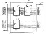
제3도는 제2도의 인쇄 헤드에 배치되는 잉크 분사 헤드의 전기 부품의 다이어그램.3 is a diagram of the electrical components of the ink jet head disposed in the print head of FIG.
제4도는 잉크 분사 수단의 제어 수단 중 일부분에 대한 다이어그램.4 is a diagram of a part of the control means of the ink ejecting means.
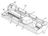
제5도는 본 발명에 따른 화상 전송 장치의 일부분에 대한 투시도.5 is a perspective view of a portion of an image transmission device according to the present invention.
제6도는 본 발명의 제2실시예에 따른 잉크 카트릿지의 단순화된 개략적인 종단면도.6 is a simplified schematic longitudinal sectional view of the ink cartridge according to the second embodiment of the present invention.
제7도는 제1도의 장치에 포함되어 있는 본 발명에 따른 변환 회로의 일실시예에 대한 블럭도.7 is a block diagram of one embodiment of a conversion circuit according to the present invention included in the apparatus of FIG.
제8도는 제1도의 장치에 포함된 잉크 분사 수단에 인가되는 제어 신호의 타이밍도.8 is a timing diagram of a control signal applied to the ink ejecting means included in the apparatus of FIG.
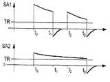
제9도는 잉크 저장소 또는 잉크 분사 수단의 동작을 검사하는 단계 중에 측정되어진 신호의 타이밍도.9 is a timing diagram of a signal measured during the step of inspecting the operation of the ink reservoir or ink ejection means.
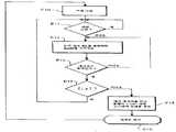
제10도는 본 발명의 제1실시예에 따른 잉크 검출 알고리즘의 제1실시예도.10 is a first embodiment of an ink detection algorithm according to the first embodiment of the present invention.
제11도는 본 발명의 제1실시예에 따른 잉크 검출 알고리즘의 제2실시예도.11 is a second embodiment of an ink detection algorithm according to the first embodiment of the present invention.
제12도는 본 발명의 제1실시예에 따른 잉크 검출 알고리즘의 제3실시예도.12 is a third embodiment of an ink detection algorithm according to the first embodiment of the present invention.
제13도는 제2도의 인쇄 헤드에 배치되며 본 발명의 제2실시예에서 사용되는 잉크 분사 수단의 일부에 대한 단순화된 개략적인 종단면도.FIG. 13 is a simplified schematic longitudinal sectional view of a portion of the ink ejecting means disposed in the print head of FIG. 2 and used in the second embodiment of the present invention.
제14도는 본 발명의 제2실시예에 따른 잉크 분사 수단 및 잉크 카트릿지의 전기 부품에 대한 단순화된 전기 다이어그램.14 is a simplified electrical diagram of the electrical components of the ink jetting means and the ink cartridge according to the second embodiment of the present invention.
제15도는 본 발명의 제2실시예에 따른 동작-검사 알고리즘의 일실시예도.15 is an embodiment of an operation-checking algorithm according to a second embodiment of the present invention.
* 도면의 주요부분에 대한 부호의 설명* Explanation of symbols for main parts of the drawings
10 : 화상 전송 수단 100 : 주 데이타 처리 회로10: image transmission means 100: main data processing circuit
110 : 잉크 분사 제어 회로 111 : 잉크 카트릿지110: ink ejection control circuit 111: ink cartridge
112 : 잉크 저장소 113 : 인쇄 헤드112: ink reservoir 113: print head
118 : 퍼지 펌프118: Purge Pump
본 발명은 일반적으로 적어도 잉크 전사 수단에 관련된 잉크 저장소를 갖는 화상 전송 장치에 관한 것이다.The present invention relates generally to an image transfer apparatus having at least an ink reservoir associated with an ink transfer means.
잉크 저장소 및 잉크 전사 수단은 단일 조립체이거나, 또는 독립된 2개의 구조체일 수 있다. 그러나, 여하튼, 잉크 저장소 및 잉크 전사 수단은 사용자에게는 부품(unit)으로서 인식되므로, 그 작용에 대해 검사할 필요가 있다. 본 발명은 특히 화상 전송 장치의 잉크 저장소 및 잉크 전사 수단을 구비하는 부품의 동작을 검사하기 위한 방법 및 장치에 관한 것이다.The ink reservoir and ink transfer means may be a single assembly or two separate structures. In any case, however, the ink reservoir and the ink transfer means are recognized by the user as a unit, and therefore need to be inspected for their operation. The present invention relates in particular to a method and apparatus for inspecting the operation of a component comprising an ink reservoir and ink transfer means of an image transfer apparatus.
한편, 잉크-젯 프린터 등의 잉크-젯 기술을 이용하는 화상 전송 장치에 있어서, 잉크의 부재를 검출하기 위한 각종 장치 및 방법들이 고안되어 있다.On the other hand, in an image transmission apparatus using ink-jet technology such as an ink-jet printer, various apparatuses and methods for detecting the absence of ink have been devised.
공지된 제1검출 방식에서는 2개 전극 간에서의 잉크 저항을 측정함으로써 잉크의 전기 특성을 이용하는 것이다.In the first known detection method, the electrical properties of the ink are used by measuring the ink resistance between two electrodes.
문헌 EP-A-0-370 765호에서는 잉크 분사 헤드를 잉크 저장소에 연결시키는 채널에 위치된 2개 전극과 이들 2개 전극 간에서의 전기 저항을 검출하는 수단을 포함하는 검출 장치에 대해 기재되어 있다. 제1전극은 잉크 분사 헤드에 근접 위치되는 반면에, 제2전극은 잉크 분사 헤드에서 떨어져 위치되어, 이들 두 전극 간에는 전위차가 인가된다. 잉크의 저항을 측정하여 측정된 저항값으로부터 잉크의 존재 유무를 검출한다.Document EP-A-0-370 765 describes a detection device comprising two electrodes located in a channel connecting an ink ejection head to an ink reservoir and means for detecting electrical resistance between these two electrodes. have. The first electrode is located proximate to the ink ejection head, while the second electrode is located away from the ink ejection head, so that a potential difference is applied between these two electrodes. The resistance of the ink is measured to detect the presence or absence of ink from the measured resistance value.
이들 두 전극은 반드시 소정 거리만큼 떨어져 위치되어야 하는데, 이로 인해 제조가 복잡해져 제조 비용이 상승된다.These two electrodes must be located a certain distance apart, which leads to complicated manufacturing and increases manufacturing costs.
또한, 카트릿지에 위치되어 있는 전극들은 시트(sheet)를 따라 카트릿지를 이동시키는 캐리지의 좌우 이동을 받게 된다. 이러한 좌우 이동에 의해 잉크 레벨의 검출이 방해를 받게 되므로 연속 측정, 즉 서류의 인쇄 동안의 측정이 곤란해진다.In addition, the electrodes located in the cartridge are subjected to the left and right movement of the carriage for moving the cartridge along the sheet. Since the detection of the ink level is hindered by such lateral movement, continuous measurement, that is, measurement during printing of the document becomes difficult.
또한, 상호 연결 시스템에 잉크를 검출하는데 필요한 다른 연결부를 제공할 필요가 있다.There is also a need to provide the interconnect system with other connections necessary to detect ink.
칼라 프린터 등과 같이 여러개의 잉크 저장소를 갖는 프린터의 경우에는, 각각의 저장소에 전극을 제공해야만 하므로 검출 장치가 매우 고가로 되었다.In the case of a printer having a plurality of ink reservoirs, such as a color printer, the detection apparatus becomes very expensive because an electrode must be provided in each reservoir.
또한, 이들 장치는 잉크 내의 공기 버블의 존재를 검출할 수 없으므로 공기 버블에 의해 서류를 완전히 재현시킬 수 없었다. 공기 버블의 문제는 잉크 저장소 및 분사 헤드가 독립되어 있는 잉크 카트릿지를 사용한 화상 전송 장치에서 특히 심각한 것으로 관찰되었다. 더우기, 이들 장치 내의 잉크 저장소를 교환할 경우, 공기 버블을 배기시키기 위해 잉크 저장소에 연결되어 있는 분사 헤드 및 채널을 완전히 퍼지(purge)시킨다. 따라서, 단지 이들 공기 버블을 배기시키려는 목적으로만 대량의 잉크가 소모되어진다.In addition, these devices could not detect the presence of air bubbles in the ink and thus could not completely reproduce the document by the air bubbles. The problem of air bubbles has been observed to be particularly serious in an image transfer apparatus using an ink cartridge having independent ink reservoirs and ejection heads. Moreover, when the ink reservoirs in these devices are exchanged, the ejection heads and channels connected to the ink reservoirs are purged completely to exhaust the air bubbles. Therefore, a large amount of ink is consumed only for the purpose of evacuating these air bubbles.
공지된 제2검출 방식은 인쇄해야 할 서류에 대한 모티프(motif)를 재현하여 이 모티프를 광 센서에 의해 검출하는 것으로 이루어져 있다. 이것에 대해서는 JP-A-6 126 951에서 기재되어 있다.The second known detection scheme consists in reproducing a motif for a document to be printed and detecting this motif by an optical sensor. This is described in JP-A-6 126 951.
제2검출 방식은 잉크 카트릿지의 복잡성을 증가시키지는 않지만, 광 센서를 이용함으로써 인쇄 장치의 가격이 상승한다. 또한, 서류에 인쇄 영역, 예를 들어, 인쇄된 각 페이지의 말미에 블랙 스퀘어(black square)를 부가할 필요가 있어서, 재현된 서류의 품질이 손상을 받게 된다. 그러므로, 이러한 방식의 잉크 검출은 특정 용도에만 사용될 수 있다.The second detection method does not increase the complexity of the ink cartridge, but the price of the printing apparatus is increased by using the optical sensor. In addition, it is necessary to add a black square at the end of the printed area, for example, each printed page, to the document, which impairs the quality of the reproduced document. Therefore, ink detection in this manner can only be used for specific applications.
광 검출은 또한 사용되는 인쇄 매체와 잉크에도 감응한다. 백색 종이에 대해서는 흑색의 잉크가 검출하기에 가장 용이하다. 그러나, 오늘날에는 각종의 인쇄 매체가 존재하는데, 예를 들어, 칼라 종이, 재생 종이 또는 투명 종이 등이 있다. 이러한 매체에서는 이와 같은 방법을 이용하는 것이 제한되어진다.Light detection is also sensitive to the printing media and inks used. For white paper, black ink is the easiest to detect. However, various print media exist today, such as color paper, recycled paper, or transparent paper. Use of such methods is limited in such media.
더우기, 페이지는 인쇄되지만 검출에 사용되는 블랙 스퀘어가 인쇄되지 않을 때 잉크에 공기 버블이 존재할 경우, 공기 버블은 검출되지 않을 것이다.Moreover, if there are air bubbles in the ink when the page is printed but the black square used for detection is not printed, the air bubbles will not be detected.
최종적으로, 이러한 방식의 검출기는 칼라 인쇄에 사용하기에는 곤란한데, 이것은 사용되는 각각의 칼라를 인식할 수 있는 검출기를 필요로 하기 때문이다. 인쇄 매체 상에는 각각의 칼라 모티프가 인쇄되어야 한다.Finally, this type of detector is difficult to use for color printing because it requires a detector capable of recognizing each color used. Each color motif must be printed on the print medium.
한편, 잉크-젯 프린터와 같이 잉크-젯 기술을 이용하는 화상 전송 장치에 있어서는, 인쇄 헤드가 다수의 잉크 전사 수단을 분사 채널 형태로 거의 동일하고 평행으로 갖고 있어, 여러개의 잉크 액적들이 동시에 분사될 수 있으므로 화상 전송 장치의 인쇄 속도가 향상된다.On the other hand, in an image transmission apparatus using ink-jet technology such as an ink-jet printer, the print head has a plurality of ink transfer means almost identically and in parallel in the form of ejection channels, so that multiple ink droplets can be ejected at the same time. Therefore, the printing speed of the image transfer device is improved.
서류에서 양호한 재현 품질을 얻기 위해서는, 해상도, 즉 단위 면적당 인쇄되는 도트수가 높아야 한다. 따라서, 단위 면적당 잉크 분사 채널 수가 증가하게 되어 잉크 분사 채널의 직경은 축소되어진다.In order to obtain good reproduction quality in the document, the resolution, i.e., the number of dots printed per unit area, must be high. Therefore, the number of ink ejection channels per unit area increases, so that the diameter of the ink ejection channels is reduced.
이러한 잉크 분사 채널의 크기와 조밀 상태로 인해 잉크 분사 수단을 사용하기가 복잡해서 오기능이 일어날 수 있다. 이러한 오기능은 특히 하나 이상의 잉크 분사 채널에 잉크 분사 명령이 전달되었음에도 불구하고 잉크 분사 채널이 어떠한 잉크도 분사시키지 않는다는 사실로부터 인쇄를 불만족스럽게 변형시킨다.Due to the size and dense state of the ink ejection channel, it is complicated to use the ink ejection means and malfunction may occur. This malfunction unsatisfactorily transforms the print, especially from the fact that the ink ejection channel does not eject any ink even though an ink ejection command has been delivered to one or more ink ejection channels.
이들 오기능이 원인으로서는, 예를 들어, 분사 채널을 차단시키는 불순물이나, 또는 채널 내에서 건조되어진 얼마간의 잉크나 채널 내의 잉크 부재 등이 있다.These malfunctions include, for example, impurities that block the injection channel, some ink dried in the channel, an ink member in the channel, and the like.
이들 오기능 중 일부를 피하기 위해 잉크 분사 수단에 대한 클리닝(cleaning) 및 퍼지(purging) 단계를 제공할 수 있다. 그러나, 이들 단계에서는 상당량의 잉크가 소모가 수반되어진다.In order to avoid some of these malfunctions, cleaning and purging steps for the ink ejection means may be provided. However, these steps involve a considerable amount of ink consumption.
따라서, 본 발명의 목적은 잉크 저장소 및 잉크 전사 수단을 구비하는 부품의 동작을 검사하여 상기 부품의 어떠한 종류의 오기능이라도 검출하는 한편, 이용하기에 단순하며 경제적인 정치 및 방법을 제공함으로써 종래 기술의 단점을 극복하는데 있다.It is therefore an object of the present invention to examine the operation of a component having an ink reservoir and ink transfer means to detect any kind of malfunction of the component, while providing a stationary and method that is simple and economical to use. To overcome the disadvantages.
본 발명자들은 연구 중에서, 분사 채널 내에 내포된 잉크로 전기 에너지를 전달한 후, 나타난 결과를 분석함으로써 당해 잉크 저장소 및 채널을 구비하는 부품의 동작에 관한 정보를 도출해낼 수 있는 것으로 판단하였다.The inventors determined that, during the study, the electrical energy was transferred to the ink contained in the ejection channel, and then the information about the operation of the component having the ink reservoir and the channel could be derived by analyzing the result.
이에 관련하여, 본 발명은 화상 전송 장치에서, 적어도 잉크 전사 수단에 연결된 잉크 저장소를 구비한 부품의 동작을 검사하기 위한 장치에 있어서, 상기 부품의 동작을 검사할 목적으로,In this regard, the present invention relates to an apparatus for inspecting the operation of a component having at least an ink reservoir connected to an ink transfer means in an image transfer apparatus, for the purpose of inspecting the operation of the component,
잉크 전사 수단에 내포되어 있는 잉크로 에너지를 전달하기 위한 수단과,Means for transferring energy to the ink contained in the ink transfer means,
잉크에 전달된 에너지를 분석하기 위한 수단을 포함하는 장치를 제공하는 것을 특징으로 한다.It provides a device comprising means for analyzing the energy delivered to the ink.
본 발명은 화상 전송 장치에서 적어도 잉크 전사 수단에 연결된 잉크 저장소를 구비하는 부품의 동작을 검사하기 위한 장치에 있어서,The present invention relates to an apparatus for inspecting the operation of a component having an ink reservoir connected at least to an ink transfer means in an image transfer apparatus,
전기 신호를 발생시키기 위한 수단과,Means for generating an electrical signal,
잉크 전사 수단에 내포된 잉크로 전기 신호의 에너지를 전달하기 위한 수단과,Means for transferring energy of an electrical signal to ink contained in the ink transfer means;
잉크에 전달된 에너지를 검출하기 위한 수단과,Means for detecting energy delivered to the ink,
검출된 에너지에 따라 상기 부품의 동작을 나타내는 신호를 생성시키기 위한 수단을 포함하는 장치를 제공하는 것을 특징으로 한다.And means for generating a signal indicative of the operation of the component in accordance with the detected energy.
이에 관련하여, 본 발명은 화상 전송 장치에서 적어도 잉크 전사 수단에 연결된 잉크 저장소를 구비한 부품의 동작을 검사하기 위한 방법에 있어서, 상기 부품의 동작을 검사할 목적으로,In this regard, the present invention relates to a method for inspecting the operation of a part having an ink reservoir connected to at least an ink transfer means in an image transfer apparatus, for the purpose of inspecting the operation of the part,
잉크 전사 수단에 내포되어 있는 잉크로 에너지를 전달하는 단계와,Transferring energy to ink contained in the ink transfer means;
잉크에 전달된 에너지를 분석하는 단계를 포함하는 방법을 제공하는 것을 특징으로 한다.It provides a method comprising the step of analyzing the energy delivered to the ink.
본 발명은 화상 전송 장치에서, 적어도 잉크 전사 수단에 연결된 잉크 저장소를 포함하는 부품의 동작을 검사하기 위한 방법에 있어서,The present invention relates to a method for inspecting an operation of a component including at least an ink reservoir connected to an ink transfer means in an image transmission apparatus,
전기 신호를 발생하여, 잉크 전사 수단에 내포된 잉크로 전기 신호의 에너지를 전달하는 단계와,Generating an electrical signal to transfer energy of the electrical signal to the ink contained in the ink transfer means;
잉크에 전달된 에너지를 검출하는 단계와,Detecting the energy delivered to the ink;
검출된 에너지에 따라 잉크 전사 수단의 동작을 나타내는 신호를 생성시키는 위한 단계를 포함하는 방법을 제공하는 것을 특징으로 한다.And a step for generating a signal indicative of the operation of the ink transfer means in accordance with the detected energy.
본 발명에 따른 장치 및 방법은 상술된 기술적 문제를 해결하는 이점뿐 아니라, 화상 전송 장치에 대한 변형을 거의 필요로 하지 않는 이점을 가지므로, 경제적이며, 예를 들어, 잉크-젯 프린터 또는 레이저 프린터 등의 대다수의 기존 화상 전송 장치에 적합될 수 있다.The apparatus and method according to the invention are not only advantageous in solving the above-mentioned technical problems, but also advantageous in that they require little modification to the image transmission apparatus, and therefore are economical, for example ink-jet printers or laser printers. It can be suitable for the majority of existing image transmission apparatuses.
본 발명에 따른 검사 장치는 잉크가 단지 전도성만 있다면 잉크의 종류(칼라, 조성 등)에는 관계없이 동작한다. 여기서 말하는 잉크란 인쇄 매체의 광 인자(optical factor)를 변형시키도록 설계되어진 액상, 고상, 가스상 또는 분말 상태의 임의 제품을 의미하는 것이다.The inspection apparatus according to the invention operates irrespective of the type (color, composition, etc.) of the ink as long as the ink is only conductive. Ink as used herein means any product in liquid, solid, gaseous or powder form designed to modify the optical factor of a print medium.
유리하게도, 전기 신호를 발생시키는 수단이 잉크 전사 수단의 제어 신호를 발생시키는 수단이 된다. 따라서, 잉크 전사 수단을 동작시키기 위해서 통상적인 기능에 따라, 또한 본 발명에 따라 잉크 저장소 및 잉크 전사 수단을 구비한 부품의 동작을 검사하는 신호를 발생시킴에 있어서, 제어 신호를 발생시키는 수단을 사용한다. 그러므로, 본 발명의 특징이 되는 전기 신호를 발생시키기 위한 부가 수단을 제공할 필요가 없다.Advantageously, the means for generating an electrical signal is a means for generating a control signal of the ink transfer means. Thus, in order to operate the ink transfer means, in accordance with a conventional function, and in accordance with the present invention, generating a signal for inspecting the operation of the component having the ink reservoir and the ink transfer means, use means for generating a control signal. do. Therefore, there is no need to provide additional means for generating an electrical signal which is a feature of the present invention.
본 발명의 제1실시예는 잉크 저장소 내의 잉크의 존재 유무를 검출하는 것에 관한 것이다. 검출 수단은 전자기 방사(electromagnetic radiation)를 감지하기 위한 수단이 된다.A first embodiment of the present invention relates to detecting the presence or absence of ink in an ink reservoir. The detection means is a means for sensing electromagnetic radiation.
본 발명의 제1실시예의 바람직한 제1특징에 따르면, 전자기 방사를 감지하는 수단은 안테나를 구성하는 금속 성분이다. 보다 바람직하게는, 전자기 방사를 감지하는 수단은 금속 리본이다.According to a first preferred feature of the first embodiment of the invention, the means for sensing electromagnetic radiation is a metal component constituting the antenna. More preferably, the means for sensing electromagnetic radiation is a metal ribbon.
통상적으로는, 적어도 잉크 전사 장치, 보다 일반적으로는 잉크 저장소 및 잉크 전사 수단은, 인쇄 매체에 대향하여 이동 경로 상에서 이동할 수 있다. 따라서, 전자기 방사를 감지하는 수단은 상기 이동 경로 상에 배치되는 것이 유리하며, 이동 경로의 전체 길이를 따라 연장되는 것이 바람직하다.Typically, at least the ink transfer device, more generally the ink reservoir and the ink transfer means, can move on the movement path opposite the print medium. Thus, the means for sensing electromagnetic radiation is advantageously arranged on the travel path, preferably extending along the entire length of the travel path.
따라서, 잉크의 존재 유무에 대한 검출은 화상 전송 장치의 동작 중에, 바람직하기로는 이러한 동작 전체 동안 일어난다. 잉크의 부재는 실시간으로 검출될 수 있다.Thus, the detection of the presence or absence of ink occurs during the operation of the image transmitting apparatus, preferably during all of these operations. The absence of ink can be detected in real time.
변형으로서, 전자기 방사를 감지하는 수단을 잉크 저장소 상에 배치한다. 이와 같이 변형시켜도 잉크의 부재에 대한 검출을 즉시 행할 수 있다.As a variant, means for sensing electromagnetic radiation is arranged on the ink reservoir. Even if it deforms in this way, the detection of the member of ink can be performed immediately.
본 발명의 다른 특징에 따르면, 감지된 전자기 방사는 변환시키기 위한 수단은, 감지 수단에 의해 공급된 신호를 기준 신호와 비교하여 비교 결과에 따라 저장소 내의 잉크의 존재 또는 부재를 표시하는 신호를 공급하는 비교기를 포함하고 있다. 따라서, 저장소 내의 잉크의 존재 또는 부재는 바람직하기로는 조정 가능한 임계치에 대해서 정해진다.According to another feature of the invention, the means for converting the sensed electromagnetic radiation comprises comparing a signal supplied by the sensing means with a reference signal to supply a signal indicating the presence or absence of ink in the reservoir according to the comparison result. It includes a comparator. Thus, the presence or absence of ink in the reservoir is preferably determined with respect to the adjustable threshold.
본 발명의 제1실시예에 따른 검출 장치는 잉크 저장소가 공백인 경우 저장소 내의 잉크의 명확적(definitive) 부재와, 예를 들어 잉크 버블로 인한 순간(momentary) 부재를 검출한다.The detection apparatus according to the first embodiment of the present invention detects a definitive member of the ink in the reservoir when the ink reservoir is empty, and a momentary member due to, for example, ink bubbles.
또한, 인쇄해야 할 서류는 검출 장치의 동작에 의해 변형되지 않으므로, 이러한 동작은 저장소 내에 잉크가 존재하는 동안은 사용자가 알아차리지 못한 채 행해진다.In addition, since the document to be printed is not deformed by the operation of the detection apparatus, this operation is performed without the user noticing while the ink is present in the reservoir.
본 발명의 제1실시예의 바람직한 특징에 따르면, 잉크 검출 방법은 잉크 전사 단계와 동시에 전기 신호에 의해 잉크에 전달되어진 에너지를 검출하는 단계를 포함하며, 인쇄해야 할 라인에 대해,According to a preferred feature of the first embodiment of the present invention, the ink detection method includes the step of detecting the energy delivered to the ink by an electrical signal at the same time as the ink transfer step, and for the line to be printed,
라인을 인쇄하는 단계와 동시에 상기 전기 신호에 의해 잉크에 전달되어진 에너지를 검출하는 단계와,Detecting energy delivered to the ink by the electrical signal at the same time as printing the line;
검출된 에너지가 임계치 이하이면 인쇄를 중단하고, 그렇지 않다면 인쇄를 속행하는 단계를 포함하는 것을 특징으로 하고 있다.If the detected energy is less than or equal to the threshold, printing is stopped; otherwise, printing is continued.
유리하게도, 본 발명의 제1실시예에 따른 잉크 검출 방법은 다수의 잉크 저장소를 구비하는 잉크-젯 방식의 화상 전송 장치에 용이하게 적합시킬 수 있다. 따라서, 잉크 검출 방법은,Advantageously, the ink detection method according to the first embodiment of the present invention can be easily adapted to an ink-jet type image transfer apparatus having a plurality of ink reservoirs. Therefore, the ink detection method is
상기 전사 수단을 상기 인쇄 매체 외측에 위치되어진 영역과 대향되게 배치하는 단계와,Disposing the transfer means so as to face an area located outside the print medium;
상기 전사 수단에 의한 잉크 분사를 소정 수의 잉크 액적으로 제어하는 단계와,Controlling ink ejection by the transfer means into a predetermined number of ink droplets;
상기 잉크 분사와 동시에 상기 전기 신호에 의해 상기 잉크에 전달되어진 상기 에너지를 검출하는 단계와,Detecting the energy delivered to the ink by the electrical signal simultaneously with the ink ejection;
상기 각각의 잉크 저장소마다 상기 제어 단계 및 상기 검출 단계를 반복하는 단계와,Repeating the control step and the detection step for each ink reservoir;
검출된 상기 에너지가 임계치 이하인 경우에는 알람(alarm)을 작동시키는 단계를 포함하는 것을 특징으로 하고 있다.And when the detected energy is below a threshold, operating an alarm.
바람직하게도, 잉크 검출 방법은 두 페이지의 서류 인쇄 사이에서 수행된다.Preferably, the ink detection method is performed between two pages of document printing.
본 발명의 제1실시예에서 다른 특징에 따르면, 잉크 검출 방법은,According to another feature in the first embodiment of the present invention, the ink detection method includes:
인쇄 매체 외부에 위치된 영역에 대향하여 전사 수단을 위치시키는 단계와,Positioning the transfer means against an area located outside the print medium;
소정수의 잉크 액적의 전사 수단에 의해 분사를 제어하는 단계와,Controlling the ejection by the transfer means of the predetermined number of ink droplets,
잉크 분사와 동시에 상기 전기 신호에 의해 잉크에 전달되어진 에너지를 검출하는 단계와,Detecting the energy delivered to the ink by the electrical signal simultaneously with the ink ejection;
검출된 에너지가 임계치 이하인 동안은 상기 잉크 저장소에 대해 제어 및 검출 단계를 반복하는 단계를 포함한다.Repeating the controlling and detecting steps for the ink reservoir while the detected energy is below a threshold.
바람직하게도, 인쇄 매체 외부에 위치된 영역은 분사 수단을 퍼지시키는 펌프와 동일한 레벨에 위치된다. 따라서, 이 방법은 전사 수단 또는 분사 헤드가 잉크 저장소와 일체형이 아닌 잉크-젯 방식의 화상 전송 장치를 퍼지시키는 단계를 최적화시키는데 사용될 수 있다. 저장소가 공백 상태인 경우에는 잉크 저장소를 단지 풀(full) 상태로만 대체시켜야 하며, 약간의 잉크를 펌프하여 헤드에 연결된 채널에 내포된 공기를 퍼지시킬 필요가 있다. 본 발명에 따른 방법은 잉크 저장소의 교환 후 펌프되는 잉크량을 제한시킨다.Preferably, the area located outside the print medium is located at the same level as the pump for purging the injection means. Thus, this method can be used to optimize the step of purging the ink-jet type image transfer apparatus in which the transfer means or the ejection head is not integral with the ink reservoir. If the reservoir is empty, the ink reservoir must be replaced only with a full state, and a small amount of ink needs to be pumped to purge the air contained in the channel connected to the head. The method according to the invention limits the amount of ink pumped after exchange of the ink reservoir.
본 발명의 제2실시예는 잉크 전사 수단의 동작을 검사하는 것에 관한 것이다.A second embodiment of the present invention relates to inspecting the operation of the ink transfer means.
본 발명의 제2실시예의 바람직한 제1특징에 따르면, 전달 수단은 발생 수단과 잉크 전사 수단 사이에 배치되는 제1캐패시터를 포함하고 있다. 보다 바람직하게는, 제1캐패시터는 잉크 전사를 트리거시키는 수단과 잉크 전사 수단 사이에 배치된다. 따라서, 용량성 효과에 의해 에너지가 전달되어진다.According to a first preferred aspect of the second embodiment of the present invention, the delivery means comprises a first capacitor disposed between the generating means and the ink transfer means. More preferably, the first capacitor is disposed between the means for triggering the ink transfer and the ink transfer means. Thus, energy is transferred by the capacitive effect.
다수의 잉크 전사 수단의 경우에, 화상 전송 장치는 상기 다수의 전사 수단 각각에 대해 전달하는 수단을 포함하며, 전사 수단 중 하나에 대해 전달하기 위한 수단은 전사 수단 중 상기 하나의 전사 수단에만 에너지를 전달시킨다. 따라서, 각 전사 수단의 동작을 다른 전사 수단과 독립하여 검사할 수 있으므로, 모든 전사 수단 중에서 결함이 있는 임의 전사 수단을 식별할 수 있다.In the case of a plurality of ink transfer means, the image transfer apparatus includes means for delivering to each of the plurality of transfer means, and the means for delivering to one of the transfer means transfers energy to only one of the transfer means. Pass it. Therefore, since the operation of each transfer means can be inspected independently of the other transfer means, any defective transfer means can be identified among all transfer means.
유리하게도, 제1캐패시터는 잉크 전사 수단에 내포된 잉크에 의해 형성된 극(pole)을 갖고 있다. 따라서, 전사 수단에 내포된 잉크와 접촉하여 제조를 복잡하게 하고 비용을 상승시키는 금속 전극의 설치를 배제할 수 있다.Advantageously, the first capacitor has a pole formed by the ink contained in the ink transfer means. Therefore, it is possible to exclude the installation of a metal electrode which contacts with the ink contained in the transfer means, which complicates the manufacturing and raises the cost.
트리거 수단과 잉크 전사 수단 사이에 절연재(insulant)가 배치된 경우, 절연재는 본 발명의 한 특징에 따르면, 트리거 수단에 위치된 극과 잉크 전사 수단에 내포된 잉크에 의해 형성된 극 사이에 제1캐패시터의 유전체를 형성시키기에 적합한 소정 두께의 영역을 구비한다. 소정 두께의 영역은 단일의 잉크 전사 수단에만 에너지를 전달시키도록 위치 설정되어진다.When an insulant is disposed between the trigger means and the ink transfer means, the insulator is, according to one aspect of the invention, a first capacitor between a pole located in the trigger means and a pole formed by ink contained in the ink transfer means. And a region of a predetermined thickness suitable for forming a dielectric. The region of predetermined thickness is positioned to deliver energy only to a single ink transfer means.
잉크의 특성이 변화될 때, 예를 들어, 건조 또는 잉크 전사 수단 내에 소량의 잉크가 존재하여, 잉크 전사 수단의 동작에 영향이 미칠 경우, 제1캐패시터의 전기적 특성도 또한 변화하여, 에너지의 전달에 영향을 미친다. 따라서, 본 발명에 의해 잉크 전사 수단 내에서의 잉크의 변화를 검출할 수 있다.When the properties of the ink are changed, for example, when a small amount of ink is present in the drying or ink transfer means, affecting the operation of the ink transfer means, the electrical characteristics of the first capacitor also change, thereby transferring energy. Affects. Therefore, the change of the ink in the ink transfer means can be detected by the present invention.
본 발명의 제2실시예의 다른 특징에 따르면, 검출 수단은 제2캐패시터를 포함한다. 따라서, 검출은 용량성 효과에 의해 행해진다.According to another feature of the second embodiment of the present invention, the detecting means comprises a second capacitor. Therefore, detection is performed by the capacitive effect.
유리하게도, 제2캐패시터는 전도성 플레이트에 의해 형성된 제1극과 잉크에 의해 형성된 제2극을 가지며, 전도성 플레이트는 적어도 부분적으로는 절연재로 형성되며 잉크를 내포하며 잉크 전사 수단에 연결되어 있는 저장소 상에 위치되는 것이 바람직하다. 따라서, 잉크와 접촉하는 전극의 설치를 방지시킬 수 있으므로, 잉크 저장소의 제조가 단순해진다.Advantageously, the second capacitor has a first pole formed by the conductive plate and a second pole formed by the ink, wherein the conductive plate is formed at least in part from an insulating material, containing ink and connected to the ink transfer means. It is preferably located at. Therefore, the installation of the electrode in contact with the ink can be prevented, thereby simplifying the manufacture of the ink reservoir.
본 발명의 제2실시예에 따른 방법은 다수의 잉크 전사 수단에 적용 가능하다. 이 경우에는,The method according to the second embodiment of the present invention is applicable to a plurality of ink transfer means. In this case,
전기 신호를 발생시켜 이 전기 신호의 에너지를 상기 다수의 잉크 전사 수단중 단일의 잉크 전사 수단에 내포되어 있는 잉크에 전달시키는 단계와,Generating an electrical signal to transfer energy of the electrical signal to ink contained in a single ink transfer means of the plurality of ink transfer means;
잉크에 전달되어진 에너지를 검출하는 단계와,Detecting the energy delivered to the ink;
검출된 에너지에 따라 상기 단일의 잉크 전사 수단의 동작을 나타내는 신호를 생성하는 단계를 포함한다.Generating a signal indicative of the operation of said single ink transfer means in accordance with the detected energy.
이들 단계들은 잉크 전사 수단 각각마다 행해질 수 있다.These steps can be performed for each of the ink transfer means.
본 발명의 제2실시예의 특징에 따르면, 검출 단계는 검출된 상기 에너지를 나타내는 제1신호를 도출해내는 단계를 포함하며, 생성 단계는 제1신호를 잉크 전사 수단의 동작을 나타내는 제2신호로 변환시키는 단계를 포함한다.According to a feature of the second embodiment of the present invention, the detecting step includes deriving a first signal representing the detected energy, wherein the generating step converts the first signal into a second signal representing the operation of the ink transfer means. It comprises the step of.
본 발명의 제2실시예의 다른 양상에 따르면, 본 발명은 다수의 잉크 전사 채널을 포함하는 화상 전송 수단용 인쇄 헤드로서, 상기 다수의 잉크 전사 채널의 각 채널마다 상기 채널에 내포된 잉크로 에너지를 전달하는 수단을 포함하는 것을 특징으로 하는 인쇄 헤드를 제공한다.According to another aspect of the second embodiment of the present invention, the present invention relates to a printhead for an image transfer means comprising a plurality of ink transfer channels, wherein each channel of the plurality of ink transfer channels transfers energy to ink contained in the channel. It provides a print head comprising a means for transferring.
본 발명의 제2실시예의 다른 특징에 따르면, 본 발명은 화상 전송 장치용 잉크 저장소로서, 저장소에 내포된 잉크에 대향하여 저장소의 외면 상에 배치된 전도성 플레이트를 포함하는 것을 특징으로 하는 잉크 저장소에 관한 것이다.According to another feature of the second embodiment of the present invention, the invention relates to an ink reservoir for an image transfer apparatus, comprising: a conductive plate disposed on an outer surface of the reservoir opposite to ink contained in the reservoir; It is about.
인쇄 헤드 및 저장소는 본 발명에 따라 사용되도록 설계되며 상기 장치 및 방법의 장점들과 동일한 장점들을 제공한다.The print head and reservoir are designed for use in accordance with the present invention and provide the same advantages as those of the apparatus and method.
본 발명의 특징 및 장점들은 첨부된 도면을 참조하면서 예시된 여러 실시예들로부터 보다 명확해질 것이다.Features and advantages of the present invention will become more apparent from the various embodiments illustrated with reference to the accompanying drawings.
제1도를 참조해 보면, 본 발명에 따른 화상 전송 장치(10)가 잉크-젯 프린터 내에 포함되어 인터페이스 회로(106)에 연결된 병렬 입력 포트(107)를 통해 인쇄해야 할 데이타 DI를 수신한다. 회로(106)는 증폭 회로(114)를 통해 잉크 카트릿지(111)를 제어하는 잉크 분사 제어 회로(110)에 연결된다.Referring to FIG. 1, an
화상 전송 장치(10)는 개략적으로 참조 부호(11)로 도시되는 임의 화상 또는 데이타 처리 장치와 통합될 수 있다. 따라서, 참조 부호(11)는 총괄적으로 잉크-젯 프린터 또는 레이저 프린터 등의 프린터, 또는 팩시밀리기를 지시할 수 있다. 화상 전송 장치(10)의 다른 구성 성분들은 숙련자들에게는 공지되어 있는 것이므로 도시 및 기술하지 않기로 한다.The
잉크 카트릿지(111)는 교체 가능하며 병진시에 좌우 이동하는 캐리지 상에 장착되며 모터(102)에 의해 작동되어진다. 잉크 카트릿지(111)는 본질적으로 잉크 저장소(112) 및 다수의 잉크 전송 수단을 포함하고 있다. 잉크-젯 프린터의 경우, 다수의 잉크 전사 수단은 제2도에 도시되며 이하에서 간략히 기술되어진 인쇄 헤드 즉 분사 헤드(113)에 포함된다.The
프린터는 또한 판독 전용 메모리(103) 및 랜덤 액세스 메모리(109)에 관련된 주 데이타 처리 회로(100)를 포함한다. 판독 전용 메모리(103)는 주 처리 회로(100)에 관한 오퍼레이팅 프로그램을 내장하고 있는 한편, 잉크 분사 제어 회로(110)에도 관련된 랜덤 액세스 메모리(109)는 인터페이스 회로(106)를 통해 수신된 데이타 DI와 주 처리 회로(100)에 의해 처리되어진 데이타를 일시적으로 기억한다.The printer also includes main
주 처리 회로(100)는 디스플레이(104)에 연결되어, 프린터의 동작을 나타내는 메시지에 대한 표시를 제어한다. 주 처리 회로(100)는 적어도 하나의 스위치를 포함하는 키패드(105)에 연결되어, 사용자는 이것을 통해 오퍼레이팅 코맨드를 프린터에 전달할 수 있다.The
주 처리 회로(100)는 또한 증폭 회로(101)를 통해 모터(102)에도 연결된다. 모터(102)는 인쇄 카트릿지(111)를 운반시키는 캐리지를 이동시킨다. 모터(102)는, 예를 들어, 스테핑 모터(stepping motor)이다.The
주 처리 회로(100)는 최종적으로 퍼지 펌프(118)를 제어하는 제어 회로(117)에 연결된다. 퍼지 펌프(118)는 인쇄 헤드(113)를 퍼지시키는 작용을 한다.The
제2도에서 도시된 바와 같이, 인쇄 헤드(113)는 한편으로는 필터에 의해 잉크 저장소(112, 제1도)에 연결되며, 다른 한편으로는 잉크 분사 수단(208)에 연결된 접합 파이프(200)를 포함한다. 잉크 분사 수단(208)은 다수의 동일한 병렬 잉크 전사 수단, 즉 분사 채널(204)을 포함한다. 분사 채널(204)은 알루미늄 기재 플레이트에 의해 자체가 반송되어지는 실리콘 플레이트(206) 상에 배열된다. 또한 분사 채널(204)은 실리콘 플레이트를 커버하는 유리 구조체(207)와 통합된다. 분사 채널(204)은 인쇄해야 할 시트에 대향하여 위치된 프론트 플레이트(209)에서 한정된 각각의 잉크 분사 오리피스(203)에서 종단된다. 모든 오리피스(203)는 직선 세그먼트를 따라 규칙적으로 이격되어 나란히 배치된다.As shown in FIG. 2, the
제2도에서는 단지 6개의 분사 채널(204)만이 도시되어 있다. 실제로는, 인쇄 헤드는 통상적으로 수십개의 분사 채널, 예를 들어 64개의 분사 채널을 포함하고 있다.In FIG. 2 only six
각각의 분사 채널(204)은, 예를 들어, 전기-열 변환기(electro-thermal coverter)를 구성하는 저항(205) 형태의 트리거 성분을 밀폐시킨다. 도시되지 않은 변형예에 따르면, 트리거 성분은 압전 성분이다. 종이와 같은 인쇄 매체에 대해 인쇄 헤드의 각 위치마다 인쇄해야 할 데이타에 따라, 저항(205)에는 소정이 시간 동안 전력이 공급된다. 전력 공급되어진 저항(205)에서 소산되는 에너지는 대응하는 분사 채널(204)에 내포되어진 소량의 잉크를 증발시킨다. 이러한 증발로 인해 잉크 증발 기체의 버블이 형성되어, 버블에 의한 압력 영향 하에서 대응하는 오리피스로부터 잉크 액적이 분사되어진다.Each
제3도를 참조해 보면, 인쇄 헤드(113)는 64개의 분사 채널(204)을 갖는 것으로 가정한다. 인쇄 헤드(113)는 분사 채널(204)과 통합되는 전기-열 변환기를 구성하는 64개의 동일한 가열 저항(205)과, 64개의 다이오드(31)를 포함한다. 각 저항(205)은 다이오드(31)와 직렬 접속되며 이러한 직렬 접속에 의해 8개 입력 CM1 내지 CM8 중 하나와 8개 출력 SG1 내지 SG8 중 하나가 다이오드(31)의 캐소드가 되는 매트릭스 네트워크의 브랜치가 형성된다. 각각의 브랜치는 분사 채널(204)에 관련되며 이 채널을 트리거시키는 회로를 구성한다. 이하에서는, 입력 CM1 내지 CM8을 공통 접속점이라 칭하며, 출력 SG1 내지 SG8을 세그먼트 접속점이라 칭하기로 한다.Referring to FIG. 3, it is assumed that the
임의 공통 접속점 CM1 내지 CM8은 관련된 다이오드(31)의 애노드에 접속된 저항(205)을 포함한 브랜치를 통해 세그먼트 접속점 SG1 내지 SG8 각각에 병렬로 접속된다. 다이오드(31)의 캐소드는 당해 세그먼트 접속점 SG1 내지 SG8에 접속된다. 임의 세그먼트 접속점 SG1 내지 SG8은 상술된 브랜치에 의해 공통 접속점 CM1 내지 CM8 각각에 병렬로 접속된다.The arbitrary common connection points CM1 to CM8 are connected in parallel to each of the segment connection points SG1 to SG8 via a branch comprising a
전기적인 관점에서 보면, 세그먼트 접속점 SG1 내지 SG8은 각 채널에 대한 개개의 분사 신호를 나타내며 접합 파이프(200) 및 인쇄 헤드(113)의 잉크를 통해 저장소(112) 내에 내포되어 있는 잉크에 연결된다. 각 채널에 대한 분사 신호는 구조적으로 잉크에 대한 절연재가 거의 제공되어 있지 않은 영역을 통과하여 용량성 효과에 의해 잉크와 접촉한다. 그러므로 잉크는 이들 지점이 전위에 따라 편극되어진다. 다른 실시예에 따르면, 세그먼트 접속점과 잉크 간의 관계는 저항성 타입으로 되어 있다.From an electrical point of view, the segment connection points SG1 to SG8 represent individual injection signals for each channel and are connected to the ink contained in the
제4도를 참조해 보면, 전류 펄스를 저항(205)에 공급하는 증폭 회로(114)는 8개의 입력과 8개의 출력을 갖는 전치 증폭기(41)를 포함한다. 전치 증폭기(41)의 입력은 잉크 분사 제어 회로(110)의 8개의 제어 출력 COM1 내지 COM8에 접속된다. 제어 출력 COM1 내지 COM8 각각은 제어 신호를 공급할 수 있으며, 또한 표시를 간단히 하기 위해 COM1 내지 COM8로 나타낼 수 있다.Referring to FIG. 4, the
전치 증폭기(41)의 출력은 전류원(44)에 접속된 스위칭 증폭기(43)의 8개 입력 각각에 접속된다. 스위칭 증폭기(43)의 8개 출력은 인쇄 헤드(113)의 공통 접속점 CM1 내지 CM8에 각각 접속된다.The output of the preamplifier 41 is connected to each of the eight inputs of the switching amplifier 43 connected to the current source 44. The eight outputs of the switching amplifier 43 are connected to the common connection points CM1 to CM8 of the
접속점 CM1 내지 CM8에는 제어 신호 COM1 내지 COM8에 따라 전류원(44)에 의해 전류가 공급되어진다.Current is supplied to the connection points CM1 to CM8 by the current source 44 in accordance with the control signals COM1 to COM8.
제2스위칭 증폭기(42)는 8개 입력 및 8개 출력을 포함한다. 제2스위칭 증폭기(42)의 입력은 잉크 분사 제어 회로(110)가 8개 출력 SEG1 내지 SEG8에 접속된다. 제어 출력 SEG1 내지 SEG8 각각은 제어 신호를 공급할 수 있으며, 또한 표시를 간략히 하기 위해 SEG1 내지 SEG8로 표시할 수 있다.The
제2스위칭 증폭기(42)의 출력은 세그먼트 접속점 SG1 내지 SG8에 각각 접속된다. 제2스위칭 증폭기(42)는 공통 접지 접속부를 포함하며 세그먼트 접속점 SG1 내지 SG8 중 하나에 대응하는 입력 SEG1 내지 SEG8에 신호가 인가될 때 세그먼트 접속점 SG1 내지 SG8중 하나를 접지에 접속시킨다.The output of the
따라서, 공통 접속점에 전류가 공급되며 세그먼트 접속점이 접지에 연결되면, 잉크 분사 제어 회로(110)에서 발생된 제어 신호에 응답하여 대응하는 저항(205)을 통해 전류가 설정된다. 따라서, 분사 채널(204)은 잉크를 분사한다.Thus, when a current is supplied to the common connection point and the segment connection point is connected to the ground, the current is set through the corresponding
증폭 회로(114)는 프린터에 포함되어 있다.The
제5도를 참조해 보면, 화상 전송 장치는 인쇄 카트릿지(111)를 반송시키는 캐리지(60)를 포함한다. 캐리지(60)는 안내 레일(67)에 의해 형성된 이동 경로 상에서 좌우 이동으로 구동되어진다. 모터(102)는 벨트 장치(63)에 의해 캐리지(60)를 구동시킨다. 이동 경로는 종이와 같은 도시되지 않은 인쇄 매체 상의 라인과 평행한다.Referring to FIG. 5, the image transmission device includes a
인쇄 매체는 안내 및 베어링 롤러(68)에 의해 안내 및 보유되어진다.The print medium is guided and held by the guide and bearing
인쇄 매체 상의 라인을 인쇄하기 위해서는, 잉크 카트릿지는 무엇보다도 먼저 초기 위치에서는 인쇄해야 할 라인의 출발점과 대향하여 위치된 후, 잉크 분사 제어 회로(110)에 의해 잉크 액적이 인쇄해야 할 데이타에 따라 분사되면서 잉크 카트릿지(111)는 이동 경로 상에서 이동한다. 라인이 인쇄되었으면, 잉크 카트릿지는 초기의 위치로 복귀한다.In order to print a line on a print medium, an ink cartridge is firstly positioned at an initial position facing the starting point of a line to be printed, and then ejected by the ink
변형예로서, 화상 전송 장치는 가동 인쇄 헤드와, 가요성 채널에 의해 연결되어 있는 고정된 저장소를 포함한다. 이러한 종류의 장치는 예를 들어 천(cloth)을 인쇄하는데 사용된다.As a variant, the image transmission device includes a movable print head and a fixed reservoir connected by a flexible channel. This kind of device is used for printing a cloth, for example.
다른 변형예로서, 화상 전송 장치는 부피가 축소되어진 저장소에 연관된 인쇄 헤드를 포함하고 있으며, 인쇄 헤드 및 저장소는 이동 가능하다. 헤드의 저장소는 부피가 큰 고정된 제2저장소에 의해 주기적으로 채워진다.As another variant, the image transfer device includes a print head associated with a reduced volume reservoir, the print head and the reservoir being movable. The reservoir in the head is periodically filled by a large, fixed second reservoir.
상술된 프린터는 통상적인 것으로 숙련자에게는 공지되어 있는 상황이다. 그러므로, 더 이상의 상세한 설명은 하지 않기로 한다.The printer described above is conventional and known to the skilled person. Therefore, no further detailed description will be given.
본 발명의 제1실시예에 따르면, 잉크가 정상 인쇄 과정 중에 에너지를 전달 받는다는 사실은 저장소 내에 잉크가 존재하거나, 저장소가 공백인지를 판단하는데 이용된다.According to the first embodiment of the present invention, the fact that the ink receives energy during the normal printing process is used to determine whether the ink exists in the reservoir or the reservoir is empty.
본 발명의 발명자들은 저항(205)에 인가되어진 에너지의 일부가 분사 채널(204)에 존재하는 잉크에 전달되고 다음에는 접합 파이프(200)를 통해 저장소(112)내에 내포된 모든 잉크로 전달되어진다는 것을 발견하였다. 잉크로 전달되어진 에너지에 의해 전자기 방사가 발생된다. 이 전자기 방사는 분사 채널 내에 잉크가 존재함으로써 측정된다. 분사 채널 내에 더 이상의 잉크가 존재하지 않으면, 전자기 방사는 발생되지 않는다.The inventors of the present invention transfer a portion of the energy applied to the
따라서, 본 발명의 제1실시예에 따르면, 프린터는 일반적인 의미로는, 잉크 저장소의 동작을 검사할 목적으로 잉크 전사 수단에 내포된 잉크로 에너지를 전달시키는 수단과, 잉크로 전달되면 에너지를 분석하는 수단을 포함한다.Therefore, according to the first embodiment of the present invention, the printer, in a general sense, means for delivering energy to the ink contained in the ink transfer means for the purpose of inspecting the operation of the ink reservoir, and analyzing the energy when delivered to the ink. Means for doing so.
프린터는 특히 잉크에 전달되어진 에너지를 검출하는 수단을 더 포함한다. 본 발명의 제1실시예의 경우, 에너지를 검출하는 수단은 잉크로 전달되어진 에너지에 의해 발생된 전자기 방사를 전기 잉크 분사 제어 신호에 의해 감지하는 수단이다. 프린터는 또한 감지된 전자기 방사를 저장소 내에서의 잉크의 존재 또는 부재를 나타내는 신호로 변환시키는 수단을 포함한다.The printer further comprises means for detecting the energy delivered to the ink in particular. In the case of the first embodiment of the present invention, the means for detecting the energy is a means for detecting the electromagnetic radiation generated by the energy delivered to the ink by the electric ink jet control signal. The printer also includes means for converting the sensed electromagnetic radiation into a signal indicating the presence or absence of ink in the reservoir.
따라서, 제1도에서 볼 수 있는 바와 같이, 검출기(116)는 자체가 주 처리 회로(100)에 연결되어 있는 변환 회로(115)에 연결되어 있다. 본 발명의 제1실시예의 경우, 검출기(116)는 전자기 센서(116a)가 된다. 전자기 센서(116a)는 인쇄 헤드(113) 내에서의 잉크의 존재 또는 부재에 따라 전자기 신호를 검출하여 수신된 전자기 신호를 전기 신호로 변환시킨다. 전자기 센서(116a)는 전기 신호를 변환 회로(115)에 공급하며, 변환 회로(115)는 이에 응답하여 주 처리 회로(110)에 잉크의 존재 또는 부재에 대한 2진 데이타의 아이템(item)을 공급한다.Thus, as can be seen in FIG. 1, the
본 발명의 바람직한 실시예의 경우, 전자기 센서(116a)는 리본과 같은 긴 금속 성분이다. 전자기 센서(116a)는, 예를 들어, 알루미늄 또는 다른 전도성 재질로 만들어진다. 전자기 센서(116a)는 캐리지(60)의 이동 경로 상에 배치되며 바람직하게는 캐리지(60)의 전체 이동 길이를 연장하므로 잉크 카트릿지(111)의 전체 이동 길이를 연장한다. 전자기 센서(116a)는 잉크 카트릿지(111)의 이동 경로와 거의 평행하다. 전자기 센서(116a)는 인쇄 장치의 구조체 일부에 접속된다. 전자기 센서는 서류의 인쇄 중에 저장소(112)에 내포된 잉크로 에너지가 전달되어짐으로써 초래되는 전자기 방사를 검출한다. 전자기 센서(116a)의 긴 구성과 잉크 카트릿지(111)의 이동 경로 상에서의 배치 덕택에, 잉크 카트릿지(111)가 이동 경로 상에서 어떠한 위치에 있든지 검출이 행해진다.In the preferred embodiment of the present invention, the
여기서 기술된 전자기 센서(116a)는 안테나로서 가능하다는 것이 발견되었다.It has been found that the
상술된 바와 같이, 에너지의 전달, 따라서 본 발명의 제1실시예에서의 전자기 방사는 분사 채널(204) 내에서의 잉크의 존재에 의해 결정된다. 잉크가 분사 채널(204)에 공급할 정도의 충분한 양이 저장소에 내포되어 있으면, 에너지는 저장소에 내포되어 있는 잉크로 전달되어진다. 이것으로부터 전자기 방사가 검출 가능해진다. 반대로, 분사 채널에 공급할 정도로 저장소 내에 잉크가 충분히 포함되어 있지 않으면, 에너지는 저장소에 내포된 잉크로 전달되지 않는다. 따라서, 전자기 방사도 검출되지 않는다.As mentioned above, the transfer of energy, and thus the electromagnetic radiation in the first embodiment of the present invention, is determined by the presence of ink in the
저장소 내의 잉크의 존재 유무를 검출하기 위해, 전자기 센서(116a)는 저장소내에 내포된 잉크로 전달되는 에너지를, 에너지의 전달로 유발되어지는 전자기 방사를 검출함으로서 검출한다.To detect the presence or absence of ink in the reservoir, the
여기서 주목해야 할 사항은 인쇄의 방해를 초래하는 분사 채널 내에 공기 버블이 존재할 경우, 이들 공기 버블은 저장소 내에서의 잉크의 부재와 동일하게 전자기 센서(116a)에 의해 검출된다.It should be noted here that when air bubbles are present in the ejection channel that cause the interruption of printing, these air bubbles are detected by the
본 기술 분야의 숙련된 자들은 여러 변형예를 고려할 수 있다. 특히, 전자기 센서를 캐리지 또는 잉크 저장소 상에 위치시킬 수 있다. 따라서, 센서는 검출해야 할 잉크에 더 근접하게 위치된다.Those skilled in the art may contemplate several variations. In particular, the electromagnetic sensor can be placed on a carriage or ink reservoir. Thus, the sensor is located closer to the ink to be detected.
다른 변형예에 따르면, 전자기 센서는 잉크 카트릿지(111)의 이동 길이 전체를 연장하지 않고, 단지 이 이동 거리의 영역만을 연장한다. 특히, 전자기 센서는 분사 헤드를 클리닝시키도록 작용하는 퍼지 펌프(118)에 근접 위치될 수 있다. 이 전자기 센서는 특히 제12도를 참조하여 기술되는 제3알고리즘 실시예에서 사용하도록 설계된 것이다.According to another variant, the electromagnetic sensor does not extend the entire moving length of the
일반적으로, 프린터는 단지 하나의 전자기 센서만을 갖추고 있지만, 교대로 사용할 수 있는 여러개의 센서를 갖출 수 있다.Typically, printers have only one electromagnetic sensor, but can have multiple sensors that can be used alternately.
본 발명의 제2실시예에 따르면, 인쇄 헤드는 소정의 시점에서 잉크 전사 수단 중 임의 하나, 이 경우에는 채널(204) 중 임의 하나에 내포된 잉크에 전기 신호를 인가하도록 변형되어진 후, 그로부터 당해 전사 수단의 동작, 이 경우에는 당해 채널의 동작을 검사하기 위해 저장소 내의 잉크로 에너지 전달이 일어났는지를 검출한다.According to a second embodiment of the invention, the print head is deformed to apply an electrical signal to ink contained in any one of the ink transfer means, in this case any one of the
따라서, 본 발명의 제2실시예에 따르면, 프린터는 일괄적인 의미로는, 잉크 전사 수단의 동작을 검사할 목적으로 잉크 전사 수단에 내포된 잉크로 에너지를 전달하는 수단과, 잉크에 전달되는 에너지를 분석하는 수단을 포함한다.Therefore, according to the second embodiment of the present invention, the printer is, in a collective sense, means for delivering energy to the ink contained in the ink transfer means for the purpose of inspecting the operation of the ink transfer means, and energy delivered to the ink. Means for analyzing the data.
특히, 프린터는 전기 신호를 발생시키는 수단, 전기 신호의 에너지를 잉크 전사 수단에 내포된 잉크로 전달하는 수단, 잉크로 전달되어진 에너지를 검출한 수단, 및 검출된 에너지에 따라 잉크 전사 수단의 동작을 나타내는 신호를 발생시키는 수단을 포함한다.In particular, the printer may perform the operation of the ink transfer means in accordance with the means for generating an electrical signal, the means for transferring the energy of the electrical signal to the ink contained in the ink transfer means, the means for detecting the energy delivered to the ink, and the detected energy. Means for generating a representative signal.
제6도는 본 발명의 제2실시예의 경우, 접합 파이프(200)에 의해 인쇄 헤드(113)에 연결된 잉크 저장소(112)를 개략적으로 도시한 것이다.FIG. 6 schematically shows the
저장소(112)는 잉크를 함유한 스폰지 바디가 위치되어진 플라스틱으로 제조된 케이싱(119)으로 형성된다. 검출기(116)는 케이싱(119)의 외면에 대향하여 위치되어진 전도성 플레이트(116b)가 된다. 전도성 플레이트(116b)는, 예를 들어, 알루미늄인 금속이나, 또는 다른 전도성 재질로 제조된다. 케이싱(119)은 적어도 플레이트(116b)와 잉크 사이에 위치되어진 영역에서는 절연성이다. 플레이트(116b)는 플라스틱 플레이트(120)로 커버되어 전기적으로 절연되며 충격으로부터 보호를 받는다.The
저장소(112) 내에 내포된 잉크와 플레이트(116b)가 캐패시터(121)를 구성한다. 저장소(112) 내에 내포된 잉크와 플레이트(116b) 사이에 위치되어진 케이싱(119)의 영역은 캐패시터(121)의 유전체를 형성한다.Ink contained in the
금속 플레이트(116b)는 자체가 주 처리 회로(100)에 연결된 변환 회로(115, 제1도)에 연결된다. 금속 플레이트(116b)가 저장소(112)로부터 나오는 전기 신호를 수신하면, 플레이트(116b)는 전기 신호를 변환 회로(115)에 공급하고, 변환 회로(115)는 이것에 응답하여 주 처리 회로(100)에 잉크 분사 수단의 정상 또는 비정상 동작에 대한 정보를 제공한다.The metal plate 116b is connected to the conversion circuit 115 (FIG. 1) which is connected to the
제7도는 검출기(116)에 의해 공급된 신호를 기준 신호 TR과 비교하여, 비교 결과에 따라 논리 신호 EL을 공급하는 비교기(73)를 포함한 변환 회로(115)의 바람직한 실시예를 도시한 것이다.FIG. 7 shows a preferred embodiment of the
본 발명의 제1실시예의 경우, 변환 회로(115)는 엔벨로프 검출기(72)에 연결된 증폭기(71)를 포함한다. 엔벨로프 검출기(72)는 비교기(73)의 제1입력에 연결된다. 조정 가능한 전압 발생기(74)는 비교기(73)의 제2입력에 연결된다. 비교기(73)로부터의 출력은 주 처리 회로(100)에 연결된다.For the first embodiment of the present invention, the
본 발명의 제2실시예의 경우, 변환 회로(115)는 엔벨로프 검출기를 포함하지 않아 증폭기가 직접 비교기에 연결되는 것을 제외하고는 제1실시예의 변환 회로와 동일하다.In the second embodiment of the present invention, the
검출기(116)는 전기 신호 S1을 증폭기에 공급하며, 증폭기(71)는 전기 신호 S1을 후속 처리를 용이하게 하기 위한 전류 및 전압으로 증폭시킨다. 전기 신호 S1은 잉크 저장소 및 잉크 분사 수단의 정상 또는 비정상 동작의 함수로 된다.
제1실시예의 경우, 전기 신호 S1은 특히, 검출된 전자기 방사와 저장소에 포함된 잉크에 전달되어진 에너지, 그리고 저장소 내에서의 잉크의 유무의 함수가 된다.In the case of the first embodiment, the electrical signal S1 is in particular a function of the detected electromagnetic radiation and the energy delivered to the ink contained in the reservoir and the presence or absence of ink in the reservoir.
제2실시예의 경우, 전기 신호 S1은 특히 잉크 분사 수단의 정상 또는 비정상 동작의 함수가 된다.In the case of the second embodiment, the electric signal S1 is in particular a function of normal or abnormal operation of the ink ejecting means.
제1실시예의 경우, 증폭기(71)는 증폭되어진 신호 SA를 증폭되어진 신호의 진폭을 결정하는 엔벨로프 검출기(72)에 공급한다. 엔벨로프 검출기(72)로부터 나온 출력 신호 S2는 비교기(73)에 공급되어 발생기(74)에 의해 공급되는 연속 조정 가능한 기준 전압 TR과 비교된다. 기준 전압 TR의 값이 판정 임계치가 되며 이것의 선택 모드에 대해서는 후술하기로 한다.In the case of the first embodiment, the amplifier 71 supplies the amplified signal SA to the
제2실시예의 경우, 증폭기(71)는 증폭되어진 신호 SA를 비교기(73)에 공급하여 연속적으로 조정 가능한 기준 전압 TR과 비교한다.In the second embodiment, the amplifier 71 supplies the amplified signal SA to the
기준 전압 TR을 조정함으로써 검출기(116)에 관련된 변환 회로(115)의 전체 이득을 판정 임계치를 변화시킴으로써 간단히 조정할 수 있다.By adjusting the reference voltage TR, the overall gain of the
엔벨로프 검출기(72)가 신호 S2를 발생기(74)에 의해 공급된 판정 임계치 TR 이상으로 공급하면, 비교기(73)는 주 처리 회로(100)에 논리 하이, 즉 1(TTL 레벨) 상태 EL을 공급한다. 반대 경우, 비교기(73)는 주 처리 회로(100)에 논리 로우, 즉, 0 상태 EL을 공급한다.When the
제8도는 잉크 분사 제어 회로(110)에 의해 발생되어진 제어 신호의 타이밍 다이어그램을 도시한 것이다. 출력 COM1 내지 COM8에 각각 공급된 신호 COM1 내지 COM8은 연속적이며 주기적으로 정해진 주기 동안 하이 레벨로 되어 공통 접속점 CM1 내지 CM8은 대응하는 제어 펄스 주기 전체를 통해 연속적으로 선택된다. 임의 순간에, 선택된 공통 접속점 CM1 내지 CM8에 대응하는 8개 브랜치(205,31) 그룹에서는 전류가 통과하기가 쉽다.8 shows a timing diagram of control signals generated by the ink
동시에, 신호 SEG1 내지 SEG8은 재현되어야 하는 데이타에 따라 선택적으로 발생된다. 하이 레벨인 신호 SEG1 내지 SEG8은 각 세그먼트 접속점 SG1 내지 SG8을 선택한다.At the same time, signals SEG1 to SEG8 are selectively generated depending on the data to be reproduced. The signals SEG1 to SEG8 at the high level select each segment connection point SG1 to SG8.
잉크 분사 제어 회로(110)의 출력 SEG1 내지 SEG8에 나타나는 각 펄스(하이 레벨)는 출력 COM1 내지 COM8에 공급되는 펄스의 주기의 약 절반 동안 지속된다. 홀수 열의 펄스 SEG1, SEG3, SEG5 및 SEG7은 대응하는 펄스 COM1 내지 COM8의 제1절반 동안 발생되는 한편, 짝수 열의 펄스 SEG2, SEG4, SEG6 및 SEG8은 대응하는 펄스 COM1 내지 COM8의 제2절반 동안 발생된다.Each pulse (high level) appearing at the outputs SEG1 to SEG8 of the ink
신호 COMn 및 SEGm은 분사 채널(204)중 하나에 대한 동작을 제어한다. 공통 접속점 CMn(n은 1과 8 사이)과 세그먼트 접속점 SGm(m은 1과 8 사이) 간의 브랜치(205,31)에 대응하는 분사 채널(204)에는 해당 공통 접속점 및 세그먼트 접속점이 동시에 선택되어지는 시간 주기 동안 전류가 통과한다.Signals COMn and SEGm control the operation of one of the
따라서, 제8도의 예에서, 공통 접속점 CMn에 인가된 제어 신호 COMn은 시간 주기 t0내지 t3동안은 하이 레벨이며, 세그먼트 접속점 SGm에 인가된 제어 신호 SEGm은 시간 주기 t1내지 t2동안 하이 레벨이며, t0, t1, t2및 t3는 t0<t1<t2<t3관계가 성립되는 순서이다.Thus, in the example of FIG. 8, the control signal COMn applied to the common connection point CMn is at a high level for the time periods t0 to t3 , and the control signal SEGm applied to the segment connection point SGm is high for the time periods t1 to t2 . Level, t0 , t1 , t2, and t3 are the order in which the t0 <t1 <t2 <t3 relationship is established.
따라서, 공통 접속점 CMn과 세그먼트 접속점 SGm 간의 브랜치(205,31)에는 시간 t1내지 t2의 주기 동안 전류가 통과한다.Accordingly, current passes through the
본 발명의 제1실시예에 따르면, 신호 COMn과 SEGm은 잉크 저장소의 동작을 검사하는데 이용된다.According to the first embodiment of the present invention, the signals COMn and SEGm are used to check the operation of the ink reservoir.
본 발명의 제2실시예에 따르면, 신호 COMn 및 SEGm은 이들에 관련된 분사 채널의 동작을 검사하는데 이용된다.According to a second embodiment of the invention, the signals COMn and SEGm are used to check the operation of the spray channel associated with them.
제9도는 제8도의 제어 신호 COMn 및 SEGm이 인쇄 헤드(113)에 인가될 때 가능한 두가지 경우의 동작에 각각 대응하는 증폭기(71)에서 증폭되어진 신호 SA1 및 SA2의 두 예를 도시한 것이다.FIG. 9 shows two examples of signals SA1 and SA2 amplified by the amplifier 71 respectively corresponding to two possible operations when the control signals COMn and SEGm of FIG. 8 are applied to the
변형예에서, 잉크 저장소 및 분사 채널의 동작을 검사하기 위해 인쇄 헤드(113)에 인가되어진 전기 신호는 특유한 것으로 인쇄 제어 신호와는 다른 것이다. 예를 들어, 펄스는 잉크를 분사시키지 않도록 하기 위하여 인쇄용 펄스의 지속 기간 보다는 짧지만, 잉크에 에너지를 전달할 정도로 충분히 길다.In a variant, the electrical signal applied to the
전기 신호는 제어 회로(110)에 의해 공급되는 것이 바람직하다. 그러나, 특정 회로를 제공하여 잉크 저장소 및 분사 채널을 검사하는데 사용되는 전기 신호를 공급할 수도 있다.The electrical signal is preferably supplied by the
제1신호 SA1은 잉크 저장소 및 인쇄 헤드의 정상 동작에 대응하는데, 즉 잉크는 저장소 및 분사 채널(204)에 존재한다. 신호 COMn 및 SEGm은 이들에 관련된 저항(205) 다이오드(31)를 통해 전기 신호가 통과하는 것을 제어한다. 이 전기 신호는 해당 채널(204)에 포함되어 있는 잉크로 에너지를 전달시킨다. 다음에 에너지는 저장소(112) 내에 포함된 잉크로, 그 다음에는 회로(115)로 전달된다.The first signal SA1 corresponds to the normal operation of the ink reservoir and print head, ie ink is present in the reservoir and
임계치 TR은 제어 신호 COMn의 하이 레벨과 제어 신호 SEGm의 동시성 로우 레벨에 대응하는 시간 t0내지 t1주기 및 시간 t2내지 t3주기 동안 신호 SA1이 임계치 이상이 되도록 선택된다.The threshold TR is selected so that the signal SA1 becomes above the threshold for time t0 to t1 periods and time t2 to t3 periods corresponding to the high level of the control signal COMn and the simultaneous low level of the control signal SEGm.
제어 신호 COMn 및 SEGm의 하이 레벨에 대응하는 시간 t1내지 t2주기 동안, 신호 SA1은 네가티브로 되므로, 임계치 TR 이하로 된다. 제2신호 SA2는 해당 채널(204) 내에 더 이상의 어떠한 잉크라도 존재하지 않는 경우에 대응한다. 임계치 TR은 거의 주기 t0내지 t3동안, 적어도 임계치 TR에 대한 제2선택 기준을 제공하는 주기 t1내지 t2동안 임계치 TR 이상으로 되도록 선택된다.During the time t1 to t2 periods corresponding to the high levels of the control signals COMn and SEGm, the signal SA1 becomes negative, and thus becomes below the threshold TR. The second signal SA2 corresponds to the case where no further ink exists in the
한 실시예에 따르면, 임계치 TR은 2 볼트이며, 신호 SA1 및 SA2는 최대치 2.5 볼트를 갖는다.According to one embodiment, the threshold TR is 2 volts and the signals SA1 and SA2 have a maximum of 2.5 volts.
제10도를 참조해 보면, 본 발명의 제1실시예에 따른 알고리즘의 제1실시예는 인쇄 장치의 판독 전용 메모리(103)에 기억된다. 이 알고리즘은 단계(E10 내지 E16)를 포함하는데, 이들 단계는 인쇄 장치 조립체의 예인 데이타 인쇄 및 제어 프로그램과 병렬로 통과한다. 이 알고리즘은 잉크 저장소의 동작을 검사한다.Referring to Fig. 10, the first embodiment of the algorithm according to the first embodiment of the present invention is stored in the read only
단계(E10)는 서류의 페이지 인쇄 개시에 대응하는 알고리즘에 대한 초기화 단계이다. 단계(E10)에 이어서 단계(E11)가 후속하는데, 단계(E11)는 라인 스킵(line skip)이 잉크 카트릿지(111)를 이동시키는 캐리지(60)에 의해 행해지는지에 대한 검사로 이루어진다. 이러한 라인 스킵은 캐리지가 헤드를 수평으로 이동시키지 않는다는 사실과 동시에 인쇄해야 할 데이타의 부재에 의해 식별된다. 응답이 예(positive)이면, 알고리즘은 단계(E11)로 복귀한다. 이것은 신호 COM1 내지 COM8 및 SEG1 내지 SEG8 중 어느 것도 잉크를 분사하도록 헤드에 인가되지 않아 인쇄에 의한 전자기 방사가 발생되지 않기 때문이다.Step E10 is an initialization step for the algorithm corresponding to the start of printing the page of the document. Step E10 is followed by step E11, in which step E11 consists of a check as to whether a line skip is performed by the
응답이 아니오이면, 알고리즘은 단계(E12)로 진행한다. 이 경우, 캐리지는 인쇄 매체와 대향하여 병진으로 이동할 것이다. 신호 COM 및 SEG가 활성화되어 잉크가 인쇄해야 할 문자를 형성하도록 분사된다. 전자기 방사는 잉크 카트릿지(111)에서 발생되어 센서(116a)에서 감지된 후 변환 회로(115)에서 처리되어지며, 변환 회로(115)는 주 처리 회로(100)에 잉크 카트릿지(1111) 내에서의 잉크의 존재 유무를 나타내는 논리 하이 또는 논리 로우를 공급한다. 논리 상태 EL은 저장소(112) 내에 포함된 잉크로 전달되어진 에너지를 검출한 결과이다. 단계(E12)에서, 주 처리 회로(100)는 논리 상태 EL의 값을 판독하여 그것을 랜덤 액세스 메모리(109)에 기억시킨다.If the answer is no, the algorithm proceeds to step E12. In this case, the carriage will move in translation opposite the print media. The signals COM and SEG are activated and the ink is ejected to form the character to be printed. Electromagnetic radiation is generated in the
다음 단계(E13)는 캐리지(60)가 라인 인쇄의 종료에 상응하는, 페이지의 엣지에서 초기 위치로 복귀하는지를 검사한다. 응답이 아니오인 동안은, 즉 현행 라인이 완전히 인쇄되지 않았으면, 알고리즘은 단계(E12)로 복귀한다. 단계(E12 및 E13)로 형성되는 루프는 라인 인쇄에 대응하는 일련의 논리 상태 EL을 기억한다. 캐리지가 그 초기 위치로 복귀할 경우, 알고리즘은 단계(E14)로 진행한다.The next step E13 checks whether the
알고리즘은 단계(E14)에서 적어도 하나의 논리 하이, 즉 EL이 단계(E12)에서 기억되어졌는지를 검사한다.The algorithm checks at step E14 whether at least one logical high, that is, EL has been stored at step E12.
응답인 예이면, 정상 동작에 대응하는 방사 검출에 대응하는데, 즉 저장소(112) 내의 잉크의 존재에 대응한다. 다음에 알고리즘은 단계(E11)로 복귀하여 다음 라인의 인쇄를 테스트한다.If yes, it corresponds to radiation detection corresponding to normal operation, ie, the presence of ink in
단계(E14)에서 아니오 응답은 저장소(112) 내 잉크의 부재에 대응한다. 다음에 알고리즘은 단계(E15)로 진행하여 알고리즘은 디스플레이(104) 상에서 사용자 에러 메시지를 표시한다. 현재의 인쇄는 중단되고 아직 인쇄해야 할 데이타는 기억되어진다.In step E14 the no response corresponds to the absence of ink in the
다음 단계(E16)는 오퍼레이터에 의한 중재 대기 이루어진다. 오퍼레이터가 빈 카트릿지를 새로운 잉크 카트릿지로 교체하면, 오퍼레이터는 장치를 정상 동작 모드로 재개시키는 키패드(105) 상의 리셋트 버튼을 작동시킨다. 다음에 알고리즘은 단계(E10)로 복귀한다.The next step E16 is to wait for arbitration by the operator. When the operator replaces the empty cartridge with a new ink cartridge, the operator activates a reset button on the
변형예로서, 단계(E12)는 논리 상태 EL이 하이인 경우에는 이것을 기억한다. 각 인쇄 라인의 시작 시에 작업 변수(working variable)는 0으로 초기화시킨다. 작업 변수는 라인에 대응하는 단계(E12 내지 E13) 동안 행해진 단계(E12)에서 적어도 하나의 논리 하이가 판독될 경우 1과 동일하다. 단계(E14)는 작업 변수의 값을 테스트한다.As a variant, step E12 stores this when the logic state EL is high. At the start of each print line the working variable is initialized to zero. The working variable is equal to 1 when at least one logical high is read in step E12 performed during steps E12 to E13 corresponding to the line. Step E14 tests the value of the work variable.
다른 변형예에 따르면, 단계(E14)는 신호 COM1 내지 COM8 및 SEG1 내지 SEG8과 논리 상태 EL 간의 상관 측정을 이용하며, 판정의 품질을 개선시킨다. 논리 상태 EL에 대한 판독은 신호 전파 시간을 고려하여 신호 COM1 내지 COM8 및 SEG1 내지 SEG8 후에만 일어난다. 이러한 변형에 의해 배경 노이즈를 제거시킬 수 있다.According to another variant, step E14 uses a correlation measure between signals COM1 through COM8 and SEG1 through SEG8 and the logic state EL, improving the quality of the decision. Reading to logic state EL takes place only after signals COM1 to COM8 and SEG1 to SEG8, taking into account the signal propagation time. Such deformation can eliminate background noise.
다른 변형에 따르면, 테스트는 라인마다 행해지는 것이 아니라 소정이 시간 주기에 따라 행해진다.According to another variant, the test is not performed line by line, but rather by a predetermined time period.
제11도는 본 발명의 제1실시예에 따른 알고리즘의 제2실시예를 도시한 것이다. 이 알고리즘은 제1도에서 도시된 인쇄 장치의 판독 전용 메모리(103)에 기억된다. 이 알고리즘은 잉크 저장소의 동작을 검사한다.11 shows a second embodiment of the algorithm according to the first embodiment of the present invention. This algorithm is stored in the read only
알고리즘은 단계(E20 내지 E27)를 구비한다. 이 실시예는 특히 저장소와 분사 헤드를 각각 구비하는 여러개의 잉크 카트릿지를 갖는 잉크-젯 방식이 화상 전송 장치에서 잉크의 존재를 검사하도록 설계된 것이다. 이러한 장치는, 예를 들어, 칼라 프린터이다. 잉크의 존재 유무에 대한 테스트는 두 페이지에 대한 인쇄 사이에서 이루어진다.The algorithm has steps E20 to E27. This embodiment is particularly designed for the ink-jet method having a plurality of ink cartridges each having a reservoir and an ejection head, to check for the presence of ink in the image transfer apparatus. Such a device is, for example, a color printer. Tests for the presence of ink are made between prints on two pages.
단계(E20)에서, 인쇄 헤드는 인쇄 매체 외측에 위치된 영역에 대향하여 위치되는데, 예를 들어, 잉크 버블의 분사 헤드를 클리닝하도록 작용하는 퍼지 펌프와 동일 레벨에 위치된다.In step E20, the print head is positioned opposite the area located outside the print medium, for example at the same level as the purge pump which serves to clean the ejection head of the ink bubble.
선택 변수 n은 1로 초기화된다. 변수 n은 여러 저장소 및 관련된 분사 헤드를 선택한다. 예를 들어, N=4의 여러 칼라의 잉크 저장소의 경우에, 변수 n과 저장소 간의 대응 관계는Selection variable n is initialized to 1. Variable n selects several reservoirs and associated injection heads. For example, for a multi-color ink reservoir with N = 4, the correspondence between variable n and the reservoir is
n=1 : 선택된 흑색 저장소n = 1: selected black reservoir
n=2 : 선택된 황색 저장소n = 2: selected yellow reservoir
n=3 : 선택된 시안 저장소n = 3: selected cyan store
n=4 : 선택된 마젠타 저장소n = 4: selected magenta repository
다음 단계(E21)에서, 잉크 분사 제어 회로(110)는, 예를 들어, 저장소 N에 대응하는 칼라의 잉크의 10개 액적을 분사하는데 필요한 전기 펄스를 발생시킨다.In a next step E21, the ink
변형으로서, 발생된 전기 펄스는 에너지를 잉크로 전달시키기에 충분한 지속 기간을 가져 전자기 방사를 발생시키는 한편 잉크 액적의 분사를 허용하기에는 너무 짧다.As a variant, the generated electric pulses have a duration sufficient to transfer energy into the ink, generating electromagnetic radiation while being too short to allow ejection of the ink droplets.
다음에, 단계(E22)는 주 처리 회로(100)에 비교기(73)에 의해 공급되는 논리 상태 EL에 대한 판독이다.Next, step E22 is a readout of the logic state EL supplied by the
알고리즘은 판독된 논리 상태가 1과 동일한지를 단계(E23)에서 검사한다. 결과가 예이면, 이것은 잉크가 저장소 N 내에서 정상적으로 존재하는 것을 의미한다. 그 후, 알고리즘은 단계(E25)로 진행한다. 결과가 아니오적이면, 이것은 저장소 N 내에 잉크가 존재하지 않는 것을 나타낸다. 다음에 알고리즘은 단계(E24)로 진행하여, 예를 들어, 디스플레이(104) 상에 사용자 에러 메시지를 표시함으로써 알람을 작동시킨다. 그 후, 알고리즘은 단계(E25)로 진행한다.The algorithm checks in step E23 if the read logic state is equal to one. If the result is yes, this means that the ink is normally present in reservoir N. The algorithm then proceeds to step E25. If the result is no, this indicates that no ink is present in reservoir N. The algorithm then proceeds to step E24 to activate the alarm, for example by displaying a user error message on the
단계(E25)에서는 변수 n을 1단위씩 증가시켜 다른 저장소로 진행시킨다. 단계(E26)는 n이 5와 동일한지를 검사한다. 응답이 아니오이면, 단계(E26)에서 알고리즘은 단계(E21)로 복귀하여 다른 저장소를 테스트한다. 응답이 예이면, 이것은 프린터의 4개 저장소가 검사되어진 것을 의미한다. 다음에 알고리즘은 단계(E27)로 진행하여 테스트를 진행한다.In step E25, the variable n is increased by one unit to advance to another reservoir. Step E26 checks whether n is equal to five. If the answer is no, then at step E26 the algorithm returns to step E21 to test another store. If the answer is yes, this means that the four reservoirs of the printer have been checked. The algorithm then proceeds to step E27 to test.
제12도를 참조해 보면, 본 발명이 제1실시예에 따른 알고리즘의 제3실시예는 제1도에 도시된 인쇄 장치의 판독 전용 메모리(103)에 기억된다. 알고리즘은 단계(E30 내지 E34)를 구비한다. 이 알고리즘은 특히 분사 헤드가 잉크 저장소와 일체형이 아닌 잉크-젯 방식의 화상 전송 장치에서의 잉크의 존재 여부를 검사하도록 설계된 것이다.Referring to FIG. 12, the third embodiment of the algorithm according to the first embodiment of the present invention is stored in the read-
이러한 종류의 구성은 저장소가 공백일 때 저장소만을 교체할 필요성이 있고 분사 헤드는 재사용할 수 있다는 장점을 제공한다. 그러나, 인쇄를 재개하기 전에 연결 채널에 포함되어 있는 공기를 헤드로 퍼지시킬 필요가 있다. 이 때문에, 공기의 완전한 퍼지를 보증하기 위해서는 일반적으로 많은 양의 잉크가 펌프(118)에 의해 펌프되어지게 된다.This kind of configuration offers the advantage that only the reservoir needs to be replaced when the reservoir is empty and the spray head can be reused. However, it is necessary to purge the air contained in the connecting channel to the head before resuming printing. For this reason, a large amount of ink is generally pumped by the
제3실시예는 잉크 저장소의 교환 동안 펌프되는 잉크의 양을 제한시킴으로써 펌프 단계를 최적화시킨다. 이 실시예는 바람직하게 상술된 바와 같이 퍼지 펌프에 근접 위치된 전자기 센서를 사용한다.The third embodiment optimizes the pump stage by limiting the amount of ink pumped during exchange of the ink reservoir. This embodiment preferably uses an electromagnetic sensor located proximate to the purge pump as described above.
단계(E30)는 분사 헤드를 퍼지 펌프(118)와 동일 레벨로 위치시키는 단계이다.Step E30 is a step of positioning the injection head at the same level as the
단계(E31)에서, 50개의 잉크 액적을 분사하는데 필요한 전기 펄스가 퍼지 펌프가 작동되는 동안 제어 회로(110)에서 발생된다.In step E31, the electric pulses required to eject 50 ink droplets are generated in the
단계(E32)에서 비교기(73)에 의해 주 처리 회로(100)로 공급되는 논리 상태 EL이 판독되어진다.In step E32, the logic state EL supplied by the
단계(E33)에서는 선택한 단계에서 판독되어진 논리 상태의 값을 테스트한다. 만일 0인 경우에는, 이것은 잉크가 분사 헤드의 레벨에 동일하지 못해 다른 퍼지 단계를 실행할 필요가 있다는 것을 의미한다. 다음에 알고리즘은 단계(E31)로 복귀한다.In step E33, the value of the logic state read in the selected step is tested. If zero, this means that the ink is not equal to the level of the ejection head and therefore needs to execute another purge step. The algorithm then returns to step E31.
판독되어진 논리 상태가 1인 경우에는 분사 헤드에 잉크가 충분하다는 것을 의미한다. 장치는 인쇄할 준비가 되어 있으며 알고리즘은 종료 단계(E34)로 진행한다.When the read logic state is 1, it means that there is enough ink in the ejection head. The device is ready to print and the algorithm proceeds to end step E34.
변형으로서, 제3실시예는 상이한 칼라의 여러 잉크 저장소와 하나의 인쇄 헤드를 가지며, 또한 상이한 또 잉크색을 사용하는 사이에 인쇄 헤드의 채널을 클리닝하기 위한 퍼지 장치를 갖고 있는 칼라 프린터에도 쉽사리 적용될 수 있다.As a variant, the third embodiment is easily applied to a color printer having several ink reservoirs of different colors and one print head, and also having a purge device for cleaning the channels of the print head between different and using ink colors. Can be.
제13도는 잉크 전사 수단의 실시예에 대한 구성, 이 경우에는 분사 채널(204)을 단면으로 개략적으로 도시한 것이다. 이 분사 채널에 대한 실시예는 특히 본 발명의 제2실시예에 대응한다. 채널(204)에 관련된 저항(205)은 저항(205)을 통해 전류가 흐를 때 채널(204)에 포함된 잉크를 가열시키기 위해 채널 부근에 위치된다. 저항(205)은 제13도에서는 도시되지 않은, 자체가 세그먼트 접속점 SEG1 내지 SEG3에 연결된 다이오드(31)의 애노드(31a)에 연결된다.FIG. 13 schematically shows in cross section a configuration for an embodiment of the ink transfer means, in this case the
당해 채널부에서, 전기 절연재(240)의 층이 본래의 분사 채널(204)과, 저항(205), 다이오드(31) 및 전기 접속부에 의해 형성된 전기 부품 사이에 개재된다. 절연재(240)의 층은 상이한 두께의 3개의 영역을 포함한다.In this channel portion, a layer of
제1영역 Z1은 저항(205)과 채널(204) 사이에 위치된다. 이 영역은 평균 두께 E1을 갖는데, 즉 저항과 채널을 전기적으로 절연시키기에는 충분한 한편, 저항에 전력이 공급될 때 저항에서부터 채널로 열이 통과할 정도로 충분히 낮다.The first region Z1 is located between the
이러한 특정 실시예의 경우, 제2영역 Z2는 다이오드(31)의 애노드(31a)와 채널(204) 사이에 위치된다. 이 영역은 낮은 두께 E2를 가지며, 이것에 의해 다이오드(31)의 애노드(31a)와 채널(204)에 포함된 잉크 사이에서 생성되는 캐패시터(230)의 유전체가 형성된다. 다른 구성의 경우, 제2영역은 잉크로 에너지를 전달할 수 있는 다르게 설계된 소자들 간에 위치될 수 있다.In this particular embodiment, the second region Z2 is located between the
제3영역 Z3는 접속부와 채널(204) 간에 위치되며 양호한 전기적 절연을 제공할 정도의 높은 두께 E3을 갖는다.The third region Z3 is located between the connection and the
따라서, 당해 저항과 다이오드를 포함하는 브랜치에 전기 신호가 인가될 경우, 이 신호의 에너지 일부가 낮은 두께의 절연재의 영역을 통한 용량성 효과로 인해 채널(204) 내에 포함된 잉크로 전달되어진다.Thus, when an electrical signal is applied to the branch containing the resistor and diode, a portion of the energy of this signal is transferred to the ink contained in the
낮은 두께 E2의 절연재의 영역 Z2의 위치는 그 치수는 단지 선택된 하나의 채널로만 에너지를 전달하도록 정해진다.The location of the region Z2 of the insulating material of low thickness E2 is determined so that its dimensions transfer energy only to one selected channel.
제14도를 참조해 보면, 공통 접속점 CM1 내지 CM8은 다이오드(31)와 직렬 접속된 저항(205)을 통해 모든 세그먼트 접속점 SG1 내지 SG8에 접속된다. 각 다이오드(31)의 애노드는 관련되어 있는 채널(204)에 포함된 잉크에 연결된다. 제2실시예의 경우, 다이오드의 애노드와 잉크 간의 용량성 접속은 캐패시터(230)에 의해 표현되어진다.Referring to FIG. 14, the common connection points CM1 to CM8 are connected to all segment connection points SG1 to SG8 through a
당해 채널(204) 내에 잉크가 존재하면, 즉 잉크 저장소(112)의 잉크와 플레이트(116b) 사이에서 캐패시터(121)가 형성되어 있는 한 캐패시터(230)와 잉크 저장소(112) 사이에서 도통된다.If ink is present in the
당해 채널(204) 내에 많은 잉크가 포함되어 있지 않다면, 캐패시터(230)와 저장소(112) 사이에서는 더 이상의 전기적 도통은 존재하지 않는다.If there is not much ink contained in the
채널(204) 내에서의 잉크의 존재 유무는 스위치(22)로 표시되어진다.The presence or absence of ink in the
제15도를 참조해 보면, 본 발명의 제2실시예에 따른 알고리즘이 바람직한 실시예는 인쇄 장치의 판독 전용 메모리(103)에 기억된다. 이 알고리즘은 채널(204) 각각의 동작을 연속으로 검사하기 위한 단계(E80 내지 E98)를 구비하고 있다.Referring to Fig. 15, the preferred embodiment of the algorithm according to the second embodiment of the present invention is stored in the read-
메모리(109)는 1과 8 사이의 2개 정수인 두개의 작업 변수 m과 n의 현재값을 기억하고 2개의 논리 상태값 EL1 및 EL2를 기억하는 레지스터를 포함한다.The
단계(E80)는 캐리지와 인쇄 헤드를 인쇄 매체 외부에 위치된 영역에 대향하여, 예를 들어 퍼지 펌프(118)에 근접하게 위치시키는 단계이다. 2개 변수 m 및 n은 1로 초기화시킨다. 변수 n은 1과 8 사이의 제어 신호 COMn과 등급에 관련되며, 변수 m은 1과 8 사이의 제어 신호 SEGm의 등급에 관련된다. m과 n의 최대값은 기술된 예의 경우 64와 동일한 분사 채널 수에 따른다.Step E80 is a step of positioning the carriage and the print head in proximity to, for example, the
단계(E80) 다음에는 신호 COMn에 대한 펄스(하이 레벨)를 발생시키는 단계(E81)가 후속되어진다. 발생된 신호 COMn은 단계(E81 및 E86)에 각각 대응하는 시점 t0과 t3사이에서 제8도에서 도시된 펄스이다. 여기서는 인쇄 헤드의 동작을 검사할 목적으로 발생되어진 신호 COMn은 인쇄를 위해 잉크를 분사하도록 발생된 신호와 동일하다.Step E80 is followed by step E81 of generating a pulse (high level) for the signal COMn. The generated signal COMn is the pulse shown in FIG. 8 between the time points t0 and t3 corresponding to steps E81 and E86, respectively. Here, the signal COMn generated for the purpose of checking the operation of the print head is the same as the signal generated to eject ink for printing.
변형으로서, 단계(E81)와 단계(E86) 사이에서 발생된 펄스는 인쇄 펄스보다는 지속 기간이 짧아 잉크를 분사시키지 않지만, 잉크로 에너지를 전달할 정도로 충분히 길다.As a variant, the pulse generated between step E81 and step E86 is shorter in duration than the print pulse and thus does not eject ink, but is long enough to transfer energy to the ink.
신호 COMn은 잉크로 에너지를 전달시킨다. 이 에너지는 전도성 플레이트(116b)를 통해 검출되어진 후, 변환 회로(115)에서 처리되어지며, 변환 회로(115)는 주 처리 회로(100)에 인쇄 헤드(113)의 정상 또는 비정상 동작을 나타내는 하이, 즉 로우 논리 상태 EL을 공급한다. 논리 상태 EL은 저장소(112) 내에 포함된 잉크로 전달되어진 에너지의 검출 결과이다. 단계(E82)에서, 주 처리 회로(100)는 논리 상태 EL의 값을 판독하여 그것을 변수 EL1 하에서 랜덤 액세스 메모리(109)에 기억시킨다.The signal COMn transfers energy to the ink. This energy is detected through the conducting plate 116b and then processed by the
다음 단계(E83)는 신호 SEGm에 대한 펄스(하이 레벨)를 발생시키는 단계이다. 발생된 신호 SEGm은 단계(E83 및 E85)에 각각 대응하는 시점 t1과 t2사이에서 제8도에서 도시된 펄스이다. 신호 COMn과 동일하게, 신호 SEGm은 인쇄 헤드의 동작을 검사할 목적으로 발생되어진 신호 COMn은 인쇄를 위해 잉크를 분사하도록 발생된 신호와 동일하다.The next step E83 is to generate a pulse (high level) for the signal SEGm. The generated signal SEGm is the pulse shown in FIG. 8 between the time points t1 and t2 corresponding to steps E83 and E85, respectively. Similar to the signal COMn, the signal SEGm is generated for the purpose of checking the operation of the print head, and the signal COMn is the same as the signal generated to eject ink for printing.
변형으로서, 단계(E81)와 단계(E86) 사이에서 발생된 펄스는 인쇄 펄스보다는 지속 기간이 짧아 잉크를 분사시키지 않지만, 잉크로 에너지를 전달할 정도로 충분히 길다.As a variant, the pulse generated between step E81 and step E86 is shorter in duration than the print pulse and thus does not eject ink, but is long enough to transfer energy to the ink.
단계(E84)에서, 주 처리 회로(100)는 논리 상태 EL의 값을 판독하여, 변수 EL2 하에서 랜덤 액세스 메모리(109)에 기억시킨다.In step E84, the
신호 SEGm은 단계(E85)에서 로우 레벨로 복귀하며 신호 COMn은 단계(E86)에서 로우 레벨로 복귀한다.The signal SEGm returns to the low level in step E85 and the signal COMn returns to the low level in step E86.
다음에 알고리즘은 단계(E87)로 진행하여 변수 EL1이 1과 동일한지를 테스트한다.The algorithm then proceeds to step E87 to test whether the variable EL1 is equal to one.
단계(E87)에서의 아니오 응답은 저장소(112) 내에서의 잉크의 부재에 대응한다. 알고리즘은 단계(E88)로 진행하며 이 정보를 기억하고 다음에 단계(E89)로 진행하며, 예를 들어, 디스플레이(104) 상에서 사용자의 에러 메시지를 표시하는 것으로 이루어진 알람을 발생시킨다.The no response in step E87 corresponds to the absence of ink in the
단계(E87)에서의 예 응답에 후속하여 변수 EL2가 1인지를 테스트하는 단계(E90)가 이어진다. 예 응답은 당해 채널(204) 내에서의 잉크의 부재에 대응한다. 이 정보는 단계(E91)에 기억되며 알람은 단계(E92)에서 발생된다. 알람은, 예를 들어, 디스플레이(104) 상에서의 에러 신호의 표시이다.Subsequent to the yes response in step E87, step E90 of testing whether the variable EL2 is 1 is followed. The yes response corresponds to the absence of ink in the
단계(E90)에서의 아니오 응답과 단계(E89 및 E92)에 후속하여 단계(E93)가 이어지는데, 단계(E93)에서는 변수 m이 8과 동일한지를 테스트한다. 응답이 아니오이면, 이것은 아직도 채널이 테스트 중인 것을 의미하며, 변수 m은 단계(E84)에서 1만큼 증분되면 알고리즘은 단계(E81)로 복귀하여 다른 채널에 대해 상술된 단계들은 실행한다.Step E93 is followed by a no response in step E90 and steps E89 and E92, in which step E93 tests whether the variable m is equal to eight. If the answer is no, this means that the channel is still under test, and if the variable m is incremented by one in step E84, the algorithm returns to step E81 to execute the steps described above for the other channel.
단계(E93)에서 응답이 예이면, 알고리즘은 단계(E95)로 진행하여 변수 n이 8과 동일한지를 테스트하는데, 즉 모든 채널(204)이 테스트되었는지를 테스트한다.If the answer is yes in step E93, then the algorithm proceeds to step E95 to test whether variable n is equal to 8, i.e., whether all
응답이 아니오이면, 이것은 아직도 채널이 테스트 중인 것을 의미하며, 단계(E96)에서 변수 n은 1만큼 증분되고 변수 m은 1로 재초기화된다. 알고리즘은 단계(E81)로 복귀하여 다른 채널에 대해 상술된 단계들을 실행시킨다.If the answer is no, this means that the channel is still under test, and in step E96 the variable n is incremented by 1 and the variable m is reinitialized to 1. The algorithm returns to step E81 to execute the steps described above for the other channel.
단계(E95)에서 응답이 예이면, 모든 채널은 테스트되어져 알고리즘은 테스트 종료 단계(E98)로 진행한다.If the answer to step E95 is YES then all channels are tested and the algorithm proceeds to test termination step E98.
물론, 본 발명은 도시 및 기술된 상기 실시예에만 한정되지 않고 본 기술 분야에 숙련된 사람들은 여러가지의 변형 및 수정 실시예가 가능하다는 것은 주지의 사실이다.Of course, it is well known that the present invention is not limited to the above described and described embodiments, and that various modifications and variations are possible to those skilled in the art.
Claims (65)
Translated fromKoreanApplications Claiming Priority (4)
| Application Number | Priority Date | Filing Date | Title |
|---|---|---|---|
| FR9600339AFR2743527A1 (en) | 1996-01-12 | 1996-01-12 | Apparatus for checking operation of unit with ink reservoir in printer |
| FR9600339 | 1996-02-27 | ||
| FR9602406 | 1996-02-27 | ||
| FR9602406 | 1996-02-27 |
Publications (2)
| Publication Number | Publication Date |
|---|---|
| KR970058931A KR970058931A (en) | 1997-08-12 |
| KR100252443B1true KR100252443B1 (en) | 2000-04-15 |
Family
ID=26232441
Family Applications (1)
| Application Number | Title | Priority Date | Filing Date |
|---|---|---|---|
| KR1019970000596AExpired - Fee RelatedKR100252443B1 (en) | 1996-01-12 | 1997-01-11 | Image transmission apparatus and operation inspection method of the apparatus |
Country Status (6)
| Country | Link |
|---|---|
| US (1) | US6022090A (en) |
| EP (1) | EP0783968B1 (en) |
| JP (1) | JPH09234887A (en) |
| KR (1) | KR100252443B1 (en) |
| CN (1) | CN1089297C (en) |
| DE (1) | DE69722275T2 (en) |
Families Citing this family (12)
| Publication number | Priority date | Publication date | Assignee | Title |
|---|---|---|---|---|
| JP3710230B2 (en) | 1996-10-04 | 2005-10-26 | キヤノン株式会社 | Ink detection method and ink jet recording apparatus |
| FR2765332A1 (en)* | 1997-06-27 | 1998-12-31 | Canon Kk | METHOD AND DEVICE FOR DETECTION OF A FILLING THRESHOLD OF AN ELECTRICALLY INSULATING TANK CONTAINING AN ELECTRICALLY CONDUCTIVE PRODUCT, FOR EXAMPLE PRINTING INK |
| US6351716B1 (en)* | 1997-10-10 | 2002-02-26 | Canon Kabushiki Kaisha | Method and device for determining the quantity of product contained in a reservoir, for example in an ink reservoir for a printer |
| CA2343853A1 (en) | 2000-04-14 | 2001-10-14 | Muga Mochizuki | Semiconductor device, ink tank provided with such semiconductor device, ink jet cartridge, ink jet recording apparatus, method for manufacturing such semiconductor device, and communication system, method for controlling pressure, memory element, security system of ink jet recording apparatus |
| JP4023145B2 (en)* | 2000-12-05 | 2007-12-19 | セイコーエプソン株式会社 | Printing device, ink cartridge |
| US7128408B2 (en) | 2000-12-05 | 2006-10-31 | Seiko Epson Corporation | Printing apparatus and ink cartridge therefor |
| JP3849867B2 (en) | 2002-07-24 | 2006-11-22 | ソニー株式会社 | Liquid detection device and liquid amount detection device |
| US6962078B2 (en)* | 2002-12-24 | 2005-11-08 | Lexmark International, Inc. | Liquid level detection gauge and associated methods |
| US7325893B2 (en) | 2003-07-09 | 2008-02-05 | Brother Kogyo Kabushiki Kaisha | Ink-jet recording apparatus and ink cartridge |
| CN102131644B (en)* | 2008-08-27 | 2014-06-11 | 奥西-技术有限公司 | Method for detecting operating state of fluid chamber of inkjet print head |
| CN106394017B (en)* | 2016-08-29 | 2019-04-23 | 安徽奥斯博医疗仪器设备有限公司 | Printing consumables non-contact's response recognition device |
| CN109016915B (en)* | 2018-08-01 | 2021-04-09 | 北京赛腾标识系统股份公司 | Jet printing adjusting method and device and jet printing equipment |
Family Cites Families (31)
| Publication number | Priority date | Publication date | Assignee | Title |
|---|---|---|---|---|
| US5289A (en)* | 1847-09-11 | Office | ||
| US4169543A (en)* | 1977-10-20 | 1979-10-02 | Keystone International, Inc. | Amplitude responsive detector |
| JPS5830823B2 (en)* | 1978-04-20 | 1983-07-01 | 株式会社リコー | Ink supply mechanism of inkjet recording device |
| JPS58118267A (en)* | 1982-01-08 | 1983-07-14 | Canon Inc | Liquid drop discharging device |
| DE3524250A1 (en)* | 1985-07-06 | 1987-01-08 | Philips Patentverwaltung | ARRANGEMENT FOR CHECKING THE LEVEL OF AN INK TANK |
| JPS63305213A (en)* | 1987-06-05 | 1988-12-13 | Canon Inc | Ink amount detection device |
| US4853718A (en)* | 1988-08-15 | 1989-08-01 | Xerox Corporation | On chip conductive fluid sensing circuit |
| JP2675163B2 (en)* | 1988-11-22 | 1997-11-12 | キヤノン株式会社 | Ink remaining amount detecting device, ink jet head cartridge having the remaining ink amount detecting device, and ink jet recording device equipped with the cartridge |
| JPH02169259A (en)* | 1988-12-23 | 1990-06-29 | Canon Inc | Residual ink amount detection device |
| DE69024237T2 (en)* | 1989-01-28 | 1996-05-15 | Canon Kk | Ink jet device and ink jet head |
| US5162817A (en)* | 1989-01-28 | 1992-11-10 | Canon Kabushiki Kaisha | Ink jet with residual ink detection that compensates for different ink properties |
| JPH02208052A (en)* | 1989-02-08 | 1990-08-17 | Canon Inc | Liquid jet recorder |
| US4994821A (en)* | 1989-09-18 | 1991-02-19 | Eastman Kodak Company | Continuous ink jet printer apparatus having improved short detection construction |
| DE69130301T2 (en)* | 1990-02-26 | 1999-04-08 | Canon K.K., Tokio/Tokyo | Ink recorder and method |
| ATE181531T1 (en)* | 1990-02-26 | 1999-07-15 | Canon Kk | INKJET RECORDING DEVICE |
| DE4023390A1 (en)* | 1990-07-23 | 1992-01-30 | Siemens Ag | DEVICE FOR MONITORING INK PRINT HEADS |
| IT1245065B (en)* | 1991-04-15 | 1994-09-13 | Olivetti & Co Spa | INK DETECTOR DEVICE FOR A LIQUID INK PRINTING ELEMENT |
| US5198776A (en)* | 1991-06-26 | 1993-03-30 | Microwave Medical Systems, Inc. | Microwave system for detecting gaseous emboli |
| US5315316A (en)* | 1991-10-29 | 1994-05-24 | Hewlett-Packard Company | Method and apparatus for summing temperature changes to detect ink flow |
| JP2807365B2 (en)* | 1991-11-11 | 1998-10-08 | アルプス電気株式会社 | Inkjet head recovery device |
| JP2717037B2 (en)* | 1991-12-06 | 1998-02-18 | アルプス電気株式会社 | Inkjet head recovery method |
| JP2812593B2 (en)* | 1991-11-11 | 1998-10-22 | アルプス電気株式会社 | Bubble detector for inkjet recording head |
| US5500657A (en)* | 1991-11-11 | 1996-03-19 | Alps Electric Co., Ltd. | Air-bubble detection apparatus of ink jet recording head, and method and apparatus for restoring ink jet recording head |
| JP3229431B2 (en)* | 1992-05-28 | 2001-11-19 | キヤノン株式会社 | Patent application title: RECORDING DEVICE AND METHOD OF JUDGING RECORDING STATE OF RECORDING DEVICE |
| JPH06135001A (en)* | 1992-10-27 | 1994-05-17 | Canon Inc | Ink remaining amount detection device |
| JP3213431B2 (en)* | 1993-04-12 | 2001-10-02 | キヤノン株式会社 | Ink jet recording apparatus and ink remaining amount detecting method |
| JP3397371B2 (en)* | 1993-05-27 | 2003-04-14 | キヤノン株式会社 | Recording device and recording method |
| JP3347502B2 (en)* | 1993-12-28 | 2002-11-20 | キヤノン株式会社 | Ink jet head and ink jet device |
| JPH081947A (en)* | 1994-06-17 | 1996-01-09 | Matsushita Electric Ind Co Ltd | INKJET HEAD INK TEMPERATURE DETECTING DEVICE AND METHOD |
| US5682184A (en)* | 1995-12-18 | 1997-10-28 | Xerox Corporation | System for sensing ink level and type of ink for an ink jet printer |
| JPH1011072A (en)* | 1996-06-24 | 1998-01-16 | Matsushita Electric Ind Co Ltd | Noise control device |
- 1996
- 1996-12-26USUS08/773,134patent/US6022090A/ennot_activeExpired - Lifetime
- 1997
- 1997-01-03EPEP97400010Apatent/EP0783968B1/ennot_activeExpired - Lifetime
- 1997-01-03DEDE69722275Tpatent/DE69722275T2/ennot_activeExpired - Lifetime
- 1997-01-10CNCN97102025Apatent/CN1089297C/ennot_activeExpired - Fee Related
- 1997-01-11KRKR1019970000596Apatent/KR100252443B1/ennot_activeExpired - Fee Related
- 1997-01-13JPJP9004080Apatent/JPH09234887A/ennot_activeWithdrawn
Also Published As
| Publication number | Publication date |
|---|---|
| KR970058931A (en) | 1997-08-12 |
| EP0783968A2 (en) | 1997-07-16 |
| CN1089297C (en) | 2002-08-21 |
| EP0783968B1 (en) | 2003-05-28 |
| EP0783968A3 (en) | 1997-08-27 |
| DE69722275T2 (en) | 2004-06-09 |
| DE69722275D1 (en) | 2003-07-03 |
| CN1158792A (en) | 1997-09-10 |
| US6022090A (en) | 2000-02-08 |
| JPH09234887A (en) | 1997-09-09 |
Similar Documents
| Publication | Publication Date | Title |
|---|---|---|
| US5072235A (en) | Method and apparatus for the electronic detection of air inside a thermal inkjet printhead | |
| US4323905A (en) | Ink droplet sensing means | |
| US5051759A (en) | Ink jet cartridge and ink tank | |
| KR100252443B1 (en) | Image transmission apparatus and operation inspection method of the apparatus | |
| JP5801960B2 (en) | Fluid level sensor and related methods | |
| KR100358637B1 (en) | Controlling pwa inkjet nozzle timing as a fuction of media speed | |
| CA1172684A (en) | Optical sensing of ink jet printing | |
| US5235351A (en) | Liquid ejection recording head including a symbol indicating information used for changing the operation of the head | |
| US5721574A (en) | Ink detecting mechanism for a liquid ink printer | |
| JP2003311971A (en) | Apparatus and method for maintaining constant liquid drop volume in continuous stream ink jet printer | |
| JP2010064309A (en) | Liquid ejecting apparatus and method for inspecting ejection | |
| US9233550B2 (en) | Printing apparatus and residual ink detection method | |
| US6871925B2 (en) | Inkjet printing apparatus, control method therefor, and program | |
| JPH0839829A (en) | Recording head and ink jet recording apparatus having the recording head | |
| JP2004058633A (en) | Ink jet recording apparatus and ink leakage detection method thereof | |
| JP6552692B2 (en) | Element substrate, liquid discharge head, and recording apparatus | |
| JP2005147895A (en) | Recording device and recording head temperature detection circuit | |
| US20100060681A1 (en) | Printing device and printing method | |
| JP3530843B2 (en) | INK JET PRINTING APPARATUS, METHOD OF DETECTING TEMPERATURE CHARACTERISTICS OF INK JET PRINT HEAD, AND METHOD OF JUDGING DISCHARGE STATE OF INK JET PRINT HEAD | |
| JPH03284953A (en) | Ink jet recording device | |
| US6378979B1 (en) | Power short circuit detection and protection in a print system | |
| JP2010058454A (en) | Setting method for discharge inspection | |
| JPH0994959A (en) | INKJET RECORDING DEVICE AND INK DETECTION METHOD IN THE DEVICE | |
| JP3162972B2 (en) | Printing apparatus and facsimile apparatus using the printing apparatus | |
| US12115784B2 (en) | Liquid ejection apparatus |
Legal Events
| Date | Code | Title | Description |
|---|---|---|---|
| PA0109 | Patent application | St.27 status event code:A-0-1-A10-A12-nap-PA0109 | |
| R17-X000 | Change to representative recorded | St.27 status event code:A-3-3-R10-R17-oth-X000 | |
| A201 | Request for examination | ||
| PA0201 | Request for examination | St.27 status event code:A-1-2-D10-D11-exm-PA0201 | |
| PG1501 | Laying open of application | St.27 status event code:A-1-1-Q10-Q12-nap-PG1501 | |
| E902 | Notification of reason for refusal | ||
| PE0902 | Notice of grounds for rejection | St.27 status event code:A-1-2-D10-D21-exm-PE0902 | |
| T11-X000 | Administrative time limit extension requested | St.27 status event code:U-3-3-T10-T11-oth-X000 | |
| T11-X000 | Administrative time limit extension requested | St.27 status event code:U-3-3-T10-T11-oth-X000 | |
| T11-X000 | Administrative time limit extension requested | St.27 status event code:U-3-3-T10-T11-oth-X000 | |
| PN2301 | Change of applicant | St.27 status event code:A-3-3-R10-R13-asn-PN2301 St.27 status event code:A-3-3-R10-R11-asn-PN2301 | |
| P11-X000 | Amendment of application requested | St.27 status event code:A-2-2-P10-P11-nap-X000 | |
| P13-X000 | Application amended | St.27 status event code:A-2-2-P10-P13-nap-X000 | |
| E701 | Decision to grant or registration of patent right | ||
| PE0701 | Decision of registration | St.27 status event code:A-1-2-D10-D22-exm-PE0701 | |
| GRNT | Written decision to grant | ||
| PR0701 | Registration of establishment | St.27 status event code:A-2-4-F10-F11-exm-PR0701 | |
| PR1002 | Payment of registration fee | St.27 status event code:A-2-2-U10-U11-oth-PR1002 Fee payment year number:1 | |
| PG1601 | Publication of registration | St.27 status event code:A-4-4-Q10-Q13-nap-PG1601 | |
| PR1001 | Payment of annual fee | St.27 status event code:A-4-4-U10-U11-oth-PR1001 Fee payment year number:4 | |
| PR1001 | Payment of annual fee | St.27 status event code:A-4-4-U10-U11-oth-PR1001 Fee payment year number:5 | |
| PR1001 | Payment of annual fee | St.27 status event code:A-4-4-U10-U11-oth-PR1001 Fee payment year number:6 | |
| PR1001 | Payment of annual fee | St.27 status event code:A-4-4-U10-U11-oth-PR1001 Fee payment year number:7 | |
| PR1001 | Payment of annual fee | St.27 status event code:A-4-4-U10-U11-oth-PR1001 Fee payment year number:8 | |
| PR1001 | Payment of annual fee | St.27 status event code:A-4-4-U10-U11-oth-PR1001 Fee payment year number:9 | |
| R18-X000 | Changes to party contact information recorded | St.27 status event code:A-5-5-R10-R18-oth-X000 | |
| PR1001 | Payment of annual fee | St.27 status event code:A-4-4-U10-U11-oth-PR1001 Fee payment year number:10 | |
| R17-X000 | Change to representative recorded | St.27 status event code:A-5-5-R10-R17-oth-X000 | |
| PR1001 | Payment of annual fee | St.27 status event code:A-4-4-U10-U11-oth-PR1001 Fee payment year number:11 | |
| PR1001 | Payment of annual fee | St.27 status event code:A-4-4-U10-U11-oth-PR1001 Fee payment year number:12 | |
| PR1001 | Payment of annual fee | St.27 status event code:A-4-4-U10-U11-oth-PR1001 Fee payment year number:13 | |
| FPAY | Annual fee payment | Payment date:20121221 Year of fee payment:14 | |
| PR1001 | Payment of annual fee | St.27 status event code:A-4-4-U10-U11-oth-PR1001 Fee payment year number:14 | |
| FPAY | Annual fee payment | Payment date:20131226 Year of fee payment:15 | |
| PR1001 | Payment of annual fee | St.27 status event code:A-4-4-U10-U11-oth-PR1001 Fee payment year number:15 | |
| FPAY | Annual fee payment | Payment date:20141226 Year of fee payment:16 | |
| PR1001 | Payment of annual fee | St.27 status event code:A-4-4-U10-U11-oth-PR1001 Fee payment year number:16 | |
| LAPS | Lapse due to unpaid annual fee | ||
| PC1903 | Unpaid annual fee | St.27 status event code:A-4-4-U10-U13-oth-PC1903 Not in force date:20160119 Payment event data comment text:Termination Category : DEFAULT_OF_REGISTRATION_FEE | |
| PC1903 | Unpaid annual fee | St.27 status event code:N-4-6-H10-H13-oth-PC1903 Ip right cessation event data comment text:Termination Category : DEFAULT_OF_REGISTRATION_FEE Not in force date:20160119 |