KR100245037B1 - Improved image encoding/decoding system and error recovery method thereof - Google Patents
Improved image encoding/decoding system and error recovery method thereofDownload PDFInfo
- Publication number
- KR100245037B1 KR100245037B1KR1019970027164AKR19970027164AKR100245037B1KR 100245037 B1KR100245037 B1KR 100245037B1KR 1019970027164 AKR1019970027164 AKR 1019970027164AKR 19970027164 AKR19970027164 AKR 19970027164AKR 100245037 B1KR100245037 B1KR 100245037B1
- Authority
- KR
- South Korea
- Prior art keywords
- block
- bit
- error
- candidate blocks
- candidate
- Prior art date
- Legal status (The legal status is an assumption and is not a legal conclusion. Google has not performed a legal analysis and makes no representation as to the accuracy of the status listed.)
- Expired - Fee Related
Links
Images


Classifications
- H—ELECTRICITY
- H04—ELECTRIC COMMUNICATION TECHNIQUE
- H04L—TRANSMISSION OF DIGITAL INFORMATION, e.g. TELEGRAPHIC COMMUNICATION
- H04L1/00—Arrangements for detecting or preventing errors in the information received
- H04L1/004—Arrangements for detecting or preventing errors in the information received by using forward error control
- H04L1/0056—Systems characterized by the type of code used
- H04L1/0061—Error detection codes
- H—ELECTRICITY
- H04—ELECTRIC COMMUNICATION TECHNIQUE
- H04N—PICTORIAL COMMUNICATION, e.g. TELEVISION
- H04N19/00—Methods or arrangements for coding, decoding, compressing or decompressing digital video signals
- H04N19/10—Methods or arrangements for coding, decoding, compressing or decompressing digital video signals using adaptive coding
- H04N19/102—Methods or arrangements for coding, decoding, compressing or decompressing digital video signals using adaptive coding characterised by the element, parameter or selection affected or controlled by the adaptive coding
- H04N19/12—Selection from among a plurality of transforms or standards, e.g. selection between discrete cosine transform [DCT] and sub-band transform or selection between H.263 and H.264
- H—ELECTRICITY
- H04—ELECTRIC COMMUNICATION TECHNIQUE
- H04N—PICTORIAL COMMUNICATION, e.g. TELEVISION
- H04N19/00—Methods or arrangements for coding, decoding, compressing or decompressing digital video signals
- H04N19/60—Methods or arrangements for coding, decoding, compressing or decompressing digital video signals using transform coding
- H04N19/625—Methods or arrangements for coding, decoding, compressing or decompressing digital video signals using transform coding using discrete cosine transform [DCT]
Landscapes
- Engineering & Computer Science (AREA)
- Signal Processing (AREA)
- Physics & Mathematics (AREA)
- Discrete Mathematics (AREA)
- General Physics & Mathematics (AREA)
- Multimedia (AREA)
- Computer Networks & Wireless Communication (AREA)
- Compression Or Coding Systems Of Tv Signals (AREA)
Abstract
Translated fromKoreanDescription
Translated fromKorean본 발명은 영상신호를 부호화 및 복호화하는 기법에 관한 것으로, 더욱 상세하게는 정지영상의 부호화 전송시에 발생 가능한 전송에러를 복원하는 데 적합한 영상 부호화 및 복호화 시스템과 거기에서의 에러 복원 방법에 관한 것이다.The present invention relates to a technique for encoding and decoding video signals. More particularly, the present invention relates to a video encoding and decoding system suitable for reconstructing transmission errors that may occur during the encoding transmission of still images, and an error recovery method therefor. .
이 기술분야에 잘 알려진 바와같이, 이산화된 영상신호의 전송은 아나로그 신호보다 좋은 화질을 유지할 수 있다. 일련의 이미지 "프레임"으로 구성된 영상신호가 디지탈 형태로 표현될 때, 상당한 양의 전송 데이터가 발생하게 된다. 그러나, 종래의 전송 채널의 사용가능한 주파수 영역이 제한되어 있으므로, 많은 양의 디지탈 데이터를 전송하기 위해서는 전송하고자 하는 데이터를 압축하여 그 전송량을 줄일 필요가 있다.As is well known in the art, the transmission of discrete video signals can maintain better image quality than analog signals. When a video signal composed of a series of image "frames" is represented in digital form, a significant amount of transmission data is generated. However, since the usable frequency range of the conventional transmission channel is limited, in order to transmit a large amount of digital data, it is necessary to compress the data to be transmitted and reduce its transmission amount.
한편, 이산화된 디지탈 데이터를 압축 부호화하여 전송하고 이들 부호화된 디지탈 데이터를 부호화전의 원신호로 복원하는 기법의 표준으로서는 주로 통신 미디어용에 적합한 H.261 과 저장 미디어 및 동영상 미디어용에 적합한 MPEG 및 정지영상에 적합한 JPEG 등이 있는 데, 여기에서 본 발명은 정지영상에 적합한 JPEG 부호화 알고리즘의 개선에 관련된다.On the other hand, H.261, which is mainly used for communication media, MPEG and still, which is suitable for storage media and video media, is a standard for a method of compressing and transmitting discretized digital data and transmitting the encoded digital data to the original signal before encoding. There is a JPEG or the like suitable for an image, wherein the present invention relates to an improvement of a JPEG encoding algorithm suitable for a still image.
일반적으로, H.261과 함께, MPEG의 기초가 되는 중요한 표준중의 하나인 JPEG은 확률적 부호화 기법과 공간적 압축 기법 또는 시간적 압축 기법을 포함하는 데, 칼라 정지영상의 압축 표준안으로서 저해상도의 표시계(소프트 카피)에서 고해상도의 인쇄계(하드 카피)에 이르기까지 여러 종류의 해상도에 대응할 수 있고 폭넓은 응용에 적용될 수 있도록 고려되어 있다. 또한, 흑백의 계조로부터 원색계, 색차계, 보색계에 이르기까지 많은 성분을 취급함으로써 다양한 색공간에 대응하고 있다. 단, 범용성이 풍부한 반면, 특정 응용을 효율적으로 구현하기 위해서는 기능 혹은 사양면에서 응용에 의존하는 부분을 새로이 결정해서 추가시킬 필요가 있다. 또한, JPEG은 디지탈 방식의 전자스틸 카메라나 영상 데이터 베이스와 같은 저장계, 정지화 전송 장치나 오디오 그래픽 회의, 영상회의 등의 전송계, 나아가서 칼러 프린터 등의 인쇄계 등에 널리 이용되고 있다.In general, one of the important standards on which MPEG is based, together with H.261, is JPEG, which includes stochastic coding and spatial compression or temporal compression. Soft copy) to high-resolution printing systems (hard copy), which are compatible with various types of resolutions and are considered to be applicable to a wide range of applications. In addition, it handles a variety of color spaces by dealing with a large number of components, ranging from black-and-white gradations to primary colors, color differences, and complementary colors. However, while it is versatile, it is necessary to decide and add a new part depending on the application in terms of function or specification in order to efficiently implement a specific application. In addition, JPEG is widely used in storage systems such as digital electronic still cameras and image databases, still image transmission devices, transmission systems such as audio graphic conferences, video conferences, and printing systems such as color printers.
한편, 송신측(즉, 부호화 시스템)에서는 영상신호를 전송할 때 다양한 부호화 기법(DCT, 양자화, VLC 등)을 통해 N×N 블록(예를들면, 8×8 DCT 블록)단위 또는 화소단위로 영상신호가 갖는 공간적인(및/또는 시간적인) 상관성을 고려해 압축 부호화하여 비트 스트림 형태로 전송채널을 통해 송신, 즉 채널의 요구에 부응하여 소망하는 비트 레이트로 전송채널을 통해 수신측의 복호화 시스템에 전송한다.On the other hand, the transmitting side (i.e., encoding system) transmits the image signal in units of N × N blocks (eg, 8 × 8 DCT blocks) or pixels by means of various coding techniques (DCT, quantization, VLC, etc.). In consideration of the spatial (and / or temporal) correlation of a signal, compression coding is performed on the transmission channel in the form of a bit stream, that is, the decoding system on the receiving side through the transmission channel at a desired bit rate in response to channel requirements. send.
또한, 수신측의 복호화 시스템에서는 전송채널을 통해 수신되는 압축 부호화된 영상의 비트 스트림에 대해, 부호화 과정의 역과정(VLD, 역양자화, IDCT 등)을 이루는 복원 기법을 이용하여 압축 부호화된 영상 데이터를 부호화되기 이전의 원신호로 복원하는 데, 이때 복원되는 영상 비트 스트림에서는 채널전송시에 여러 가지 외적요인으로 인해 전송에러가 발생될 수 있다.In addition, the decoding system on the receiving side compresses and compresses the encoded image data by using a reconstruction technique for performing a reverse process (VLD, inverse quantization, IDCT, etc.) of the encoding process on the bit stream of the compressed encoded image received through the transport channel. Is restored to the original signal before being encoded. In this case, the transmission error may occur due to various external factors in the channel transmission.
따라서, 종래에는 이러한 전송에러의 복구를 위해 송신측에서 압축 부호화된 영상 데이터를 소정단위(예를들면, 8×8 DCT 블록)로 구분하고 이 구분된 블록마다 에러체크를 위한 패리티 비트(예를들면, 1비트의 패리티 비트)를 부가하여 전송하며, 수신측에서는 각 블록마다 부가된 패리티 비트의 체크를 통해 에러를 검출 및 복원하고 있다.Therefore, conventionally, in order to recover such a transmission error, the compression-encoded video data is divided into predetermined units (for example, 8 × 8 DCT blocks), and a parity bit (eg, For example, one bit parity bit) is added and transmitted, and the receiving side detects and recovers an error by checking the parity bit added for each block.
즉, 종래 방법에서는 부호화된 블록 데이터 각각에 대해 n 비트의 비트길이 정보, 실제 데이터 및 패리티 비트로 구성하여 전송하게 되는 데, 이 경우 전송시에 발생 가능한 전송에러를 체크하고 이에 대응하는 에러복구를 수행할 수는 있으나 불필요하게 비트량이 증가하게 되므로써 결과적으로 부호화의 효율을 저하시킨다는 문제가 있다.That is, in the conventional method, n-bit bit length information, actual data, and parity bits are transmitted for each encoded block data. In this case, a transmission error that may occur during transmission is checked and error recovery corresponding thereto is performed. Although there is a possibility of increasing the bit amount unnecessarily, there is a problem that the efficiency of encoding is lowered as a result.
예를들어, 사이즈가 256×256인 영상신호에서 발생되는 부호화된 비트량이 25k 비트이고, 8×8 블록 단위로 구분하며 각 블록에 부여되는 비트길이 정보를 8 비트로 표현한다고 가정할 때, 종래 방법에서는 한 화면분의 영상 데이터를 전송하는 데, 비트길이 정보가 대략 8k 비트, 실제 데이터가 25k 비트, 패리티 비트가 대략 1k 비트가 되므로 실제 전송해야 할 총 비트량은 대략 34k 비트가 된다.For example, assuming that the coded bit amount generated in a video signal having a size of 256 × 256 is 25k bits, divided into 8 × 8 block units, and the bit length information provided to each block is represented by 8 bits. In order to transmit one screen of image data, bit length information is approximately 8k bits, actual data is 25k bits, and parity bits are approximately 1k bits, so the total amount of bits to be transmitted is approximately 34k bits.
상기한 바와같은 전송 비트량의 발생은 전송채널의 제한된 채널폭을 고려할 때 바람직하지 않다. 따라서, 전송에러의 체크 및 복구를 위해 부가되는 비트량을 줄일수만 있다면, 전송채널의 이용 효율을 보다 증진시킬 수 있을 것이다.The generation of the transmission bit amount as described above is not preferable when considering the limited channel width of the transmission channel. Therefore, if the amount of bits added for checking and repairing transmission errors can be reduced, the utilization efficiency of the transport channel can be further improved.
본 발명은 상기한 점에 착안하여 안출한 것으로, 압축 부호화된 영상 데이터에 전송에러의 복구를 위한 패리티 비트를 부가할 때 그 비트 발생량을 억제할 수 있는 영상 부호화 시스템을 제공하는 데 그 목적이 있다.SUMMARY OF THE INVENTION The present invention has been made in view of the above, and an object thereof is to provide an image encoding system capable of suppressing the amount of bit generation when adding parity bits for recovery of transmission errors to compressed coded image data. .
본 발명의 다른 목적은 본 발명에 따라 압축 부호화되어 수신된 영상 데이터에서 발생한 전송에러를 효과적으로 복구할 수 있는 영상 부호화 시스템을 제공하는 데 있다.Another object of the present invention is to provide an image encoding system capable of effectively recovering transmission errors generated from image data received by compression encoding according to the present invention.
본 발명의 또다른 목적은 압축 부호화된 영상 데이터에 기설정된 소정 비트단위로 패리티 비트를 부가하고, 수신된 영상 데이터에 부가된 패리티 비트를 이용하여 발생한 전송에러를 적응적으로 복구할 수 있는 전송에러 복원 방법을 제공하는 데 있다.Another object of the present invention is to add a parity bit in a predetermined bit unit to compression-encoded image data, and to transmit an error that can adaptively recover a transmission error generated by using the parity bit added to the received image data. To provide a restoration method.
상기 목적을 달성하기 위한 일관점의 일형태에 따른 본 발명은, 입력되는 정지 영상신호에 대해 공간내 상관성을 이용하여 소정의 비트레이트로 압축 부호화하는 영상 부호화 시스템에 있어서, 이산 코사인 변환을 통해 입력 정지 영상신호를 N×N 블록의 DCT 변환계수로 변환하는 이산 코사인 변환 블록; 상기 변환된 DCT 변환계수들을 소정의 양자화 스텝 사이즈로 양자화하는 양자화 블록; 상기 양자화된 N×N의 DCT 변환계수들을 가변길이 부호화하는 가변길이 부호화 블록; 및 상기 가변길이 부호화된 각 N×N의 블록 데이터를 n비트 단위의 비트군으로 분할하고, 이 분할된 n비트 단위의 각 비트군에 전송에러의 체크 및 복구를 위한 패리티 비트를 각각 부가하여 전송채널로 전송하는 비트 분할/패리티 발생 블록으로 이루어진 개선된 영상 부호화 시스템을 제공한다.According to an aspect of the present invention, there is provided an image coding system which compresses and encodes a still image signal to be input at a predetermined bit rate using intra-correlation. A discrete cosine transform block for converting a still image signal into a DCT transform coefficient of an N × N block; A quantization block for quantizing the transformed DCT transform coefficients to a predetermined quantization step size; A variable length coding block for variable length coding the quantized N × N DCT transform coefficients; And dividing the variable-length coded N × N block data into bit groups of n bits, and adding parity bits for checking and recovering transmission errors to each of the divided bit groups of n bits. Provided is an improved image encoding system consisting of bit division / parity generation blocks transmitted over a channel.
상기 목적을 달성하기 위한 일관점의 다른 형태에 따른 본 발명은, 이산 코사인 변환, 양자화 및 가변길이 부호화를 통해 N×N 블록 단위로 압축 부호화되어 비트 스트림 형태로 수신되는 정지 영상신호를 부호화전의 원신호로 복원하는 개선된 영상 복호화 시스템에 있어서, N×N 블록 데이터 각각이 n 비트 단위의 비트군으로 각각 분할되고 이 분할된 각 비트군별로 부가된 패리티 비트에 의거하여 수신되는 각 N×N 블록 데이터에 대해 전송에러의 발생을 체크하며, 수신된 N×N 블록에서 전송에러가 검출될 때 그에 상응하는 신호처리 경로 설정을 위한 절환 제어신호를 발생하는 오류 검출 블록; 상기 오류 검출 블록으로부터 제공되는 전송에러가 발생하지 않은 수신된 N×N 블록 데이터들 각각에 대해 가변길이 복호화, 역양자화 및 역이산 코사인 변환을 수행하여 부호화전의 원신호로 복원하는 제 1 영상 복원 블록; 상기 제 1 영상 복원 블록으로부터 제공되는 복원된 N×N 블록 데이터들을 저장하는 메모리 블록; 상기 오류 검출 블록으로부터 제공되는 n 비트 단위로 전송에러가 발생된 N×N 블록 데이터를 가변길이 복호화하는 가변길이 복호화 블록; 가변길이 복호화된 블록 데이터중 전송에러가 발생된 n 비트 단위의 비트군내 각 비트값을 변환시킴으로써, 변환된 n 비트 단위의 비트군을 각각 갖는 다수의 N×N 후보 블록을 생성하는 후보 발생 블록; 상기 생성된 다수의 각 N×N 후보 블록을 역양자화 및 역이산 코사인 변환하여 부호화전의 원신호로 각각 복원하고, 상기 메모리 블록에서 제공되는 이전에 복원된 인접하는 N×N 주변 블록의 경계 화소값들과 상기 복원된 각 N×N 후보 블록들간의 경계 화소값들간의 자승오차값에 의거하여, 상기 복원된 다수의 N×N 후보 블록들중 어느 하나를 전송에러가 복구된 최종 복원 블록으로 결정하는 제 2 영상 복원 블록; 및 상기 오류 검출 블록으로부터 제공되는 절환 제어신호에 응답하여, 상기 제 1 영상 복원 블록에서 제공되는 복원된 블록 데이터 또는 상기 제 2 영상 복원 블록으로부터 제공되는 상기 결정된 최종 복원 블록을 선택적으로 출력하는 스위칭 블록으로 이루어진 개선된 영상 복호화 시스템을 제공한다.According to another aspect of the present invention to achieve the above object, the present invention provides a method for encoding a still image signal that is compressed in N × N block units and received in the form of a bit stream through discrete cosine transform, quantization, and variable length encoding. An improved image decoding system for reconstructing a signal, wherein each N × N block data is divided into bit groups of n bit units, and each N × N block received based on a parity bit added to each divided bit group. An error detection block which checks occurrence of a transmission error with respect to data and generates a switching control signal for setting a signal processing path corresponding to the transmission error when a transmission error is detected in the received N × N block; A first image reconstruction block for performing variable length decoding, inverse quantization, and inverse discrete cosine transformation on each of the received N × N block data for which a transmission error provided from the error detection block does not occur, and reconstructing the original signal before encoding ; A memory block for storing reconstructed N × N block data provided from the first image reconstruction block; A variable length decoding block for variable length decoding the N × N block data in which a transmission error occurs in units of n bits provided from the error detection block; A candidate generation block for generating a plurality of N × N candidate blocks each having a converted n bit unit bit group by converting each bit value in the n bit unit bit group in which a transmission error occurs among variable length decoded block data; Inversely quantize and inverse discrete cosine transform each of the generated N × N candidate blocks, and restore the original signals before encoding, respectively, and boundary pixel values of neighboring N × N neighboring blocks previously provided from the memory block. Based on a squared error value between the boundary pixel values between each of the restored N × N candidate blocks, and determines one of the plurality of restored N × N candidate blocks as the last recovered block from which the transmission error is recovered. A second image reconstruction block; And a switching block selectively outputting the restored block data provided in the first image restoration block or the determined final restoration block provided from the second image restoration block in response to a switching control signal provided from the error detection block. It provides an improved image decoding system consisting of.
상기 목적을 달성하기 위한 다른 관점에 따른 본 발명은, 이산 코사인 변환, 양자화 및 가변길이 부호화를 통해 N×N 블록 단위로 압축 부호화되고 각 N×N 블록 데이터가 n 비트 단위의 비트군으로 분할되어 각각 패리티 비트가 부가된 정지 영상신호를 부호화전의 원신호로 복원하는 복호화 시스템에서 전송에러를 복원하는 방법에 있어서, 수신되는 각 N×N 블록 데이터 각각에 대해 상기 n 비트 단위의 비트군별로 부가된 상기 패리티 비트에 의거하여 전송에러를 검출하는 제 1 과정; 전송에러가 발생하지 않은 수신된 N×N 블록 데이터들 각각에 대해 가변길이 복호화, 역양자화 및 역이산 코사인 변환을 수행하여 부호화전의 원신호로 복원하여 저장하는 제 2 과정; n 비트 단위의 비트군에서 전송에러가 발생된 N×N 블록 데이터를 가변길이 복호화하고, 이 가변길이 복호화된 블록 데이터중 전송에러가 발생된 n 비트 단위의 비트군내 각 비트값을 변환시킴으로써, 변환된 n 비트 단위의 비트군을 각각 갖는 다수의 N×N 후보 블록을 생성하는 제 3 과정; 상기 생성된 다수의 각 N×N 후보 블록을 역양자화 및 역이산 코사인 변환하여 원신호로 복원하고, 이 복원된 다수의 N×N 후보 블록들을 각각 저장하는 제 4 과정; 상기 에러 검출 블록에 인접하는 상기 저장된 N×N 주변 블록의 경계 화소값들과 상기 복원된 각 N×N 후보 블록들간의 경계 화소값들간의 자승오차값들을 각각 산출하는 제 5 과정; 상기 복원된 다수의 N×N 후보 블록들에 대해 각각 산출된 상기 각 N×N 후보 블록들의 대응 경계 화소들간의 자승오차값을 각각 가산함으로써, 상기 각 N×N 후보 블록들에 대한 자승오차의 총합값을 각각 산출하는 제 6 과정; 및 상기 산출된 자승오차 총합값들에 의거하여, 상기 저장된 다수의 N×N 후보 블록들중 어느 한 후보 블록을 전송에러가 복구된 최종 복원 블록으로 결정하는 제 7 과정으로 이루어진 영상 복호화 시스템에서의 전송에러 복원 방법을 제공한다.According to another aspect of the present invention, there is provided a method of compression coding in units of N × N blocks through discrete cosine transform, quantization, and variable length coding, and each N × N block data is divided into a bit group of n bits. A method for recovering a transmission error in a decoding system for restoring a still image signal having a parity bit added thereto to an original signal before encoding, the method comprising: adding each bit by n-bit unit to each received N × N block data. A first step of detecting a transmission error based on the parity bit; A second step of performing variable length decoding, inverse quantization, and inverse discrete cosine transform on each of the received N × N block data for which no transmission error has occurred, restoring and storing the original signal before encoding; By variable length decoding N × N block data in which a transmission error occurs in a bit group of n bit units, and converting each bit value in the bit group in n bit units in which a transmission error occurs among the variable length decoded block data, conversion is performed. Generating a plurality of N × N candidate blocks each having a group of bits of n bits; A fourth step of reconstructing the generated plurality of N × N candidate blocks by inverse quantization and inverse discrete cosine transforming to the original signal, and storing the restored plurality of N × N candidate blocks, respectively; A fifth process of calculating squared error values between boundary pixel values of the stored N × N neighboring blocks adjacent to the error detection block and boundary pixel values of each of the restored N × N candidate blocks; By adding squared error values between corresponding boundary pixels of each of the N × N candidate blocks, which are respectively calculated for the plurality of restored N × N candidate blocks, the squared error of each of the N × N candidate blocks is calculated. A sixth process of calculating the total value respectively; And a seventh process of determining one candidate block among the stored N × N candidate blocks as the final reconstructed block from which the transmission error is recovered, based on the calculated squared error total values. Provides a method to recover transmission errors.
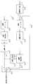
도 1은 본 발명의 바람직한 실시예에 따른 영상 부호화 시스템의 블록구성도,1 is a block diagram of a video encoding system according to a preferred embodiment of the present invention;
도 2는 본 발명의 바람직한 실시예에 따른 영상 복호화 시스템의 블록구성도,2 is a block diagram of an image decoding system according to a preferred embodiment of the present invention;
도 3은 본 발명에 따라 수신된 비트 스트림에서 에러가 검출될 때 검출된 전송에러의 복원을 위해 후보 블록을 생성하는 과정을 설명하기 위해 도시한 도면,3 is a view illustrating a process of generating a candidate block for recovery of a detected transmission error when an error is detected in a received bit stream according to the present invention;
도 4는 도 2에 도시된 영상 복원 블록의 세부 블록구성도,4 is a detailed block diagram of an image restoration block shown in FIG. 2;
도 5는 수신된 N×N 블록에서 에러가 발생했을 때 먼저 복호화된 주변 블록의 화소값을 이용하여 에러를 복원하는 과정을 설명하기 위해 도시한 프레임의 일부 절결도.FIG. 5 is a partially cutaway view of a frame illustrated to explain a process of recovering an error by using a pixel value of a neighboring block decoded first when an error occurs in a received N × N block;
<도면의 주요부분에 대한 부호의 설명><Description of the code | symbol about the principal part of drawing>
102 : DCT 블록 104 : 양자화 블록102: DCT block 104: quantization block
106 : VLC 블록 108 : 비트 분할/패리티 발생 블록106: VLC block 108: bit division / parity generation block
204 : 오류 검출 블록 206,214 : VLD 블록204: Error detection block 206,214: VLD block
208 : 양자화 블록 210 : IDCT 블록208
212 : 메모리 블록 216 : 후보 발생 블록212: memory block 216: candidate generation block
218 : 영상 복원 블록 220 : 스위칭 블록218: image restoration block 220: switching block
402 : 역양자화부 404 : IDCT 부402: inverse quantization unit 404: IDCT unit
406 : 경계값 산출 블록 408 : 후보 발생 블록406: Boundary value calculation block 408: Candidate generation block
410 : 메모리410: memory
본 발명의 상기 및 기타 목적과 여러가지 장점은 이 기술분야에 숙련된 사람들에 의해 첨부된 도면을 참조하여 하기에 기술되는 본 발명의 바람직한 실시예로 부터 더욱 명확하게 될 것이다.The above and other objects and various advantages of the present invention will become more apparent from the preferred embodiments of the present invention described below with reference to the accompanying drawings by those skilled in the art.
이하 첨부된 도면을 참조하여 본 발명의 바람직한 실시예에 대하여 상세하게 설명한다.Hereinafter, exemplary embodiments of the present invention will be described in detail with reference to the accompanying drawings.
본 발명의 핵심 기술요지는, 송신측(부호화 시스템)에서는 전술한 종래 방법에서와 같이 기설정된 N×N 블록 단위(예를들면, 8×8 블록)로 비트길이 정보를 부가하고 에러체크 및 복구를 위한 패리티 비트를 부가하는 것이 아니라, 압축 부호화된 영상 데이터를 기설정된 n 비트 단위(예를들면, 10 비트 단위)로 패리티 비트를 부가하여 전송하고, 수신측(복호화 시스템)에서는 기설정된 n 비트 단위로 패리티 비트가 부가된 수신 데이터에서 부가된 패리티 비트를 이용하여 에러를 검출하고 전송에러가 발생될 때 이전에 복원된 주변 블록 데이터의 인접 화소값을 이용하여 에러를 복구한다는 것이다.A key technical aspect of the present invention is that, on the transmitting side (encoding system), bit length information is added in predetermined N × N block units (eg, 8 × 8 blocks) as in the conventional method described above, and error checking and recovery are performed. Rather than adding parity bits for, the compressed and encoded image data is transmitted by adding parity bits in a predetermined n-bit unit (for example, 10-bit unit), and the preset n-bits are received on the receiving side (decoding system). The error is detected by using the added parity bit in the received data to which the parity bit is added as a unit, and when the transmission error occurs, the error is recovered by using the adjacent pixel value of the neighboring block data previously restored.
먼저, 본 발명에 따른 영상 부호화 시스템에서 디지탈 영상 데이터를 압축 부호화하고, 이 부호화된 데이터에 전송에러의 체크 및 복구를 위한 패리티 비트를 부가하는 동작과정에 설명한다.First, an operation process of compressing and encoding digital image data in the image encoding system according to the present invention and adding parity bits for checking and recovering transmission errors to the encoded data will be described.
도 1은 본 발명의 바람직한 실시예에 따른 영상 부호화 시스템의 블록구성도를 나타낸다. 동도면에 도시된 바와같이, 본 발명의 부호화 시스템은 DCT 블록(102), 양자화 블록(104), 가변길이 부호화 블록(VLC)(106) 및 비트 분할/패리티 발생 블록(108)을 포함한다.1 is a block diagram of a video encoding system according to a preferred embodiment of the present invention. As shown in the figure, the coding system of the present invention includes a
도 1을 참조하면, DCT 블록(102)에서는 도시 생략된 프레임 메모리에서 제공되는 디지탈 영상 데이터에 대해, 예를들면 직교변환에 의거하는 이산 코사인 변환을 수행하며, 그 변환의 결과로서 N×N DCT 변환계수 블록들을 발생하여 다음단의 양자화 블록(104)으로 제공한다.Referring to FIG. 1, in the
다음에, 양자화 블록(104)에서는, 기설정된 양자화 스텝 사이즈 또는 도시 생략된 출력측 버퍼에서 제공되는 버퍼 충만상태 정보에 의거하여 적응적으로 결정되는 양자화 스텝 사이즈에 의거하여, 상기한 DCT 블록(102)에서 제공되는 DCT 변환계수값들을 유한한 값을 갖는 양자화값으로 근사시켜 양자화된 DCT 변환계수들을 발생한다.Next, in the
또한, 가변길이 부호화 블록(106)에서는 데이터의 발생확률에 근거하여 상대적으로 발생확률이 높은 부호에는 짧은 부호를 할당하는 발생확률이 적은 부호에는 긴길이의 부호를 할당하는 기법으로, 입력 데이터를 가변길이 부호화하여 다음단의 비트 분할/패리티 발생 블록(108)으로 제공한다.In the variable
한편, 비트 분할/패리티 발생 블록(108)은, 본 발명의 부호화 시스템에서 가장 특징적인 부분을 이루는 것으로, 수신측(즉, 복호화 시스템)에서 전송중에 발생한 전송에러를 체크하고 또한 발생된 전송에러를 복구할 수 있도록 가변길이 부호화된 영상 데이터를 기설정된 n 비트 단위(예를들면, 10 비트 단위)로 분할하고, 이 분할된 각 n 비트 단위마다 패리티 비트(1 비트의 패리티 비트)를 부가하며, 이와같이 n 비트 단위로 패리티 비트가 부가된 부호 데이터들은 수신측으로의 전송을 위해 도시 생략된 전송채널로 송신된다. 물론, 본 발명에 따른 부호화 시스템에서 기설정된 부호화된 데이터의 비트 분할 단위는 수신측(즉, 복호화 시스템)과 사전에 미리 약속되어야 한다는 전제조건을 충족시켜야 할 것이다.On the other hand, the bit division /
즉, 전술한 종래 방법에서는, 예를들어, 사이즈가 256×256 인 영상신호에서 발생되는 부호화된 비트량이 25k 비트이고, 8×8 블록 단위로 구분하며 각 블록에 부여되는 비트길이 정보를 8 비트로 표현한다고 가정할 때, 한 화면분의 영상 데이터를 전송하는 데, 비트길이 정보가 대략 8k 비트, 실제 데이터가 25k 비트, 패리티 비트가 대략 1k 비트가 되므로 실제 전송해야 할 총 비트량은 대략 34k 비트가 되지만, 본 발명에 따라, 예를들어 10 비트 단위로 패리티 비트를 부가한다고 가정하면 실제 데이터 25k 비트, 패리티 비트 2.5k 비트가 되므로 실제 전송해야 할 총 비트량은 27.5k 비트가 된다.That is, in the above-described conventional method, for example, the coded bit amount generated in a video signal having a size of 256x256 is 25k bits, divided into 8x8 block units, and the bit length information given to each block is 8 bits. Assuming that the image data for one screen is transmitted, bit length information is approximately 8k bits, actual data is 25k bits, and parity bits are approximately 1k bits, so the total amount of bits to be transmitted is approximately 34k bits. However, according to the present invention, assuming parity bits are added in units of 10 bits, for example, the actual data is 25k bits and the parity bits 2.5k bits, so the total amount of bits to be transmitted is 27.5k bits.
따라서, 상기한 바로부터 알 수 있는 바와같이 n 비트 단위로 분할하여 패리티 비트만을 부가하는 본 발명에서는, N×N 블록 단위로 비트길이 정보 및 패리티 비트를 부가하는 종래 방법에 비해, 전송 데이터가 대략 6.5k 비트 정도 적게 발생된다.Therefore, as can be seen from the above, in the present invention in which only parity bits are added by dividing by n-bit units, the transmission data is approximately compared with the conventional method of adding bit length information and parity bits in N × N block units. Less than 6.5k bits are generated.
다음에, 상술한 바와같은 과정을 통해 전송에러의 체크 및 복구를 위한 패리티 비트가 부가된 부호화 데이터가 수신될 때 발생된 전송에러를 복구하면서 부호화전의 원신호로 복원하는 동작과정에 설명한다.Next, an operation process of restoring the transmission error generated when the encoded data to which the parity bit for the check and recovery of the transmission error is added through the above-described process is recovered, and recovering the original signal before encoding.
도 2는 본 발명의 바람직한 실시예에 따른 영상 복호화 시스템의 블록구성도를 나타낸다.2 is a block diagram of an image decoding system according to a preferred embodiment of the present invention.
동도면에 도시된 바와같이, 본 발명의 복호화 시스템은, 전송에러가 발생되지 않은 영상 데이터를 처리하는 경로와 전송에러가 발생된 영상 데이터를 처리하는 경로로 된 두 개의 복호화 경로를 구비하는 데, 오류 검출 블록(204), 제 1 가변길이 복호화 블록(VLD)(206), 역양자화 블록(208), IDCT 블록(210), 메모리 블록(212), 제 2 가변길이 복호화 블록(214), 후보 발생 블록(216), 영상 복원 블록(218) 및 스위칭 블록(220)을 포함한다.As shown in the figure, the decoding system of the present invention includes two decoding paths, which are paths for processing image data in which transmission errors have not occurred and paths for processing image data in which transmission errors have occurred. Error detection block 204, first variable length decoding block (VLD) 206,
도 2를 참조하면, 오류 검출 블록(204)에서는 라인 L21 상의 부호화된 입력 데이터, 즉 비트 스트림를 기설정된 n 비트 단위(예를들면, 10 비트)로 분할하여 전송에러의 발생여부를 체크, 즉 비트 스트림내에 n 비트 단위로 부가된 패리티 비트에 의거하여 전송에러의 발생을 체크하며, 전송에러의 발생이 검출될 때 복호화 경로 설정을 위한 제어신호, 예를들어 하이 또는 로우레벨의 논리신호인 경로 절환 제어신호를 라인 L24 상에 발생한다.Referring to FIG. 2, the error detection block 204 divides the coded input data on the line L21, that is, the bit stream, into a predetermined n bit unit (for example, 10 bits) to check whether a transmission error occurs, that is, bit. The occurrence of a transmission error is checked based on the parity bit added in units of n bits in the stream, and when a transmission error is detected, a control signal for setting a decoding path, for example, a path switching which is a logic signal of a high or low level. A control signal is generated on line L24.
즉, 오류 검출 블록(204)에서는 블록 종료 정보(End Of Block)에 의거하여 하나의 N×N 블록(예를들면, 8×8 블록) 단위의 비트 스트림을 입력받아 기설정된 n 비트 단위(예를들면, 10 비트 단위)로 부가된 패리티 비트를 이용하여 전송에러를 검출하는 데, 전송에러가 검출되지 않는 블록 데이터는 라인 L22를 통해 정상 블록 처리 경로로 출력, 즉 후술하는 제 1 VLD 블록(206)으로 제공하고, 전송에러가 검출된 블록 데이터는 라인 L23을 통해 에러 블록 처리 경로로 출력, 즉 제 2 VLD 블록(214)으로 제공한다. 또한, 오류 검출 블록(204)은 블록내에서 전송에러가 검출될 때 라인 L24 상에 그에 상응하는 절환 제어신호(예를들면, 하이 또는 로우레벨을 갖는 논리신호)를 발생한다.That is, the error detection block 204 receives a bit stream of one N × N block (for example, 8 × 8 block) based on block end information (End Of Block) and receives a predetermined n-bit unit (eg For example, a transmission error is detected using a parity bit added in units of 10 bits, and block data for which no transmission error is detected is output through a line L22 to a normal block processing path, that is, a first VLD block (to be described later). Block data for which a transmission error is detected is output to the error block processing path, that is, to the second VLD block 214 through the line L23. In addition, the error detection block 204 generates a corresponding switching control signal (e.g., a logic signal having a high or low level) on the line L24 when a transmission error is detected in the block.
다음에, 제 1 VLD 블록(206), 역양자화 블록(208) 및 IDCT 블록(210)으로 구성된 정상 블록 처리 경로는, 전송에러가 발생하지 않은 부호화된 블록 데이터를 처리, 즉 도 1에 도시된 부호화 시스템에서의 역과정을 수행하여 각 블록 데이터들을 부호화전의 원신호로 복원하는 것으로, 여기에서 복원되는 블록 데이터들은 라인 L25 상에 연결된 스위칭 블록(220)을 경유하여 도시 생략된 디스플레이측으로 제공됨과 동시에 후술하는 전송에러 복구에서의 이용을 위해 메모리 블록(212)에 저장된다.Next, the normal block processing path composed of the
이때, 전송에러의 복구를 위해 복원된 데이터를 저장하는 메모리 블록(212)은 한 프레임분의 데이터를 모두 저장하는 것이 아니라 에러 복구시에 실제적으로 필요로 하는 복원된 에러 복구용 블록 데이터, 즉 현재 복원 처리중인 블록이 존재하는 블록행의 이전 블록 데이터들과 이전 블록열의 블록 데이터들만을 저장한다. 즉, 도 5를 참조하면, 일예로서 현재 복원 처리되는 블록이 B2 블록인 경우라 가정하면 메모리 블록(212)에는 A 행의 모든 블록 데이터들(A1 내지 An)과 B1 블록 데이터가 저장되고, 현재 복원 처리되는 블록이 Bn 블록인 경우라 가정하면 메모리 블록(212)에는 A 행의 모든 블록 데이터들(A1 내지 An)과 B1 내지 Bn-1 블록 데이터가 저장될 것이다.In this case, the
즉, 메모리 블록(212)은 최대 두 행의 블록 데이터들을 순차 저장하는 데, 두 행의 블록 데이터들이 모두 저장된 상태에서 이어지는 다음 행의 첫번째 블록 데이터가 입력되면 먼저 저장되어 있던 이전 행의 블록 데이터들을 모두 버리는 방식(예를들어, A 및 B 행의 모든 블록 데이터(A1 내지 An 및 B1 내지 Bn)들이 저장된 상태에서 이어지는 C 행의 첫번째 블록(C1) 데이터가 입력되면 A행의 블록 데이터들을 버리는 방식)으로 에러 복구에 필요한 복원된 주변 블록 데이터들을 저장한다.That is, the
그러므로, 일예로서 B2 블록에서 에러가 발생한 경우 영상 복원 블록(218)에서는 메모리 블록(212)을 검색하여 인접하는 주변 블록인 A2 및 B1 블록 데이터를 인출하게 될 것이고, C3 블록에서 에러가 발생한 경우 메모리 블록(212)을 검색하여 인접하는 주변 블록인 B3 및 C2 블록 데이터를 인출하게 될 것이다. 이때, 이 기술분야에 이미 잘 알려진 일반적인 기술인 관계로 도 2에서의 상세한 도시는 생략하였으나, 메모리 블록(212)에서의 블록 데이터 저장 및 인출은, 예를들면 도시 생략된 마이크로 프로세서로부터 제공되는 기록 어드레스 신호 및 판독 어드레스 신호에 의거하여 실행되도록 구성될 수 있다.Therefore, as an example, when an error occurs in the B2 block, the
한편, 본 발명에 따라 구비되는 에러 블록 처리 경로를 이루는 제 2 VLD 블록(214)은 전술한 라인 L23을 통해 오류 검출 블록(204)으로부터 제공되는 전송에러가 발생된 비트 스트림 형태의 블록 데이터를 입력으로 하여, 상기한 제 1 VLD 블록(206)에서와 마찬가지로 가변길이 복호화를 수행하는 것으로, 가변길이 복호화된 출력 데이터는 다음단의 후보 발생 블록(216)으로 제공된다.Meanwhile, the second VLD block 214 constituting the error block processing path provided in accordance with the present invention inputs block data in the form of a bit stream in which a transmission error is provided from the error detection block 204 through the above-described line L23. In this case, variable length decoding is performed as in the
또한, 후보 발생 블록(216)은 n 비트 단위로 패리티 비트가 부가된 블록 데이터에서 전송에러가 발생된 n 비트 단위 데이터의 데이터 복구를 위해 다수의 후보 블록을 생성, 예를들어 10 비트 단위의 비트군으로 분할되어 패리티 비트가 부가된 것이라고 가정할 때, 일예로서 도 3에 도시된 바와같이, 최상위 비트부터 최하위 비트까지 차례로 한 비트씩 반전시킨 10개의 후보 비트군을 각각 포함하는 다수의 후보 블록을 생성하여 라인 L27 상에 발생한다. 즉, 도 3a는 최상위 비트값(a1)을 반전시켜 구성한 후보 비트군이고, 도 3b는 두 번째 비트값(a2)을 반전시켜 구성한 후보 비트군이며, 도 3c는 최하위 비트값(a10)을 반전시켜 구성한 후보 비트군이다.In addition, the
다음에, 영상 복원 블록(218)은 상기한 후보 발생 블록(216)을 통해 생성된 각 후보 비트군을 포함하는 후보 블록 데이터를 부호화전의 원신호로 복원, 즉 역양자화 및 IDCT 과정을 통해 원신호로 복원하며, 여기에서 복원된 각 후보 블록 데이터는 스위칭 블록(220)의 가변접점 c에 연결된다.Next, the
또한, 영상 복원 블록(218)에서는 하나의 n 비트 후보 비트군을 각각 포함하는 다수의 블록 데이터들의 각 화소값과 메모리 블록(212)에서 제공되는 전송에러가 발생된 블록의 주변 블록의 화소값에 의거하여 다수의 후보 블록들중 최종 복원 블록을 결정하는 데, 실질적으로 이와같이 결정되는 최종 복원 블록이 스위칭 블록(220)의 가변접점 c로 출력된다. 이러한 영상 복원 블록(218)에서의 구체적인 동작과정에 대해서는 그 세부적인 블록구성을 도시한 도 4를 참조하여 후에 상세하게 기술한다.Also, in the
이때, 스위칭 블록(220)은 라인 L24를 통해 전술한 오류 검출 블록(204)으로부터 제공되는 절환 제어신호에 응답하여 그 접점을 절환, 즉 전송에러가 검출되지 않을 때 접점 a-b를 연결하고, 전송에러가 검출될 때 접점 a-c를 연결하며, 이러한 스위칭 블록(220)을 통해 적응적으로 출력되는 블록 데이터 또는 전송에러가 복구된 데이터들은 모니터로의 디스플레이를 위해 도시 생략된 디스플레이측으로 제공된다.At this time, the switching block 220 switches the contact in response to the switching control signal provided from the above-described error detection block 204 through the line L24, that is, connects the contact ab when a transmission error is not detected, and transmits a transmission error. The contact ac is connected when is detected, and the block data adaptively output through the switching block 220 or the data from which the transmission error is recovered are provided to the display side, not shown, for display on the monitor.
도 4는 본 발명에 따른 영상 복호화 시스템을 보여주는 도 2에 도시된 영상 복원 블록의 세부적인 블록구성도로서, 역양자화부(402), IDCT 부(404), 경계값 산출 블록(406), 후보 결정 블록(408) 및 메모리(410)를 포함한다.FIG. 4 is a detailed block diagram of the image reconstruction block shown in FIG. 2 showing an image decoding system according to the present invention, including an
도 4를 참조하면, 역양자화부(402) 및 IDCT 부(404)는, 라인 L27 상의 후보 블록 데이터들, 즉 n 비트 후보 비트군을 각각 포함하는 다수의 후보 블록들을, 전술한 도 2의 역양자화 블록(208) 및 IDCT 블록(210)에서와 마찬가지로 부호화전의 원신호로 각각 복원하는 것으로, 여기에서 복원된 각 후보 블록 데이터들은 라인 L41을 통해 경계값 산출 블록(406) 및 메모리(410)로 각각 제공된다.Referring to FIG. 4, the
이때, 메모리(410)로 제공되는 각 후보 블록 데이터들은 소정의 어드레스에 각각 저장되는 데, 라인 L43을 통해 후술하는 후보 결정 블록(408)으로부터 제공되는 블록 결정신호에 의거하여 저장된 다수의 후보 블록들중 하나가 최종 복원 블록(발생된 전송에러가 복구된 블록)으로 결정되어 라인 L28을 통해 인출될 것이다.In this case, each of the candidate block data provided to the
다음에, 경계값 산출 블록(406)에서는 라인 L41을 통해 제공되는 각 후보 블록들 각각에 대해 이전에 복원된 주변 블록과 인접하는 화소값들과 라인 L26을 통해 도 2의 메모리 블록(212)으로부터 제공되는 주변 블록 화소값(즉, 후보 블록에 인접하는 화소값들)들간의 경계값을 각각 산출한다.Next, in the boundary
일예로서 도 5에 도시된 바와같이, 전송에러가 발생한 블록이 B2 블록이라고 가정할 때 B2 블록에 대응하여 발생된 다수의 후보 블록(예를들면, 10개) 각각에 대해, 각 후보 블록의 b21 영역의 각 화소값들(예를들어, 8×8 DCT 블록일 때 8개의 화소값)에 인접하는 주변 블록 A2의 a2 영역의 각 화소값들과 각 후보 블록 b22 영역의 각 화소값들과 인접하는 주변 블록 B1 의 b1 영역의 각 화소값들간의 자승오차값을 각각 산출한다.As an example, as shown in FIG. 5, assuming that a block in which a transmission error occurs is a B2 block, b21 of each candidate block for each of a plurality of candidate blocks (eg, 10) generated corresponding to the B2 block. Adjacent pixel values of the a2 region of the peripheral block A2 adjacent to each pixel value of the region (for example, 8 pixel values in an 8x8 DCT block) and adjacent pixel values of the candidate block b22 region. The squared error values between the pixel values in the b1 region of the neighboring block B1 are calculated.
여기에서, 자승오차값은 후보 블록의 경계 화소값과과 이에 대응하는 두 개의 주변 블록의 경계 화소값들에 각각 자승을 취한 다음 얻은 차값인 것으로, 하나의 후보 블록과 이에 대응하는 두 개의 주변 블록간의 자승오차값은, 예를들어 각 블록이 8×8 블록이고 후보 블록이 도 5의 B2 블록에 대응하는 후보 블록이라 가정할 때, B2 블록의 상측 경계 화소값 8개와 이에 대응하는 A2 블록의 하측 경계 화소값 8개간에 각각 산출되는 8개의 차값과 B2 블록의 좌측 경계 화소값 8개와 이에 대응하는 B1 블록의 우측 경계 화소값 8개간에 각각 산출되는 8개의 차값, 즉 모두 16개가 될 것이다.Here, the squared error value is a difference value obtained by taking a square of the boundary pixel value of the candidate block and the boundary pixel values of two neighboring blocks corresponding to each other, and between one candidate block and two corresponding neighboring blocks. The squared error value is, for example, assuming that each block is an 8x8 block and the candidate block is a candidate block corresponding to the B2 block of FIG. 5, the lower boundary of the eight upper boundary pixel values of the B2 block and the corresponding A2 block. Eight difference values calculated between eight boundary pixel values and eight left boundary pixel values of the B2 block and eight right boundary pixel values of the corresponding B1 block, respectively, will be sixteen.
즉, 경계값 산출 블록(406)에서는 후보 블록이 10개인 경우, 10개의 각 후보 블록들 각각에 대해 16개의 자승오차값을 각각 산출하여 다음단의 후보 결정 블록(408)으로 제공한다.That is, in the case of 10 candidate blocks, the threshold
다음에, 후보 결정 블록(408)에서는, 대응하는 경계 화소들간의 자승오차값에 의거하여 다수의 후보 블록들중 최적 복원 블록을 결정, 다수의 각 후보 블록들에 대해 각각 산출된 각 후보 블록들의 대응하는 경계 화소간 자승오차값을 각각 가산하여 각 후보 블록들에 대한 다수의 자승오차 총합값을 생성하며, 이와같이 생성된 자승오차 총합값중 가장 작은 자승오차 총합값을 갖는 후보 블록을 에러 발생 블록의 최종 복원 블록으로 결정하기 위한 블록 결정신호를 라인 L43 상에 발생한다. 이때, 발생되는 라인 L43 상의 블록 결정신호는, 예를들면 소정 어드레스에 저장된 후보 블록 데이터를 인출하기 위한 판독 인에이블 신호이다.Next, the
따라서, 메모리(410)에서는 소정의 어드레스에 각각 저장된 다수의 후보 블록들중 라인 L43 상의 블록 결정신호에 의해 인출이 선택된 후보 블록이 라인 L28을 통해 출력되어 도 2의 스위칭 블록(220)으로 제공된다.Accordingly, in the
그 결과, 도 2의 스위칭 블록(220)에서는 라인 L24를 통해 오류 검출 블록(204)으로부터 제공되는 절환 제어신호에 의거하여 전송에러가 발생하지 않은 복원 블록 데이터 또는 발생된 전송에러가 복구된 복원 블록 데이터의 출력을 적응적으로 선택하여 도시 생략된 디스플레이측으로 제공한다.As a result, in the switching block 220 of FIG. 2, the restoring block data in which no transmission error occurs or the restoring block in which the transmission error has been recovered based on the switching control signal provided from the error detection block 204 through the line L24. The output of data is adaptively selected and provided to the display side, not shown.
이상 설명한 바와같이 본 발명에 따르면, 전송에러의 체크 및 복구를 위하여 압축 부호화된 영상 데이터에 대해 블록 단위가 아닌 기설정된 n 비트 단위로 패리티 비트만을 부가하여 전송함으로써, 블록 단위로 패리티 비트 및 비트길이 정보를 부가하여 전송하는 종래 방법에 비해 그 비트발생량을 효과적으로 억제할 수 있고, 또한 전송에러 발생시 이전에 복원된 주변 블록의 대응하는 경계 화소값들을 이용하여 전송에러를 효과적으로 복구함으로써 복원 영상의 화질열화를 최소화할 수 있다.As described above, according to the present invention, parity bits and bit lengths are transmitted in block units by adding and transmitting only parity bits in a predetermined n bit unit instead of block units to compressed coded image data for checking and recovering transmission errors. Compared with the conventional method of adding and transmitting information, the bit generation amount can be suppressed more effectively, and when a transmission error occurs, image quality deterioration of the reconstructed image can be effectively recovered by effectively recovering the transmission error using the corresponding boundary pixel values of the neighboring block that was previously restored. Can be minimized.
Claims (8)
Translated fromKoreanPriority Applications (1)
| Application Number | Priority Date | Filing Date | Title |
|---|---|---|---|
| KR1019970027164AKR100245037B1 (en) | 1997-06-25 | 1997-06-25 | Improved image encoding/decoding system and error recovery method thereof |
Applications Claiming Priority (1)
| Application Number | Priority Date | Filing Date | Title |
|---|---|---|---|
| KR1019970027164AKR100245037B1 (en) | 1997-06-25 | 1997-06-25 | Improved image encoding/decoding system and error recovery method thereof |
Publications (2)
| Publication Number | Publication Date |
|---|---|
| KR19990003313A KR19990003313A (en) | 1999-01-15 |
| KR100245037B1true KR100245037B1 (en) | 2000-02-15 |
Family
ID=19511127
Family Applications (1)
| Application Number | Title | Priority Date | Filing Date |
|---|---|---|---|
| KR1019970027164AExpired - Fee RelatedKR100245037B1 (en) | 1997-06-25 | 1997-06-25 | Improved image encoding/decoding system and error recovery method thereof |
Country Status (1)
| Country | Link |
|---|---|
| KR (1) | KR100245037B1 (en) |
- 1997
- 1997-06-25KRKR1019970027164Apatent/KR100245037B1/ennot_activeExpired - Fee Related
Also Published As
| Publication number | Publication date |
|---|---|
| KR19990003313A (en) | 1999-01-15 |
Similar Documents
| Publication | Publication Date | Title |
|---|---|---|
| US7085424B2 (en) | Method and system for compressing motion image information | |
| US7486833B2 (en) | System and program product for error recovery while decoding cached compressed data | |
| JP3888597B2 (en) | Motion compensation coding apparatus and motion compensation coding / decoding method | |
| ES2328916T3 (en) | TRANSFORMATION COEFFICIENTS OF CODING IN CODERS AND / OR IMAGE / VIDEO DECODERS. | |
| CN102104764B (en) | Method for compressing, storing and processing image sequence | |
| JP6049017B2 (en) | Video transmission system with reduced memory requirements | |
| JP2009260977A (en) | Video data compression using combination of irreversible compression and reversible compression | |
| JP4801778B2 (en) | Video compression / encoding device, video restoration device, video compression program, and video restoration program | |
| JP3918263B2 (en) | Compression encoding apparatus and encoding method | |
| JPH09327019A (en) | Object area coding device | |
| AU2002230101A2 (en) | Moving picture information compressing method and its system | |
| KR100245037B1 (en) | Improved image encoding/decoding system and error recovery method thereof | |
| US20080056585A1 (en) | Image processing method for facilitating data transmission | |
| CN100399833C (en) | High-speed image compression device using last non-zero detection circuit | |
| KR100385620B1 (en) | Improved MPEG coding method, moving picture transmitting system and method thereof | |
| KR20100082700A (en) | Wyner-ziv coding and decoding system and method | |
| JPH05284369A (en) | Image data encoding / restoring method and apparatus thereof | |
| EP1453322A1 (en) | Moving picture information compression method and system thereof | |
| KR100207391B1 (en) | Image coding system and moving information detecting method using adaptive vector quantization | |
| JP2820718B2 (en) | Image coding device | |
| KR100235065B1 (en) | IMAGE DECODER HAVING FUNCTIONS FOR RECONSTRUCTING BITS ERROR | |
| JPH04269084A (en) | Image converter | |
| JPH07131794A (en) | Image data encoding method and apparatus | |
| JP3200073B2 (en) | Image processing device | |
| EP0921686A1 (en) | Device and method for iterative conversion encoding of images, device and method for iterative conversion decoding of images, and providing medium |
Legal Events
| Date | Code | Title | Description |
|---|---|---|---|
| A201 | Request for examination | ||
| PA0109 | Patent application | St.27 status event code:A-0-1-A10-A12-nap-PA0109 | |
| PA0201 | Request for examination | St.27 status event code:A-1-2-D10-D11-exm-PA0201 | |
| R17-X000 | Change to representative recorded | St.27 status event code:A-3-3-R10-R17-oth-X000 | |
| PG1501 | Laying open of application | St.27 status event code:A-1-1-Q10-Q12-nap-PG1501 | |
| E902 | Notification of reason for refusal | ||
| PE0902 | Notice of grounds for rejection | St.27 status event code:A-1-2-D10-D21-exm-PE0902 | |
| P11-X000 | Amendment of application requested | St.27 status event code:A-2-2-P10-P11-nap-X000 | |
| P13-X000 | Application amended | St.27 status event code:A-2-2-P10-P13-nap-X000 | |
| E701 | Decision to grant or registration of patent right | ||
| PE0701 | Decision of registration | St.27 status event code:A-1-2-D10-D22-exm-PE0701 | |
| GRNT | Written decision to grant | ||
| PR0701 | Registration of establishment | St.27 status event code:A-2-4-F10-F11-exm-PR0701 | |
| PR1002 | Payment of registration fee | St.27 status event code:A-2-2-U10-U11-oth-PR1002 Fee payment year number:1 | |
| PG1601 | Publication of registration | St.27 status event code:A-4-4-Q10-Q13-nap-PG1601 | |
| R18-X000 | Changes to party contact information recorded | St.27 status event code:A-5-5-R10-R18-oth-X000 | |
| R18-X000 | Changes to party contact information recorded | St.27 status event code:A-5-5-R10-R18-oth-X000 | |
| PR1001 | Payment of annual fee | St.27 status event code:A-4-4-U10-U11-oth-PR1001 Fee payment year number:4 | |
| PN2301 | Change of applicant | St.27 status event code:A-5-5-R10-R11-asn-PN2301 | |
| PN2301 | Change of applicant | St.27 status event code:A-5-5-R10-R11-asn-PN2301 | |
| PN2301 | Change of applicant | St.27 status event code:A-5-5-R10-R14-asn-PN2301 | |
| PR1001 | Payment of annual fee | St.27 status event code:A-4-4-U10-U11-oth-PR1001 Fee payment year number:5 | |
| PR1001 | Payment of annual fee | St.27 status event code:A-4-4-U10-U11-oth-PR1001 Fee payment year number:6 | |
| PR1001 | Payment of annual fee | St.27 status event code:A-4-4-U10-U11-oth-PR1001 Fee payment year number:7 | |
| PR1001 | Payment of annual fee | St.27 status event code:A-4-4-U10-U11-oth-PR1001 Fee payment year number:8 | |
| PR1001 | Payment of annual fee | St.27 status event code:A-4-4-U10-U11-oth-PR1001 Fee payment year number:9 | |
| PR1001 | Payment of annual fee | St.27 status event code:A-4-4-U10-U11-oth-PR1001 Fee payment year number:10 | |
| PR1001 | Payment of annual fee | St.27 status event code:A-4-4-U10-U11-oth-PR1001 Fee payment year number:11 | |
| PR1001 | Payment of annual fee | St.27 status event code:A-4-4-U10-U11-oth-PR1001 Fee payment year number:12 | |
| PR1001 | Payment of annual fee | St.27 status event code:A-4-4-U10-U11-oth-PR1001 Fee payment year number:13 | |
| FPAY | Annual fee payment | Payment date:20121101 Year of fee payment:14 | |
| PR1001 | Payment of annual fee | St.27 status event code:A-4-4-U10-U11-oth-PR1001 Fee payment year number:14 | |
| L13-X000 | Limitation or reissue of ip right requested | St.27 status event code:A-2-3-L10-L13-lim-X000 | |
| U15-X000 | Partial renewal or maintenance fee paid modifying the ip right scope | St.27 status event code:A-4-4-U10-U15-oth-X000 | |
| FPAY | Annual fee payment | Payment date:20131101 Year of fee payment:15 | |
| PR1001 | Payment of annual fee | St.27 status event code:A-4-4-U10-U11-oth-PR1001 Fee payment year number:15 | |
| R18-X000 | Changes to party contact information recorded | St.27 status event code:A-5-5-R10-R18-oth-X000 | |
| LAPS | Lapse due to unpaid annual fee | ||
| PC1903 | Unpaid annual fee | St.27 status event code:A-4-4-U10-U13-oth-PC1903 Not in force date:20141126 Payment event data comment text:Termination Category : DEFAULT_OF_REGISTRATION_FEE | |
| PC1903 | Unpaid annual fee | St.27 status event code:N-4-6-H10-H13-oth-PC1903 Ip right cessation event data comment text:Termination Category : DEFAULT_OF_REGISTRATION_FEE Not in force date:20141126 | |
| P22-X000 | Classification modified | St.27 status event code:A-4-4-P10-P22-nap-X000 |