KR100236536B1 - Modulo address generator and its method - Google Patents
Modulo address generator and its methodDownload PDFInfo
- Publication number
- KR100236536B1 KR100236536B1KR1019970000420AKR19970000420AKR100236536B1KR 100236536 B1KR100236536 B1KR 100236536B1KR 1019970000420 AKR1019970000420 AKR 1019970000420AKR 19970000420 AKR19970000420 AKR 19970000420AKR 100236536 B1KR100236536 B1KR 100236536B1
- Authority
- KR
- South Korea
- Prior art keywords
- address value
- value
- address
- minimum
- maximum
- Prior art date
- Legal status (The legal status is an assumption and is not a legal conclusion. Google has not performed a legal analysis and makes no representation as to the accuracy of the status listed.)
- Expired - Fee Related
Links
Images

Classifications
- G—PHYSICS
- G06—COMPUTING OR CALCULATING; COUNTING
- G06F—ELECTRIC DIGITAL DATA PROCESSING
- G06F15/00—Digital computers in general; Data processing equipment in general
- G06F15/76—Architectures of general purpose stored program computers
- G06F15/78—Architectures of general purpose stored program computers comprising a single central processing unit
- G—PHYSICS
- G06—COMPUTING OR CALCULATING; COUNTING
- G06F—ELECTRIC DIGITAL DATA PROCESSING
- G06F5/00—Methods or arrangements for data conversion without changing the order or content of the data handled
- G06F5/06—Methods or arrangements for data conversion without changing the order or content of the data handled for changing the speed of data flow, i.e. speed regularising or timing, e.g. delay lines, FIFO buffers; over- or underrun control therefor
- G06F5/10—Methods or arrangements for data conversion without changing the order or content of the data handled for changing the speed of data flow, i.e. speed regularising or timing, e.g. delay lines, FIFO buffers; over- or underrun control therefor having a sequence of storage locations each being individually accessible for both enqueue and dequeue operations, e.g. using random access memory
- G—PHYSICS
- G06—COMPUTING OR CALCULATING; COUNTING
- G06F—ELECTRIC DIGITAL DATA PROCESSING
- G06F7/00—Methods or arrangements for processing data by operating upon the order or content of the data handled
- G06F7/60—Methods or arrangements for performing computations using a digital non-denominational number representation, i.e. number representation without radix; Computing devices using combinations of denominational and non-denominational quantity representations, e.g. using difunction pulse trains, STEELE computers, phase computers
- G06F7/72—Methods or arrangements for performing computations using a digital non-denominational number representation, i.e. number representation without radix; Computing devices using combinations of denominational and non-denominational quantity representations, e.g. using difunction pulse trains, STEELE computers, phase computers using residue arithmetic
- G—PHYSICS
- G06—COMPUTING OR CALCULATING; COUNTING
- G06F—ELECTRIC DIGITAL DATA PROCESSING
- G06F9/00—Arrangements for program control, e.g. control units
- G06F9/06—Arrangements for program control, e.g. control units using stored programs, i.e. using an internal store of processing equipment to receive or retain programs
- G06F9/30—Arrangements for executing machine instructions, e.g. instruction decode
- G06F9/34—Addressing or accessing the instruction operand or the result ; Formation of operand address; Addressing modes
- G06F9/355—Indexed addressing
- G06F9/3552—Indexed addressing using wraparound, e.g. modulo or circular addressing
- G—PHYSICS
- G06—COMPUTING OR CALCULATING; COUNTING
- G06F—ELECTRIC DIGITAL DATA PROCESSING
- G06F2205/00—Indexing scheme relating to group G06F5/00; Methods or arrangements for data conversion without changing the order or content of the data handled
- G06F2205/10—Indexing scheme relating to groups G06F5/10 - G06F5/14
- G06F2205/106—Details of pointers, i.e. structure of the address generators
Landscapes
- Engineering & Computer Science (AREA)
- Theoretical Computer Science (AREA)
- Physics & Mathematics (AREA)
- General Physics & Mathematics (AREA)
- General Engineering & Computer Science (AREA)
- Mathematical Optimization (AREA)
- Computational Mathematics (AREA)
- Mathematical Analysis (AREA)
- Software Systems (AREA)
- Pure & Applied Mathematics (AREA)
- Computing Systems (AREA)
- Mathematical Physics (AREA)
- Computer Hardware Design (AREA)
- Error Detection And Correction (AREA)
- Compression, Expansion, Code Conversion, And Decoders (AREA)
- Complex Calculations (AREA)
Abstract
Translated fromKoreanDescription
Translated fromKorean본 발명은 모듈로 주소발생기 및 그 방법에 관한 것으로서, 특히 고속 디지탈 신호 처리기(Digital signal processor)의 모듈로 주소지정(Modulo Addressing) 로직에 있어서, 다단의 덧셈 연산을 거치지 않게 하여 덧셈 연산에 대한 짧은 지연시간을 갖고 고속의 가산기를 사용하는데에 따른 칩상에서의 차지하는 면적에 대한 오버헤드를 고려하여 가격 및 칩상에서 차지하는 면적 측면에서 보다 유효하게 모듈로 주소지정을 실현할 수 있는 고속 디지탈 신호 처리기의 모듈로 주소발생기 및 그 방법에 관한 것이다.BACKGROUND OF THE
일반적으로 디지탈 신호 처리기에서는 필터 등의 디지탈 신호 처리 알고리즘(digital signal processing algorithm)을 유효하게 구현하기 위해 모듈로 주소지정(modulo addressing)방식이 사용된다.In general, a modulo addressing method is used in a digital signal processor to effectively implement a digital signal processing algorithm such as a filter.
이러한 모듈로 주소지정(Modulo addressing)방식은 순환 주소지정(circular addressing)방식이라고도 하는데, 이의 가장 간단한 형태는 주소가 하나씩 증가하여 정해진 최대 주소(Maximum address)에 이르면 그 다음 주소는 최소 주소(Base address)가 되어 동일한 범위의 주소를 반복적으로 억세스(access)할 수 있게 한다.This modulo addressing method is also called circular addressing method. The simplest form of this is that the address is incremented one by one until the maximum address is reached and the next address is the base address. ) To allow repeated access to the same range of addresses.
상기와 같은 모듈로 주소지정방식은 필터 계수 등의 데이터가 특정 영역에 위치해 있을 때 오버헤드(overhead)없이 이들 데이터를 반복적으로 사용할 수 있게 해주어 디지탈 신호 처리 알고리즘을 빠르게 구현할 수 있도록 해주는 것이며, 이때 주소는 반드시 하나씩 증가할 필요는 없으며 또한 음수일 수도 있다.The modular addressing method as described above enables the digital signal processing algorithm to be quickly implemented by using these data repeatedly without overhead when data such as filter coefficients are located in a specific area. Is not necessarily incremented one by one and may also be negative.
좀더 일반적인 모듈로 주소지정(modulo addressing)은 다음과 같이 나타낼 수 있다.A more general modulo addressing can be written as
현재의 주소를 A, 주소 증가분을 I, 지정된 영역에서의 최대 주소를 M, 최소 주소를 B라고 가정할 때 다음에 지정될 주소 NEXT_A는 다음과 같이 정의된다.Assuming that the current address is A, the address increment is I, the maximum address in the specified area is M, and the minimum address is B, the next address NEXT_A is defined as follows.
먼저, 주소 증가분(I)이 I ≥ 0인 경우 현재의 주소(A)와 주소 증가분(I)을 더한 값이 최대 주소(M)보다 작으면((A + I) ≤ M) 다음에 지정될 주소(NEXT_A)는First, if the address increment (I) is I ≥ 0, then the current address (A) plus the address increment (I) is less than the maximum address (M) ((A + I) ≤ M). The address NEXT_A
NEXT_A = A + INEXT_A = A + I
로 되고, 반대로 현재의 주소(A)와 주소 증가분(I)을 더한 값이 최대 주소(M)보다 크면((A + I) > M) 다음에 지정될 주소(NEXT_A)는Conversely, if the current address (A) plus the address increment (I) is greater than the maximum address (M) ((A + I)> M), the next address (NEXT_A) to be specified is
NEXT_A = A + I - (M - B +1)NEXT_A = A + I-(M-B +1)
로 된다.It becomes
그리고, 주소 증가분(I)이 I < 0인 경우 현재의 주소(A)와 주소 증가분(I)을 더한 값이 최소 주소(B)보다 크면((A + I) ≥ B) 다음에 지정될 주소(NEXT_A)는If the address increment (I) is I <0, and the current address (A) plus the address increment (I) is greater than the minimum address (B) ((A + I) ≥ B), the address to be specified next (NEXT_A) is
NEXT_A = A + INEXT_A = A + I
로 되고, 반대로 현재의 주소(A)와 주소 증가분(I)을 더한 값이 최소 주소(B)보다 작으면((A + I) < B) 다음에 지정될 주소(NEXT_A)는Conversely, if the current address (A) plus the address increment (I) is less than the minimum address (B) ((A + I) <B), the next address (NEXT_A) to be specified is
NEXT_A = A + I + (M - B +1)……식(1)NEXT_A = A + I + (M-B +1)... … Formula (1)
로 된다. 단, 이때 B ≤ A ≤ M이고 I < M - B + 1 의 관계가 성립해야 한다.It becomes In this case, B ≤ A ≤ M and I <M-B + 1 should be established.
그런데 상기와 같은 (식 1)을 로직으로 구현하기 위해서는 수개의 가산기를 직렬로 연결하여 구성되는 다단의 덧셈 로직이 필요하며, 따라서 몇단의 덧셈을 순차적으로 거치면 고속으로 동작하는 디지탈 신호 처리기에서는 모듈로 주소지정 부분이 임계 경로(critical path)가 될 위험성이 있었다.However, in order to implement the above equation (1) as logic, multi-stage addition logic composed of several adders connected in series is required. Therefore, a digital signal processor operating at a high speed by sequentially adding several stages is used as a module. There was a risk that the addressing part would become a critical path.
따라서 상기와 같은 다단의 덧셈 로직을 피하기 위해 종래 일부 디지탈 신호 처리기에서는 고속의 가산기를 사용하여 도 1과 같은 모듈로 주소지정 로직을 구성하였다.Therefore, in order to avoid the multi-stage addition logic as described above, some conventional digital signal processors use a high speed adder to configure addressing logic as a module as shown in FIG. 1.
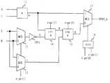
도 1은 현재의 주소(A)와 주소 증가분(I)을 더하여 출력하는 제1 가산기(11)와, 최대 주소(M)나 최소 주소(B)중의 하나를 주소 증가분(I)이 갖는 부호(sign(I))에 따라 선택하여 출력하는 두 개의 입력 선택기(12)(13)와, 상기 제1 입력 선택기의 출력을 반전시키는 인버터(INV)와, 상기 제1 가산기의 출력(a)과 상기 인버터의 출력(b)을 더하여 출력하는 제2 가산기(14)와, 상기 제2 가산기의 출력(d)과 상기 제2 입력 선택기의 출력(c)을 더하여 출력하는 제3 가산기(15)와, 상기 제1 가산기의 출력(a)과 제3 가산기의 출력(e)을 주소 증가분이 갖는 부호(sign(I))와 제2 가산기 출력이 갖는 부호(sign(d))에 대한 배타적 노어 게이트(16)의 논리결과에 따라 선택하여 출력하는 출력 선택기(17)로 구성하고 있다.1 shows a
즉, 상기 식(1)을 다시 쓰면 I ≥ 0 이고 A + I > M 일 때 다음에 지정될 주소(NEXT_A)는In other words, if I ≥ 0 and A + I> M, the next address (NEXT_A) to be specified is
NEXT_A = A + I - (M - B +1)NEXT_A = A + I-(M-B +1)
= A + I - M + B - 1= A + I-M + B-1
= A + I + inv(M) + B= A + I + inv (M) + B
로 되고, 여기서 inv(M)은 M의 보수(complement)를 나타내며, 그리고 상기 A + I > M 의 관계식은 A + I + inv(M) ≥ 0으로 다시 기술할 수 있게 된다.Where inv (M) represents the complement of M, and the relation A + I> M can be described again as A + I + inv (M)> 0.
마찬가지로 I < 0 이고 A + I < B 일 때 다음에 지정될 주소(NEXT_A)는Similarly, when I <0 and A + I <B, the next address to be assigned (NEXT_A) is
NEXT_A = A + I + (M - B +1)NEXT_A = A + I + (M-B +1)
= A + I + inv(B) + 1 + M + 1= A + I + inv (B) + 1 + M + 1
로 되고, 여기서 inv(B)는 B의 보수를 나타내며, 그리고 상기 A + I < B 는 A + I + inv(B) < 0으로 다시 기술할 수 있다.Where inv (B) represents the complement of B, and A + I <B can be described again as A + I + inv (B) <0.
위와 같은 방법을 사용하면 식(1)은 다음과 같이 바꿔 쓸수 있다.Using the above method, equation (1) can be rewritten as
a = A + Ia = A + I
b = inv(M)(sign(I) = 0일때)b = inv (M) when sign (I) = 0
= inv(B)(sign(I) ≠ 0일때)= inv (B) (when sign (I) ≠ 0)
c = B (sign(I) = 0일때)c = B (when sign (I) = 0)
= M (sign(I) ≠ 0일때)= M (when sign (I) ≠ 0)
d = a + b + sign(I)d = a + b + sign (I)
e = d + c + sign(I)e = d + c + sign (I)
NEXT_A = a (sign(I) xnor sign(d) = 1일 때)NEXT_A = a (when sign (I) xnor sign (d) = 1)
e (sign(I) xnor sign(d) ≠ 1일 때) ……식(2)e (when sign (I) xnor sign (d) ≠ 1). … Formula (2)
여기서 sign(I)와 sign(d)는 각각 I와 d의 부호 비트를 나타낸다.Where sign (I) and sign (d) represent the sign bits of I and d, respectively.
이와 같은 방법을 사용하면 별도의 비교기가 없이 3개의 가산기와 약간의 로직회로만으로 모듈로 주소지정을 구현할 수 있어 칩상에서 차지하는 영역 사용 측면에서 유리해 보인다.Using this approach, modular addressing can be implemented using only three adders and a few logic circuits without a separate comparator, which is advantageous in terms of using the area occupied on the chip.
그러나 "SGS-Thomson의 D950 core"등에서 사용된 이 방법은 고속의 디지탈 신호 처리기에 적용할 때에는 3개의 직렬로 연결된 가산기가 임계 경로(critical path)를 구성할 수 있으며, 이를 피하기 위해 캐리선택 가산기 등의 고속 가산기를 사용할 경우에는 칩상에서 차지하는 면적 측면에서도 유리하지 않은 문제점이 있었다.However, this method used in "SGS-Thomson's D950 core", etc., when applied to a high-speed digital signal processor, three serially connected adders can form a critical path, in order to avoid the carry selection adder, etc. In the case of using a high speed adder, there was a problem in that the area occupied on the chip was not advantageous.
따라서 본 발명의 목적은 상술한 종래 기술의 문제점을 해결하기 위하여 고속의 DSP칩에 적용하기 적합한 모듈로 주소발생기 및 그 방법을 제공하는 데 있다.Accordingly, an object of the present invention is to provide an address generator and a method thereof as a module suitable for application to a high-speed DSP chip in order to solve the problems of the prior art described above.
상기 목적을 달성하기 위한 본 발명의 장치는 현재 주소값과 주소 증가분을 가산하여 다음 주소값을 발생하는 제 1 가산기; 최대 주소값의 보수값과 최소 주소값를 가산하여 순환보정값을 발생하는 제 2 가산기; 상기 주소 증가분의 부호값에 따라 상기 순환보정값과 상기 다음 주소값을 가감산하여 보정된 다음 주소값을 발생하는 가감산기; 상기 다음 주소값이 상기 최대 주소값과 상기 최소 주소값 사이에 있는지를 판단하는 비교기; 상기 비교기의 출력에 따라 상기 다음 주소값이 상기 최대 주소값과 최소 주소값의 사이에 존재할 경우에는 상기 다음 주소값을 선택하고, 상기 다음 주소값이 상기 최대 주소값과 최소 주소값의 사이를 벗어날 경우에는 상기 보정된 다음 주소값을 선택하여 출력하는 선택기를 구비하는 것을 특징으로 한다.A device of the present invention for achieving the above object comprises a first adder for adding a current address value and an address increment to generate a next address value; A second adder for adding a complementary value of the maximum address value and the minimum address value to generate a cyclic correction value; An adder and subtractor for generating a corrected next address value by adding and subtracting the cyclic correction value and the next address value according to the code value of the address increment; A comparator for determining whether the next address value is between the maximum address value and the minimum address value; If the next address value is present between the maximum address value and the minimum address value according to the output of the comparator, the next address value is selected, and the next address value does not fall between the maximum address value and the minimum address value. In this case, it is characterized in that it comprises a selector for selecting and outputting the corrected next address value.
본 발명의 방법은 현재 주소값과 주소 증가분을 가산하여 다음 주소값을 발생하는 단계; 최대 주소값의 보수값과 최소 주소값를 가산하여 순환보정값을 발생하는 단계; 상기 주소 증가분의 부호값에 따라 상기 순환보정값과 상기 다음 주소값을 가감산하여 보정된 다음 주소값을 발생하는 단계; 상기 다음 주소값이 상기 최대 주소값과 상기 최소 주소값 사이에 있는지를 판단하는 단계; 상기 비교기의 출력에 따라 상기 다음 주소값이 상기 최대 주소값과 최소 주소값의 사이에 존재할 경우에는 상기 다음 주소값을 선택하고, 상기 다음 주소값이 상기 최대 주소값과 최소 주소값의 사이를 벗어날 경우에는 상기 보정된 다음 주소값을 선택하여 출력하는 단계를 구비하는 것을 특징으로 한다.The method includes generating a next address value by adding a current address value and an address increment; Generating a cyclic correction value by adding the complementary value of the maximum address value and the minimum address value; Generating a corrected next address value by adding or subtracting the cyclic correction value and the next address value according to the code value of the address increment; Determining whether the next address value is between the maximum address value and the minimum address value; If the next address value is present between the maximum address value and the minimum address value according to the output of the comparator, the next address value is selected, and the next address value does not fall between the maximum address value and the minimum address value. And selecting and outputting the corrected next address value.
도 1은 종래의 모듈로 주소발생기의 구성을 나타낸 블럭도.1 is a block diagram showing the configuration of a conventional modulo address generator.
도 2는 본 발명에 따른 모듈로 주소 발생기의 구성을 나타낸 블럭도.Figure 2 is a block diagram showing the configuration of a modulo address generator according to the present invention.
** 도면의 주요 부분에 대한 부호의 설명**** Explanation of symbols for the main parts of the drawings **
21,22 : 가산기 23 : 가감산기21,22: adder 23: adder / subtractor
24 : 비교기 25 : 선택기24: Comparator 25: Selector
INV1,INV2 : 인버터INV1, INV2: Inverter
이하, 본 발명에 따른 고속 디지탈 신호 처리기의 짧은 지연시간을 갖는 모듈로 주소지정(Modulo Addressing)로직의 구성을 첨부된 도면에 의거하여 상세히 설명한다.Hereinafter, a configuration of a modulo addressing logic having a short delay time of a high speed digital signal processor according to the present invention will be described in detail with reference to the accompanying drawings.
도 2는 본 발명에 따른 모듈로 주소발생기의 구성을 나타낸다. 도면에 도시된 바와 같이 현재의 주소(A)와 주소 증가분(I)으로 다음 지정될 주소를 얻기 위한 저속의 제 1 가산기(21)와, 최대 주소(M)와 최소 주소(B)를 입력으로 하여 주소 지정할 주소범위(B - M = b)를 찾기 위한 저속의 제 2 가산기(22)가 각각 개별적으로 구비되어 있으며, 상기 두 가산기의 출력(21)(22)을 주소 증가분(I)이 갖는 부호(sign(I))에 따라 가산하거나 감산하는 가감산기(23)와, 상기 제 1 가산기에서 현재 주소로부터 주소 증가분만큼 증가되어 나오는 주소 출력(a)이 최대 주소(M)와 최소 주소(B) 범위이내(B≤a≤M)에 있는지를 찾기 위한 비교기(24)가 구성되어 있고, 또한 상기 제 1 가산기의 출력(a)과 상기 가감기의 출력(c)을 상기 비교기의 출력(d)에 따라 선택하여 출력하는 출력 선택기(25)로 구성하는 것이 바람직하다.2 shows a configuration of a modulo address generator according to the present invention. As shown in the figure, a low-speed
이와 같은 구성으로 갖는 로직을 이용하여 (식 1)은 다음과 같이 다시 쓸수 있다.Using the logic in this configuration,
만약, I ≥ 0 이고 A + I > M 이면 다음에 지정될 주소(NEXT_A)는If I ≥ 0 and A + I> M, the next address (NEXT_A) to be assigned is
NEXT_A = A + I - (M -B + 1)NEXT_A = A + I-(M -B + 1)
= A + I - M + B - 1= A + I-M + B-1
= A + I + (B + inv(M))= A + I + (B + inv (M))
로 되고, I < 0 이고 A + I < B이면 다음에 지정될 주소(NEXT_A)는If I <0 and A + I <B, the next address to be assigned (NEXT_A) is
NEXT_A = A + I + (M -B + 1)NEXT_A = A + I + (M -B + 1)
= A + I - B + M + 1= A + I-B + M + 1
= A + I - (B + inv(M))= A + I-(B + inv (M))
로 되며,Will be
그 밖의 경우 다음에 지정될 주소(NEXT_A)는Otherwise, the next address to be assigned (NEXT_A)
NEXT_A = A + I 로 된다.NEXT_A = A + I.
이를 다시 기술하면, 제1 가산기의 출력(a)과 제2 가산기의 출력(b)과 가감기의 출력(c)과 출력 선택기의 출력(d)은Again, the output a of the first adder, the output b of the second adder, the output c of the adder and the output d of the output selector
a = A + Ia = A + I
b = B + inv(M)b = B + inv (M)
c = a + b (단, sign(I) = 0 일 때)c = a + b (where sign (I) = 0)
= a - b (단, sign(I) ≠ 0 일 때)= a-b (where sign (I) ≠ 0)
d = 1 (단, B ≤ a ≤ M 일 때)d = 1 (where B ≤ a ≤ M)
= 0 (단, B > a 이고 a > M 일 때)= 0 (where B> a and a> M)
NEXT_A = a(단, d = 1 일 때)NEXT_A = a (where d = 1)
= c(단, d = 0 일 때)……식 (3)을= c (where d = 0) … Equation (3)
얻을 수 있게 된다.You can get it.
상기 수식을 다시 말하면, 현재 주소값(A)과 주소 증가분(I)을 제 1 가산기(21)에 의해 가산하여 다음 주소값(a)을 발생하고, 최대 주소값(M)의 보수값과 최소 주소값(B)를 제 2 가산기(22)에 의해 가산하여 순환보정값(b)을 발생한다. 상기 주소 증가분(I)의 부호값에 따라 상기 순환보정값(b)과 상기 다음 주소값(a)을 가감산기(23)에 의해 가감산하여 보정된 다음 주소값(c)을 발생하고, 상기 다음 주소값(a)이 상기 최대 주소값(M)과 상기 최소 주소값(B) 사이에 있는지를 비교기(23)에서 판단하여 선택신호(d)를 발생한다. 상기 비교기(24)의 선택신호(d)에 따라 상기 다음 주소값(a)이 상기 최대 주소값(M)과 최소 주소값(B)의 사이에 존재할 경우에는 상기 다음 주소값(a)을 선택하고, 상기 다음 주소값(a)이 상기 최대 주소값(M)과 최소 주소값(B)의 사이를 벗어날 경우에는 상기 보정된 다음 주소값(c)을 선택하여 출력한다.In other words, the current address value A and the address increment I are added by the
상기의 (식 3)은 (식 2)와 같이 세개의 가산기를 사용하지만 이들은 직렬로 연결되어 있지 않으므로 임계경로(critical path)를 구성하지 않으며, 따라서 비록 B ≤ a ≤ M 를 계산하기 위한 비교기(24)가 추가되지만 느린 가산기를 사용하므로서 오히려 칩상에서 구현시 사용 영역 측면에서 상기 (식 2)보다 유리할 수 있으며 고속의 디지탈 신호 처리기에 적용하는 데 적합하다.(Equation 3) uses three adders as shown in Equation 2, but since they are not connected in series, they do not constitute a critical path, and therefore, a comparator for calculating B ≤ a ≤ M Although 24) is added, it may be advantageous over the above equation (2) in terms of the area of use when implemented on a chip, and is suitable for application to a high speed digital signal processor.
이상에서와 같은 본 발명에 의하면 다단의 덧셈 연산을 거치지 않게 하여 덧셈 연산에 대한 짧은 지연시간을 갖고 고속의 가산기를 사용하는데에 따른 칩상에서 구현시 차지하는 면적에 대한 오버헤드를 고려할 수 있도록 하여 칩상에서 구현시 차지하는 면적 측면에서 유리한 조건을 얻을 수 있으며, 따라서 고속의 디지탈 신호 처리기에 구현하는 데 적합하다.According to the present invention as described above, it is possible to consider the overhead of the area occupied in the implementation by using a fast adder with a short delay time for the addition operation without passing through the multistage add operation. Advantageous conditions can be obtained in terms of area occupied by the implementation, and are therefore suitable for implementation in high speed digital signal processors.
Claims (4)
Translated fromKoreanPriority Applications (3)
| Application Number | Priority Date | Filing Date | Title |
|---|---|---|---|
| KR1019970000420AKR100236536B1 (en) | 1997-01-10 | 1997-01-10 | Modulo address generator and its method |
| US08/906,273US5905665A (en) | 1997-01-10 | 1997-08-05 | Modulo address generating circuit and method with reduced area and delay using low speed adders |
| DE19748547ADE19748547B4 (en) | 1997-01-10 | 1997-11-03 | Modulo address generation circuit and method |
Applications Claiming Priority (1)
| Application Number | Priority Date | Filing Date | Title |
|---|---|---|---|
| KR1019970000420AKR100236536B1 (en) | 1997-01-10 | 1997-01-10 | Modulo address generator and its method |
Publications (2)
| Publication Number | Publication Date |
|---|---|
| KR19980065431A KR19980065431A (en) | 1998-10-15 |
| KR100236536B1true KR100236536B1 (en) | 1999-12-15 |
Family
ID=19494353
Family Applications (1)
| Application Number | Title | Priority Date | Filing Date |
|---|---|---|---|
| KR1019970000420AExpired - Fee RelatedKR100236536B1 (en) | 1997-01-10 | 1997-01-10 | Modulo address generator and its method |
Country Status (3)
| Country | Link |
|---|---|
| US (1) | US5905665A (en) |
| KR (1) | KR100236536B1 (en) |
| DE (1) | DE19748547B4 (en) |
Families Citing this family (77)
| Publication number | Priority date | Publication date | Assignee | Title |
|---|---|---|---|---|
| US6134572A (en)* | 1997-09-30 | 2000-10-17 | Texas Instruments Incorporated | Galois Field arithmetic apparatus and method |
| JP3718046B2 (en)* | 1998-02-18 | 2005-11-16 | ローム株式会社 | Address generation circuit |
| US6081820A (en)* | 1998-02-20 | 2000-06-27 | Siemens Energy & Automation | Method and apparatus for filtering a signal using a window value |
| US6973438B1 (en) | 1998-09-11 | 2005-12-06 | L.V. Partners, L.P. | Method and apparatus for delivering information from a remote site on a network based on statistical information |
| US6622165B1 (en) | 1998-09-11 | 2003-09-16 | Lv Partners, L.P. | Method and apparatus for allowing a remote site to interact with an intermediate database to facilitate access to the remote site |
| US7818423B1 (en) | 1998-09-11 | 2010-10-19 | RPX-LV Acquisition, LLC | Retrieving personal account information from a web site by reading a credit card |
| US6868433B1 (en) | 1998-09-11 | 2005-03-15 | L.V. Partners, L.P. | Input device having positional and scanning capabilities |
| US6754698B1 (en)* | 1998-09-11 | 2004-06-22 | L. V. Partners, L.P. | Method and apparatus for accessing a remote location with an optical reader having a dedicated memory system |
| US7392945B1 (en) | 1998-09-11 | 2008-07-01 | Lv Partners, L.P. | Portable scanner for enabling automatic commerce transactions |
| US7370114B1 (en) | 1998-09-11 | 2008-05-06 | Lv Partners, L.P. | Software downloading using a television broadcast channel |
| US6631404B1 (en) | 1998-09-11 | 2003-10-07 | Lv Partners, L.P. | Method and system for conducting a contest using a network |
| US7321941B1 (en) | 1998-09-11 | 2008-01-22 | Lv Partners, L.P. | Network routing utilizing a product code |
| US6636892B1 (en)* | 1998-09-11 | 2003-10-21 | Lv Partners, L.P. | Method for conducting a contest using a network |
| US7043536B1 (en) | 1998-09-11 | 2006-05-09 | Lv Partners, L.P. | Method for controlling a computer using an embedded unique code in the content of CD media |
| US7440993B1 (en) | 1998-09-11 | 2008-10-21 | Lv Partners, L.P. | Method and apparatus for launching a web browser in response to scanning of product information |
| US7900224B1 (en) | 1998-09-11 | 2011-03-01 | Rpx-Lv Acquisition Llc | Method and apparatus for utilizing an audible signal to induce a user to select an E-commerce function |
| US7010577B1 (en) | 1998-09-11 | 2006-03-07 | L. V. Partners, L.P. | Method of controlling a computer using an embedded unique code in the content of DVD media |
| US7284066B1 (en) | 1998-09-11 | 2007-10-16 | Lv Partners, Lp | Method and apparatus for matching a user's use profile in commerce with a broadcast |
| US7930213B1 (en) | 1998-09-11 | 2011-04-19 | Rpx-Lv Acquisition Llc | Method and apparatus for completing, securing and conducting an E-commerce transaction |
| US6725260B1 (en) | 1998-09-11 | 2004-04-20 | L.V. Partners, L.P. | Method and apparatus for configuring configurable equipment with configuration information received from a remote location |
| US6928413B1 (en) | 1998-09-11 | 2005-08-09 | L.V. Partners, L.P. | Method of product promotion |
| US6843417B1 (en) | 1998-09-11 | 2005-01-18 | L. V. Partners, L.P. | Aiming indicia for a bar code and method of use |
| US6643692B1 (en) | 1998-09-11 | 2003-11-04 | Lv Partners, L.P. | Method for controlling a computer using an embedded unique code in the content of video tape media |
| US6697949B1 (en)* | 1998-09-11 | 2004-02-24 | L.V. Partner, L.P. | Method and apparatus for controlling a user's pc through an audio-visual broadcast to archive information in the users pc |
| US6701369B1 (en) | 1998-09-11 | 2004-03-02 | L.V. Partners, L.P. | Method and apparatus for accessing a remote location by sensing a machine-resolvable code |
| US6757715B1 (en) | 1998-09-11 | 2004-06-29 | L.V. Partners, L.P. | Bar code scanner and software interface interlock for performing encrypted handshaking and for disabling the scanner in case of handshaking operation failure |
| US6792452B1 (en) | 1998-09-11 | 2004-09-14 | L.V. Partners, L.P. | Method for configuring a piece of equipment with the use of an associated machine resolvable code |
| US6823388B1 (en) | 1998-09-11 | 2004-11-23 | L.V. Parners, L.P. | Method and apparatus for accessing a remote location with an optical reader having a programmable memory system |
| US6098106A (en)* | 1998-09-11 | 2000-08-01 | Digitalconvergence.Com Inc. | Method for controlling a computer with an audio signal |
| US6629133B1 (en) | 1998-09-11 | 2003-09-30 | Lv Partners, L.P. | Interactive doll |
| US6688522B1 (en) | 1998-09-11 | 2004-02-10 | L. V. Partners, L.P. | Unique bar code |
| US6829646B1 (en)* | 1999-10-13 | 2004-12-07 | L. V. Partners, L.P. | Presentation of web page content based upon computer video resolutions |
| US7228282B1 (en) | 1998-09-11 | 2007-06-05 | Lv Partners, L.P. | Method and apparatus for directing an existing product code to a remote location |
| US6970916B1 (en) | 1998-09-11 | 2005-11-29 | L. V. Partners, L.P. | Method for conducting a contest using a network |
| US6615268B1 (en) | 1998-09-11 | 2003-09-02 | Lv Partners, L.P. | Method for controlling a computer using an embedded unique code in the content of dat media |
| US8712835B1 (en) | 1998-09-11 | 2014-04-29 | Rpx Corporation | Method and apparatus for linking a web browser link to a promotional offer |
| US6758398B1 (en) | 1998-09-11 | 2004-07-06 | L.V. Partners, L.P. | Optical reader with ultraviolet wavelength capability |
| US6836799B1 (en) | 1998-09-11 | 2004-12-28 | L.V. Partners, L.P. | Method and apparatus for tracking user profile and habits on a global network |
| US6745234B1 (en) | 1998-09-11 | 2004-06-01 | Digital:Convergence Corporation | Method and apparatus for accessing a remote location by scanning an optical code |
| US6526449B1 (en) | 1998-09-11 | 2003-02-25 | Digital Convergence Corporation | Method and apparatus for controlling a computer from a remote location |
| US6970914B1 (en) | 1998-09-11 | 2005-11-29 | L. V. Partners, L.P. | Method and apparatus for embedding routing information to a remote web site in an audio/video track |
| US7386600B1 (en) | 1998-09-11 | 2008-06-10 | Lv Partners, L.P. | Launching a web site using a personal device |
| US6594705B1 (en) | 1998-09-11 | 2003-07-15 | Lv Partners, L.P. | Method and apparatus for utilizing an audibly coded signal to conduct commerce over the internet |
| US6826592B1 (en) | 1998-09-11 | 2004-11-30 | L.V. Partners, L.P. | Digital ID for selecting web browser and use preferences of a user during use of a web application |
| US7493283B1 (en) | 1998-09-11 | 2009-02-17 | Rpx-Lv Acquisition Llc | Performing an e-commerce transaction from credit card account information retrieved from a credit card company web site |
| US6791588B1 (en)* | 1998-09-11 | 2004-09-14 | L.V. Partners, L.P. | Method for conducting a contest using a network |
| US7191247B1 (en) | 1998-09-11 | 2007-03-13 | Lv Partners, Lp | Method for connecting a wireless device to a remote location on a network |
| US6845388B1 (en) | 1998-09-11 | 2005-01-18 | L. V. Partners, L.P. | Web site access manual of a character string into a software interface |
| US7117240B1 (en) | 1998-09-11 | 2006-10-03 | Lv Partners, Lp | Method and apparatus for launching a web site with non-standard control input device |
| US7379901B1 (en) | 1998-09-11 | 2008-05-27 | Lv Partners, L.P. | Accessing a vendor web site using personal account information retrieved from a credit card company web site |
| US7493384B1 (en) | 1998-09-11 | 2009-02-17 | Rpx-Lv Acquisition Llc | Controlling a PC using a tone from a cellular telephone |
| US7392312B1 (en) | 1998-09-11 | 2008-06-24 | Lv Partners, L.P. | Method for utilizing visual cue in conjunction with web access |
| US6701354B1 (en) | 1998-09-11 | 2004-03-02 | L. V. Partners, L.P. | Method for interconnecting two locations over a network in response to using a tool |
| US7424521B1 (en) | 1998-09-11 | 2008-09-09 | Lv Partners, L.P. | Method using database for facilitating computer based access to a location on a network after scanning a barcode disposed on a product |
| US6860424B1 (en) | 1998-09-11 | 2005-03-01 | L.V. Partners, L.P. | Optical reader and use |
| US7159037B1 (en) | 1998-09-11 | 2007-01-02 | Lv Partners, Lp | Method and apparatus for utilizing an existing product code to issue a match to a predetermined location on a global network |
| US6829650B1 (en) | 1998-09-11 | 2004-12-07 | L. V. Partners, L.P. | Method and apparatus for opening and launching a web browser in response to an audible signal |
| US6961555B1 (en) | 1998-09-11 | 2005-11-01 | L.V. Partners, L.P. | System and apparatus for connecting a wireless device to a remote location on a network |
| US7536478B2 (en) | 1998-09-11 | 2009-05-19 | Rpx-Lv Acquisition Llc | Method and apparatus for opening and launching a web browser in response to an audible signal |
| US6708208B1 (en) | 1998-09-11 | 2004-03-16 | L.V. Partners, L.P. | Unique bar code for indicating a link between a product and a remote location on a web network |
| US6384744B1 (en) | 1998-09-11 | 2002-05-07 | Digital:Convergence Corp. | Method and system for data transmission from an optical reader |
| US6636896B1 (en) | 1998-09-11 | 2003-10-21 | Lv Partners, L.P. | Method and apparatus for utilizing an audibly coded signal to conduct commerce over the internet |
| US8028036B1 (en)* | 1998-09-11 | 2011-09-27 | Rpx-Lv Acquisition Llc | Launching a web site using a passive transponder |
| US7792696B1 (en) | 1998-09-11 | 2010-09-07 | RPX-LV Acquisition, LLC | Method and apparatus for allowing a broadcast to remotely control a computer |
| US6704864B1 (en) | 1999-08-19 | 2004-03-09 | L.V. Partners, L.P. | Automatic configuration of equipment software |
| DE69927940T2 (en)* | 1999-03-19 | 2006-05-24 | Freescale Semiconductor, Inc., Austin | Modulo address generator and a method for introducing modulo addressing |
| US6369727B1 (en)* | 1999-12-17 | 2002-04-09 | Rng Research | Analog-to-digital conversion method of random number generation |
| JP4042364B2 (en)* | 2001-07-27 | 2008-02-06 | 日本電気株式会社 | Address generation circuit, selection decision circuit |
| US6970895B2 (en)* | 2001-10-01 | 2005-11-29 | Koninklijke Philips Electronics N.V. | Programmable delay indexed data path register file for array processing |
| US7349448B2 (en)* | 2003-08-01 | 2008-03-25 | Hewlett-Packard Development Company, L.P. | Distributed multiplexing circuit with built-in repeater |
| DE602005021094D1 (en) | 2005-07-19 | 2010-06-17 | Emma Mixed Signal Cv | Arithmetic module |
| US7849125B2 (en) | 2006-07-07 | 2010-12-07 | Via Telecom Co., Ltd | Efficient computation of the modulo operation based on divisor (2n-1) |
| US8250440B2 (en)* | 2008-02-25 | 2012-08-21 | International Business Machines Corporation | Address generation checking |
| US8145877B2 (en)* | 2008-03-31 | 2012-03-27 | Xilinx, Inc. | Address generation for quadratic permutation polynomial interleaving |
| US8219782B2 (en)* | 2008-09-18 | 2012-07-10 | Xilinx, Inc. | Address generation |
| US8407276B2 (en)* | 2009-07-27 | 2013-03-26 | Electronics And Telecommunications Research Institute | Apparatus for calculating absolute difference |
| US10331840B2 (en)* | 2016-01-15 | 2019-06-25 | International Business Machines Corporation | Resource aware method for optimizing wires for slew, slack, or noise |
Family Cites Families (7)
| Publication number | Priority date | Publication date | Assignee | Title |
|---|---|---|---|---|
| US4800524A (en)* | 1985-12-20 | 1989-01-24 | Analog Devices, Inc. | Modulo address generator |
| US4833602A (en)* | 1987-06-29 | 1989-05-23 | International Business Machines Corporation | Signal generator using modulo means |
| NL8901631A (en)* | 1989-06-28 | 1991-01-16 | Philips Nv | Device for buffering data for the duration of cyclically repetitive buffering times. |
| JPH05507378A (en)* | 1990-11-02 | 1993-10-21 | アナログ・ディバイセス・インコーポレーテッド | Address generator for circular buffers |
| US5249148A (en)* | 1990-11-26 | 1993-09-28 | Motorola, Inc. | Method and apparatus for performing restricted modulo arithmetic |
| US5511017A (en)* | 1994-06-01 | 1996-04-23 | Exponential Technology, Inc. | Reduced-modulus address generation using sign-extension and correction |
| US5659700A (en)* | 1995-02-14 | 1997-08-19 | Winbond Electronis Corporation | Apparatus and method for generating a modulo address |
- 1997
- 1997-01-10KRKR1019970000420Apatent/KR100236536B1/ennot_activeExpired - Fee Related
- 1997-08-05USUS08/906,273patent/US5905665A/ennot_activeExpired - Fee Related
- 1997-11-03DEDE19748547Apatent/DE19748547B4/ennot_activeExpired - Fee Related
Also Published As
| Publication number | Publication date |
|---|---|
| DE19748547B4 (en) | 2007-11-22 |
| DE19748547A1 (en) | 1998-07-16 |
| KR19980065431A (en) | 1998-10-15 |
| US5905665A (en) | 1999-05-18 |
Similar Documents
| Publication | Publication Date | Title |
|---|---|---|
| KR100236536B1 (en) | Modulo address generator and its method | |
| US5659700A (en) | Apparatus and method for generating a modulo address | |
| US3970833A (en) | High-speed adder | |
| US6065031A (en) | Log converter utilizing offset and method of use thereof | |
| US6785798B2 (en) | Method and system for circular addressing with efficient memory usage | |
| JP3003467B2 (en) | Arithmetic unit | |
| US6151612A (en) | Apparatus and method for converting floating point number into integer in floating point unit | |
| KR100326746B1 (en) | System and method for approximating nonlinear functions | |
| KR19980052741A (en) | Modulo address generator and its method | |
| US5944771A (en) | Arithmetic operation system for binary addition/subtraction | |
| US5146479A (en) | Up/down counter for counting binary data stored in flip flops | |
| JP2509279B2 (en) | Floating point number-fixed point number converter | |
| JP2991788B2 (en) | Decoder | |
| CN114895868B (en) | Division operation unit and divider based on two-bit quotient calculation | |
| KR100567643B1 (en) | Zero determination signal generating circuit | |
| KR100203742B1 (en) | Adder using multiplex | |
| JP3122622B2 (en) | Division device | |
| KR0157337B1 (en) | Multibit Adder in Digital Signal Processor | |
| KR20050041567A (en) | Binary integral numbers modulo calculation method | |
| JP3374772B2 (en) | Size determination circuit and FIFO circuit using the same | |
| JP2001034457A (en) | Adding and subtracting circuit | |
| US20040001505A1 (en) | Circuit for adding one to a binary number | |
| KR100188088B1 (en) | Numerical Computation Device for Binary Data | |
| KR100202673B1 (en) | Partial share generator and generation method | |
| Karagianni et al. | A novel hardware algorithm for residue evaluation |
Legal Events
| Date | Code | Title | Description |
|---|---|---|---|
| A201 | Request for examination | ||
| PA0109 | Patent application | St.27 status event code:A-0-1-A10-A12-nap-PA0109 | |
| PA0201 | Request for examination | St.27 status event code:A-1-2-D10-D11-exm-PA0201 | |
| R17-X000 | Change to representative recorded | St.27 status event code:A-3-3-R10-R17-oth-X000 | |
| PG1501 | Laying open of application | St.27 status event code:A-1-1-Q10-Q12-nap-PG1501 | |
| R18-X000 | Changes to party contact information recorded | St.27 status event code:A-3-3-R10-R18-oth-X000 | |
| PN2301 | Change of applicant | St.27 status event code:A-3-3-R10-R13-asn-PN2301 St.27 status event code:A-3-3-R10-R11-asn-PN2301 | |
| E902 | Notification of reason for refusal | ||
| PE0902 | Notice of grounds for rejection | St.27 status event code:A-1-2-D10-D21-exm-PE0902 | |
| P11-X000 | Amendment of application requested | St.27 status event code:A-2-2-P10-P11-nap-X000 | |
| P13-X000 | Application amended | St.27 status event code:A-2-2-P10-P13-nap-X000 | |
| PN2301 | Change of applicant | St.27 status event code:A-3-3-R10-R13-asn-PN2301 St.27 status event code:A-3-3-R10-R11-asn-PN2301 | |
| E701 | Decision to grant or registration of patent right | ||
| PE0701 | Decision of registration | St.27 status event code:A-1-2-D10-D22-exm-PE0701 | |
| GRNT | Written decision to grant | ||
| PR0701 | Registration of establishment | St.27 status event code:A-2-4-F10-F11-exm-PR0701 | |
| PR1002 | Payment of registration fee | St.27 status event code:A-2-2-U10-U11-oth-PR1002 Fee payment year number:1 | |
| PG1601 | Publication of registration | St.27 status event code:A-4-4-Q10-Q13-nap-PG1601 | |
| R18-X000 | Changes to party contact information recorded | St.27 status event code:A-5-5-R10-R18-oth-X000 | |
| PN2301 | Change of applicant | St.27 status event code:A-5-5-R10-R13-asn-PN2301 St.27 status event code:A-5-5-R10-R11-asn-PN2301 | |
| PR1001 | Payment of annual fee | St.27 status event code:A-4-4-U10-U11-oth-PR1001 Fee payment year number:4 | |
| R18-X000 | Changes to party contact information recorded | St.27 status event code:A-5-5-R10-R18-oth-X000 | |
| R18-X000 | Changes to party contact information recorded | St.27 status event code:A-5-5-R10-R18-oth-X000 | |
| PR1001 | Payment of annual fee | St.27 status event code:A-4-4-U10-U11-oth-PR1001 Fee payment year number:5 | |
| R18-X000 | Changes to party contact information recorded | St.27 status event code:A-5-5-R10-R18-oth-X000 | |
| PR1001 | Payment of annual fee | St.27 status event code:A-4-4-U10-U11-oth-PR1001 Fee payment year number:6 | |
| PN2301 | Change of applicant | St.27 status event code:A-5-5-R10-R13-asn-PN2301 St.27 status event code:A-5-5-R10-R11-asn-PN2301 | |
| PN2301 | Change of applicant | St.27 status event code:A-5-5-R10-R13-asn-PN2301 St.27 status event code:A-5-5-R10-R11-asn-PN2301 | |
| PR1001 | Payment of annual fee | St.27 status event code:A-4-4-U10-U11-oth-PR1001 Fee payment year number:7 | |
| PR1001 | Payment of annual fee | St.27 status event code:A-4-4-U10-U11-oth-PR1001 Fee payment year number:8 | |
| PR1001 | Payment of annual fee | St.27 status event code:A-4-4-U10-U11-oth-PR1001 Fee payment year number:9 | |
| FPAY | Annual fee payment | Payment date:20081001 Year of fee payment:10 | |
| PR1001 | Payment of annual fee | St.27 status event code:A-4-4-U10-U11-oth-PR1001 Fee payment year number:10 | |
| LAPS | Lapse due to unpaid annual fee | ||
| PC1903 | Unpaid annual fee | St.27 status event code:A-4-4-U10-U13-oth-PC1903 Not in force date:20091002 Payment event data comment text:Termination Category : DEFAULT_OF_REGISTRATION_FEE | |
| PC1903 | Unpaid annual fee | St.27 status event code:N-4-6-H10-H13-oth-PC1903 Ip right cessation event data comment text:Termination Category : DEFAULT_OF_REGISTRATION_FEE Not in force date:20091002 | |
| R18-X000 | Changes to party contact information recorded | St.27 status event code:A-5-5-R10-R18-oth-X000 |