KR100236356B1 - Motor control circuit for autofocus unit - Google Patents
Motor control circuit for autofocus unitDownload PDFInfo
- Publication number
- KR100236356B1 KR100236356B1KR1019910005555AKR910005555AKR100236356B1KR 100236356 B1KR100236356 B1KR 100236356B1KR 1019910005555 AKR1019910005555 AKR 1019910005555AKR 910005555 AKR910005555 AKR 910005555AKR 100236356 B1KR100236356 B1KR 100236356B1
- Authority
- KR
- South Korea
- Prior art keywords
- rotor
- memory
- address
- control circuit
- focus lens
- Prior art date
- Legal status (The legal status is an assumption and is not a legal conclusion. Google has not performed a legal analysis and makes no representation as to the accuracy of the status listed.)
- Expired - Fee Related
Links
Images


Classifications
- G—PHYSICS
- G02—OPTICS
- G02B—OPTICAL ELEMENTS, SYSTEMS OR APPARATUS
- G02B7/00—Mountings, adjusting means, or light-tight connections, for optical elements
- G02B7/02—Mountings, adjusting means, or light-tight connections, for optical elements for lenses
- G02B7/04—Mountings, adjusting means, or light-tight connections, for optical elements for lenses with mechanism for focusing or varying magnification
- G02B7/10—Mountings, adjusting means, or light-tight connections, for optical elements for lenses with mechanism for focusing or varying magnification by relative axial movement of several lenses, e.g. of varifocal objective lens
- G02B7/102—Mountings, adjusting means, or light-tight connections, for optical elements for lenses with mechanism for focusing or varying magnification by relative axial movement of several lenses, e.g. of varifocal objective lens controlled by a microcomputer
- G—PHYSICS
- G02—OPTICS
- G02B—OPTICAL ELEMENTS, SYSTEMS OR APPARATUS
- G02B7/00—Mountings, adjusting means, or light-tight connections, for optical elements
- G02B7/02—Mountings, adjusting means, or light-tight connections, for optical elements for lenses
- G02B7/04—Mountings, adjusting means, or light-tight connections, for optical elements for lenses with mechanism for focusing or varying magnification
- G02B7/09—Mountings, adjusting means, or light-tight connections, for optical elements for lenses with mechanism for focusing or varying magnification adapted for automatic focusing or varying magnification
Landscapes
- Physics & Mathematics (AREA)
- General Physics & Mathematics (AREA)
- Optics & Photonics (AREA)
- Engineering & Computer Science (AREA)
- General Engineering & Computer Science (AREA)
- Automatic Focus Adjustment (AREA)
- Control Of Stepping Motors (AREA)
- Lens Barrels (AREA)
- Focusing (AREA)
Abstract
Translated fromKoreanDescription
Translated fromKorean제1도 내지 제4(b)도는 본 발명의 1 실시예에 대한 도시도.1 to 4 (b) are diagrams showing one embodiment of the present invention.
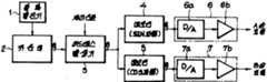
제1도는 모터 제어 회로의 블럭도.1 is a block diagram of a motor control circuit.
제2(a)도 내지 제2(c)도는 각각 어드레스 발생기의 각 블럭의 데이타 내용 도시도.2 (a) to 2 (c) are diagrams showing the data contents of each block of the address generator.
제3(a)도는 워블링(wobbling)시에 있어서의 구동 파형도.3 (a) is a drive waveform diagram when wobbling.
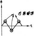
제3(b)도는 워블링시의 회전자(rotor) 회전각의 특성선도.3 (b) is a characteristic diagram of a rotor rotation angle at the time of wobbling.
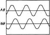
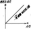
제4(a)도는 선형 이동시의 구동 파형도.4 (a) is a drive waveform diagram during linear movement.
제4(b)도는 선형 이동시의 회전자 회전각의 특성선도.4 (b) is a characteristic line diagram of the rotor rotation angle during linear movement.
제5 도 내지 제6(b)도는 종래예의 도시도.5 to 6 (b) are illustrations of conventional examples.
제5 도는 모터 제어 회로의 블럭도.5 is a block diagram of a motor control circuit.
제6(a)도는 워블링시의 구동 파형도.Fig. 6 (a) is a drive waveform diagram when wobbling.
제6(b)도는 워블링시의 회전자 회전각의 특성선도.Fig. 6 (b) is a characteristic diagram of the rotor rotation angle at the time of wobbling.
* 도면의 주요 부분에 대한 부호의 설명* Explanation of symbols for the main parts of the drawings
3 : 어드레스 발생기 4, 5 : 메모리3:
6, 7 : 드라이브 회로6, 7: drive circuit
[산업상 이용분야][Industrial use]
본 발명은 스텝핑 모터의 회전으로 초점 렌즈를 워블링(요동)시킴으로써 초점을 맞추는 초점 장치에 있어서, 상기 스텝핑 모터의 회전을 제어하는 모터 제어 회로에 관한 것이다.BACKGROUND OF THE INVENTION 1. Field of the Invention The present invention relates to a motor control circuit for controlling the rotation of a stepping motor in a focusing apparatus for focusing by wobbling (focusing) a focus lens by rotation of a stepping motor.
[발명의 개요][Overview of invention]
본 발명은 스텝핑 모터를 마이크로 스텝화하여 회전자(rotor)를 회전시킴으로써 초점렌즈를 구동하는 자동 초점 장치에 있어서, 상기 회전자의 각각의 회전 장치 위치에서의 복수 상의 전류값 데이타를 각각 기억하는 메모리와, 이 메모리가 출력하는 전류값 데이타에 기초하여 각 상으로 통전(通電)하는 드라이브 회로와, 상기 메모리의 전류값 데이타를 판독하는 어드레스 발생기를 가지며, 이 어드레스 발생기가 상기 회전자의 회전방향 전환점에서는 시간축에 대한 회전각 궤적의 경사를 완만하게 하는 어드레스를 발생하도록 구성함으로써, 초점 렌즈의 워블링이 매끄럽게되며 진동이나 음향 잡음을 저감시킬 수 있는 것이다.The present invention provides an autofocus apparatus for driving a focus lens by micro-stepping a stepping motor to rotate a rotor, the memory for storing a plurality of phase current value data at respective rotor positions of the rotor, respectively. And a drive circuit which energizes each phase based on the current value data output from this memory, and an address generator for reading the current value data of the memory, wherein the address generator has a rotation direction switching point of the rotor. In the present invention, the wobbling of the focus lens is smoothed and vibration and acoustic noise can be reduced by generating an address that smoothes the inclination of the rotation angle trajectory with respect to the time axis.
[종래 기술][Prior art]
근래, 비디오 카메라의 자동 초점의 핀트 검출 방식으로서는 비디오 신호의 고역 성분의 피크를 검출하는 "산 오르기 방식(mountain climbing system)"이 주류를 이루고 있다. 이 산 오르기 방식은 초점 렌즈를 약간 워블링시키면서 비디오 신호의 고역성분이 많아지는 쪽으로 초점 렌즈를 이동시키거나, 또는 초점 렌즈를 선형으로 정점 근처까지 이동시킨 후에 워블링시켜서 초점 렌즈를 정점위치로 이동시킨다(특원평 1-157554 호 명세서 참조). 그리고, 이 초점 렌즈의 구동용으로서는 제어의 용이성 때문에 스텝핑 모터가 사용된다.In recent years, the "mountain climbing system" which detects the peak of the high frequency component of a video signal is mainstream as the focus detection method of the autofocus of a video camera. This mountain climbing method moves the focus lens toward the higher frequency component of the video signal while slightly wobbling the focus lens, or by moving the focus lens linearly near the vertex and then wobbling to move the focus lens to the vertex position. (See the specification of Japanese Patent Application No. 1-157554). And for driving this focusing lens, a stepping motor is used for ease of control.
[발명이 해결하고자 하는 과제][Problem to Solve Invention]
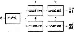
그러나, 스텝핑 모터는 DC 모터 등에 비해 진동이 크므로, 이 진동 저감을 위해, 마이크로 스텝 회로를 적용하는 것이 고려된다. 이 마이크로 스텝 회로는 제5 도에 도시하듯이, 카운터(2)와 이 카운터(2)의 카운트 값을 판독 신호로 하는 SIN 파형 ROM(8) 및 COS 파형 ROM(9)을 가지며, 이 각 ROM(8, 9)의 데이타에 기초하여 A 상과 B 상의 코일로 통전(通電)된다. 초점 렌즈를 한 방향으로 이동시키는 경우에는 제4(a)도에 도시하는 것 같은 구동 전류가 A 상과 B 상에 통전되어서 제4(b)도와 같이 회전자가 회전함으로써 매끄럽고 저진동인 한방향의 회전이 행해진다. 초점 렌즈를 워블링시키는 경우에는, 제6(a)도에 도시하듯이 정역(正逆)의 한 방향의 회전을 조합한 구동 전류가 A 상과 B 상에 통전하는 것이 일반으로 고려되며, 제6(b)도와 같이 회전자가 정역 방향으로 회전한다.However, since the stepping motor has a higher vibration than a DC motor or the like, it is considered to apply a micro step circuit for reducing the vibration. As shown in FIG. 5, this micro step circuit has a counter 2 and a SIN waveform ROM 8 and a
그런데, 제6(b)도에 도시하듯이 시간축에 대한 회전자의 회전방향의 전환은 급격히 행해지므로, 워블링의 전환점에서 큰 진동이 발생하며, 또, 큰 음향 잡음도 발생한다.By the way, as shown in Fig. 6 (b), since the rotational direction of the rotor is changed rapidly with respect to the time axis, large vibration occurs at the switching point of wobbling, and large acoustic noise is also generated.
그래서, 본 발명은 초점 렌즈의 구동용에 스텝핑 모터를 사용한 것에 있어서, 워블링을 매끄럽게 행하고 진동이나 음향 잡음을 저감시킬 수 있는 자동 초점장치의 모터 제어회로를 제공하는 것을 과제로 한다.Accordingly, an object of the present invention is to provide a motor control circuit of an autofocusing device capable of smoothly wobbling and reducing vibration and acoustic noise in using a stepping motor for driving a focus lens.
[과제를 해결하기 위한 수단][Means for solving the problem]
상기 과제를 달성하기 위한 본 발명에 관한 자동 초점 장치의 모터 제어 회로는, 스텝핑 모터를 가지며, 이 스텝핑 모터의 복수 상의 코일에 정현파형의 전류를 통전하여 마이크로 스텝화함으로써 회전자를 회전시키고, 이 회전자의 회전에 따라서 초점 렌즈를 변위시키는 자동 초점 장치에 있어서, 상기 회전자의 각각의 회전 장치 위치에서의 복수 상의 상기 코일로의 각각의 전류값 데이타를 각각 기억하는 메모리와, 이 메모리가 출력하는 전류값 데이타에 기초하여 각 상의 상기 코일에 통전하는 드라이브 회로와, 상기 메모리의 전류값 데이타를 판독하는 어드레스를 발생하는 어드레스 발생기를 가지며, 이 어드레스 발생기가 상기 회전자의 회전 방향 전환점에서는 시간축에 대한 회전각 궤적의 경사를 완만하게 하는 어드레스를 발생하도록 구성한 것이다.The motor control circuit of the autofocus device according to the present invention for achieving the above object has a stepping motor, and rotates the rotor by applying a sine wave current to a plurality of coils of the stepping motor and micro-stepping it. An autofocus device for displacing a focus lens in accordance with rotation of a rotor, the memory comprising: a memory for storing respective current value data to a plurality of phases of coils at respective rotor positions of the rotor, and the memory outputs the memory; A drive circuit for energizing the coils of each phase based on the current value data and an address generator for generating an address for reading the current value data of the memory, the address generator having a time axis at a rotation direction change point of the rotor. Configured to generate an address that smoothes the slope of the rotation angle trajectory for the It is.
[작용][Action]
워블링 모드에서는 어드레스 발생기가 회전자의 회전 방향 전환점에서 회전 각 궤적의 경사를 완만하게 하는 어드레스를 메모리에 송출하고, 메모리에서 이것에 대응하는 전류값 데이타가 판독되어서 모터가 구동되기 때문에, 초점 렌즈는 시간축에 대한 변위가 예컨대 정현파가 되도록 하는 워블링을 행한다.In the wobbling mode, since the address generator sends an address to the memory to smooth the tilt of the rotation angle trajectory at the turning direction of the rotation of the rotor, the current value data corresponding to this is read from the memory and the motor is driven. Performs wobbling such that the displacement with respect to the time axis becomes a sinusoidal wave, for example.
[실시예]EXAMPLE
이하, 본 발명의 실시예를 도면을 사용하여 설명한다.Best Mode for Carrying Out the Invention Embodiments of the present invention will now be described with reference to the drawings.
제1도 내지 제4(b)도에는 본 발명의 한 실시예가 도시되어 있다. 이 실시예의 자동 초점 장치는 스텝핑 모터를 가지며, 이 스텝핑 모터의 구동에 의해 초점 렌즈가 광축방향으로 이동할 수 있도록 구성되어 있다. 스텝핑 모터의 회전자의 회전각도와 초점 렌즈의 이동량은 1 대 1 로 대응하고 있다. 스텝핑 모터는 A 상과 B 상의 2 상의 코일을 가지며, 이 스텝핑 모터의 모터 제어 회로가 제1도에 도시되어 있다.1 through 4 (b) illustrate one embodiment of the present invention. The auto focusing apparatus of this embodiment has a stepping motor, and is configured to be able to move the focus lens in the optical axis direction by driving of the stepping motor. The rotation angle of the rotor of the stepping motor and the amount of movement of the focus lens correspond one to one. The stepping motor has coils of two phases A and B, and the motor control circuit of this stepping motor is shown in FIG.
제1도에 있어서, 클록 발진기(1)의 출력은 카운터(2)에 전달되며, 카운터(2)는 이 클록에 의해서 카운트업 한다. 카운터(2)는 8 비트의 카운트 값(0∼255)을 어드레스 발생기(3)에 출력한다. 어드레스 발생기(3)는 ROM으로 구성되며, 000∼OFF 번지의 A 블록에는 제2(a)도, 100∼1FF 번지의 B 블록에는 제2(b)도, 200∼2FF 번지의 C 블록에는 제2(c)도에 각각 도시하는 특성선의 어드레스 데이타가 수납되어 있다. 아래에 설명하는 바와 같이, 이 각각의 특성선과 마찬가지의 시간축에 대한 회전각 변위(초점 렌즈의 변위)가 얻어지며, 이 어드레스 발생기(3)는 회전자의 회전방향 전환점에서는 시간축에 대한 회전각 궤적의 경사가 완만한 정현파가 되도록 어드레스를 발생한다. 상기 A, B, C 중 어떤 블럭의 어드레스 데이타가 출력될지는 제어 신호에 의해서 선택되며, 이 어드레스 발생기(3)의 어드레스 데이타는 2 개의 메모리(4, 5)에 각각 출력된다. 한쪽의 메모리(4)는 어드레스 데이타의 값이 차례로 카운트업되는 경우(제2(b)도에 도시하는 경우)에는 SIN 파형이 되는 전류값 데이타를, 다른쪽의 메모리(5)는 마찬가지로 카운트업 되는 경우에는 COS 파형으로 되는 전류값 데이타를 각각 갖는다. 이 각 메모리(4, 5)의 출력은 각각의 드라이브 회로(6, 7)에 전달된다. 각 드라이브 회로(6, 7)는 D/A 변환기(6a, 7a)와 증폭기(6b, 7b)를 가지며, 이 각 드라이브 회로(6, 7)의 출력이 A 상 코일 및 B 상 코일에 각각 공급된다.In FIG. 1, the output of the clock oscillator 1 is transmitted to the counter 2, and the counter 2 counts up by this clock. The counter 2 outputs an eight-bit count value (0 to 255) to the address generator 3. The address generator 3 is composed of a ROM. The address generator 3 is composed of a ROM, a second block (a) for an A block at
이하, 상기 구성의 작용에 대해서 설명한다.Hereinafter, the effect | action of the said structure is demonstrated.
초점 렌즈를 선형 이동하는 경우에는 제어신호로서 B 블록이 선택된다. B 블록이 선택되면, 어드레스 발생기(3)가 카운터(2)의 카운트 값에 의해서 제2(b)도에 도시하는 데이타를 각각의 메모리(4, 5)에 출력한다. 그러면, 각각의 메모리(4, 5)는 어드레스 발생기(3)의 데이타를 판독 신호로 하여 이것에 기초하여 전류값 데이타를 출력한다. 이 전류값 데이타에 의해서 제4(a)도에 도시하는 것 같은 구동 전류가 각각의 코일에 통전되며, 제4(b)도에 도시하는 것 같이 회전자가 회전해서 초점 렌즈가 한 방향으로 선형 이동한다.In the case of linearly moving the focus lens, the B block is selected as the control signal. When the B block is selected, the address generator 3 outputs the data shown in Fig. 2 (b) to the
초점 렌즈를 워블링하는 경우에는 제어신호로서 A 블럭이 선택된다. A 블록이선택되면, 어드레스 발생기(3)가 제2(a)도에 도시하는 데이타를 각각의 메모리(4, 5)에 출력하고, 제3(a)도에 도시하는 것 같은 구동 전류가 각각의 코일에 통전되며, 제3(b)도에 도시하듯이 회전자가 회전해서 초점렌즈가 워블링한다. 이 워블링은 시간축에 대해서 정현파형으로 되며 초점렌즈의 반전 이동이 원활히 행해지므로 진동이 작고, 또, 마찬가지로 음향 잡음도 작다.In the case of wobbling the focus lens, the A block is selected as the control signal. When the A block is selected, the address generator 3 outputs the data shown in FIG. 2 (a) to each of the
초점렌즈를 워블링시키면서 이동하는 경우에는 제어 신호로서 C 블럭이 선택된다. C 블럭이 선택되면, 어드레스 발생기(3)가 제2(c)도에 도시하는 데이타를 출력하여 초점렌즈가 워블링하면서 한 방향으로 이동한다. 이때의 워블링도 거의 정현파형이 되므로 저진동이며, 저음향 잡음이 된다.When moving while wobbling the focus lens, the C block is selected as the control signal. When the C block is selected, the address generator 3 outputs the data shown in Fig. 2C and moves in one direction while the focal lens is wobbling. The wobbling at this time is also almost sinusoidal, resulting in low vibration and low acoustic noise.
또한, 이 실시예에 있어서는 제2(a) 내지 (c)도에 도시하는 3 종류의 동작밖에 선택되지 않으나, 그 이외의 각종 동작을 어드레스 발생기(3)의 데이타 내용을 변경 또는 추가함으로써 가능하게 할 수 있다.In this embodiment, only three types of operations shown in Figs. 2 (a) to (c) are selected, but various other operations are possible by changing or adding the data contents of the address generator 3. can do.
[발명의 효과][Effects of the Invention]
상술된 바와 같이 본 발명에 의하면, 스텝핑모터를 마이크로 스텝화하여 회전자를 회전시킴으로써 초점렌즈를 구동하는 자동 초점 장치에 있어서, 상기 회전자의 각각의 회전 정지 위치에서의 복수 상의 전류값 데이타를 각각 기억하는 메모리와, 이 메모리가 출력하는 전류값 데이타에 기초하여 각 상으로 통전하는 드라이브 회로와, 상기 메모리의 전류값 데이타를 판독하는 어드레스 발생기를 가지며, 이 어드레스 발생기가 상기 회전자의 회전방향 전환점에서는 시간측에 대한 회전각 궤적의 경사를 완만하게 하는 어드레스를 발생하도록 구성했으므로, 초점 렌즈의 워블링이 매끄럽게 되며, 진동이나 음향 잡음을 저감할 수 있다는 효과를 달성한다.As described above, according to the present invention, in an autofocus apparatus for driving a focus lens by micro-stepping a stepping motor to rotate a rotor, the plurality of phase current value data at respective rotation stop positions of the rotor are respectively obtained. A memory to be stored, a drive circuit for energizing each phase based on the current value data outputted by the memory, and an address generator for reading the current value data of the memory, wherein the address generator is a rotation direction switching point of the rotor. Has been configured to generate an address that smoothes the inclination of the rotational angle trajectory with respect to the time side, so that the wobbling of the focus lens is smoothed and vibration and acoustic noise can be reduced.
Claims (1)
Translated fromKoreanApplications Claiming Priority (2)
| Application Number | Priority Date | Filing Date | Title |
|---|---|---|---|
| JP2098592AJP3024164B2 (en) | 1990-04-13 | 1990-04-13 | Motor control circuit of autofocus device |
| JP98592 | 1990-04-13 |
Publications (2)
| Publication Number | Publication Date |
|---|---|
| KR910019411A KR910019411A (en) | 1991-11-30 |
| KR100236356B1true KR100236356B1 (en) | 1999-12-15 |
Family
ID=14223913
Family Applications (1)
| Application Number | Title | Priority Date | Filing Date |
|---|---|---|---|
| KR1019910005555AExpired - Fee RelatedKR100236356B1 (en) | 1990-04-13 | 1991-04-08 | Motor control circuit for autofocus unit |
Country Status (5)
| Country | Link |
|---|---|
| US (1) | US5252903A (en) |
| EP (1) | EP0452226B1 (en) |
| JP (1) | JP3024164B2 (en) |
| KR (1) | KR100236356B1 (en) |
| DE (1) | DE69126731T2 (en) |
Families Citing this family (10)
| Publication number | Priority date | Publication date | Assignee | Title |
|---|---|---|---|---|
| JP2798480B2 (en)* | 1990-05-14 | 1998-09-17 | キヤノン株式会社 | Lens drive |
| JPH08275590A (en)* | 1995-03-27 | 1996-10-18 | Sony Corp | Portable video camera |
| JPH1118490A (en)* | 1997-06-27 | 1999-01-22 | Matsushita Electric Ind Co Ltd | Driving device for stepping motor |
| DE19730391C1 (en)* | 1997-07-16 | 1999-01-28 | Zentr Mikroelekt Dresden Gmbh | Method and circuit arrangement for controlling a stepper motor |
| US6121745A (en)* | 1997-10-02 | 2000-09-19 | Warner Electric Technology, Inc. | Direct current command generation for a stepper motor drive |
| US5914579A (en)* | 1997-10-02 | 1999-06-22 | Dana Corporation | Direct current command generation for a stepper motor drive |
| DE19927129C1 (en) | 1999-06-15 | 2001-01-04 | Wolf Gmbh Richard | Focusing and focal width adjuster for video camera with zoom lens produces time window which is supplied to focusing circuit and zoom control circuit to provide vertical scanning gap of video signal |
| US8362409B2 (en)* | 2009-10-29 | 2013-01-29 | Applied Precision, Inc. | System and method for continuous, asynchronous autofocus of optical instruments |
| JP5963526B2 (en)* | 2012-04-27 | 2016-08-03 | キヤノン株式会社 | Lens apparatus and imaging apparatus having the same |
| CN107635870A (en)* | 2016-10-27 | 2018-01-26 | 深圳市大疆创新科技有限公司 | Steering wheel and its control method, unmanned plane |
Family Cites Families (7)
| Publication number | Priority date | Publication date | Assignee | Title |
|---|---|---|---|---|
| US4087732A (en)* | 1976-05-21 | 1978-05-02 | Pritchard Eric K | Digital stepping motor device circuit |
| US4429968A (en)* | 1981-07-22 | 1984-02-07 | Canon Kabushiki Kaisha | Automatic focus control device |
| KR930008570B1 (en)* | 1984-03-31 | 1993-09-09 | 쏘니 가부시기가이샤 | Head shifter |
| US4634949A (en)* | 1985-03-07 | 1987-01-06 | Tektronix, Inc. | Control devices for use with a stepping motor |
| US4652806A (en)* | 1986-01-23 | 1987-03-24 | Aerotech, Inc. | Micro-stepping translator controller |
| KR910009562B1 (en)* | 1987-02-06 | 1991-11-21 | 가부시기가이샤 히다찌세이사꾸쇼 | Auto focusing devices such as video cameras |
| US4920420A (en)* | 1988-11-10 | 1990-04-24 | Hitachi, Ltd. | Automatic focusing system |
- 1990
- 1990-04-13JPJP2098592Apatent/JP3024164B2/ennot_activeExpired - Fee Related
- 1991
- 1991-04-08USUS07/681,733patent/US5252903A/ennot_activeExpired - Lifetime
- 1991-04-08KRKR1019910005555Apatent/KR100236356B1/ennot_activeExpired - Fee Related
- 1991-04-12DEDE69126731Tpatent/DE69126731T2/ennot_activeExpired - Fee Related
- 1991-04-12EPEP91400984Apatent/EP0452226B1/ennot_activeExpired - Lifetime
Also Published As
| Publication number | Publication date |
|---|---|
| JP3024164B2 (en) | 2000-03-21 |
| EP0452226A3 (en) | 1992-10-28 |
| DE69126731D1 (en) | 1997-08-14 |
| EP0452226A2 (en) | 1991-10-16 |
| DE69126731T2 (en) | 1997-10-23 |
| KR910019411A (en) | 1991-11-30 |
| US5252903A (en) | 1993-10-12 |
| EP0452226B1 (en) | 1997-07-09 |
| JPH04299A (en) | 1992-01-06 |
Similar Documents
| Publication | Publication Date | Title |
|---|---|---|
| KR100426552B1 (en) | Portable video camera | |
| KR100236356B1 (en) | Motor control circuit for autofocus unit | |
| US5298933A (en) | Image pickup apparatus | |
| US20100097020A1 (en) | Drive apparatus | |
| JP2729009B2 (en) | Video camera | |
| US8588601B2 (en) | Drive control apparatus, image pickup apparatus, and drive control method which perform micro step drive of stepping motor | |
| US6967686B1 (en) | Image sensing method, image sensing apparatus, lens control method therefor, and storage medium | |
| JP4072220B2 (en) | Focus operation device | |
| JPH0777648A (en) | Lens control device | |
| JPH06201975A (en) | Lens driving controller | |
| JPH1141989A (en) | Drive gear for stepping motor and monitor camera system using it | |
| JP6679218B2 (en) | Optical equipment and actuator processing program | |
| JP6168841B2 (en) | DRIVE CONTROL DEVICE, IMAGING DEVICE, DRIVE CONTROL METHOD, PROGRAM, AND STORAGE MEDIUM | |
| JP3513167B2 (en) | Lens control device | |
| JPH0618760A (en) | Driving system for camera lens | |
| JPS62180338A (en) | Focus adjusting device | |
| JPS6387871A (en) | automatic focus device | |
| JP2997475B2 (en) | camera | |
| JPH1118461A (en) | Control device of vibration type driving device and device provided with the same | |
| JPH0545566A (en) | Camera lens drive controller | |
| JP3782522B2 (en) | Pulse motor drive control method and apparatus | |
| JP6508937B2 (en) | Stepping motor control device, interchangeable lens, stepping motor control method, program and storage medium | |
| JP4072224B2 (en) | Lens control apparatus, method, and computer-readable recording medium | |
| JP2001069793A (en) | Driving device using stepping motor, device having the same, light amount adjusting device, and optical device | |
| JPS62284318A (en) | Focusing device |
Legal Events
| Date | Code | Title | Description |
|---|---|---|---|
| PA0109 | Patent application | St.27 status event code:A-0-1-A10-A12-nap-PA0109 | |
| R17-X000 | Change to representative recorded | St.27 status event code:A-3-3-R10-R17-oth-X000 | |
| PG1501 | Laying open of application | St.27 status event code:A-1-1-Q10-Q12-nap-PG1501 | |
| A201 | Request for examination | ||
| PA0201 | Request for examination | St.27 status event code:A-1-2-D10-D11-exm-PA0201 | |
| E902 | Notification of reason for refusal | ||
| PE0902 | Notice of grounds for rejection | St.27 status event code:A-1-2-D10-D21-exm-PE0902 | |
| T11-X000 | Administrative time limit extension requested | St.27 status event code:U-3-3-T10-T11-oth-X000 | |
| R17-X000 | Change to representative recorded | St.27 status event code:A-3-3-R10-R17-oth-X000 | |
| T11-X000 | Administrative time limit extension requested | St.27 status event code:U-3-3-T10-T11-oth-X000 | |
| T11-X000 | Administrative time limit extension requested | St.27 status event code:U-3-3-T10-T11-oth-X000 | |
| P11-X000 | Amendment of application requested | St.27 status event code:A-2-2-P10-P11-nap-X000 | |
| P13-X000 | Application amended | St.27 status event code:A-2-2-P10-P13-nap-X000 | |
| E701 | Decision to grant or registration of patent right | ||
| PE0701 | Decision of registration | St.27 status event code:A-1-2-D10-D22-exm-PE0701 | |
| GRNT | Written decision to grant | ||
| PR0701 | Registration of establishment | St.27 status event code:A-2-4-F10-F11-exm-PR0701 | |
| PR1002 | Payment of registration fee | St.27 status event code:A-2-2-U10-U11-oth-PR1002 Fee payment year number:1 | |
| PG1601 | Publication of registration | St.27 status event code:A-4-4-Q10-Q13-nap-PG1601 | |
| PR1001 | Payment of annual fee | St.27 status event code:A-4-4-U10-U11-oth-PR1001 Fee payment year number:4 | |
| PR1001 | Payment of annual fee | St.27 status event code:A-4-4-U10-U11-oth-PR1001 Fee payment year number:5 | |
| PR1001 | Payment of annual fee | St.27 status event code:A-4-4-U10-U11-oth-PR1001 Fee payment year number:6 | |
| PR1001 | Payment of annual fee | St.27 status event code:A-4-4-U10-U11-oth-PR1001 Fee payment year number:7 | |
| PR1001 | Payment of annual fee | St.27 status event code:A-4-4-U10-U11-oth-PR1001 Fee payment year number:8 | |
| R18-X000 | Changes to party contact information recorded | St.27 status event code:A-5-5-R10-R18-oth-X000 | |
| PR1001 | Payment of annual fee | St.27 status event code:A-4-4-U10-U11-oth-PR1001 Fee payment year number:9 | |
| FPAY | Annual fee payment | Payment date:20080813 Year of fee payment:10 | |
| PR1001 | Payment of annual fee | St.27 status event code:A-4-4-U10-U11-oth-PR1001 Fee payment year number:10 | |
| LAPS | Lapse due to unpaid annual fee | ||
| PC1903 | Unpaid annual fee | St.27 status event code:A-4-4-U10-U13-oth-PC1903 Not in force date:20091001 Payment event data comment text:Termination Category : DEFAULT_OF_REGISTRATION_FEE | |
| PN2301 | Change of applicant | St.27 status event code:A-5-5-R10-R13-asn-PN2301 St.27 status event code:A-5-5-R10-R11-asn-PN2301 | |
| PC1903 | Unpaid annual fee | St.27 status event code:N-4-6-H10-H13-oth-PC1903 Ip right cessation event data comment text:Termination Category : DEFAULT_OF_REGISTRATION_FEE Not in force date:20091001 | |
| P22-X000 | Classification modified | St.27 status event code:A-4-4-P10-P22-nap-X000 | |
| PN2301 | Change of applicant | St.27 status event code:A-5-5-R10-R13-asn-PN2301 St.27 status event code:A-5-5-R10-R11-asn-PN2301 | |
| P22-X000 | Classification modified | St.27 status event code:A-4-4-P10-P22-nap-X000 |