KR100236350B1 - Method for displaying working state of airconditioner - Google Patents
Method for displaying working state of airconditionerDownload PDFInfo
- Publication number
- KR100236350B1 KR100236350B1KR1019970028181AKR19970028181AKR100236350B1KR 100236350 B1KR100236350 B1KR 100236350B1KR 1019970028181 AKR1019970028181 AKR 1019970028181AKR 19970028181 AKR19970028181 AKR 19970028181AKR 100236350 B1KR100236350 B1KR 100236350B1
- Authority
- KR
- South Korea
- Prior art keywords
- air conditioner
- key
- led module
- temperature
- user
- Prior art date
- Legal status (The legal status is an assumption and is not a legal conclusion. Google has not performed a legal analysis and makes no representation as to the accuracy of the status listed.)
- Expired - Fee Related
Links
Images


Classifications
- F—MECHANICAL ENGINEERING; LIGHTING; HEATING; WEAPONS; BLASTING
- F24—HEATING; RANGES; VENTILATING
- F24F—AIR-CONDITIONING; AIR-HUMIDIFICATION; VENTILATION; USE OF AIR CURRENTS FOR SCREENING
- F24F11/00—Control or safety arrangements
- F24F11/50—Control or safety arrangements characterised by user interfaces or communication
- F24F11/52—Indication arrangements, e.g. displays
- F24F11/523—Indication arrangements, e.g. displays for displaying temperature data
- F—MECHANICAL ENGINEERING; LIGHTING; HEATING; WEAPONS; BLASTING
- F24—HEATING; RANGES; VENTILATING
- F24F—AIR-CONDITIONING; AIR-HUMIDIFICATION; VENTILATION; USE OF AIR CURRENTS FOR SCREENING
- F24F2110/00—Control inputs relating to air properties
- F24F2110/10—Temperature
Landscapes
- Engineering & Computer Science (AREA)
- Human Computer Interaction (AREA)
- Chemical & Material Sciences (AREA)
- Combustion & Propulsion (AREA)
- Mechanical Engineering (AREA)
- General Engineering & Computer Science (AREA)
- Air Conditioning Control Device (AREA)
Abstract
Translated fromKoreanDescription
Translated fromKorean본 발명은 공기조화기에 관한 것으로서, 특히 공기조화기의 동작상태 표시방법에 관한 것이다.The present invention relates to an air conditioner, and more particularly, to a method for displaying an operating state of an air conditioner.
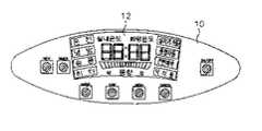
종래의 기술에 따른 공기조화기의 표시장치는 도 1a에 도시된 바와 같이 사<용자가 공기조화기를 동작시키거나 동작 관련사항을 설정하기 위한 각종 키(Key)를 구비한 키신호입력부(10), 공기조화기의 동작상태를 표시하기 위한 LED모듈(Light Emitting Diode Module)(12), 상기 키신호입력부(10)를 통해 입력된 신호에 따라 상기 LED 모듈(12)을 제어하는 제어부(11)로 구성된다.The display device of the air conditioner according to the related art is a key
그리고 도 1b는 표시장치의 외관을 나타낸 평면도로서 도 1b에 도시된 바와 같이, 키신호입력부(10)와 LED 모듈(12)이 별도의 공간을 점유하고 설치된다.FIG. 1B is a plan view illustrating the appearance of a display device, and as shown in FIG. 1B, the key
이와 같이 구성된 종래의 공기조화기의 표시장치의 동작을 도 1b를 참조하여 설명한다.The operation of the display device of the conventional air conditioner configured as described above will be described with reference to FIG. 1B.
예를 들어, 공기조화기의 운전이 정지된 상태에서, 사용자가 공기조화기를 동작시키기 위하여 키신호입력부(10)의 '온/오프' 키를 누르면, 제어부(11)는 이를 공기조화기 운전명령으로 인식함과 동시에 사용자에게 알릴 수 있도록 LED 모듈(12)에 제어신호를 인가한다. 이어서 LED 모듈(12)은 제어부(11)의 제어신호에 따라 '운전'에 상응하는 LED, 예를 들어 청색 LED를 구동시킨다. 그리고 청색 LED는 사용자가 공기조화기의 운전을 정지시키기 위하여 '온/오프' 키를 다시 누를 때 까지 계속 켜진상태를 유지한다.For example, when the user of the air conditioner is stopped, when the user presses the 'on / off' key of the key
한편, 사용자가 키신호입력부(10)의 'HEAT'키를 누르면 제어부(11)는 그에 따라 LED 모듈(12)에 제어신호를 인가한다. 이어서 LED 모듈(12)은 '히터'에 상응하는 LED를 약 3초동안 '온' 시킨다. 그리고 사용자가 그 이외의 키 즉, 'MODE', 'SPEED' 등을 누를 경우에도 LED 모듈(12)의 해당 LED가 각각의 설정시간동안 켜진다.Meanwhile, when the user presses the 'HEAT' key of the key
상술한 바와 같이, 사용자가 각종 키를 눌렀을 때, '온/오프'키의 경우 공기조화기가 운전되는 동안 LED 모듈(12)의 해당 LED가 계속 켜져있고 이를 제외한 키들은 LED 모듈(12)의 해당 LED가 각각의 설정시간동안 켜졌다가 꺼짐으로써 사용자가 입력한 키신호를 인식하였음을 표시한다.As described above, when the user presses various keys, the corresponding LED of the
종래의 기술에 따른 공기조화기는 다음과 같은 문제점이 있다.The air conditioner according to the prior art has the following problems.
첫째, 기계적인 접점에 의한 키를 사용하므로 장시간 사용시 접촉불량이 발생하여 시스템이 오동작할 수 있다.First, since the key by the mechanical contact is used, the system may malfunction due to bad contact when used for a long time.
둘째, 키신호입력부와 LED 모듈의 설치공간이 별도로 필요하므로 디스플레이부의 전체면적을 일정범위 이내로 감소시킬 수 없다.Second, since the installation space of the key signal input unit and the LED module is required separately, the total area of the display unit cannot be reduced within a certain range.
셋째, 공기조화기의 각종 동작상태를 동작조건 즉, 실내온도의 변화 또는 키신호의 입력여부 등에 상관없이 단일 색상으로 LED 모듈에 디스플레이 하여 사용자의 인식능력을 저하시키므로 각종 동작상태 파악이 용이하지 못하다.Third, it is not easy to grasp various operating states because it displays a single color on the LED module regardless of the operating conditions, that is, the change of room temperature or input of key signal, so as to reduce the user's recognition ability. .
따라서 본 발명은 이러한 종래의 문제점을 해결하기 위하여 안출한 것으로서 공기조화기의 동작상태를 용이하게 파악할 수 있도록 한 공기조화기의 동작상태 표시방법을 제공함에 그 목적이 있다.Accordingly, an object of the present invention is to provide a method for displaying an operating state of an air conditioner, which is designed to solve such a conventional problem, so that the operating state of the air conditioner can be easily grasped.
도 1a 내지 1b는 종래의 기술에 따른 공기조화기의 표시장치를 나타낸 도면,1a to 1b is a view showing a display device of an air conditioner according to the prior art,
도 2a 내지 2c는 본 발명에 따른 공기조화기의 표시장치를 나타낸 도면,2a to 2c are views illustrating a display device of an air conditioner according to the present invention;
도 3은 본 발명에 따른 공기조화기의 키신호 입력을 표시하는 방법을 나타낸 플로우챠트이고,3 is a flowchart showing a method for displaying a key signal input of an air conditioner according to the present invention;
도 4는 본 발명에 따른 공기조화기의 실내온도와 희망온도의 변화를 표시하는 방법을 나타낸 플로우챠트이다.Figure 4 is a flow chart showing a method for displaying a change in the room temperature and the desired temperature of the air conditioner according to the present invention.
도면의 주요 부분에 대한 부호의 설명Explanation of symbols for the main parts of the drawings
10: 키신호 입력부11, 31: 제어부10: key signal input unit 11, 31: control unit
12, 32: LED 모듈30: 터치 패널12, 32: LED module 30: touch panel
본 발명은 제어부, LED 모듈 및 LED 모듈 상측에 터치패널을 구비한 공기조화기의 동작상태 표시방법에 있어서, 동작전원을 인가받고 LED 모듈중 해당 LED를 구동하여 현재 공기조화기의 동작상태를 표시하는 단계와, 사용자가 키입력부를 통<해 소정 키신호를 입력하면 해당 키가 온도 설정키인지 여부를 판단하는 단계와, 그 판단결과 온도 설정키이면 사용자가 설정한 온도와 현재 실내온도를 비교하는 단계와, 그 비교결과 사용자 설정온도가 현재 실내온도에 비해 높을 경우와 낮을 경우 및 같은 경우 각각에 대해 LED 모듈의 색상을 다르게 표시하는 단계를 포함하여 이루어짐을 특징으로 한다.The present invention provides a control unit, LED module and the operation state display method of the air conditioner having a touch panel on the upper side of the LED module, the operating power is applied to display the operation state of the current air conditioner by driving the corresponding LED of the LED module Determining whether the corresponding key is a temperature setting key when the user inputs a predetermined key signal through the key input unit; and if the temperature setting key indicates that the user sets the current indoor temperature, And comparing the color of the LED module with respect to the case where the user setting temperature is higher and lower than the current room temperature and the same as the comparison result.
이하, 첨부된 도면을 참조하여 본 발명에 따른 공기조화기의 동작상태 표시장치를 설명한다.Hereinafter, an operation state display apparatus of an air conditioner according to the present invention will be described with reference to the accompanying drawings.
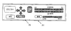
도 2a는 본 발명에 따른 공기조화기의 표시장치의 구성을 나타낸 블록도, 도 2b는 본 발명에 따른 공기조화기의 표시장치의 외관을 나타낸 평면도이고, 도 2c는 본 발명에 따른 공기조화기의 표시장치중 터치 패널과 LED 모듈의 설치상태를 나타낸 측단면도이다.Figure 2a is a block diagram showing the configuration of a display device of the air conditioner according to the present invention, Figure 2b is a plan view showing the appearance of the display device of the air conditioner according to the present invention, Figure 2c is an air conditioner according to the present invention Is a side sectional view showing an installation state of a touch panel and an LED module among display devices.
본 발명에 따른 공기조화기의 표시장치는 도 2a에 도시된 바와 같이, 두가지 색 이상의 빛을 발하는 복수개의 LED가 선택적으로 구동되어 공기조화기의 동작상태 및 동작관련사항을 표시하는 LED 모듈(32), 상기 LED 모듈(32)에 표시된 공기조화기의 동작상태 및 동작관련사항을 사용자가 확인하고 동시에 선택입력할 수 있도록 LED 모듈(32) 상측에 설치된 터치 패널(30), 상기 터치 패널(30)을 통해 선택된 공기조화기의 동작상태 및 동작관련사항에 상응하는 LED가 구동될 수 있도록 상기 LED 모듈(32)을 제어하는 제어부(31)로 구성된다. 이때 터치 패널(30)은 압력센서(도시 생략)를 이용하여 일정부위에 일정레벨 이상의 압력이 가해지면 그에 상응하는 신호를 출력하는 장치이다. 또한 LED 모듈(32)은 '운전', '히터', '<실내온도' 등을 표시하기 위한 각각의 부위에 서로 다른 두가지색 이상의 LED를 구비한다.As shown in FIG. 2A, a display device of an air conditioner according to the present invention includes a plurality of LEDs emitting two or more colors of LEDs to selectively drive the
그리고 도 2b에 도시된 바와 같이, LED 모듈(32)과 터치 패널(30)이 동일한 공간을 점유하고 설치되며 그 상세한 설치구조는 도 2c에 도시된다. 즉, 사용자가 LED 모듈(32)에 표시된 동작상태를 확인하고 그 해당부위에 일정레벨 이상의 압력을 가하여 동작관련 신호를 입력할 수 있도록 상기 LED 모듈(32) 상측에 겹친 형태로 설치된다.As shown in FIG. 2B, the
이와 같이 구성된 공기조화기의 표시장치는 사용자가 LED 모듈(32)에 표시된 사항중 하나를 선택하기 위하여 일정 키신호를 입력하면 즉, 상기 LED 모듈(32)상부에 있는 터치 패널(30)의 해당부위에 일정레벨 이상의 압력을 가하면, 상기 터치 패널(30)은 그에 따른 신호를 출력한다. 이어서 제어부(31)가 터치 패널(30)에서 출력된 신호에 따라 사용자가 입력한 키신호가 어떤 명령인지 파악하고 그에 따른 제어신호를 LED 모듈(32)에 인가한다. 그리고 LED 모듈(32)은 상기 제어부(31)의 제어신호에 상응하는 일정색의 LED를 구동시켜, 사용자의 명령을 인식하였음을 알린다.In the display device of the air conditioner configured as described above, when a user inputs a predetermined key signal to select one of the items displayed on the
이하, 본 발명에 따른 공기조화기의 동작상태 표시방법을 첨부한 도면을 참조하여 설명하면 다음과 같다.Hereinafter, an operation state display method of an air conditioner according to the present invention will be described with reference to the accompanying drawings.
도 3은 본 발명에 따른 공기조화기의 키신호입력에 따른 LED 모듈의 표시방법을 나타낸 플로우챠트이고, 도 4는 본 발명에 따른 공기조화기의 실내온도와 희망온도의 변화에 따른 LED 모듈의 표시방법을 나타낸 플로우챠트이다.Figure 3 is a flow chart showing a display method of the LED module according to the key signal input of the air conditioner according to the present invention, Figure 4 is a LED module according to the change in the room temperature and the desired temperature of the air conditioner according to the present invention A flowchart showing the display method.
먼저, 도 3에 도시된 바와 같이, 키신호입력에 따른 LED 모듈의 표시방법은 다음과 같다.First, as shown in Figure 3, the display method of the LED module according to the key signal input is as follows.
먼저, 제어부(31)는 키신호가 입력되는지 여부를 판단한다(S11). 그리고 그 판단결과 키신호가 입력되었으면, 기억장치(도시 생략)의 키 온 비트(Key On Bit)가 '하이' 인지 판단하여(S12), 키 온 비트가 '하이'이면 키 온 비트를 '로우'로 바꾸고(S13), 입력된 키에 상응하는 LED 모듈(32)의 색상을 'A'색으로 변경시키며(S14), 입력된 키에 상응하는 동작명령을 '오프'시킨다(S15). 이때 키 온 비트는 입력된 키에 상응하는 동작의 수행여부를 표시하기 위한 단위 비트로, 동작을 수행중이면 '하이'로, 동작이 수행되지 않으면 '로우'로 상기 기억장치에 기억된다.First, the
한편, 키 온 비트(Key On Bit)가 '하이' 인지 판단하여(S12), 키 온 비트가 '로우'이면 키 온 비트를 '하이'로 바꾸고(S16), 입력된 키에 상응하는 LED 모듈(32)의 색상을 'B'색으로 변경시키며(S17), 입력된 키에 상응하는 동작명령을 '온'시킨다(S18).Meanwhile, it is determined whether the key on bit is 'high' (S12), and when the key on bit is 'low', the key on bit is changed to 'high' (S16), and the LED module corresponding to the input key The color of (32) is changed to the 'B' color (S17), and the operation command corresponding to the input key is 'on' (S18).
예를 들어, 상기 키 온 비트가 '로우'일 경우 그에 상응하는 LED 모듈(32)이 청색(Blue)으로, 키 온 비트가 '하이'일 경우 그에 상응하는 LED 모듈(32)이 적색(Red)으로 설정되고 공기조화기의 동작이 정지된 상태 즉, 키 온 비트가 '로우'이며 그에 상응하는 청색 LED의 구동에 의해 LED 모듈(32)의 '운전/정지' 부분이 청색빛을 발하고 있는 상태에서 사용자가 LED 모듈(32)에 있는 '운전/정지'키에 해당하는 터치 패널(30)의 일정부위에 압력을 가하면, 제어부(31)는 먼저, 키 온 <비트가 '로우' 상태이므로 키 온 비트를 '하이'로 바꾼다. 이어서 LED 모듈(32)의 '운전/정지' 부분에 상응하는 LED중 상기 청색 LED를 '오프'시키고 적색 LED를 구동시켜 '운전/정지' 부분이 적색빛을 발하게 한다.For example, when the key on bit is 'low', the corresponding
그리고 그 이외의 키 즉, '예약', '풍량'키 등을 입력할 경우에도 '운전/정지'키를 입력할 때와 마찬가지로 설정된 각각의 알고리즘에 따라 LED 모듈(32)의 색상을 변경시켜 키신호 입력을 인식하였음을 사용자에게 알린다.In addition, when other keys, ie, 'reservation' and 'wind volume' keys are input, the color of the
또한, 도 4에 도시된 바와 같이, 희망온도와 실내온도의 변화에 따른 LED 모듈(32)의 표시방법은 다음과 같다.In addition, as shown in Figure 4, the display method of the
먼저, 제어부(31)는 공기조화기가 운전중인지 여부를 판단하여(S21), 현제 공기조화기가 운전중이면 실내온도와 사용자가 설정한 희망온도를 비교한다(S22). 이어서 그 비교결과에 따라 즉, 실내온도와 희망온도가 같은 경우, 실내온도가 희망온도보다 높은 경우 그리고 실내온도가 희망온도보다 낮은 경우에 따라 LED 모듈(32)의 색상을 각각 'A', 'B', 'C'로 변경시킨다.First, the
예를 들어, LED 모듈(32)의 온도표시 부분의 색상이 실내온도와 희망온도가 같을 때는 청색으로, 실내온도가 희망온도보다 높을 때는 적색으로, 그리고 실내온도가 희망온도보다 낮을 때는 황색으로 설정되고 공기조화기가 냉방운전을 수행하여 실내온도와 희망온도를 비교한 결과 실내온도와 희망온도가 같으면 LED 모듈(32)의 온도표시 부분은 청색을 유지한다. 이어서 실내온도가 사용자가 설정한 희망온도와 같아졌으므로 공기조화기의 냉방운전이 정지된다. 따라서 일정시간 후 다시 실내온도와 희망온도를 비교한 결과 실내온도가 희망온도보다 높아졌으면 <제어부(31)는 LED 모듈(32)에 제어신호를 인가하여 청색 LED를 '오프'시키고 적색 LED를 '온'시켜 LED 모듈(32)의 색상을 청색에서 적색으로 변경시킨다. 마찬가지로 실내온도가 희망온도까지 낮아질 수 있도록 공기조화기를 냉방운전시키고 일정시간후 실내온도와 희망온도를 비교하여 실내온도가 희망온도보다 낮아졌으면 LED 모듈(32)의 색상을 적색에서 황색으로 변경시킨다.For example, the color of the temperature display of the
상술한 바와 같이 사용자는 LED 모듈(32)에서 온도표시 부분의 색상변화를 보고 현제 실내온도와 희망온도를 비교 판단할 수 있다.As described above, the user may compare the current room temperature with the desired temperature by looking at the color change of the temperature display part in the
본 발명에 따른 공기조화기의 동작상태 표시방법은 다음과 같은 동작상태 및 동작관련사항을 각종 문자, 기호는 물론이고 색상의 변화로써 표시하므로 사용자가 공기조화기의 동작상태 및 관련사항을 일목요연하게 파악할 수 있는 효과가 있다.The operation state display method of the air conditioner according to the present invention displays the following operation state and operation-related matters, as well as various characters, symbols, changes in color, so that the user can clearly see the operation state and related matters of the air conditioner. There is an effect that can be grasped.
Claims (2)
Translated fromKoreanPriority Applications (1)
| Application Number | Priority Date | Filing Date | Title |
|---|---|---|---|
| KR1019970028181AKR100236350B1 (en) | 1997-06-27 | 1997-06-27 | Method for displaying working state of airconditioner |
Applications Claiming Priority (1)
| Application Number | Priority Date | Filing Date | Title |
|---|---|---|---|
| KR1019970028181AKR100236350B1 (en) | 1997-06-27 | 1997-06-27 | Method for displaying working state of airconditioner |
Publications (2)
| Publication Number | Publication Date |
|---|---|
| KR19990004167A KR19990004167A (en) | 1999-01-15 |
| KR100236350B1true KR100236350B1 (en) | 2000-01-15 |
Family
ID=19511719
Family Applications (1)
| Application Number | Title | Priority Date | Filing Date |
|---|---|---|---|
| KR1019970028181AExpired - Fee RelatedKR100236350B1 (en) | 1997-06-27 | 1997-06-27 | Method for displaying working state of airconditioner |
Country Status (1)
| Country | Link |
|---|---|
| KR (1) | KR100236350B1 (en) |
Families Citing this family (1)
| Publication number | Priority date | Publication date | Assignee | Title |
|---|---|---|---|---|
| KR100942549B1 (en)* | 2008-02-29 | 2010-02-16 | 엘지전자 주식회사 | Air conditioner and control method |
- 1997
- 1997-06-27KRKR1019970028181Apatent/KR100236350B1/ennot_activeExpired - Fee Related
Also Published As
| Publication number | Publication date |
|---|---|
| KR19990004167A (en) | 1999-01-15 |
Similar Documents
| Publication | Publication Date | Title |
|---|---|---|
| US8237652B2 (en) | Liquid crystal display apparatus and control method thereof | |
| KR860001323A (en) | Air conditioner | |
| US7106168B2 (en) | Menu driven wall console with LED indicators for garage door operator | |
| RU2006140252A (en) | LIGHTING SYSTEM | |
| CN102023709B (en) | Keyboard and notebook computer | |
| KR100236350B1 (en) | Method for displaying working state of airconditioner | |
| CN104990217A (en) | Operation control method and device of air conditioner and air conditioner | |
| KR102358203B1 (en) | LED driving apparatus and method | |
| CN102877736A (en) | Control mode switching device of automatic door and automatic door utilizing the same | |
| KR101519981B1 (en) | Apparatus and method for controlling lighting switch | |
| US11540368B1 (en) | Color temperature and brightness control system for LED lamp | |
| KR100450300B1 (en) | provision refrigeration plant fan switchboard panel for ship | |
| KR20170048884A (en) | Apparatus for power save controlling of showcase and method thereof | |
| KR100191512B1 (en) | Device of indicating letters with equipment for airconditioner | |
| KR100878134B1 (en) | Electronic control valve system with status display function and control method thereof | |
| KR102193202B1 (en) | Control system for led operation apparatus | |
| KR100489960B1 (en) | Apparatus and method for switching heating by using remote controller | |
| JP2006162125A (en) | Air conditioner display device | |
| KR100520952B1 (en) | Display control device for refrigerator | |
| EP3624562B1 (en) | System for changing a control interface of a controlled device based on functions of the device | |
| JP7374559B2 (en) | Air conditioning control device | |
| KR20010105683A (en) | Method for changing led color of airconditioner | |
| KR19990004174A (en) | Display device and method of air conditioner | |
| KR200262952Y1 (en) | Device for controlling a temperature and humidity | |
| KR100347045B1 (en) | A driving control method for airconditioner |
Legal Events
| Date | Code | Title | Description |
|---|---|---|---|
| A201 | Request for examination | ||
| PA0109 | Patent application | St.27 status event code:A-0-1-A10-A12-nap-PA0109 | |
| PA0201 | Request for examination | St.27 status event code:A-1-2-D10-D11-exm-PA0201 | |
| R17-X000 | Change to representative recorded | St.27 status event code:A-3-3-R10-R17-oth-X000 | |
| PG1501 | Laying open of application | St.27 status event code:A-1-1-Q10-Q12-nap-PG1501 | |
| PN2301 | Change of applicant | St.27 status event code:A-3-3-R10-R13-asn-PN2301 St.27 status event code:A-3-3-R10-R11-asn-PN2301 | |
| E902 | Notification of reason for refusal | ||
| PE0902 | Notice of grounds for rejection | St.27 status event code:A-1-2-D10-D21-exm-PE0902 | |
| T11-X000 | Administrative time limit extension requested | St.27 status event code:U-3-3-T10-T11-oth-X000 | |
| P11-X000 | Amendment of application requested | St.27 status event code:A-2-2-P10-P11-nap-X000 | |
| P13-X000 | Application amended | St.27 status event code:A-2-2-P10-P13-nap-X000 | |
| E701 | Decision to grant or registration of patent right | ||
| PE0701 | Decision of registration | St.27 status event code:A-1-2-D10-D22-exm-PE0701 | |
| GRNT | Written decision to grant | ||
| PR0701 | Registration of establishment | St.27 status event code:A-2-4-F10-F11-exm-PR0701 | |
| PR1002 | Payment of registration fee | St.27 status event code:A-2-2-U10-U11-oth-PR1002 Fee payment year number:1 | |
| PG1601 | Publication of registration | St.27 status event code:A-4-4-Q10-Q13-nap-PG1601 | |
| PN2301 | Change of applicant | St.27 status event code:A-5-5-R10-R13-asn-PN2301 St.27 status event code:A-5-5-R10-R11-asn-PN2301 | |
| PN2301 | Change of applicant | St.27 status event code:A-5-5-R10-R13-asn-PN2301 St.27 status event code:A-5-5-R10-R11-asn-PN2301 | |
| LAPS | Lapse due to unpaid annual fee | ||
| PC1903 | Unpaid annual fee | St.27 status event code:A-4-4-U10-U13-oth-PC1903 Not in force date:20021001 Payment event data comment text:Termination Category : DEFAULT_OF_REGISTRATION_FEE | |
| PN2301 | Change of applicant | St.27 status event code:A-5-5-R10-R13-asn-PN2301 St.27 status event code:A-5-5-R10-R11-asn-PN2301 | |
| PC1903 | Unpaid annual fee | St.27 status event code:N-4-6-H10-H13-oth-PC1903 Ip right cessation event data comment text:Termination Category : DEFAULT_OF_REGISTRATION_FEE Not in force date:20021001 | |
| P22-X000 | Classification modified | St.27 status event code:A-4-4-P10-P22-nap-X000 | |
| P22-X000 | Classification modified | St.27 status event code:A-4-4-P10-P22-nap-X000 | |
| P22-X000 | Classification modified | St.27 status event code:A-4-4-P10-P22-nap-X000 |