KR100234663B1 - Apparatus for limiting working area of an industrial robot - Google Patents
Apparatus for limiting working area of an industrial robotDownload PDFInfo
- Publication number
- KR100234663B1 KR100234663B1KR1019970047121AKR19970047121AKR100234663B1KR 100234663 B1KR100234663 B1KR 100234663B1KR 1019970047121 AKR1019970047121 AKR 1019970047121AKR 19970047121 AKR19970047121 AKR 19970047121AKR 100234663 B1KR100234663 B1KR 100234663B1
- Authority
- KR
- South Korea
- Prior art keywords
- fixed base
- work area
- stopper
- brackets
- stop lever
- Prior art date
- Legal status (The legal status is an assumption and is not a legal conclusion. Google has not performed a legal analysis and makes no representation as to the accuracy of the status listed.)
- Expired - Lifetime
Links
Images


Classifications
- B—PERFORMING OPERATIONS; TRANSPORTING
- B25—HAND TOOLS; PORTABLE POWER-DRIVEN TOOLS; MANIPULATORS
- B25J—MANIPULATORS; CHAMBERS PROVIDED WITH MANIPULATION DEVICES
- B25J19/00—Accessories fitted to manipulators, e.g. for monitoring, for viewing; Safety devices combined with or specially adapted for use in connection with manipulators
- B25J19/0004—Braking devices
- B—PERFORMING OPERATIONS; TRANSPORTING
- B25—HAND TOOLS; PORTABLE POWER-DRIVEN TOOLS; MANIPULATORS
- B25J—MANIPULATORS; CHAMBERS PROVIDED WITH MANIPULATION DEVICES
- B25J19/00—Accessories fitted to manipulators, e.g. for monitoring, for viewing; Safety devices combined with or specially adapted for use in connection with manipulators
- B25J19/0091—Shock absorbers
- B—PERFORMING OPERATIONS; TRANSPORTING
- B25—HAND TOOLS; PORTABLE POWER-DRIVEN TOOLS; MANIPULATORS
- B25J—MANIPULATORS; CHAMBERS PROVIDED WITH MANIPULATION DEVICES
- B25J19/00—Accessories fitted to manipulators, e.g. for monitoring, for viewing; Safety devices combined with or specially adapted for use in connection with manipulators
- B25J19/02—Sensing devices
Landscapes
- Engineering & Computer Science (AREA)
- Robotics (AREA)
- Mechanical Engineering (AREA)
- Manipulator (AREA)
Abstract
Translated fromKoreanDescription
Translated fromKorean본 발명은 산업용 로봇의 선회관절부에 관한 것으로, 특히 관절의 작업영역을 360도 회전가능하도록 한 산업용 로봇의 선회관절 작업영역규제장치에 관한 것이다.The present invention relates to a pivot joint part of an industrial robot, and more particularly, to a pivot joint work area control apparatus of an industrial robot capable of rotating a joint work area by 360 degrees.
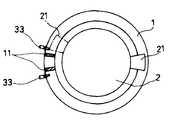
종래 도 1은 일반적으로 사용되었던 로봇 관절부의 작업영역규제장치의 구성도로서, 선회체(2)는 고정베이스(1)에 회전 가능하도록 설치되고, 선회체(2)가 회전함에 따라 선회체(2)에 부착된 스톱퍼(21)를 고정베이스(1)에 부착된 센서(33)가 감지하여 전기적으로 선회체(2)의 작업영역을 규제하게 되어 있다.1 is a configuration diagram of a work area regulation apparatus of a robot joint part which has been generally used, and the revolving
그리고 상기 센서(33)와 일정거리 떨어진 곳에 설치된 쿠션(11)에 의하여 상기 스톱퍼(21)를 더 이상 회전하지 못하도록 함으로써 작업영역을 규제하게 된다.In addition, the
그러나 이러한 일반적인 작업영역 규제장치는 부품이 적게 사용되는 반면 센서(33) 및 쿠션(11)의 설치공간이 필요하고. 더욱이 스톱퍼(21)에 의해 선회체(2)가 도달하지 못하는 영역이 있게 된다.However, such a general work area control device requires less installation space while the
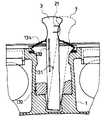
도 2는 미국특허 5,193,658에 공개된 종래의 로봇 작업영역 규제장치로, 선회체(2)는 고정베이스(1)에 회전동작 가능하도록 설치되고, 고정베이스(1)의 홈부에 스톱레버(3)가 삽입되어 있고, 이 스톱레버(3)의 이탈을 방지하기 위한 핀(31)이 스톱레버(3)에 고정되어 있고, 고정베이스(1) 홈의 양측면에는 스톱 레버(3)를 원위치로 복원시키기 위한 탄성체(132)가 설치되어 있고, 스톱레버(3) 상단부와 고정베이스(1) 사이에는 먼지 등 불순물 침입을 방지하기 위한 벨로우(bellow)(134)가 설치되어 있고, 스톱레버(3)에는 레버의 변형을 측정하기 위한 센서(133)가 부착되어 있다. 또한 선회체(2)에 요철형의 홈(22)을 두고 스톱암(21)을 이 요철홈(22)에 고정하여, 선회체(2)의 회전에 의하여 스톱암(21)이 스톱레버(3)와 충돌하게 되면, 스톱레버(3)는 고정베이스(1)의 홈내에서 이동하여 홈의 벽면과 부딪히게 되어 작업영역이 규제되고, 스톱레버(3)의 변형에 따라 센서(133)가 작동하여 로봇의 비상정지(Emergency Stop) 작동하게 되고, 선회체(2)가 로봇의 작업영역 내로 복귀하면 탄성체(132)의 작용에 의하여 소톱레버(3)는 원위치로 되돌아간다.2 is a conventional robot working area restricting device disclosed in US Pat. No. 5,193,658. The
즉, 상기 구성과 작동에 의하여 로봇 관절부의 작업영역을 360도 회전가능하고, 스톱암(22)을 선회관절부 요철홈에 이동설치함에 따라 필요시 관절의 작업영역을 필요한 각도로 조정하도록 하였다.That is, by the above configuration and operation, the robot joint can be rotated by 360 degrees, and the
그런데, 스톱레버(3)의 변형을 감지하여 비상정지하게 됨으로 스톱레버(3)가 고정베이스(1)와 충돌한 후 비상정지하게 되므로 로봇이 손상 받기 쉽고, 변형측정을 위한 센서(133)로 세라믹 튜브(Ceramic tube)를 사용하고, 이 튜브의 절단에 의하여 변형을 감지하므로 원상 복귀되어도 이 세라믹 튜브는 교체하여야 한다.However, since the
또, 벨로우(134), 세라믹 튜브 등을 사용한 복잡한 구조로 제작이 어렵고 고가이다.In addition, it is difficult and expensive to fabricate with a complicated structure using a
본 발명은 상기와 같은 문제점을 해결하기 위한 것으로, 로봇 관절의 작업영역을 360도 까지 회전가능하도록 하며, 필요시 관절의 작업영역을 필요한 각도로 조정하도록 하고, 일반적인 센서로 로봇이 충돌하기 전에 비상정지시킬 수 있는 산업용 로봇의 선회관절 작업영역 규제장치를 제공함에 그 목적이 있다.The present invention is to solve the above problems, it is possible to rotate the work area of the robot joint up to 360 degrees, if necessary to adjust the work area of the joint to the required angle, emergency before the robot collides with a general sensor The object of the present invention is to provide a device for restricting the pivot joint work area of an industrial robot.
상기의 목적을 달성하기 위한 본 발명의 구체적인 수단은, 고정베이스와, 상기 고정베이스 상에서 선회가능하게 설치된 선회체로 구성된 산업용 로봇의 작업영역규제장치에 있어서, 상기 선회체의 저부 원주방향 일지점에 하향 돌출되게 설치된 스톱퍼와, 상기 고정베이스의 원주 방향 일측벽에 소정의 간격으로 입설된 한 쌍의 브래킷과, 상기 브래킷 사이의 고정베이스에 회동가능하게 축설된 축과, 상기 축의 일단에 고정되며 상기 한쌍의 브래킷 사이에서 회동자제되어 상기 스톱퍼의 회전을 제한하도록 설치된 스톱레버로 구성된 것을 특징으로 한다.Specific means of the present invention for achieving the above object, in the work area regulation apparatus of the industrial robot consisting of a fixed base and a pivoting body rotatably provided on the fixed base, the downward circumferential point of the pivoting body A pair of brackets protruded at predetermined intervals on the circumferential side wall of the fixed base, a shaft rotatably arranged on a fixed base between the brackets, and fixed to one end of the shaft It is characterized in that the stop lever is installed between the brackets of the stop lever installed to limit the rotation of the stopper.
도 1은 일반적으로 사용되었던 로봇 관절부의 작업영역 규제장치의 구성도.1 is a configuration diagram of a work area restrictor of the robot joint, which has been generally used.
도 2는 종래 다른 선회관절 규제장치의 평면도.Figure 2 is a plan view of another conventional joint control device.
도 3은 도 2의 A-A선 단면도.3 is a cross-sectional view taken along the line A-A of FIG.
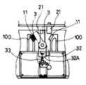
도 4는 본 발명의 실시예에 의한 로봇의 선회관절부 부분 단면도.Figure 4 is a partial cross-sectional view of the pivot joint of the robot according to an embodiment of the present invention.
도 5는 도 4의 Z에서 본 부분단면도.5 is a partial cross-sectional view seen from Z of FIG.
도 6은 본 발명의 실시예에 적용되는 선회관절의 원주상에 형성된 스톱퍼고정구멍의 배치 상태도.Fig. 6 is a layout view of a stopper fixing hole formed on the circumference of the pivot joint applied to the embodiment of the present invention.
<도면의 주요 부분에 대한 부호의 설명><Description of the code | symbol about the principal part of drawing>
1 : 고정베이스 2 : 선회체1: fixed base 2: swinging structure
3 : 스톱레버 20 : 스톱퍼고정구멍3: stop lever 20: stopper fixing hole
21 : 스톱퍼 31 : 축21: stopper 31: shaft
32 : 웨이트레버 33 : 리미트센서32: wait lever 33: limit sensor
이하, 첨부된 도면을 참조하여 본 발명의 실시예를 상세히 설명한다.Hereinafter, with reference to the accompanying drawings will be described an embodiment of the present invention;
도 4 내지 도 6에서와 같이 고정베이스(1)와, 상기 고정베이스(1) 상에서 선회가능하게 설치된 선회체(2)로 구성된 산업용 로봇의 작업영역규제장치에 있어서, 상기 회전체(2) 저부 원주방향으로 다수의 스톱퍼고정구멍(20)을 형성하고, 상기 스톱퍼고정구멍(20)중 어느 하나에 하향 돌출되게 스톱퍼(21)가 볼트(23)로 고정 설치되어 있다.In the work area regulator of the industrial robot, which is composed of a fixed base 1 and a swinging
상기 고정베이스(1)의 원주 방향 일측벽에는 소정의 간격으로 한쌍의 브래킷(100)이 입설되어 있고, 이들 한쌍의 브래킷(100)에는 후술할 스톱레버(3)와 접촉되는 면에 쿠션(11)이 설치되어 있다.A pair of
상기 브래킷(100) 사이에는 상기 고정베이스(1)의 축받이부(1A)에 회동가능한 축(31)이 축설되어 있다.Between the
상기 축(31)의 일단에는 상기 한쌍의 브래킷(100) 사이에서 회동자제되어 상기 스톱퍼(21)의 회전을 제한하도록 하는 스톱레버(3)가 고정 설치되어 있다.At one end of the
그리고 상기 축(31)의 타단에는 상기 스톱레버(3)와 대향되는 위치에 스톱레버보다 무거운 웨이트레버(32)가 고정 설치되어 있고, 상기 웨이트레버(32)의 아래에는 웨이트레버(32)의 회동여부를 감지하는 리미트 센서(33)가 고정브래킷(34)을 매개로 상기 고정베이스(1)상에 부설되어 있다.The other end of the
이와 같이 구성된 본 실시예의 작동상태를 설명한다.The operating state of this embodiment configured as described above will be described.
먼저, 로봇의 제 1축(A)을 중심으로 선회체(2)가 회전하여, 이 선회체(2)에 고정된 스톱퍼(21)가 스톱레버(3)의 일측면을 치게 되면, 스톱레버(3)는 고정베이스(1)의 축받이부(1A)에 설치된 레버 회전축(31)을 중심으로 회전하고, 이와 동시에 웨이트레버(32)가 스톱레버(3)와 같은 방향으로 회전하게 된다.First, when the turning
이때 상기 레버 회전축(31)이 일정각도 이상으로 회전하게 되면 상기 웨이트레버(32)의 원호면(32A)과 리미트 센서(33) 사이의 접촉이 떨어지게 되고, 이 결과 리미트 센서(33)에 연결된 전기회로(도시안됨)에 의하여 로봇이 비상정지하게 된다.At this time, when the
그리고 로봇의 비상정지시 관성력을 갖는 선회체(2)는 스톱레버(3)가 한쌍의 브래킷(100)에 부설된 쿠션(11)에 접촉하게 되면서 더 이상 회전하지 않고 멈추게 된다.And the pivoting body (2) having an inertial force during the emergency stop of the robot stops without rotating any more while the stop lever (3) contacts the cushion (11) attached to the pair of brackets (100).
이후 선회체(2)가 정상적인 작업영역내로 복귀하면, 웨이트레버(32)가 중력에 의하여 회전 모우멘트가 발생하고, 이 웨이트레버(32)의 회전모우멘트는 스톱레버(3)에 의한 회전모우멘트보다 크게 되어 스톱레버(3)는 원위치로 복귀하고, 리미트 센서(33)와 웨이트레버(32)도 다시 접촉하게 되어 로봇은 정상 상태가 된다.Then, when the revolving
한편, 로봇 관절부의 작업영역 범위를 변경하기 위해서는 선회체(2)에 고정된 스톱퍼(21)를 다른 스톱퍼고정구멍(20)에 이동 설치함으로써 작업영역 범위를 변경할 수 있다.On the other hand, in order to change the work area range of the robot joint portion, the work area range can be changed by moving the
상술한 바와 같이 본 발명에 의하면, 중력에 의하여 스톱레버(3)를 복원하게 되므로 별도의 복원장치가 필요 없고, 스톱레버(3)를 고정베이스(1) 외측에 두고 센서(33)를 내측에 두어 불순물 방지를 위한 종래의 밸로우 같은 부품이 필요 없으며, 특수한 센서가 아닌 일반적인 센서를 1개 사용하여 비상정지 작용을 하게 되므로, 구성이 간단하고 신뢰성이 높은 장점이 있다.As described above, according to the present invention, since the
Claims (4)
Translated fromKoreanPriority Applications (1)
| Application Number | Priority Date | Filing Date | Title |
|---|---|---|---|
| KR1019970047121AKR100234663B1 (en) | 1997-09-12 | 1997-09-12 | Apparatus for limiting working area of an industrial robot |
Applications Claiming Priority (1)
| Application Number | Priority Date | Filing Date | Title |
|---|---|---|---|
| KR1019970047121AKR100234663B1 (en) | 1997-09-12 | 1997-09-12 | Apparatus for limiting working area of an industrial robot |
Publications (2)
| Publication Number | Publication Date |
|---|---|
| KR19990025465A KR19990025465A (en) | 1999-04-06 |
| KR100234663B1true KR100234663B1 (en) | 2000-04-01 |
Family
ID=19521235
Family Applications (1)
| Application Number | Title | Priority Date | Filing Date |
|---|---|---|---|
| KR1019970047121AExpired - LifetimeKR100234663B1 (en) | 1997-09-12 | 1997-09-12 | Apparatus for limiting working area of an industrial robot |
Country Status (1)
| Country | Link |
|---|---|
| KR (1) | KR100234663B1 (en) |
- 1997
- 1997-09-12KRKR1019970047121Apatent/KR100234663B1/ennot_activeExpired - Lifetime
Also Published As
| Publication number | Publication date |
|---|---|
| KR19990025465A (en) | 1999-04-06 |
Similar Documents
| Publication | Publication Date | Title |
|---|---|---|
| US4828094A (en) | Motion range limiting apparatus for industrial robots | |
| US5193658A (en) | Adjustable mechanical stop of an industrial robot | |
| US4581609A (en) | X-Y position input device for display system | |
| KR100234663B1 (en) | Apparatus for limiting working area of an industrial robot | |
| US4879499A (en) | Industrial robot's articulate device | |
| JPH10329080A (en) | Robot arm | |
| JP3841237B2 (en) | Robot and load supporting method thereof | |
| JPS601994Y2 (en) | External contact detection device | |
| JP3439935B2 (en) | Work holding device | |
| JPH0347835Y2 (en) | ||
| JP2624928B2 (en) | Elevator door safety devices | |
| JPH06309036A (en) | Rotation axis movement limit position control device | |
| JPH08153Y2 (en) | Rotating mechanical stopper device for articulated robot | |
| JPH0630385Y2 (en) | Rotating shaft stopper device | |
| JPH0634951Y2 (en) | Safety equipment for industrial robots | |
| KR100566619B1 (en) | Automatic tool measuring device | |
| JP2000111306A5 (en) | ||
| JPS6253437B2 (en) | ||
| JPH01210280A (en) | Industrial robot | |
| KR100222951B1 (en) | Apparatus for stopper | |
| KR200154057Y1 (en) | Stopper device | |
| KR100256419B1 (en) | A rotary angle sensing apparatus of a revolutionary instrument | |
| KR0136009Y1 (en) | Orthogonal rotating axis control apparatus of multi-joint robot | |
| JP2812762B2 (en) | Mechanical stopper mechanism | |
| KR100457672B1 (en) | A Sensor for Door/Window-Locking |
Legal Events
| Date | Code | Title | Description |
|---|---|---|---|
| A201 | Request for examination | ||
| PA0109 | Patent application | Patent event code:PA01091R01D Comment text:Patent Application Patent event date:19970912 | |
| PA0201 | Request for examination | Patent event code:PA02012R01D Patent event date:19970912 Comment text:Request for Examination of Application | |
| PG1501 | Laying open of application | ||
| E701 | Decision to grant or registration of patent right | ||
| PE0701 | Decision of registration | Patent event code:PE07011S01D Comment text:Decision to Grant Registration Patent event date:19990626 | |
| GRNT | Written decision to grant | ||
| PR0701 | Registration of establishment | Comment text:Registration of Establishment Patent event date:19990918 Patent event code:PR07011E01D | |
| PR1002 | Payment of registration fee | Payment date:19990918 End annual number:3 Start annual number:1 | |
| PG1601 | Publication of registration | ||
| PR1001 | Payment of annual fee | Payment date:20020919 Start annual number:4 End annual number:4 | |
| PR1001 | Payment of annual fee | Payment date:20030918 Start annual number:5 End annual number:5 | |
| PR1001 | Payment of annual fee | Payment date:20040825 Start annual number:6 End annual number:6 | |
| PR1001 | Payment of annual fee | Payment date:20050907 Start annual number:7 End annual number:7 | |
| PR1001 | Payment of annual fee | Payment date:20060919 Start annual number:8 End annual number:8 | |
| PR1001 | Payment of annual fee | Payment date:20070917 Start annual number:9 End annual number:9 | |
| PR1001 | Payment of annual fee | Payment date:20080715 Start annual number:10 End annual number:10 | |
| PR1001 | Payment of annual fee | Payment date:20090903 Start annual number:11 End annual number:11 | |
| PR1001 | Payment of annual fee | Payment date:20100909 Start annual number:12 End annual number:12 | |
| PR1001 | Payment of annual fee | Payment date:20110916 Start annual number:13 End annual number:13 | |
| FPAY | Annual fee payment | Payment date:20120910 Year of fee payment:14 | |
| PR1001 | Payment of annual fee | Payment date:20120910 Start annual number:14 End annual number:14 | |
| FPAY | Annual fee payment | Payment date:20130911 Year of fee payment:15 | |
| PR1001 | Payment of annual fee | Payment date:20130911 Start annual number:15 End annual number:15 | |
| FPAY | Annual fee payment | Payment date:20140828 Year of fee payment:16 | |
| PR1001 | Payment of annual fee | Payment date:20140828 Start annual number:16 End annual number:16 | |
| FPAY | Annual fee payment | Payment date:20150826 Year of fee payment:17 | |
| PR1001 | Payment of annual fee | Payment date:20150826 Start annual number:17 End annual number:17 | |
| FPAY | Annual fee payment | Payment date:20160905 Year of fee payment:18 | |
| PR1001 | Payment of annual fee | Payment date:20160905 Start annual number:18 End annual number:18 | |
| EXPY | Expiration of term | ||
| PC1801 | Expiration of term | Termination date:20180312 Termination category:Expiration of duration |