KR100223193B1 - Multipurpose Projection Display - Google Patents
Multipurpose Projection DisplayDownload PDFInfo
- Publication number
- KR100223193B1 KR100223193B1KR1019970023498AKR19970023498AKR100223193B1KR 100223193 B1KR100223193 B1KR 100223193B1KR 1019970023498 AKR1019970023498 AKR 1019970023498AKR 19970023498 AKR19970023498 AKR 19970023498AKR 100223193 B1KR100223193 B1KR 100223193B1
- Authority
- KR
- South Korea
- Prior art keywords
- screen
- projection display
- image light
- reflector
- transmissive screen
- Prior art date
- Legal status (The legal status is an assumption and is not a legal conclusion. Google has not performed a legal analysis and makes no representation as to the accuracy of the status listed.)
- Expired - Fee Related
Links
Images


Classifications
- H—ELECTRICITY
- H04—ELECTRIC COMMUNICATION TECHNIQUE
- H04N—PICTORIAL COMMUNICATION, e.g. TELEVISION
- H04N5/00—Details of television systems
- H04N5/74—Projection arrangements for image reproduction, e.g. using eidophor
Landscapes
- Engineering & Computer Science (AREA)
- Multimedia (AREA)
- Signal Processing (AREA)
- Projection Apparatus (AREA)
- Transforming Electric Information Into Light Information (AREA)
- Devices For Indicating Variable Information By Combining Individual Elements (AREA)
Abstract
Translated fromKoreanDescription
Translated fromKorean본 발명은 프로젝션 디스플레이장치에 관한 것으로, 특히 배면방식(rear type) 및 전면방식(front type)을 모두 사용할 수 있는 다목적 프로젝션 디스플레이장치에 관한 것이다.BACKGROUND OF THE
종래의 프로젝션 디스플레이장치는 배면방식 및 전면방식을 모두 사용하기 위해 여러 가지 방식을 제시하였다.Conventional projection display devices have been proposed in various ways to use both the back method and the front method.
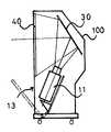
도 1 및 도 2는 종래의 프로젝션 디스플레이장치를 도시한 도면이다. 도 1은 렌즈와 반사경 등을 내부에 구비한 프로젝터(projector)(11)를 나타낸 것이다. 이 프로젝터(11)를 통해 전면스크린(50)에 전면방식으로 영상광을 결상한다. 도 1b는 프로젝터(11)를 디스플레이장치의 캐비넷(100) 내부에 설치한 것을 설명하기 위한 도면이다. 도시된 바와같이, 디스플레이장치는 캐비넷(100) 내부에 프로젝터(11)를 설치할 수 있는 통로인 문(door)(13)을 구비하며, 프로젝터(11)는 캐비넷(100) 내부의 적정위치에 설치된다. 디스플레이장치의 캐비넷(100) 내부에 설치된 프로젝터(11)는 반사경(30)을 통한 배면방식으로 배면스크린(40)에 영상광을 결상한다. 따라서, 도 1에 도시된 종래의 프로젝션 디스플레이장치는 프로젝터(projector)(11)를 디스플레이장치의 캐비넷(100) 내부에 장착하여 배면방식을 사용할 수 있고, 캐비넷(100) 외부에서는 전면방식을 사용할 수 있으므로, 2가지 방식을 실현할 수 있다.1 and 2 illustrate a conventional projection display apparatus. 1 shows a
도 2에 도시된 종래의 프로젝션 디스플레이장치는 내부 광학계의 반사경 및 줌렌즈 등을 이용하여 전면방식으로 영상광을 외부스크린에 결상한다. 한편, 프로젝션 디스플레이장치에 부착된 소형의 배면스크린(40)을 통해 배면방식으로 전환하여 2가지 방식을 실현할 수 있다.The conventional projection display device illustrated in FIG. 2 forms image light on an external screen in a front-side manner by using a reflector and a zoom lens of an internal optical system. On the other hand, by switching to the rear method through the small
그러나, 도 1에 도시된 종래의 프로젝션 디스플레이장치는 프로젝터를 착탈하는 번거로움 및 생산 가격상승의 문제가 있고, 도 2에 도시된 종래의 프로젝션 디스플레이장치는 스크린에 화면을 결상시키기 위해 반사경의 반사 및 구동 매커니즘이 복합적으로 적용되며, 스크린이 프로젝션 디스플레이장치 셋트에 부착되어 있으므로, 배면투사시에는 작은 화면만 디스플레이가 가능한 불편함이 있었다.However, the conventional projection display device shown in FIG. 1 has a problem of the hassle of attaching and detaching a projector and the increase in production price, and the conventional projection display device shown in FIG. Since the driving mechanism is applied in combination, and the screen is attached to the projection display apparatus set, there was an inconvenience that only a small screen can be displayed during the rear projection.
따라서, 본 발명의 목적은 위와같은 문제점을 개선하기 위해 반사경으로부터 반사된 영상광의 광경로로부터 제거가능한 투과형 스크린을 채용하여 배면 및 전면의 2가지 방식을 모두 적용할 수 있는 다목적 프로젝션 디스플레이장치를 제공함에 있다.Accordingly, an object of the present invention is to provide a multi-purpose projection display device that can be applied to both the back and the front by adopting a transmissive screen that can be removed from the optical path of the image light reflected from the reflector to improve the above problems. have.
도 1 및 도 2는 종래의 프로젝션 디스플레이장치를 도시한 도면,1 and 2 show a conventional projection display device;
도 3은 본 발명의 바람직한 일 실시예에 따른 다목적 프로젝션 디스플레이장치를 도시한 도면,3 is a view showing a multi-purpose projection display device according to an embodiment of the present invention;
도 4는 도 3장치의 사용실시예를 보여주는 도면,4 shows an embodiment of the use of the device of FIG. 3;
도 5 및 도 6은 본 발명의 타실시예를 설명하기 위해 투사형스크린을 도시한 도면.5 and 6 illustrate a projection screen for explaining another embodiment of the present invention.
※ 도면의 주요 부분에 대한 부호의 설명※ Explanation of codes for main parts of drawing
10 : 광학계20 : 기타회로기판10: optical system 20: other circuit board
30 : 반사경60 : 제어부30: reflector 60: control unit
70 : 구동부100 : 캐비넷70: driving unit 100: cabinet
200 : 투과형 스크린300 : 렌즈부200: transmission screen 300: lens unit
위와같은 목적을 달성하기 위한 본 발명의 특징은 프로젝션 디스플레이장치에 있어서, 베이스, 상기 베이스에 설치되는 투과형 스크린, 영상광의 투사를 위한 광학계 및 상기 광학계로부터 투사된 영상광을 상기 투과형 스크린을 향하도록 반사시키는 반사경을 포함하고, 상기 투과형 스크린을 상기 반사경으로부터 반사된 영상광의 광경로로부터 제거가능한 것을 특징으로 하는 프로젝션 디스플레이장치에 있다.A feature of the present invention for achieving the above object is a projection display device, a base, a transmissive screen mounted on the base, an optical system for projecting image light and the image light projected from the optical system to reflect toward the transmissive screen And a reflective mirror, wherein the transmissive screen is removable from the optical path of the image light reflected from the reflective mirror.
이하, 첨부한 도면들을 참조하여 본 발명의 바람직한 일 실시예를 상세히 설명하겠다.Hereinafter, exemplary embodiments of the present invention will be described in detail with reference to the accompanying drawings.
도 3은 본 발명의 다목적 프로젝션 디스플레이장치의 내부구성을 측면에서 나타낸 것이다.Figure 3 shows the internal structure of the multi-purpose projection display device of the present invention in terms of.
도 3에서, 본 발명의 프로젝션 디스플레이장치는 렌즈를 포함한 광학계(10)와 프로젝션 디스플레이장치를 구동하는데 사용되는 기타회로기판(20) 및 반사경(30)을 구비한다. 그리고, 반사경(30)에서 반사된 상을 투과 또는 결상시키는 투과형 스크린(200)을 구비한다. 또한, 본 발명의 장치는 제어부(60)와, 제어부(60)의 제어하에 투과형 스크린(200)을 구동하는 구동부(70)를 구비한다. 캐비넷(100)은 청구범위에서 베이스로 이야기되는 것으로, 광학계(10), 렌즈부(300)와, 기타회로기판(20), 반사경(30), 제어부(60) 및 구동부(70)가 설치되는 부분이다. 광학계(10)의 렌즈부(300)는 줌(zoom), 포커스(focus), 디센타(decenter)기능 등을 수행할 수 있다. 여기서, 디센타기능은 전면스크린(50)에 영상광을 결상시켰을 때 사용되는 기능으로써, 영상광의 출력각도를 조절하여 사용자의 시각에 따라 화면의 중심을 이동시키는 것을 의미한다. 즉, 전면스크린(50)에 결상되는 영상광의 중심을 아래 또는 위로 조정하여 사용자가 위치한 지점에서의 화면각도를 조절할 수 있다. 본 발명의 실시예에서, 광학계(10)는 CRT 및 액정판넬이 모두 사용가능하며, 보다 바람직하게는 액정판넬을 사용한다. 그 이유는 액정판넬이 CRT보다 소형이므로 프로젝션 디스플레이장치의 캐비넷(100) 내부에서의 배치제한이 적고 중량도 삭감되기 때문이다.In FIG. 3, the projection display apparatus of the present invention includes an
도 4는 도 3의 장치의 사용 실시예를 보여주는 도면이다. 도 4a에 도시된 바와같이, 전면방식으로 사용하고자할 때, 투과형스크린(200)은 반사경(30)에서 반사된 영상광을 모두 투과하여 전면스크린(50)에 결상되도록한다. 그러므로, 사용자는 전면스크린(50)에 결상된 영상광을 볼 수 있다. 한편, 도 4b에 도시된 바와같이, 배면방식으로 사용하고자할 때, 투과형스크린(200)은 반사경(30)에서 반사된 영상광을 결상시켜 사용자가 볼 수 있도록 한다.4 shows an embodiment of the use of the device of FIG. 3. As shown in FIG. 4A, when using the front surface, the
이제, 본 발명에 따른 전면 및 배면방식을 모두 수용하는 다목적 프로젝션 디스플레이장치의 실시예들을 설명하겠다.Now, embodiments of the multi-purpose projection display device that accommodates both the front and rear methods according to the present invention will be described.
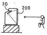
본 발명의 제 1실시예로, 본 발명의 프로젝션 디스플레이장치는 캐비넷(100)의 전면부에 착탈가능한 투과형 스크린(200)을 제시한다. 그러므로, 투과형 스크린(200)을 프로젝션 디스플레이장치의 캐비넷(100)에 부착하였을때에는 배면방식(rear type)이 적용된다(도 4b참조). 즉, 투과형 스크린(200)에 영상광을 결상함으로써 일반적인 프로젝션 디스플레이장치의 기능을 수행한다. 한편, 투과형 스크린(200)을 떼어내었을때에는 전면스크린(50)에 영상광이 결상되는 전면방식(front type)이 적용된다(도 4a참조).In a first embodiment of the present invention, the projection display device of the present invention presents a
본 발명의 제 2실시예로, 도 5에 도시된 바와같이, 전기적으로 구동되는 전자스크린을 투과형 스크린(200)으로 사용하는 방법을 제시한다. 이 전자스크린은 투과 및 화면결상을 모두 가능하게 하는 스크린이다. 제어부(60)의 제어에 따라 전원이 인가되면, 투과형스크린(200)은 투명하게되어(A) 반사경(30)에서 반사된 영상광을 모두 투과한다. 그러므로, 투과된 영상광은 전면스크린(50)에 결상되어 전면방식이 적용된다(도 4a참조). 한편, 전원을 인가하지 않으면, 투과형스크린(200)은 반투명하게되어(B) 반사경(30)에서 반사된 영상광은 투과형스크린(200)에 결상되어 배면방식이 적용된다(도 4b참조).As a second embodiment of the present invention, as shown in FIG. 5, a method of using an electrically driven electronic screen as the
본 발명의 제 3실시예로, 도 6a에 도시된 바와같이, 한면(A)은 전면방식의 스크린으로 사용할 수 있도록 투명하고, 인접한 다른 한면(B)은 배면방식의 스크린으로 사용할 수 있도록 반투명하게 설계된 투과형 스크린(200)을 제시한다. 이 투과형 스크린은 도 6b에 도시된 바와같이, 롤(roll)형태로 구성하여 전면 또는 배면방식에 따라 이동하게 한다. 즉, 전면방식의 스크린으로 사용하고자할 경우에는 A면이 프로젝션 디스플레이장치 캐비넷(100)의 전면으로 오게하여 반사경(30)에서 반사된 영상광을 투과한다. 그러므로, 반사경(30)에서 반사된 영상광은 전면스크린(50)에 결상된다(도 4a참조). 한편, 배면방식의 스크린으로 사용하고자할 경우 B면이 프로젝션 디스플레이장치의 캐비넷(100)의 전면에 오게하여 반사경(30)에서 반사된 영상광을 결상한다(도 4b참조). 본 발명의 제 3실시예에서, 투과형 스크린은 프로젝션 디스플레이장치 캐비넷(100)의 측면에 수납가능하도록 구성한다.In a third embodiment of the present invention, as shown in Fig. 6A, one side A is transparent for use as a front screen, and the other adjacent side B is translucent for use as a back screen. The designed
상술한 바와같이, 본 발명은 다목적 프로젝션 디스플레이장치에 관한 것으로, 투과형 스크린과, 영상광의 투사를 위한 광학계, 광학계로부터 투사된 영상광을 상기 투과형 스크린을 향하도록 반사시키는 반사경을 포함하고, 투과형 스크린을 상기 반사경으로부터 반사된 영상광의 광경로로부터 제거가능하게 하여 전면 및 배면투사방식을 가능하게 함으로써 다목적으로 활용할 수 있는 효과가 있다.As described above, the present invention relates to a multi-purpose projection display device, comprising a transmissive screen, an optical system for projecting image light, a reflector reflecting the image light projected from the optical system toward the transmissive screen, It is possible to remove the image light reflected from the reflector from the optical path to enable the front and rear projection method has an effect that can be utilized for multi-purpose.
Claims (7)
Translated fromKoreanPriority Applications (2)
| Application Number | Priority Date | Filing Date | Title |
|---|---|---|---|
| KR1019970023498AKR100223193B1 (en) | 1997-06-07 | 1997-06-07 | Multipurpose Projection Display |
| JP10159305AJPH1172843A (en) | 1997-06-07 | 1998-06-08 | Projection display device |
Applications Claiming Priority (1)
| Application Number | Priority Date | Filing Date | Title |
|---|---|---|---|
| KR1019970023498AKR100223193B1 (en) | 1997-06-07 | 1997-06-07 | Multipurpose Projection Display |
Publications (2)
| Publication Number | Publication Date |
|---|---|
| KR19990000535A KR19990000535A (en) | 1999-01-15 |
| KR100223193B1true KR100223193B1 (en) | 1999-10-15 |
Family
ID=19508851
Family Applications (1)
| Application Number | Title | Priority Date | Filing Date |
|---|---|---|---|
| KR1019970023498AExpired - Fee RelatedKR100223193B1 (en) | 1997-06-07 | 1997-06-07 | Multipurpose Projection Display |
Country Status (2)
| Country | Link |
|---|---|
| JP (1) | JPH1172843A (en) |
| KR (1) | KR100223193B1 (en) |
Families Citing this family (3)
| Publication number | Priority date | Publication date | Assignee | Title |
|---|---|---|---|---|
| US7426804B2 (en) | 2002-02-06 | 2008-09-23 | Andersen Corporation | Specialty display window |
| US6988339B2 (en) | 2002-02-06 | 2006-01-24 | Andersen Corporation | Specialty media window |
| SE529078C2 (en)* | 2005-07-26 | 2007-04-24 | Optea Ab | Projector for projecting images and movies onto a projection surface and system for projecting navigation information |
Citations (1)
| Publication number | Priority date | Publication date | Assignee | Title |
|---|---|---|---|---|
| JPS6077173U (en)* | 1983-11-01 | 1985-05-29 | 三菱電機株式会社 | Projection television receiver |
- 1997
- 1997-06-07KRKR1019970023498Apatent/KR100223193B1/ennot_activeExpired - Fee Related
- 1998
- 1998-06-08JPJP10159305Apatent/JPH1172843A/enactivePending
Patent Citations (1)
| Publication number | Priority date | Publication date | Assignee | Title |
|---|---|---|---|---|
| JPS6077173U (en)* | 1983-11-01 | 1985-05-29 | 三菱電機株式会社 | Projection television receiver |
Also Published As
| Publication number | Publication date |
|---|---|
| JPH1172843A (en) | 1999-03-16 |
| KR19990000535A (en) | 1999-01-15 |
Similar Documents
| Publication | Publication Date | Title |
|---|---|---|
| KR20020010966A (en) | Optical system for head mount display | |
| JP2004514925A (en) | Dual mode system of peeping and projection display | |
| JP2002526791A (en) | Optical docking station | |
| EP1211901A2 (en) | Aperture element for a video projector and a video projector using the aperture element | |
| JPH06181558A (en) | Multi-screen projection monitor | |
| KR100223193B1 (en) | Multipurpose Projection Display | |
| JP2000019636A (en) | Projection display device and control method of projection display device | |
| JP2001255488A (en) | Projection type on-vehicle video display device | |
| KR0166172B1 (en) | Liquid crystal display device and projector using the same | |
| JP2000019637A (en) | Projection display device | |
| CN100555064C (en) | Rear projection | |
| JPH0862721A (en) | liquid crystal television | |
| KR101125175B1 (en) | Back light unit of hud system for automotive vehicles | |
| JP2000010503A (en) | Video display device | |
| JPH0749533A (en) | Projector device | |
| JP3330069B2 (en) | Video display device | |
| JP3328821B2 (en) | Image display device | |
| JPS6232431A (en) | projector device | |
| JP2000089360A (en) | Projection display device | |
| JPH11196352A (en) | Head mounted video display | |
| KR0141837B1 (en) | Lcd projector | |
| KR0134054Y1 (en) | Lamp fixing structure for projector | |
| KR200153799Y1 (en) | LCD projector with screen adjustment means | |
| KR200159878Y1 (en) | Lcd display device of finder in a camera | |
| KR930004643B1 (en) | 3-panel LCD projector with CPT |
Legal Events
| Date | Code | Title | Description |
|---|---|---|---|
| A201 | Request for examination | ||
| PA0109 | Patent application | St.27 status event code:A-0-1-A10-A12-nap-PA0109 | |
| PA0201 | Request for examination | St.27 status event code:A-1-2-D10-D11-exm-PA0201 | |
| R17-X000 | Change to representative recorded | St.27 status event code:A-3-3-R10-R17-oth-X000 | |
| R18-X000 | Changes to party contact information recorded | St.27 status event code:A-3-3-R10-R18-oth-X000 | |
| PG1501 | Laying open of application | St.27 status event code:A-1-1-Q10-Q12-nap-PG1501 | |
| PN2301 | Change of applicant | St.27 status event code:A-3-3-R10-R13-asn-PN2301 St.27 status event code:A-3-3-R10-R11-asn-PN2301 | |
| E902 | Notification of reason for refusal | ||
| PE0902 | Notice of grounds for rejection | St.27 status event code:A-1-2-D10-D21-exm-PE0902 | |
| P11-X000 | Amendment of application requested | St.27 status event code:A-2-2-P10-P11-nap-X000 | |
| P13-X000 | Application amended | St.27 status event code:A-2-2-P10-P13-nap-X000 | |
| E701 | Decision to grant or registration of patent right | ||
| PE0701 | Decision of registration | St.27 status event code:A-1-2-D10-D22-exm-PE0701 | |
| GRNT | Written decision to grant | ||
| PR0701 | Registration of establishment | St.27 status event code:A-2-4-F10-F11-exm-PR0701 | |
| PR1002 | Payment of registration fee | St.27 status event code:A-2-2-U10-U11-oth-PR1002 Fee payment year number:1 | |
| PN2301 | Change of applicant | St.27 status event code:A-5-5-R10-R13-asn-PN2301 St.27 status event code:A-5-5-R10-R11-asn-PN2301 | |
| PG1601 | Publication of registration | St.27 status event code:A-4-4-Q10-Q13-nap-PG1601 | |
| R18-X000 | Changes to party contact information recorded | St.27 status event code:A-5-5-R10-R18-oth-X000 | |
| PN2301 | Change of applicant | St.27 status event code:A-5-5-R10-R13-asn-PN2301 St.27 status event code:A-5-5-R10-R11-asn-PN2301 | |
| PR1001 | Payment of annual fee | St.27 status event code:A-4-4-U10-U11-oth-PR1001 Fee payment year number:4 | |
| R18-X000 | Changes to party contact information recorded | St.27 status event code:A-5-5-R10-R18-oth-X000 | |
| R18-X000 | Changes to party contact information recorded | St.27 status event code:A-5-5-R10-R18-oth-X000 | |
| PR1001 | Payment of annual fee | St.27 status event code:A-4-4-U10-U11-oth-PR1001 Fee payment year number:5 | |
| R18-X000 | Changes to party contact information recorded | St.27 status event code:A-5-5-R10-R18-oth-X000 | |
| PR1001 | Payment of annual fee | St.27 status event code:A-4-4-U10-U11-oth-PR1001 Fee payment year number:6 | |
| PR1001 | Payment of annual fee | St.27 status event code:A-4-4-U10-U11-oth-PR1001 Fee payment year number:7 | |
| PN2301 | Change of applicant | St.27 status event code:A-5-5-R10-R13-asn-PN2301 St.27 status event code:A-5-5-R10-R11-asn-PN2301 | |
| PN2301 | Change of applicant | St.27 status event code:A-5-5-R10-R13-asn-PN2301 St.27 status event code:A-5-5-R10-R11-asn-PN2301 | |
| PR1001 | Payment of annual fee | St.27 status event code:A-4-4-U10-U11-oth-PR1001 Fee payment year number:8 | |
| FPAY | Annual fee payment | Payment date:20070628 Year of fee payment:9 | |
| PR1001 | Payment of annual fee | St.27 status event code:A-4-4-U10-U11-oth-PR1001 Fee payment year number:9 | |
| LAPS | Lapse due to unpaid annual fee | ||
| PC1903 | Unpaid annual fee | St.27 status event code:A-4-4-U10-U13-oth-PC1903 Not in force date:20080709 Payment event data comment text:Termination Category : DEFAULT_OF_REGISTRATION_FEE | |
| PC1903 | Unpaid annual fee | St.27 status event code:N-4-6-H10-H13-oth-PC1903 Ip right cessation event data comment text:Termination Category : DEFAULT_OF_REGISTRATION_FEE Not in force date:20080709 | |
| R18-X000 | Changes to party contact information recorded | St.27 status event code:A-5-5-R10-R18-oth-X000 | |
| P22-X000 | Classification modified | St.27 status event code:A-4-4-P10-P22-nap-X000 |