KR100222246B1 - A protector direction transverse apparatus - Google Patents
A protector direction transverse apparatusDownload PDFInfo
- Publication number
- KR100222246B1 KR100222246B1KR1019970033324AKR19970033324AKR100222246B1KR 100222246 B1KR100222246 B1KR 100222246B1KR 1019970033324 AKR1019970033324 AKR 1019970033324AKR 19970033324 AKR19970033324 AKR 19970033324AKR 100222246 B1KR100222246 B1KR 100222246B1
- Authority
- KR
- South Korea
- Prior art keywords
- protector
- shaft
- angle adjusting
- cable
- vehicle
- Prior art date
- Legal status (The legal status is an assumption and is not a legal conclusion. Google has not performed a legal analysis and makes no representation as to the accuracy of the status listed.)
- Expired - Fee Related
Links
Images


Classifications
- B—PERFORMING OPERATIONS; TRANSPORTING
- B60—VEHICLES IN GENERAL
- B60R—VEHICLES, VEHICLE FITTINGS, OR VEHICLE PARTS, NOT OTHERWISE PROVIDED FOR
- B60R16/00—Electric or fluid circuits specially adapted for vehicles and not otherwise provided for; Arrangement of elements of electric or fluid circuits specially adapted for vehicles and not otherwise provided for
- B60R16/02—Electric or fluid circuits specially adapted for vehicles and not otherwise provided for; Arrangement of elements of electric or fluid circuits specially adapted for vehicles and not otherwise provided for electric constitutive elements
- B60R16/0207—Wire harnesses
- B60R16/0215—Protecting, fastening and routing means therefor
- H—ELECTRICITY
- H02—GENERATION; CONVERSION OR DISTRIBUTION OF ELECTRIC POWER
- H02G—INSTALLATION OF ELECTRIC CABLES OR LINES, OR OF COMBINED OPTICAL AND ELECTRIC CABLES OR LINES
- H02G3/00—Installations of electric cables or lines or protective tubing therefor in or on buildings, equivalent structures or vehicles
- H02G3/02—Details
- H02G3/04—Protective tubing or conduits, e.g. cable ladders or cable troughs
- H—ELECTRICITY
- H02—GENERATION; CONVERSION OR DISTRIBUTION OF ELECTRIC POWER
- H02G—INSTALLATION OF ELECTRIC CABLES OR LINES, OR OF COMBINED OPTICAL AND ELECTRIC CABLES OR LINES
- H02G3/00—Installations of electric cables or lines or protective tubing therefor in or on buildings, equivalent structures or vehicles
- H02G3/26—Installations of cables, lines, or separate protective tubing therefor directly on or in walls, ceilings, or floors
Landscapes
- Engineering & Computer Science (AREA)
- Mechanical Engineering (AREA)
- Details Of Indoor Wiring (AREA)
Abstract
Translated fromKoreanDescription
Translated fromKorean본 발명은 프로텍터의 방향 전환장치에 관한 것으로, 좀더 상세하게는 프로텍터에 방향성을 주어 여러 방향으로 케이블을 배열하며, 케이블을 보호할 수 있도록 하는 프로텍터의 방향 전환장치에 관한 것이다.The present invention relates to a direction changer of the protector, and more particularly, to a direction changer of the protector to arrange the cables in various directions by giving the protector the direction, and to protect the cable.
일반적으로 프로텍터는 차량에 필요한 각종 전장품, 전조등 등에 전원을 공급하는 케이블을 고정되게 하는 것으로, 그 종류는 차체의 형상에 따라 일자형, 일 측이 절곡된 형태등 여러 가지 형태로 나누어진다.In general, the protector is to fix the cable for supplying power to various electrical appliances, headlights, etc. required for the vehicle, and the type is divided into various types such as straight shape and one side bent according to the shape of the vehicle body.
도 1은 종래의 일자형 프로텍터가 사용되는 상태를 보인 사용상태도이고, 도 2는 종래의 일 측이 절곡된 형태의 프로텍터가 사용되는 상태를 보인 사용상태도이다.1 is a state diagram showing a state in which a conventional linear protector is used, Figure 2 is a state diagram showing a state in which a conventional one-sided protector is used.
도 1 및 도 2에 도시된 바와 같이, 종래에는 차량에 필요한 전원을 공급할 수 있도록 하는 케이블을 차체에 고정되게 하는 몸체(10)가 구비되고, 상기 몸체(10)에는 케이블이 삽입될 수 있도록 길이 방향으로 관통되는 삽입홀(12:미도시)과, 상기 몸체(10)가 차체에 고정될 수 있도록 상기 몸체(10) 일측에 복수개의 고정돌기(13)가 형성되고, 상기 고정돌기(13)에는 통상적인 고정부재 즉, 볼트에 의해 차체에 고정될 수 있도록 고정홀(14)이 형성된다.As shown in Figure 1 and 2, conventionally provided with a
상기와 같이 구성된 종래의 프로텍터(10)는 차체에 케이블을 고정되게 할 때 차체의 형상에 맞는 프로텍터를 이용하여 설치해야 하므로 작업자가 일일이 프로텍터(10)를 차체의 형상과 비교해야 한다는 문제점이 발생하였다.The
따라서, 본 발명의 목적은 상기와 같은 문제점을 해결하기 위한 것으로, 프로텍터에 방향성을 주어 여러 방향으로 케이블을 배열할 수 있도록 하는 프로텍터의 방향 전환장치를 제공하는 것이다.Accordingly, an object of the present invention is to solve the above problems, and to provide a protector direction switching device that can arrange the cables in various directions by giving the protector direction.
도 1은 종래의 일자형 프로텍터가 사용되는 상태를 보인 사용상태도.1 is a use state showing a state in which a conventional linear protector is used.
도 2는 종래의 일 측이 절곡된 형태의 프로텍터가 사용되는 상태를 보인 사용상태도Figure 2 is a use state showing a state in which a conventional protector of one side is used bent form
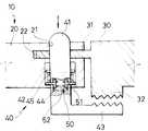
도 3은 본 발명에 의한 프로텍터의 방향 전환장치의 구성을 보인 측단면도.Figure 3 is a side cross-sectional view showing the configuration of the apparatus for changing the direction of the protector according to the present invention.
도 4는 본 발명에 의한 프로텍터의 방향 전환장치의 작동상태를 보인 사용상태도.Figure 4 is a use state showing the operating state of the direction changer of the protector according to the present invention.
* 도면의 주요부분에 대한 부호의 설명* Explanation of symbols for main parts of the drawings
10 : 프로텍터 11 : 몸체10: protector 11: body
12 : 삽입홀 13 : 고정돌기12: insertion hole 13: fixing protrusion
14 : 고정홀 20 : 몸체114: fixing hole 20: body 1
21 : 삽입홀 22 : 결합공21: insertion hole 22: coupling hole
30 : 몸체2 31 : 삽입돌기30: body 2 31: insertion protrusion
32 : 기어부 40 : 각도조절수단32: gear portion 40: angle adjusting means
41 : 샤프트 42 : 걸림턱41: shaft 42: locking jaw
43 : 각도조절부재 44 : 걸림홀43: angle adjustment member 44: locking hole
45 : 탄성부재 50 : 걸림수단45: elastic member 50: locking means
51 : 걸림돌기 52 : 탄지부재51: engaging projection 52: the finger member
상기한 목적을 달성하기 위한 본 발명은 차량의 각종 전장품 등에 전원이 인가되게 하는 케이블을 고정시킬 수 있도록 한 쌍으로 대응되게 구성되는 몸체1, 2와, 상기 몸체1이 좌, 우로 방향성을 가질 수 있도록 상기 몸체1에 형성된 결합공에 삽입되는 각도조절수단을 포함하여 구성되는 것을 특징으로 한다.The present invention for achieving the above object is the body 1, 2 and the body 1 is configured to correspond to the pair to be fixed to the cable to be applied power to various electrical appliances of the vehicle, the body 1 may have a left, right direction Characterized in that it comprises an angle adjusting means which is inserted into the coupling hole formed in the body 1.
이하 도면에 도시된 바와 같은 실시예를 참고로 하여 프로텍터의 방향 전환장치의 구성을 보면 다음과 같다.Referring to the configuration of the apparatus for changing the direction of the protector with reference to the embodiment as shown in the drawings as follows.
도 3은 본 발명에 의한 프로텍터의 방향 전환장치의 구성을 보인 측단면도이며, 도 4는 본 발명에 의한 프로텍터의 방향 전환장치의 작동상태를 보인 사용상태도이다.Figure 3 is a side cross-sectional view showing the configuration of the direction change device of the protector according to the present invention, Figure 4 is a state diagram showing the operating state of the direction change device of the protector according to the present invention.
도 3 내지 도 4에 도시한 바와 같이 본 발명은 차량의 각종 전장품 등에 전원이 인가되게 하는 케이블을 고정시킬 수 있도록 한 쌍으로 대응되게 구성되는 몸체1, 2(20, 30)와, 상기 몸체1(20)이 좌, 우로 방향성을 가질 수 있도록 상기 몸체1(20)에 형성된 결합공(22)에 삽입되는 각도조절수단(40)으로 구성된다.As shown in Figures 3 to 4 the present invention is the body 1, 2 (20, 30) and the body 1 is configured to correspond to the pair to be fixed to the cable to be applied power to various electrical appliances of the vehicle, and the body 1 Consists of the angle adjusting means 40 is inserted into the
상기 프로텍터(10)는 몸체1(20)과, 몸체2(30)로 구성된다.The
상기 몸체2(20)는 한쌍으로 구성된 상기 프로텍터(10)가 서로 결합될 수 있도록 상기 몸체2(30) 일측에 삽입돌기(31)가 형성되고, 상기 몸체1(20)에는 상기 몸체2(30)에 형성된 삽입돌기(31)가 삽입되어 하나의 프로텍터(10)가 될 수 있도록 상기 삽입돌기(31)의 대응되는 곳에 삽입홈(21)이 형성되고, 상기 각도조절수단(40)에 의해 상기 프로텍터(10)가 접혀질 수 있도록 상기 몸체2(30)의 하단 소정 위치에 기어부(32)가 일체로 형성된다.The body 2 (20) is formed with an
상기 각도조절수단(40)은 샤프트(41)와, 각도조절부재(43)와, 걸림수단(50)으로 구성된다.The angle adjusting means 40 is composed of a
상기 샤프트(41)는 상기 프로텍터(10)가 방향성을 가질 수 있도록 원기둥의 형상을 가지며 상기 몸체1(20)에 형성된 삽입홀(21)에 삽입된다. 상기 샤프트(41)가 작업자에 의해 눌려진 후 다시 복원될 수 있도록 하는 탄성부재(45)가 상기 삽입홀(21)에 설치된다.The
상기 샤프트(41)에는 상기 탄성부재(45)에 의해 지지될 수 있도록, 즉 상기 몸체1과 몸체2가 샤프트를 중심으로 상대적으로 회전할 수 있도록 샤프트(41)의 소정 위치에 형성되는 복수개의 걸림턱(42)과, 상기 샤프트(41)가 상기 몸체1(20)의 결합공(22)에서 이탈되는 것을 방지하며 상기 탄성부재(45)의 하단부를 지지할 수 있도록 상기 샤프트(41)의 소정 위치에 구비되는 걸림수단(50)과, 상기 몸체2(30)의 하부에 설치된 기어부(32)와 맞물려 프로텍터(10)가 방향성을 가질 수 있도록 상기 샤프트(41) 하단에 일체로 각도조절부재(43)가 형성된다.A plurality of hooks are formed at the predetermined positions of the
그리고, 상기 샤프트(41)에는 상기 걸림수단(50)이 설치될 수 있도록 소정 위치에 걸림홀(44)이 형성된다.The
상기 걸림수단은 복수개의 걸림돌기(51)와, 탄지부재(52)로 구성된다.The locking means is composed of a plurality of
상기 걸림돌기(51)는 아래에서 설명할 탄지부재(52)의 탄성력에 의해 상기 샤프트(41)가 상기 몸체1(20)에서 이탈되는 것을 방지할 수 있도록 상기 걸림홀(44)에 설치되고, 상기 탄성부재(52)는 상기 샤프트(41)가 상기 몸체1(20)의 삽입홀(21)에서 이탈되는 것을 방지할 수 있도록 상기 걸림돌기(51)와 걸림돌기(51) 사이에 설치된다.The
이하 상기한 바와 같은 구성을 가지는 본 발명에 의한 프로텍터의 방향 전환장치의 작용을 설명하면 다음과 같다.Hereinafter, the operation of the apparatus for changing the direction of the protector according to the present invention having the configuration as described above is as follows.
작업자가 차체에 케이블을 고정되게 하기 위하여 프로텍터(10)에 케이블을 삽입하고, 상기 케이블이 삽입되어 있는 프로텍터(10)를 차체에 고정하고, 상기와 같이 고정된 프로텍터(10)에 방향성을 주기 위하여 상기 샤프트(41)의 상부를 손으로 누르면 샤프트(41)가 하향된다.The operator inserts the cable into the
상기와 같이 상기 샤프트(41) 하향되면 상기 샤프트(41)에 일체로 형성된 상기 걸림턱(42)도 하향되면서 상기 탄성부재(45)를 압축하고, 상기 샤프트(41)의 하단에 일체로 형성되어 있는 각도조절부재(43)가 몸체2(30)의 하부에 설치되어 있는 기어부(32)에서 이탈된다.As described above, when the
상기와 같이 기어부(32)에서 이탈되면 작업자가 손으로 몸체1(20)을 잡고 좌측 또는 우측으로 약간 절곡한 상태에서 상기 샤프트(41)를 놓으면 상기 샤프트(41)를 지지하고 있는 탄성부재(45)에 의해 샤프트(41)가 복원된다.When the
이때, 상기 샤프트(41)와 일체로 형성되어 있는 각도조절부재(43)가 상기 기어부(32)의 길이 방향으로 편중되게 기어와 맞물리게 되어 프로텍터(10)가 작업자가 절곡한 상태로 있게 된다.At this time, the
이제까지 설명한 바와 같이 본 발명은 차량의 각종 전장품 등에 전원이 인가되게 하는 케이블을 고정시킬 수 있도록 한 쌍으로 대응되게 구성되는 몸체1, 2와, 상기 몸체1이 좌, 우로 방향성을 가질 수 있도록 상기 몸체1에 형성된 결합공에 삽입되는 각도조절수단을 포함하여 구성되며, 차체에 케이블을 고정되게 할 때 차체의 형상에 맞추어 별도의 프로텍터를 사용하지 않으므로 작업효율을 높일 수 있으며 차체의 형상에 맞추어 프로텍터를 고르는 시간을 줄일 수 있으므로 시간적 손실을 줄일 수 있는 효과를 가져온다.As described above, the present invention includes a body 1 and 2 configured to correspond to a pair so as to fix a cable to which power is applied to various electrical appliances of the vehicle, and the body so that the body 1 may have left and right directions. It is configured to include an angle adjusting means inserted into the coupling hole formed in 1, and when the cable is fixed to the vehicle body does not use a separate protector according to the shape of the vehicle body can increase the work efficiency and protector according to the shape of the vehicle body Selecting time can be reduced, which reduces the time loss.
Claims (3)
Translated fromKoreanPriority Applications (1)
| Application Number | Priority Date | Filing Date | Title |
|---|---|---|---|
| KR1019970033324AKR100222246B1 (en) | 1997-07-16 | 1997-07-16 | A protector direction transverse apparatus |
Applications Claiming Priority (1)
| Application Number | Priority Date | Filing Date | Title |
|---|---|---|---|
| KR1019970033324AKR100222246B1 (en) | 1997-07-16 | 1997-07-16 | A protector direction transverse apparatus |
Publications (2)
| Publication Number | Publication Date |
|---|---|
| KR19990010521A KR19990010521A (en) | 1999-02-18 |
| KR100222246B1true KR100222246B1 (en) | 1999-10-01 |
Family
ID=19514803
Family Applications (1)
| Application Number | Title | Priority Date | Filing Date |
|---|---|---|---|
| KR1019970033324AExpired - Fee RelatedKR100222246B1 (en) | 1997-07-16 | 1997-07-16 | A protector direction transverse apparatus |
Country Status (1)
| Country | Link |
|---|---|
| KR (1) | KR100222246B1 (en) |
Families Citing this family (1)
| Publication number | Priority date | Publication date | Assignee | Title |
|---|---|---|---|---|
| KR20020078720A (en)* | 2001-04-10 | 2002-10-19 | 주식회사 코오롱 | Temperature sensitive solar control film |
- 1997
- 1997-07-16KRKR1019970033324Apatent/KR100222246B1/ennot_activeExpired - Fee Related
Also Published As
| Publication number | Publication date |
|---|---|
| KR19990010521A (en) | 1999-02-18 |
Similar Documents
| Publication | Publication Date | Title |
|---|---|---|
| KR100230938B1 (en) | Rear holder integrated connector | |
| KR900015381A (en) | Electrical connector | |
| US4114846A (en) | Cable clamp | |
| US5879186A (en) | Bulb socket | |
| KR100222246B1 (en) | A protector direction transverse apparatus | |
| AU706355B2 (en) | Grommet and inspecting apparatus for the same | |
| KR102105469B1 (en) | Residual-current device | |
| KR100230937B1 (en) | Mobile connector with extended supporting plate | |
| CA1160303A (en) | Electrical connector with contact retention tabs | |
| US6383004B1 (en) | Connection element for connecting electrical leads | |
| KR200179977Y1 (en) | A cable fixed device | |
| KR200147194Y1 (en) | Holder for relay mounting of car | |
| US6368166B2 (en) | Terminal for electrical connector including pressure transfer element | |
| KR200143828Y1 (en) | Clip Assembly for Fixing Wires | |
| KR102740165B1 (en) | Switch | |
| USRE38384E1 (en) | Terminal for an electrical connector | |
| KR100383986B1 (en) | A Strap for mounting | |
| GB2180106A (en) | Lampholder cord restraint | |
| KR200326845Y1 (en) | An assembly structure for fixing JIG | |
| KR100315484B1 (en) | Nut lock | |
| KR200228335Y1 (en) | wire holder | |
| KR200243726Y1 (en) | Connector for terminal of isolator | |
| KR19980049041U (en) | Structure of fixing clip for automobile wire harness | |
| KR200205567Y1 (en) | Electric power line support structure for relay | |
| KR200218678Y1 (en) | socket for fluorescenct lamp |
Legal Events
| Date | Code | Title | Description |
|---|---|---|---|
| A201 | Request for examination | ||
| PA0109 | Patent application | St.27 status event code:A-0-1-A10-A12-nap-PA0109 | |
| PA0201 | Request for examination | St.27 status event code:A-1-2-D10-D11-exm-PA0201 | |
| R17-X000 | Change to representative recorded | St.27 status event code:A-3-3-R10-R17-oth-X000 | |
| PN2301 | Change of applicant | St.27 status event code:A-3-3-R10-R13-asn-PN2301 St.27 status event code:A-3-3-R10-R11-asn-PN2301 | |
| PG1501 | Laying open of application | St.27 status event code:A-1-1-Q10-Q12-nap-PG1501 | |
| R17-X000 | Change to representative recorded | St.27 status event code:A-3-3-R10-R17-oth-X000 | |
| E701 | Decision to grant or registration of patent right | ||
| PE0701 | Decision of registration | St.27 status event code:A-1-2-D10-D22-exm-PE0701 | |
| GRNT | Written decision to grant | ||
| PR0701 | Registration of establishment | St.27 status event code:A-2-4-F10-F11-exm-PR0701 | |
| PR1002 | Payment of registration fee | St.27 status event code:A-2-2-U10-U11-oth-PR1002 Fee payment year number:1 | |
| PG1601 | Publication of registration | St.27 status event code:A-4-4-Q10-Q13-nap-PG1601 | |
| PN2301 | Change of applicant | St.27 status event code:A-5-5-R10-R13-asn-PN2301 St.27 status event code:A-5-5-R10-R11-asn-PN2301 | |
| R18-X000 | Changes to party contact information recorded | St.27 status event code:A-5-5-R10-R18-oth-X000 | |
| PR1001 | Payment of annual fee | St.27 status event code:A-4-4-U10-U11-oth-PR1001 Fee payment year number:4 | |
| PR1001 | Payment of annual fee | St.27 status event code:A-4-4-U10-U11-oth-PR1001 Fee payment year number:7 | |
| PR1001 | Payment of annual fee | St.27 status event code:A-4-4-U10-U11-oth-PR1001 Fee payment year number:8 | |
| PR1001 | Payment of annual fee | St.27 status event code:A-4-4-U10-U11-oth-PR1001 Fee payment year number:9 | |
| R18-X000 | Changes to party contact information recorded | St.27 status event code:A-5-5-R10-R18-oth-X000 | |
| FPAY | Annual fee payment | Payment date:20080630 Year of fee payment:10 | |
| PR1001 | Payment of annual fee | St.27 status event code:A-4-4-U10-U11-oth-PR1001 Fee payment year number:10 | |
| LAPS | Lapse due to unpaid annual fee | ||
| PC1903 | Unpaid annual fee | St.27 status event code:A-4-4-U10-U13-oth-PC1903 Not in force date:20090703 Payment event data comment text:Termination Category : DEFAULT_OF_REGISTRATION_FEE | |
| PN2301 | Change of applicant | St.27 status event code:A-5-5-R10-R13-asn-PN2301 St.27 status event code:A-5-5-R10-R11-asn-PN2301 | |
| PC1903 | Unpaid annual fee | St.27 status event code:N-4-6-H10-H13-oth-PC1903 Ip right cessation event data comment text:Termination Category : DEFAULT_OF_REGISTRATION_FEE Not in force date:20090703 | |
| PN2301 | Change of applicant | St.27 status event code:A-5-5-R10-R13-asn-PN2301 St.27 status event code:A-5-5-R10-R11-asn-PN2301 | |
| R18-X000 | Changes to party contact information recorded | St.27 status event code:A-5-5-R10-R18-oth-X000 | |
| P22-X000 | Classification modified | St.27 status event code:A-4-4-P10-P22-nap-X000 | |
| R18-X000 | Changes to party contact information recorded | St.27 status event code:A-5-5-R10-R18-oth-X000 |