KR100221772B1 - Network-telephone - Google Patents
Network-telephoneDownload PDFInfo
- Publication number
- KR100221772B1 KR100221772B1KR1019970006603AKR19970006603AKR100221772B1KR 100221772 B1KR100221772 B1KR 100221772B1KR 1019970006603 AKR1019970006603 AKR 1019970006603AKR 19970006603 AKR19970006603 AKR 19970006603AKR 100221772 B1KR100221772 B1KR 100221772B1
- Authority
- KR
- South Korea
- Prior art keywords
- telephone
- mode
- network
- computer
- mpu
- Prior art date
- Legal status (The legal status is an assumption and is not a legal conclusion. Google has not performed a legal analysis and makes no representation as to the accuracy of the status listed.)
- Expired - Fee Related
Links
Images


Landscapes
- Telephone Function (AREA)
- Telephonic Communication Services (AREA)
Abstract
Translated fromKoreanDescription
Translated fromKorean본 발명은 네트워크용 전화기에 관한 것으로, 특히 일반 전화기의 기능을 가짐과 동시에 퍼스널 컴퓨터에 연결되어 인터넷과 같은 네트워크를 통하여 음성통신시 이질감 없이 사용할 수 있고, 여러가지 편리한 기능을 가지도록 한 것이다.The present invention relates to a telephone for a network, and in particular, has a function of a general telephone and is connected to a personal computer so that it can be used without any discomfort during voice communication through a network such as the Internet, and has various convenient functions.
음성통신을 위한 전화기는 가장 중요한 통신수단으로 끊임없는 개량 발전을 거듭하여 현재 다양한 형태로 기능이 증가되어 가장 전통적인 유선전화(PSTN)전화기로 유무선복합기능, 자동응답기능, 자동호출기능등이 부가되어 왔으며, 디지탈 정보통신 기술의 발달로 인터넷으로 표현되는 세계적인 정보통신망의 활용 급증으로 음성과 디지털 정보통신의 구분이 점차 없어져 인터넷망을 이용한 음성통화(인터넷폰)가 국제전화로부터 실용화 단계에 접어들었다.The telephone for voice communication is the most important means of communication, and has been continuously improved and improved in various forms, and is currently the most conventional landline telephone (PSTN) telephone. It is equipped with a wired / wireless complex function, an automatic answering function, and an automatic call function. With the development of digital information communication technology, voice and digital information communication has gradually disappeared due to the rapid increase in the use of the global information communication network represented by the Internet.
그러나, 네트워크를 통하여 연결되는 인터넷폰은 멀티미디어장치가 구비된 컴퓨터(PC)의 사운드장치를 이용한다. 이 사운드장치는 음악 등 고충실도 음향처리에 적합하게 설계되어 있어 실제 음성통신의 사용 주파수범위(300∼3400Hz)에 비하여 불필요한 저음, 고음부의 영향으로 통화의 명료도가 기존의 전화에 비하여 현저히 떨어진다.However, an Internet phone connected through a network uses a sound device of a computer (PC) equipped with a multimedia device. The sound device is designed for high fidelity sound processing such as music, and the intelligibility of the call is significantly lower than that of the conventional phone due to the unnecessary low and high sound effects compared to the actual frequency range of the voice communication (300 to 3400 Hz).
즉, 제6도는 종래의 네트워크를 통한 인터넷사용시 전화기와의 연결상태를 나타낸 실시도로서, a도는 모뎀사용시의실시예이고, b도는 LAN사용시의 실시예를 나타내고 있다. a도에서 컴퓨터본체 내부에는 모뎀이 설치되어 있고, 이 모뎀의 라인선(LINE)에는 전화선과 연결된후, 텔선(TEL)에는 전화기와 연결된다. 그리고 컴퓨터 본체의 내부 사운드카드의 스피커선(SP)에는 스피커가 연결되고, 마이크선(MIC)에는 마이크선이 연결된다. b도는 a도와 동일하거나 컴퓨터본체 내부에 LAN카드를 통하여 LAN케이블이 연결되고, 전화기는 구내 전화선에 연결된다.That is, FIG. 6 is a diagram showing a connection state with a telephone when using the Internet through a conventional network. FIG. 6 shows an embodiment using a modem and b shows an embodiment using a LAN. In Figure a, a modem is installed inside the computer body. The modem line is connected to the telephone line, and then the telephone line is connected to the telephone line. The speaker is connected to the speaker line SP of the internal sound card of the computer main body, and the microphone line is connected to the microphone line MIC. b is the same as a, or the LAN cable is connected to the inside of the computer through a LAN card, and the telephone is connected to the local telephone line.
이와같이 컴퓨터 본체에 연결된 외부 스피커의 마이크 또는 마이크가 부착된 헤드세트를 사용하므로써 오랜 기간 가장 편리한 형태로 발전해온 기존 전화기에 비하여 실용성이 부족하며 취미적 이용수준을 벗어날 수 없는 불편함이 있다.Thus, using the microphone of the external speaker connected to the computer main body or a headset with a microphone, there is a lack of practicality and inconvenient to escape the hobby use level compared to the existing phone that has developed into the most convenient form for a long time.
이러한 불편을 개선하기 위하여 마이크와 스피커부분을 기존 전화기의 단순한 송수화기 형태로 제작된 것이 도입되고 있으나 인터넷폰 소프트웨어와의 제어연계성이 결어되어 사용상의 편리성은 별로 개선할 수 없었다.In order to alleviate this inconvenience, the microphone and speaker are manufactured in the form of a simple handset of a conventional telephone, but the control linkage with the Internet phone software is lacking, so the convenience of use cannot be improved.
또 다른 개선방안으로 컴퓨터의 음성 입출력을 일반전화국선의 임피던스특성에 맞게 변환하여 전화선에 연결 사용하는 부가장치가 제작되어 기존의 전화기를 송수화장치로 이용하는 방안도 제안되었으나, 호출신호처리, 훅크작용, 다이얼키등의 제어가 전혀 불가능하므로 기존 전화기의 기능을 제대로 대체할 수가 없었다.As a further improvement, an additional device has been proposed that converts the voice input / output of a computer to the impedance characteristics of a general telephone line and connects it to a telephone line. It is impossible to replace the functions of the existing phone because it is impossible to control the dial keys.
또한, 전화회선에 모뎀을 이용하는 일반 컴퓨터통신 사용자는 인터넷폰을 위한 송수화장치와 일반전화기를 별도로 구비해야 하는 불편함과 경제적 손실이 있고, LAN환경에서 컴퓨터를 사용하는 기업이나 기관의 사용자는 통상의 구내 전화기를 구비한 상태에서 인터넷폰을 위한 별도의 송수화기기를 준비해야 하는 문제점이 존재하는 것이었다.In addition, a general computer communication user who uses a modem in a telephone line has inconvenience and economic loss of having to separately install a handset device and a general telephone for an Internet phone, and a user of an enterprise or an institution that uses a computer in a LAN environment usually uses a computer. There was a problem of having to prepare a separate handset for the Internet phone with the phone in the premises.
본 발명은 이와같은 문제점을 해결하기 위한 것으로, 본 발명의 목적은, 공중교환기나 구내교환기용 통상의 전화기회로에 컴퓨터와 제어신호를 주고 받는 장치를 설치하여 향상된 통화명료도로 통화할 수 있는 네트워크용 전화기를 제공하고자 하는 것이다.SUMMARY OF THE INVENTION The present invention has been made to solve such a problem, and an object of the present invention is to provide a network capable of making a call with improved call clarity by installing a device for sending and receiving a control signal with a computer in a general telephone circuit for an air exchange or an internal exchange. To provide a telephone.
다른 목적은, 네트워크를 통한 인터넷폰상태, 자동응답상태, 국선연결상태, 핸드세트상태 등과 같은 전화기의 작동상태와 키 누름상태를 컴퓨터에 전송하고, 컴퓨터로부터 상태전환신호, 다이얼키 조작신호를 수신하여 수행하므로써 기존의 컴퓨터의 기능가능을 최대한 활용할 수 있는 네트워크용 전화기를 제공하고자 하는 것이다.The other purpose is to transmit the operation state and key press state of the phone to the computer, such as Internet phone state, auto answer state, trunk line connection state, handset state, etc. over the network, and receive state change signal and dial key operation signal from the computer. By doing so, it is to provide a telephone for a network that can take full advantage of the functionality of the existing computer.
또 다른 목적은 일반전화, 인터넷 전화기능 외에 부가적인 기능으로 자동응답기능, 음성사서함기능, 음성안내기능, 지정번호 호출기능, 전자우편 도착알림기능 등의 소프트웨어와 연결하기 편리한 네트워크용 전화기를 제공하고자 하는 것이다.Another purpose is to provide network phone which is convenient to connect with software such as automatic answering function, voicemail function, voice guidance function, designated number call function, e-mail arrival notification function as an additional function in addition to general telephone and internet telephone function. It is.
제1도는 본 발명의 네트워크용 전화기가 퍼스널 컴퓨터에 연결된 상태를 나타내는 실시도.1 is a diagram showing a state in which a network telephone of the present invention is connected to a personal computer.
제2도는 본 발명의 네트워크용 전화기에서 음성처리 신호처리 경로를 나타낸 회로도.2 is a circuit diagram showing a voice processing signal processing path in a telephone for a network of the present invention.
제3도는 본 발명의 네트워크용 전화기의 주 플로우챠트.3 is a main flowchart of a telephone for a network of the present invention.
제4도는 본 발명의 네트워크용 전화기에서 직렬통신 인터럽트에 대한 플로우챠트.4 is a flowchart for serial communication interrupt in the network telephone of the present invention.
제5도는 본 발명의 네트워크용 전화기에서 전화기의 상태변화에 따른 인터럽트에 대한 플로우 챠트.5 is a flow chart of the interruption according to the state change of the telephone in the telephone for network of the present invention.
제6a, b도는 종래의 네트워크를 통한 인터넷사용시 전화기와의 연결상태를 나타낸 실시도.6A and 6B are views showing a connection state with a telephone when using the Internet through a conventional network.
제7a, b도는 본 발명의 네트워크를 통한 인터넷사용시 전화기와의 연결상태를 나타낸 실시도이다.7a and b are views showing a connection state with a telephone when using the Internet through the network of the present invention.
* 도면의 주요부분에 대한 부호의 설명* Explanation of symbols for main parts of the drawings
1 : PSTN 교환기 2 : 전화선1: PSTN switch 2: telephone line
3 : 포토카플러 4 : 링검출기3: photocoupler 4: ring detector
5 : MPU 6 : 스피커5: MPU 6: Speaker
7 : 키보드 8 : 다이얼러7: keyboard 8: dialer
9 : 음성처리기 10 : 전화기부9: voice processor 10: telephone unit
11 : 음성증폭기 12 : 모우드전환 스위치11: Voice Amplifier 12: Mode Switch
13 : 모우드전환 표시용 발광다이오드13: light emitting diode for mode switching display
14, 15 : 전환 스위치 16 : 직렬통신포트14, 15: selector switch 16: serial communication port
17 : 모뎀 18 : LAN어댑터17
19 : 음성처리기 20 : 제어부19: voice processor 20: control unit
21 : 사운드카드 25 : 컴퓨터기판21: sound card 25: computer board
30 : 네트워크용 전화기 40 : 컴퓨터 본체30: telephone network 40: computer body
S1, S2, S3,… : 스텝S1, S2, S3,... : step
이와같은 목적은 달성하기 위하여 링검출기, 다이얼러, 음성처리기, 핸드프리용 음성증폭기, 송수화기, 송수화기 위치상태 및 국선의 연결상태를 나타내는 훅크스위치 등으로 통상적인 PSTN용 전화기 회로를 구성하는 전화기부와, 상기 전화기부에 외부 컴퓨터본체를 연결하기 위한 제어부로 구성되고, 상기 제어부는 전화기 모우드와 네트워크모우드를 전환하는 모우드전환스위치와, 이 모우드전환에 의한 표시를 나타내는 모우드표시용 발광다이오드와, 외부 컴퓨터의 사운드카드와, 전화기부의 음성신호 연결경로를 제어하는 모우드 전환스위치와, 상기 훅크스위치의 구동을 감시 및 제어하고, 외부 컴퓨터본체와 직병렬 통신포트를 통하여 송수신하는 MPU로 구성하여 달성될 수 있다.To achieve this purpose, a telephone unit constituting a conventional PSTN telephone circuit, such as a ring detector, a dialer, a voice processor, a hand-free voice amplifier, a handset, a hook switch indicating the position of a handset and a connection state of a trunk line, and the like, And a control unit for connecting an external computer body to the telephone unit, wherein the control unit includes a mode switching switch for switching a telephone mode and a network mode, a light emitting diode for mode display indicating the display by the mode switching, and an external computer. A sound card, a mode switching switch for controlling a voice signal connection path of a telephone unit, and an MPU for monitoring and controlling the driving of the hook switch and transmitting and receiving through a serial and parallel communication port with an external computer main body can be achieved. .
이와같이 구성된 본 발명은 네트워크를 통한 인터넷폰 모우드시 전화기의 송수화기를 사용하여 통화를 함으로써 전화기 고유의 사용주파수대역으로 통화하여 통화의 명료도가 보장될수 있는 네트워크 모우드, 수신대기중 전화국선을 통하여 전화가 걸려오면 컴퓨터에 미리 녹음된 음성안내신호를 출력후 파일로 저장하여 향후에 재생할 수 있는 자동응답모우드, LAN에 연결된 컴퓨터와 결합하는 개인교환기 모우드, 일반전화기 모우드등을 수행할 수가 있는 것으로 이를 첨부도면에 의하여 상세히 설명하면 다음과 같다.The present invention configured as described above makes a call through a network mode in which a call is transmitted through a network mode in which a call is made by using a handset of a telephone when the modem is connected to a network, and the intelligibility of the call can be guaranteed. When you come to the computer, you can output the voice guidance signal pre-recorded and save it as a file, so that you can perform the automatic answer mode that can be played in the future, the personal exchange mode that combines with the computer connected to the LAN, and the general telephone mode. When described in detail as follows.
먼저 본 발명의 기본 연결개념을 제7도에 의하여 설명하면 다음과 같다.First, the basic connection concept of the present invention will be described with reference to FIG.
제7a, b도는 본 발명의 네트워크를 통한 인터넷사용시 전화기와의 연결상태를 나타낸 실시도로서, a도는 모뎀사용시의 실시예이고, b도는 LAN사용시의 실시예를 나타내고 있다. a도에서 컴퓨터본체 내부에는 모뎀이 설치되어 있고, 이 모뎀의 라인선(LINE)에는 전화선과 연결된후, 텔선(TEL)에는 전화기와 연결된다. 그리고 컴퓨터 본체의 내부 사운드카드의 스피커선(SP) 및 마이크선(MIC)이 전화기 내부의 음성처리부에 연결된다. b도는 a도와 동일하나 컴퓨터 본체 내부에 LAN카드를 통하여 LAN케이블이 연결되고, 내부 사운드카드의 스피커선(SP) 및 마이크선(MIC)이 전화기 내부의 음성처리부에 직접 연결시켜 된 것이다.7A and 7B show an embodiment of connection with a telephone when the Internet is used through the network of the present invention. FIG. 7A shows an embodiment when a modem is used, and FIG. 7B shows an embodiment when a LAN is used. In Figure a, a modem is installed inside the computer body. The modem line is connected to the telephone line, and then the telephone line is connected to the telephone line. The speaker line SP and the microphone line MIC of the internal sound card of the computer main body are connected to the voice processing unit inside the telephone. b is the same as a, but the LAN cable is connected to the inside of the computer through a LAN card, and the speaker line (SP) and microphone line (MIC) of the internal sound card are directly connected to the voice processing unit inside the telephone.
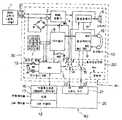
이를 제1도 내지 제5도의 도면에 의하여 순차적으로 설명한다. 제1도는 본 발명의 네트워크용 전화기가 퍼스널 컴퓨터에 연결된 상태를 나타내는 실시도로서, 공중 또는 사설교환기(1)에서 전화선을 통하여 네트워크용전화기(30)에 연결되고, 이 네트워크용 전화기(30)를 통하여 컴퓨터 본체(40)에 연결된다.This will be described sequentially with the drawings of FIGS. 1 to 5. 1 is a diagram showing a state in which a network telephone of the present invention is connected to a personal computer. The telephone is connected to the
이 네트워크용 전화기(30)는 일반적인 전화기회로들을 가지고 있는 전화기부(10)와, 이 전화기부(10)이 회로 연결을 제어하는 제어부(20)로 구별된다.This
상기 전화기부(10)는 전화선(2)과 전화기의 연결여부를 결정하는 훅크스위치(HS1),(HS2)와 포토카플러(3)의 일측을 통하여 연결되는 링검출기(4)와, 링검출기(4)의 출력이 인가되는 스피커(6)와, 키보드(7)의 신호가 인가되는 다이얼러(8)와, 송수화기(19)에 입출력되는 음성신호를 처리하는 음성처리기(9)와, 상기 음성처리기(9)에 연결되어 외부로 음성신호 출력시 스피커(6)로 증폭출력하는 음성증폭기(11)로 구성된다.The telephone unit 10 has a
여기서 훅크스위치(MS2)는 상기 다이얼러(8)와 MPU(5)에 송수화기의 위치상태를 입력하기 위한 스위치이며, 훅크스위치(HS1)는 다이얼러(9)의 신호입력(HS)에 따라 국선을 연결 또는 해제하는 연동 스위치이므로 훅크스위치(HS2)가 오픈상태인 경우에도 MPU(5)의 출력에 의하여 국선의 연결, 해제가 가능하도록 구성되어 있다.Here, the hook switch MS2 is a switch for inputting the position state of the handset to the
상기 전화기부(10)를 제어하는 제어부(20)는 모우드전환스위치(12) 및 모우드표시용 발광다이오드(13)에 연결되고, 포토카플러(3), 키보드(7), 다이얼러(8) 및 음성증폭기(11)에 연결된 MPU(5)와, 상기 MPU(5)에 의하여 제어되고, 전화기부(10)의 음성처리기(9)의 출력에 연결 또는 음서증폭부(11)의 출력부에 연결을 선택하는 전환스위치(14)와, 상기 MPU(5)에 의하여 제어되고, 전화기부(10)의 음성처리기(9)에 연결단자(RXI),(TXI)를 선택하는 전환스위치(15)로 구성되어 있다.The
상기 컴퓨터 본체(40)는 내부에 직렬통신포트(16), 모뎀(17), LAN어댑터(18), 사운드카드(21)를 구비하여 내부 컴퓨터 기판(25)에 연결되어 있다.The computer
그리고 상기 제어부(20)의 MPU(5)는 직렬통신포트(16)를 통하여 컴퓨터 기판(25)에, 제어부(20)의 전환스위치(14),(15)는 각각 컴퓨터 본체(40) 내부 사운드 카드(21)의 입력단자(22)과 출력단자(23)를 통하여 연결되어 있다.The
제2도는 본 발명의 네트워크용 전화기에서 음성처리시 신호처리경로를 나타낸 회로도로서, 제1도의 음성처리기(9)의 내부를 구체적으로 나타내고 있으나, 이는 일반적인 전화기 회로의 구성과 일치한다.FIG. 2 is a circuit diagram showing a signal processing path during voice processing in the network telephone of the present invention. Although the inside of the
이 회로에서는 전환스위치(14), (15)가 네트워크를 통한 인터넷단자(I)에 연결된 상태를 나타내고 있는 것으로, 컴퓨터의 오디오 출력은 사운드카드의 출력단자(23)로 출력되는 오디오신호는 전화기 음성처리기(9)의 수신증폭부(31)를 통하여 수화기 또는 음성증폭기(11)를 통하여 전화기내장 스피커(6)로 출력되며, 송화기로 입력된 음성신호는 마이크 증폭부(32)를 통하고 자동이득조절부(AGC)(33)를 거처 컴퓨터의 사운드카드(21)의 오디오 입력단자(22)로 연결되어 송수화기를 통하여 전화기 고유의 사용 주파수대역으로 여과된 상태로 통화를 하게된다.In this circuit, the switching switches 14 and 15 are connected to the Internet terminal I via a network. The audio output of the computer is output to the
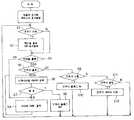
제3도는 본 발명의 네트워크용 전화기의 주 플로우챠트로서, 제어부(20)의 MPU(5)에 대한 동작을 나타내고 있다. MPU는 초기 스타트 스텝수행후 입출력초기화 및 레지스터의 초기 값을 설정하게 된다. 그리고 스텝(S1)에서 전화기 모우드에 변화가 있는지 여부를 살피게 된다. 즉 통화상태에서 대기상태로 전환되었는지 대기상태에서 통화상태로 되었는지 등, 현재의 모우드에서 다른 모우드의 전환이 있는지 여부를 살피게된다. 모우드변환이 있는 경우 예를들면, 제1도에서 모우드전환키(12)를 눌렀을 경우와 같이 모우드 변환이 있는 경우에는 스텝(S2)으로 넘어가 확인임을 출력하고, 모우드표시용 발광다이오드(13)를 점등시킨후 스텝(S3)으로 넘어가게 된다. 모우드 변화가 없는 경우에는 바로 다이얼 플래그확인(S3)으로 넘어가 다이얼 플래그가 있는지 살피게 되고, 다이얼 플래그가 있는 경우에는 스텝(S4)을 수행하여 다이얼톤을 출력하게 된다.3 shows the operation of the
만약 스텝(S3)에서 다이얼 플래그가 없는 경우에는 스텝(S5)으로 넘어가 단축키 플래그가 있는지 검사하여 단축키 작동상태인 경우에는 스텝(S6)에서 메모리에 저장되어 있는 단축다이얼 데이타를 순차적으로 검색후 스텝(S7)을 통하여 스텝(S4)으로 진행되어 다이얼톤 신호를 출력하게 된다. 그리고 스텝(S7)에서 종료가 판단되면 스텝(S8)으로 진행후 단축키 플래그를 오프하게 된다.If there is no dial flag at step S3, the process proceeds to step S5 and checks if there is a shortcut flag. If the shortcut key is in operation, step S6 searches sequentially the speed dial data stored in the memory and then steps ( The process proceeds to step S4 through S7) to output the dial tone signal. If it is determined in step S7 that the end is completed, the flow proceeds to step S8 and the shortcut key flag is turned off.
여기서 다이얼 플래그를 오프하는 것은 단축다이얼 기능의 완전한 수행을 위한 것이다.Turning off the dial flag here is for complete performance of the speed dial function.
여기서 순차적으로 스텝(S6, S7, S4)을 선택후 다시 스텝(S3), (S5)를 통하여 순환되게 하는 이유는 전화번호의 자리수가 2이상이 되기 때문에 순차적으로 다이얼링할 수 있게 한 것이다.The reason why the steps S6, S7 and S4 are sequentially selected and then circulated again through the steps S3 and S5 is that the number of digits of the telephone number becomes 2 or more, so that dialing can be performed sequentially.
스텝(S3), (S5)의 상태는 대체적으로 컴퓨터에서 다이얼코드 전송으로 직렬통신 인터럽트에서 다이얼 플래그 신호가 설정되거나 키보드(7)로 단축키 누름에 의한 단축키 플래그신호가 인가된 경우나, 일반적으로 전화를 걸거나 할때에는 제1도에서 전화기부(10)의 키패드(7)를 통하여 다이얼(8)를 구동시키게 되는 것으로 이 플로우 챠트와는 관계가 없다. 이는 상술한 바와같이 MPU(5)가 수행하는 처리를 나타내고 있으나, 일반 전화기 동작은 바로 전화기부(10) 자체에서 수행되기 때문이다.The state of steps S3 and S5 is generally when the dial flag signal is set in the serial communication interrupt by the dial code transmission from the computer or when the shortcut flag signal is applied by pressing the shortcut key on the
또한 본 발명에서는 일반적인 전화기를 사용하고 있기 때문에 자체에 단축키의 기능이 없으나, 이 기능은 별도로 MPU(5)에서 수행하고 있다. 따라서 스텝(S9)에서 단축키가 눌러졌음을 확인하면 스텝(S10)으로 진행되어 단축키 플래그를 온한후 다시 스텝(S1-S3)를 수행하고, 스텝(S5)에서 상술한 바와같이 단축다이얼 데이타 검색후 순차적으로 다이얼을 하게 된다. 또한 스텝(S9)에서 단축키의 누름이 없는 경우에는 단축키를 설정하는 스텝(S11)으로 진행되어 단축키 데이타 저장을 스텝(S12)에서 하게 되고, 다음에 이 단축키를 사용하는 경우 상술한 플로우대로 동작을 진행하게 된다.In addition, in the present invention, since a general telephone is used, there is no function of a shortcut key on its own, but this function is separately performed by the
이 제3도의 플로우 챠트에 의하면 일반전화기의 기능을 그대로 수행하면서 MPU에 의하여 단축키 설정 및 단축키에 의한 다이얼링의 기능이 부가 되고, 모우드 변화에 따라 모우드의 표시 및 컴퓨터에 의한 다이얼 플래그 및 단축키 플래그에 의한 다이얼링 기능을 모두 수행하게 된다.According to the flow chart of FIG. 3, the MPU adds a function of setting a shortcut key and dialing by a shortcut key while performing the functions of a general telephone. The display of the mode according to the mode change and the dial flag and the shortcut key by the computer are performed. All dialing functions will be performed.
이와같이 일반전화기나 컴퓨터에 의한 제어모우드등을 수행시 MPU(5)는 현재 전화기의 상태를 컴퓨터에 알려주고, 또한 컴퓨터에 의한 제어명령을 MPU(5)에서 받아 전화기를 제어할 필요가 있다.In this manner, when performing a control mode by a general telephone or a computer, the
따라서 MPU(5)는 제1도의 직렬통신 포트(16)를 통하여 제4도의 플로우를 수행하면서 CPU를 포함하고 있는 컴퓨터기판(25)의 제어명령을 받고 있다.Accordingly, the
즉, 제4도는 본 발명의 네트워크용 전화기에서 직렬통신 인터럽트에 대한 플로우챠트로서, 직렬통신 인터럽트가 생긴 경우 즉, 제1도의 직렬통신 포트(16)를 통하여 컴퓨터 기판(25)의 제어신호가 인가 되는 경우 스텝(S15)에서 그 직렬데이타를 수신하게 된다. 이 데이타를 판단하는 스텝(S6-S19)에서 이에 대한 적절한 동작을 MPU(5)에서 수행하게 되는 것으로 조회코드의 문의시에는 스텝(S20)에서 상태코드를 송신하여 현재 전화기의 상태를 알려주게 되고, 스텝(S17)에 해당하는 제어명령인 경우에는 이에 따라 스텝(S21)에서 모우드변환, 음성경로 변환, 국선선택/해제 등의 명령을 수행하게 된다. 그리고, 직렬데이타 신호가 다이얼 코드 스텝(S18)에서 다이얼코드로 판정되면, 스텝(S22)에서 다이얼 플래그온을 시키게 되고, 단축키 설정 스텝(S19)에서는 스텝(S23)으로 넘어가 단축다이얼에 대한 데이타를 저장하게 된다.That is, FIG. 4 is a flowchart of serial communication interrupt in the network telephone of the present invention. When a serial communication interrupt occurs, that is, a control signal of the
즉, 조회코드 판별스텝(S16)에서는 컴퓨터가 전화를 사용하고자 할때에 현재 전화기의 상태를 MPU를 통하여 알수 있게 되고, 제어명령 스텝(S17)에서는 인가 되는 제어명령에 따라 MPU가 전화기부(10)를 제어하여 원하는 모우드 즉, 인터넷 통신모우드, 자동수신모우드, 일반 전화기모우드등으로 전환시키게 된다.That is, in the inquiry code determination step (S16), when the computer wants to use the telephone, the state of the current telephone can be known through the MPU, and in the control instruction step (S17), the MPU transmits the telephone unit 10 according to the control command applied. ) To switch to the desired mode, that is, the Internet communication mode, the automatic receiving mode, and the general telephone mode.
이와함께 전화기의 상태가변화되면, MPU(5)에서 그 모우드가 변화된 것을 컴퓨터에 알려주어 다음동작을 수행할 수 있게 한 것으로 이때에는 전화기의 상태변화 인터럽트의 플로우에 따라 구동하게 된다.At the same time, when the state of the phone changes, the
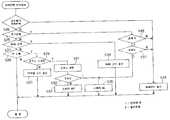
제5도는 본 발명의 네트워크용 전화기에서 전화기의 상태변화에 따른 인터럽트에 대한 플로우 챠트로서, 전화기의 상태변화에 따른 모우드의 변화시 수행되는 인터럽트이다.5 is a flowchart of the interruption according to the state change of the phone in the network phone of the present invention, and is an interrupt performed when the mode is changed according to the state change of the phone.
즉, MPU는 스텝(S25-S28)을 수행하여 현재의 전화기의 상태를 판단한다. 즉, 송수화기 위치상태, 훅크스위치 동작상태, 링신호상태, 키누름상태등을 파악한다. 송수화기의 위치변화가 없는 경우에는 스텝(S25)에서 스텝(S26)으로 진행되고, 송수화기의 위치변화가 있는 상태에서는 스텝(S38)으로 진행되어 퍼스널 컴퓨터에 그 상태코드를 보내주게 된다.That is, the MPU performs steps S25-S28 to determine the state of the current telephone. That is, the handset position status, hook switch operation status, ring signal status, key press status, and the like are identified. If there is no change in the position of the handset, the process proceeds from step S25 to step S26, and if the position of the handset is changed, the process proceeds to step S38 and the status code is sent to the personal computer.
스텝(S26)에서는 다이얼러(8)의 논리적 훅크상태 변화를 파악한다. 송수화기를 들고 있는 상태에서는 훅크스위치(HS2)에 의하여 훅크스위치(HS1)가 작동하는 오프훅크 상태가 되며, 송수화기가 놓여져 있어도 일반전화기에 온훅크 다이얼 스위치를 작동하거나 MPU(5)에서 훅크스위치(HS2)의 제어출력으로도 오프상태도 될 수 있으므로 훅크상태 변화시에는 스텝(S36)에서 온훅크여부를 판단하여 온푹크여부를 판단하여 오프훅크상태인 경우에는 스텝(S38)로 진행되고, 온훅크상태인 경우에는 스텝(S37)에서 네트워크 폰(인터넷폰)인가 일반전화 모우드인가를 판단하고, 네트워크폰인 경우에는 스피커온(스텝 S6)을 하여 음향출력을 사용자가 알수있게 한다.In step S26, the logical hook state change of the
링신호가 인가되는 경우에는 스텝(S27)에서 판단하여 스텝(S34)을 통하여 링코드를 송출하게 된다.When a ring signal is applied, the ring code is transmitted through step S34 by judging at step S27.
스텝(S28)에서 키누름이 있는 경우에는 스텝(S29)을 통하여 모우드 전환스위치(12)인가를 판단하고 모우드 스위치(12)가 아닌 경우에는 스텝(S30)을 통하여 키보드(7)에 해당하는 다이얼코드를 송신하고, 모우드 전환스위치(12)가 눌러졌을 경우 스텝(S31)을 진행하여 모우드 전환을 하게 된다. 그후 그 모우드가 네트워크 모우드인지 보통 전화모우드인지를 스텝(S34)에서 판별하여 보통 전화모우드시에는 스텝(S38)을 진행하여 전화기 내부 스피커를 오프상태로 두며, 네트워크 모우드인 경우에는 스텝(S35)으로 진행되어 전화기 내부 스피커를 온상태를 유지하여 네트워크로 부터의 호출을 소리로써 확인할수 있게 되고, 전화기의 송수화기를 들면 일반전화기처럼 통화할수 있게 된다.If there is a key press in step S28, it is determined whether the
물론 송수화기를 들어 통화하는 경우에는 제5도에서 상태변화 모우드를 확인하여 즉, 스텝(S25) 및 스텝(S38)을 거쳐 통화중인 상태코드를 컴퓨터기판(25)에 인가하여 호출응답을 확인할수 있게한다.Of course, when making a call using the handset, the state change mode is checked in FIG. 5, that is, the call status is applied to the
이와같은 본 발명을 동작을 각각의 전화기 모우드 별도 구별하여 설명하면 다음과 같다.When the present invention is described by distinguishing each phone mode separately operation as follows.
(1) 네트워크를 통하여 인터넷폰 모우드로 사용시,(1) When used as an internet phone mode through a network,
일반적으로 네트워크 연결시에는 퍼스널 컴퓨터의 모뎀이나, LAN어댑터를 통하여 원하는 IP주소에 연결을 한후 인터넷폰 프로그램을 통하여 통하를 하게 된다.In general, when connecting to a network through a personal computer modem or LAN adapter to the desired IP address through the Internet phone program through the program.
이때, 네트워크에 연결후 직렬통신포트(16)를 통하여 인가되는 상태신호를 제4도 플로우의 스텝(S16)을 통하여 전화기의 상태를 감지한다. 통화중인 아닌 상태에서 네트워크와 연결시 스텝(S17)을 통하여 제어명령을 파악하여 스텝(S21)으로 진행되어 모우드 변환, 음성경로를 변환하고, 국선 선택/해제의 동작을 MPU에서 훅크스위치 및 전환스위치(14),(15)를 제어하여 전화기 회로가 제2도와 같은 연결상태가 유지되게 한다.At this time, the state signal applied through the
이와같은 모우드의 변환에 따라 전화기의 상태변화 인터럽트를 제5도와 같이 수해하는 것으로 네트워크에 연결시 송수화기가 놓여 있으므로 스텝(S26), 스텝(S36), 스텝(S37)의 순으로 진행되어 스텝(S35)을 통하여 전화기 내부의 스피커를 온시키게 된다.According to this mode conversion, the state change interrupt of the telephone is interrupted as shown in FIG. 5, and the handset is placed when connected to the network, so step S26, step S36, and step S37 are performed in step S35. Turn on the speaker inside the phone.
따라서 스피커(6)를 통하여 상태가 연결된 의사 호출음이 들여오면,전화기의 송수화기를 들고 통화를 하게 되며, 이때에는 스텝(S25), 스텝(S38)순으로 진행하여 현재 동화중임을 MPU에서 컴퓨터에 알려주게 된다.Therefore, when a pseudo call tone is connected through the
즉, 전화기이 내부회로가 제1도와 같이 연결된 상태에서는 송화기의 음성출력은 음성처리가(9)를 통하여 사운드장치의 입력단자(22)로 입력된후 모뎀(17) 또는 LAN어댑터(18)을 통하여 네트워크로 전송되고, 네트워크에 인가되는 음성신호는 모뎀(17) 또는 LAN어댑터를 통하여 사운드카드 출력단자(23)를 통하여 음성처리기(9)를 거쳐서 수화기로 인가되어 통화를 하게 된다.That is, when the telephone is connected to the internal circuit as shown in FIG. 1, the voice output of the talker is input to the
결국 컴퓨터의 오디오 출력신호는 전화기 음성처리기(9)의 수신증폭부(31)를 통하여 수화기 또는 전화기내장 스피커(6)로 출력되며, 송화기로 입력된 음성신호는 마이크 증폭부(32)를 통하고 자동이득조절부(AGC)(33)를 거쳐 컴퓨터의 오디오 입력단자로 연결되어 송수화기를 통하여 전화기 고유의 사용주파수대역으로 여과된 상태로 통화가 된다.As a result, the audio output signal of the computer is output to the handset or the built-in
그리고 네트워크를 통한 인터넷폰 사용시에는 전화선(2)과의 연결이 해제되고 음성 증폭기(11)가 작동상태로 되므로 컴퓨터로부터의 의사호출음(RING)이 자연스럽게 스피커로 출력되고 송수화기를 들면, 상태 신호에 의하여 인터넷폰 소프트웨어에서 필요한 전화받기 버튼작동을 종래의 마우스대신 자동작동하게 하므로써 일반전화기 처럼 자연스러운 사용이 가능하게 된다. 이상태에서도 전화기의 다이얼 작동시 그 내용이 컴퓨터에 전송되므로 다이얼 번호를 IP주소로 변환하는 소프트웨어와 결합하면 인터넷주소(IP)대신 보통전화번호로 인터넷전화를 호출할 수 있게 되며, 송수화기를 놓으면 전화 끊기가 자동으로 작동하게 된다.When using the Internet phone through the network, the connection with the
(2) 자동응답모우드시,(2) Auto answer mode
자동응답 모우드로 설정시는 제1도의 음성경로 전환스위치(14),(15)가 단자(a)에 연결된 상태로 설정된다.When the auto answer mode is set, the voice path change switches 14 and 15 of FIG. 1 are connected to the terminal a.
그리고, 수신대기중 전화국선을 통하여 전화기 걸려오면 제1도의 링검출기(4)를 통하여 스피커(6)로 호출음이 발생하는 동시에 링검출기(4) 앞단의 포토카플러(3)를 통하여 호출신호가 MPU(5)에 전달되고, MPU는 컴퓨터로 호출상태 신호를 전송한다. 즉, 제5도에서 스텝(S34)에서 링크도를 컴퓨터에 보내면, CPU가 포함된 컴퓨터기판(25)는 이를 인식하여 제어신호를 보내 전화기를 전화받기(오프훅크)상태로 전환하고(제4도에서 스텝 S17을 통하여 스텝S21를 수행), 컴퓨터에 미리 녹음된 음성안내신호를 오디오 출력단자를 통하여 전화기 음성처리의 AGC부(33)를 거처 국선을 통해 상대에게 전달한 후 국선을 통해 들어오는 상대방의 음성을 측음억압하여 음성처리기(9)의 AGC와 음성증폭기(11)를 거쳐 컴퓨터의 오디오 입력단자로 전달하여 컴퓨터에서는 이 신호를 압축하여 화일로 저장하여 향후에 재생할 수 있도록 한다. 종료시 호출대기(온훅크로 국선선택을 해제한 상태로 제4도에서 스텝 S17으로 동작) 상태로 전환시키며 필요시 컴퓨터에 미리 지정된 무선호출기의 번호로 자동다이얼링 할 수 있다.When a telephone is received through the telephone line during reception, a ringing tone is generated to the
(3) 개인교환기로서 사용예(3) Example of use as a personal exchange
LAN어댑터(18)에 연결된 컴퓨터 기판(25)과 결합하여 컴퓨터가 네트워크를 통한 인터넷폰 수신대기상태로 있는 경우에는 외부에서 인터넷접속으로 LAN어댑터(18)을 통하여 해당 컴퓨터를 호출하고 필요한 전화번호를 전송하면 컴퓨터는 부착된 전화기를 자동응답단자(A)에 연결되게 설정하고 오프훅크로 국선을 선택하여 다이얼링을 하고, 연결이 이루어지면 인터넷을 통해온 음성신호가 자동응답모우드의 음성신호경로를 통하여 상대방과 통화할 수 있다. 즉 인터넷을 통한 개인교환기(Personal Telephont gateway)역활을 수행하므로써 시외 또는 국외 지역에 관계없이 자신의 전화기로 시내(지역)통화(Local Call)를 이용할 수 있다.When the computer is connected to the
(4) 일반전화기로서 사용시(4) When using as a general telephone
수동모우드 전환버튼(12)로 일반전화와 인터넷전화기능을 전환하고 그 상태를 모우드표시용 발광다이오드(13)로 표시한다.The manual
또 MPU(5)의 기억수단(램)을 이용하여 단축다이얼 데이터를 전화기 키보드 또는 컴퓨터로부터 저장하며 단축다이얼 기능을 수행할 수 있다.In addition, by using the storage means (RAM) of the
물론 상기(3) 및 (4)의 모우드의 경우에도 제4도의 직렬통신 인터럽트를 수행하여 컴퓨터로 부터 MPU를 제어하고, 전화기의 모우드상태의 변화에 따라 제5도의 상태변화 인터럽트를 수행하여 MPU에서 컴퓨터에 현재의 전화기의 상태를 알려주어 모우드 전환을 정확하게 할수 있다.Of course, in case of the modes (3) and (4), the MPU is controlled from the computer by performing the serial communication interrupt of FIG. 4, and the state change interrupt of FIG. 5 is performed by the MPU according to the change of the state of the telephone. You can tell the computer the current state of the phone so that the mode switch is accurate.
이상에서와 같이 본 발명은 공중교환기나 구내교환기용 통상의 전화기회로에 컴퓨터와 제어신호를 주고 받고 장치를 설치하여 전화기의 음성처리기에 적절한 음성신호경로를 조절하여 컴퓨터의 음향장치에 연결하므로써 통화명료도가 높은 사용주파수대역(In Band, 300∼3400Hz)이외의 주파수를 감쇄하여 송수화기를 통하여 통화할 수 있으며, 전화기의 작동상태(인터넷폰상태, 자동응답상태, 국선연결상태, 핸드세트상태)와 키 누름상태를 컴퓨터에 전송하고 컴퓨터로부터 상태전환신호, 다이얼키조작신호를 수신하여 수행하므로써, 컴퓨터의 소프트웨어와 결합하여 다양한 부가기능을 수행하므로써, 기존 인터넷폰의 통화품질과 사용상의 편리성을 개선하여 실용성을 보장할 수 있으며, 기존 컴퓨터의 자원과 기능을 최대한 활용할 수가 이다.As described above, the present invention transmits and receives a control signal with a computer in a common telephone circuit for an air exchange or an internal exchange, and installs a device to adjust the appropriate voice signal path to the voice processor of the telephone to connect to the sound device of the computer. You can make a call through the handset by attenuating frequencies other than the high frequency band (In Band, 300 to 3400 Hz), and operate the phone (Internet phone status, auto answer state, trunk line connection, handset status) and keys. By transmitting the push status to the computer and receiving the status change signal and dial key operation signal from the computer, it performs various additional functions in combination with the software of the computer, thereby improving the call quality and convenience of use of the existing Internet phone. Practicality can be guaranteed and you can make the most of the resources and features of your existing computer.
또한 앞으로 대부분의 기업 및 기관이 LAN환경에서 1인 1컴퓨터의 사용이 보편화되는 경우에는 일반전화, 인터넷 전화기능외에 부가기능으로 자동응답기능, 음성사서함기능, 음성안내기능, 지정번호호출기능, 전자우편 도착알림기능 등을 간단한 소프트웨어와 결합하여 구현 할수 있는 효과가 있어 장래에 표준사무기기로서의 역할을 수행할 수도 있다.In addition, if most companies and organizations are using a one-person computer in a LAN environment in the future, in addition to the general telephone and Internet telephone functions, additional functions such as an automatic answering function, a voice mail function, a voice guidance function, a designated number call function, and an electronic The mail arrival notification function can be combined with simple software, and may serve as a standard office device in the future.
Claims (5)
Translated fromKoreanPriority Applications (1)
| Application Number | Priority Date | Filing Date | Title |
|---|---|---|---|
| KR1019970006603AKR100221772B1 (en) | 1997-02-28 | 1997-02-28 | Network-telephone |
Applications Claiming Priority (1)
| Application Number | Priority Date | Filing Date | Title |
|---|---|---|---|
| KR1019970006603AKR100221772B1 (en) | 1997-02-28 | 1997-02-28 | Network-telephone |
Publications (2)
| Publication Number | Publication Date |
|---|---|
| KR19980069507A KR19980069507A (en) | 1998-10-26 |
| KR100221772B1true KR100221772B1 (en) | 1999-09-15 |
Family
ID=19498383
Family Applications (1)
| Application Number | Title | Priority Date | Filing Date |
|---|---|---|---|
| KR1019970006603AExpired - Fee RelatedKR100221772B1 (en) | 1997-02-28 | 1997-02-28 | Network-telephone |
Country Status (1)
| Country | Link |
|---|---|
| KR (1) | KR100221772B1 (en) |
Cited By (2)
| Publication number | Priority date | Publication date | Assignee | Title |
|---|---|---|---|---|
| KR20020038859A (en)* | 2000-11-18 | 2002-05-24 | 정택구 | Telephone adaptor apparatus |
| KR20200023097A (en) | 2018-08-24 | 2020-03-04 | 임다영 | Apparatus for printing identification mark on electric wire |
Families Citing this family (5)
| Publication number | Priority date | Publication date | Assignee | Title |
|---|---|---|---|---|
| KR100576022B1 (en)* | 1998-12-24 | 2006-08-18 | 삼성전자주식회사 | Mobile terminal device with mobility in private exchange |
| KR100339872B1 (en)* | 1999-11-27 | 2002-06-10 | 최성수 | A method and automatic translation apparatus between public telephone call and internet phone call by using hook flash or feature button |
| KR100807055B1 (en)* | 1999-12-20 | 2008-02-25 | 주식회사 케이티 | How to automatically connect to the Internet using dial-up networking |
| KR100405591B1 (en)* | 2000-03-24 | 2003-11-14 | 김성철 | Internet phone exchanger with gateway feature |
| KR100381314B1 (en)* | 2001-04-30 | 2003-04-26 | 다산 일렉트론 주식회사 | Headset amplifier for public phone and internet phone |
- 1997
- 1997-02-28KRKR1019970006603Apatent/KR100221772B1/ennot_activeExpired - Fee Related
Cited By (2)
| Publication number | Priority date | Publication date | Assignee | Title |
|---|---|---|---|---|
| KR20020038859A (en)* | 2000-11-18 | 2002-05-24 | 정택구 | Telephone adaptor apparatus |
| KR20200023097A (en) | 2018-08-24 | 2020-03-04 | 임다영 | Apparatus for printing identification mark on electric wire |
Also Published As
| Publication number | Publication date |
|---|---|
| KR19980069507A (en) | 1998-10-26 |
Similar Documents
| Publication | Publication Date | Title |
|---|---|---|
| KR100221772B1 (en) | Network-telephone | |
| US20030032393A1 (en) | Personal computer phone patch | |
| KR200189400Y1 (en) | Telephone for use with telephone line and internet line | |
| KR100463504B1 (en) | Utility phone with Internet phone function | |
| KR100405591B1 (en) | Internet phone exchanger with gateway feature | |
| JP2809651B2 (en) | Communication device | |
| EP1392040A2 (en) | Communication apparatus with one-way speakerphone function | |
| JPH07131550A (en) | Electronic notebook and telephone | |
| KR0125317Y1 (en) | Telephone | |
| JPH055429B2 (en) | ||
| JP3704456B2 (en) | Telephone | |
| JP5010779B2 (en) | Cordless telephone and incoming call processing method | |
| KR200168870Y1 (en) | Versatility keyboard having audio listening and telephone function | |
| KR20000030396A (en) | Internet phone exchanger | |
| KR200277275Y1 (en) | Telephone having auto calling router | |
| JPS61281656A (en) | Telephone set system | |
| JP2586722Y2 (en) | Telephone | |
| KR100681337B1 (en) | Computer Controlled Multifunction Phone | |
| KR19980035372A (en) | Communication terminal with automatic continuous redial | |
| JP3088379B2 (en) | Communication terminal device with speakerphone call function | |
| KR100838960B1 (en) | Automatic incoming method and device of mobile communication terminal | |
| JP2590458Y2 (en) | Cordless telephone | |
| JPH11266291A (en) | Communication device and storage medium | |
| KR19980052725A (en) | Emergency dialing method of telephone handset | |
| KR20010091290A (en) | Exterior switch for connecting a normal telephone and an voice over internet protocol phone, and telephone set using the same |
Legal Events
| Date | Code | Title | Description |
|---|---|---|---|
| A201 | Request for examination | ||
| PA0109 | Patent application | St.27 status event code:A-0-1-A10-A12-nap-PA0109 | |
| PA0201 | Request for examination | St.27 status event code:A-1-2-D10-D11-exm-PA0201 | |
| R17-X000 | Change to representative recorded | St.27 status event code:A-3-3-R10-R17-oth-X000 | |
| PG1501 | Laying open of application | St.27 status event code:A-1-1-Q10-Q12-nap-PG1501 | |
| E701 | Decision to grant or registration of patent right | ||
| PE0701 | Decision of registration | St.27 status event code:A-1-2-D10-D22-exm-PE0701 | |
| GRNT | Written decision to grant | ||
| PR0701 | Registration of establishment | St.27 status event code:A-2-4-F10-F11-exm-PR0701 | |
| PR1002 | Payment of registration fee | St.27 status event code:A-2-2-U10-U11-oth-PR1002 Fee payment year number:1 | |
| PG1601 | Publication of registration | St.27 status event code:A-4-4-Q10-Q13-nap-PG1601 | |
| G170 | Re-publication after modification of scope of protection [patent] | ||
| PG1701 | Publication of correction | St.27 status event code:A-5-5-P10-P19-oth-PG1701 Patent document republication publication date:19991201 Republication note text:Request for Correction Notice Gazette number:1002217720000 Gazette reference publication date:19990915 | |
| S14-X000 | Exclusive voluntary license recorded | St.27 status event code:A-4-4-S10-S14-lic-X000 | |
| PR1001 | Payment of annual fee | St.27 status event code:A-4-4-U10-U11-oth-PR1001 Fee payment year number:4 | |
| PR1001 | Payment of annual fee | St.27 status event code:A-4-4-U10-U11-oth-PR1001 Fee payment year number:5 | |
| PR1001 | Payment of annual fee | St.27 status event code:A-4-4-U10-U11-oth-PR1001 Fee payment year number:6 | |
| PR1001 | Payment of annual fee | St.27 status event code:A-4-4-U10-U11-oth-PR1001 Fee payment year number:7 | |
| PR1001 | Payment of annual fee | St.27 status event code:A-4-4-U10-U11-oth-PR1001 Fee payment year number:8 | |
| PR1001 | Payment of annual fee | St.27 status event code:A-4-4-U10-U11-oth-PR1001 Fee payment year number:9 | |
| PR1001 | Payment of annual fee | St.27 status event code:A-4-4-U10-U11-oth-PR1001 Fee payment year number:10 | |
| PR1001 | Payment of annual fee | St.27 status event code:A-4-4-U10-U11-oth-PR1001 Fee payment year number:11 | |
| FPAY | Annual fee payment | Payment date:20100610 Year of fee payment:12 | |
| PR1001 | Payment of annual fee | St.27 status event code:A-4-4-U10-U11-oth-PR1001 Fee payment year number:12 | |
| LAPS | Lapse due to unpaid annual fee | ||
| PC1903 | Unpaid annual fee | St.27 status event code:A-4-4-U10-U13-oth-PC1903 Not in force date:20110630 Payment event data comment text:Termination Category : DEFAULT_OF_REGISTRATION_FEE | |
| PC1903 | Unpaid annual fee | St.27 status event code:N-4-6-H10-H13-oth-PC1903 Ip right cessation event data comment text:Termination Category : DEFAULT_OF_REGISTRATION_FEE Not in force date:20110630 | |
| P22-X000 | Classification modified | St.27 status event code:A-4-4-P10-P22-nap-X000 |